EP4456094A1 - Solenoidanordnung und verfahren zu deren herstellung - Google Patents
Solenoidanordnung und verfahren zu deren herstellung Download PDFInfo
- Publication number
- EP4456094A1 EP4456094A1 EP23169948.9A EP23169948A EP4456094A1 EP 4456094 A1 EP4456094 A1 EP 4456094A1 EP 23169948 A EP23169948 A EP 23169948A EP 4456094 A1 EP4456094 A1 EP 4456094A1
- Authority
- EP
- European Patent Office
- Prior art keywords
- connector assembly
- valve unit
- assembly
- solenoid
- valve
- Prior art date
- Legal status (The legal status is an assumption and is not a legal conclusion. Google has not performed a legal analysis and makes no representation as to the accuracy of the status listed.)
- Pending
Links
Images


Classifications
-
- H—ELECTRICITY
- H01—ELECTRIC ELEMENTS
- H01R—ELECTRICALLY-CONDUCTIVE CONNECTIONS; STRUCTURAL ASSOCIATIONS OF A PLURALITY OF MUTUALLY-INSULATED ELECTRICAL CONNECTING ELEMENTS; COUPLING DEVICES; CURRENT COLLECTORS
- H01R13/00—Details of coupling devices of the kinds covered by groups H01R12/70 or H01R24/00 - H01R33/00
- H01R13/73—Means for mounting coupling parts to apparatus or structures, e.g. to a wall
-
- F—MECHANICAL ENGINEERING; LIGHTING; HEATING; WEAPONS; BLASTING
- F16—ENGINEERING ELEMENTS AND UNITS; GENERAL MEASURES FOR PRODUCING AND MAINTAINING EFFECTIVE FUNCTIONING OF MACHINES OR INSTALLATIONS; THERMAL INSULATION IN GENERAL
- F16K—VALVES; TAPS; COCKS; ACTUATING-FLOATS; DEVICES FOR VENTING OR AERATING
- F16K31/00—Actuating devices; Operating means; Releasing devices
- F16K31/02—Actuating devices; Operating means; Releasing devices electric; magnetic
- F16K31/06—Actuating devices; Operating means; Releasing devices electric; magnetic using a magnet, e.g. diaphragm valves, cutting off by means of a liquid
- F16K31/0675—Electromagnet aspects, e.g. electric supply therefor
-
- H—ELECTRICITY
- H01—ELECTRIC ELEMENTS
- H01F—MAGNETS; INDUCTANCES; TRANSFORMERS; SELECTION OF MATERIALS FOR THEIR MAGNETIC PROPERTIES
- H01F5/00—Coils
- H01F5/04—Arrangements of electric connections to coils, e.g. leads
-
- H—ELECTRICITY
- H01—ELECTRIC ELEMENTS
- H01F—MAGNETS; INDUCTANCES; TRANSFORMERS; SELECTION OF MATERIALS FOR THEIR MAGNETIC PROPERTIES
- H01F7/00—Magnets
- H01F7/06—Electromagnets; Actuators including electromagnets
-
- H—ELECTRICITY
- H01—ELECTRIC ELEMENTS
- H01F—MAGNETS; INDUCTANCES; TRANSFORMERS; SELECTION OF MATERIALS FOR THEIR MAGNETIC PROPERTIES
- H01F7/00—Magnets
- H01F7/06—Electromagnets; Actuators including electromagnets
- H01F7/08—Electromagnets; Actuators including electromagnets with armatures
- H01F7/127—Assembling
-
- H—ELECTRICITY
- H01—ELECTRIC ELEMENTS
- H01F—MAGNETS; INDUCTANCES; TRANSFORMERS; SELECTION OF MATERIALS FOR THEIR MAGNETIC PROPERTIES
- H01F7/00—Magnets
- H01F7/06—Electromagnets; Actuators including electromagnets
- H01F7/08—Electromagnets; Actuators including electromagnets with armatures
- H01F7/128—Encapsulating, encasing or sealing
-
- H—ELECTRICITY
- H01—ELECTRIC ELEMENTS
- H01R—ELECTRICALLY-CONDUCTIVE CONNECTIONS; STRUCTURAL ASSOCIATIONS OF A PLURALITY OF MUTUALLY-INSULATED ELECTRICAL CONNECTING ELEMENTS; COUPLING DEVICES; CURRENT COLLECTORS
- H01R12/00—Structural associations of a plurality of mutually-insulated electrical connecting elements, specially adapted for printed circuits, e.g. printed circuit boards [PCB], flat or ribbon cables, or like generally planar structures, e.g. terminal strips, terminal blocks; Coupling devices specially adapted for printed circuits, flat or ribbon cables, or like generally planar structures; Terminals specially adapted for contact with, or insertion into, printed circuits, flat or ribbon cables, or like generally planar structures
- H01R12/70—Coupling devices
- H01R12/71—Coupling devices for rigid printing circuits or like structures
- H01R12/712—Coupling devices for rigid printing circuits or like structures co-operating with the surface of the printed circuit or with a coupling device exclusively provided on the surface of the printed circuit
-
- H—ELECTRICITY
- H01—ELECTRIC ELEMENTS
- H01R—ELECTRICALLY-CONDUCTIVE CONNECTIONS; STRUCTURAL ASSOCIATIONS OF A PLURALITY OF MUTUALLY-INSULATED ELECTRICAL CONNECTING ELEMENTS; COUPLING DEVICES; CURRENT COLLECTORS
- H01R13/00—Details of coupling devices of the kinds covered by groups H01R12/70 or H01R24/00 - H01R33/00
- H01R13/02—Contact members
- H01R13/22—Contacts for co-operating by abutting
- H01R13/24—Contacts for co-operating by abutting resilient; resiliently-mounted
- H01R13/2407—Contacts for co-operating by abutting resilient; resiliently-mounted characterized by the resilient means
-
- H—ELECTRICITY
- H01—ELECTRIC ELEMENTS
- H01R—ELECTRICALLY-CONDUCTIVE CONNECTIONS; STRUCTURAL ASSOCIATIONS OF A PLURALITY OF MUTUALLY-INSULATED ELECTRICAL CONNECTING ELEMENTS; COUPLING DEVICES; CURRENT COLLECTORS
- H01R13/00—Details of coupling devices of the kinds covered by groups H01R12/70 or H01R24/00 - H01R33/00
- H01R13/02—Contact members
- H01R13/22—Contacts for co-operating by abutting
- H01R13/24—Contacts for co-operating by abutting resilient; resiliently-mounted
- H01R13/2464—Contacts for co-operating by abutting resilient; resiliently-mounted characterized by the contact point
-
- H—ELECTRICITY
- H01—ELECTRIC ELEMENTS
- H01R—ELECTRICALLY-CONDUCTIVE CONNECTIONS; STRUCTURAL ASSOCIATIONS OF A PLURALITY OF MUTUALLY-INSULATED ELECTRICAL CONNECTING ELEMENTS; COUPLING DEVICES; CURRENT COLLECTORS
- H01R13/00—Details of coupling devices of the kinds covered by groups H01R12/70 or H01R24/00 - H01R33/00
- H01R13/46—Bases; Cases
- H01R13/502—Bases; Cases composed of different pieces
- H01R13/508—Bases; Cases composed of different pieces assembled by a separate clip or spring
-
- H—ELECTRICITY
- H01—ELECTRIC ELEMENTS
- H01R—ELECTRICALLY-CONDUCTIVE CONNECTIONS; STRUCTURAL ASSOCIATIONS OF A PLURALITY OF MUTUALLY-INSULATED ELECTRICAL CONNECTING ELEMENTS; COUPLING DEVICES; CURRENT COLLECTORS
- H01R43/00—Apparatus or processes specially adapted for manufacturing, assembling, maintaining, or repairing of line connectors or current collectors or for joining electric conductors
- H01R43/20—Apparatus or processes specially adapted for manufacturing, assembling, maintaining, or repairing of line connectors or current collectors or for joining electric conductors for assembling or disassembling contact members with insulating base, case or sleeve
- H01R43/205—Apparatus or processes specially adapted for manufacturing, assembling, maintaining, or repairing of line connectors or current collectors or for joining electric conductors for assembling or disassembling contact members with insulating base, case or sleeve with a panel or printed circuit board
-
- H—ELECTRICITY
- H01—ELECTRIC ELEMENTS
- H01F—MAGNETS; INDUCTANCES; TRANSFORMERS; SELECTION OF MATERIALS FOR THEIR MAGNETIC PROPERTIES
- H01F7/00—Magnets
- H01F7/06—Electromagnets; Actuators including electromagnets
- H01F2007/062—Details of terminals or connectors for electromagnets
Definitions
- the present invention relates to a method of manufacturing a solenoid assembly, a solenoid assembly and, in particular, to a new modular connector-solenoid assembly.
- solenoid assemblies offer only a single connector variant for a given solenoid assembly (e.g. for a particular customer). If a new connector variant is needed, it cannot be retrofitted directly. To introduce a new connector, it needs to be included on the same assembly line. This disturbs the solenoid assembly line, or different assembly lines are needed for the different connector variants.
- Figs. 5A and 5B illustrate a conventional solenoid assembly, wherein Fig. 5A shows an exploded view and Fig. 5B an overview.
- the solenoid assembly includes a valve assembly 10 couples to a plug connector 20.
- the valve assembly 10 includes a housing 80, a first solenoid valve 31 and a second solenoid valve 32, which are electrically contacted through a wiring 40 connected to the plug connector 20.
- the housing 80 accommodates the solenoid valves 31, 32, the wiring 40 and part of the plug connector 20.
- this conventional solenoid assembly the plug connector 20 is partly integrated into the housing 80 so that it cannot be replaced with another plug connector without disassembling the solenoid assembly.
- this conventional solenoid assembly comprises two housing portions which are connected to each other and thereby securing part of the plug connector 20 inside the housing 80.
- the plug connector 20 can only be replaced when the whole solenoid assembly is dismantled, i.e. the housing 80 has to be opened for this. Since the housing 80 is typically sealed, the replacements of the plug connector 20 will jeopardize the reliability of the whole solenoid assembly so that different plug connectors 20 have to be integrated during the assembly.
- the present invention relates a method for manufacturing a solenoid assembly.
- the method includes:
- the valve unit or the selected connector assembly includes a printed circuit board with electronic components configured to process the electrical signals received by the plug connection and to generate control signals for controlling the solenoid valve.
- valve unit can but does not need to include only a single valve but may include any number of electrically controlled valves.
- the step detachably mounting includes using at least one of the following connections:
- valve unit and the connector assembly can be pre-manufactured and mounted together by a press-fit or screw connection without any additional assembly process.
- the plurality of connector assemblies may include a first connector assembly with a first plug connection and a second connector assembly with a second plug connection, wherein the first plug connection and the second plug connection are different from each other.
- the (snap-fit or press-fit or screw) connection in the step of detachably mounting can be the same utilized for the first connector assembly and for the second connector assembly. Therefore, the first connector assembly and the second connector assembly are interchangeable and thus the selected connector assembly can be detached from the valve unit without opening the housing of the valve unit.
- the selected connector assembly can be replaced by another connector assembly without dismantling the solenoid assembly.
- the selected connector assembly may only be mounted to the valve unit through the detachable connection (e.g. the snap-fit connection and/or the screw connection and/or the press-fit connection).
- the step detachably mounting mounts the selected connector assembly as a side cover on the valve unit.
- the step of selecting the connector assembly selects a connector assembly having an oval plug connection or a circular plug connection or any other desired shape.
- the provided valve unit may include a plurality of valve pins being configured to provide an electric contact for the solenoid valve.
- the circuit board may comprise a contact structure with openings and may be secured in the selected connector assembly. Then, optionally, the step of detachably mounting includes introducing (simultaneously) the valve pins in the contact openings of the printed circuit board.
- the electric contact may also be established using spring contacts, plugs, clamps, terminals, contact pads, or any other suitable means.
- the provided valve unit may include the printed circuit board being electrically connected to the solenoid valve. Then, optionally, the step of detachably mounting the selected connector assembly includes electrically contacting the contacts of the plug connection with the printed circuit board in the valve unit. The electric contact may again be established using contact pins, spring contacts, plugs, clamps, terminals, contact pads, or any other suitable means.
- the provided the valve unit may include a cover that partially covers the printed circuit board secured in the valve unit (e.g. on one side of the housing).
- the cover includes an opening leaving part of the printed circuit board exposed.
- the step of detachably mounting may include mounting the selected connector assembly on the opening of the cover of the valve unit (to close the opening). This mounting onto the opening may again be performed simultaneously (at the same time) with the step of connecting the plug connection with the plurality of contacts in or on the printed circuit board.
- the releasable contact structure comprises one or more of the following: a contact pin, contact holes/openings, a spring contact, a plug, a clamp, a terminal, a contact pad.
- Embodiments overcome problems of conventional assemblies by using connector interfaces (connector assemblies), wherein the solenoid valve unit is standardized and can be combined with various, separate connector assemblies to meet different requirements or demands. Therefore, the adaptations on different demands can easily be achieved without affecting the solenoid assembly line.
- embodiments utilize a small printed circuit board instead of the connector lead frames and the printed circuit board may act as contact interface.
- the printed circuit board comprises a contact structure such as a pin interface to releasable connect the printed circuit board either with the valve unit or with connector assembly.
- the printed circuit board can be integrated inside the valve unit or inside the connector assembly, wherein integration may mean using non-releasable electrical connections between the integrated component.
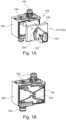
- Fig. 1A shows a solenoid assembly according to an embodiment of the present invention.
- the solenoid assembly includes a valve unit 110 with one or more solenoid valves and a first connector assembly 121, which is selected from a plurality of connector assemblies 120.
- the solenoid assembly further includes a plurality of valve connections 140 which provide, for example, pneumatic or hydraulic lines or represents an exhaust port for the integrated solenoid valve(s).
- the valve unit 110 comprises further a housing 180 which provides openings for the valve connections 140.
- the first connector assembly 121 comprises a first plug connection 125 with contacts 123 and is detachably mounted on one side of the housing 180 providing a cover or lid for the one side of the housing 180.
- the first connector assembly 121 further includes a printed circuit board 130 (not visible in Fig. 1A ) which is mounted to or integrated in the connector assembly 121 and is connected to the contacts 124 of the plug connection 125.
- the connector assembly 121 is detachably mounted to the housing 180 of the valve unit 110 by screw connections 128 which secure the connector assembly 121 to the housing 180. It is understood that the screw connection 128 is only one possibility to detachably or releasable mount of the connector assembly 121 to the valve unit 110. Further embodiments include other or additional detachable connections.
- the printed circuit board, PCB 130 acts as a connector interface allowing various connector assemblies 120 to be connected to the valve unit 110.
- the PCB 130 includes a contact structure that - when mounting the (first) connector assembly 121 to the housing 180 - electrically connects the solenoid valves and the printed circuit board 130 in the first connector assembly 121.
- This contact structure provides a releasable electrical connection and may comprise at least one of the following: a contact pin, a spring contact, a plug, a clamp, a terminal, a contact pad.
- Fig. 1B shows the valve unit 110 without the first connector assembly 121 but with further details such as the electrical wiring or contact strips 112 and contact pins 114 for electrically contacting the solenoid valve(s) integrated in the valve unit 110.
- the valve pins 114 are connected to the contact strips 112 and are configured to protrude from a side of the valve unit 110. Therefore, when mounting the first connector assembly 121 onto the valve unit 110, the valve pins 114 will contact the printed circuit board 130 in the first connector assembly 121.
- PCB 130 may comprise corresponding openings into which valve pins 114 can be inserted.
- valve pins 114 can be replaced by spring contacts that - upon mounting the connector assembly 121 onto the valve unit 110 - will get in touch with exemplary contact pads provided on the PCB 130. It is understood that any kind of releasable contact structure 130 may be implemented as interface to establish a releasable electrical contact between the valve unit 110 and the PCB 130 in connector assembly 121.
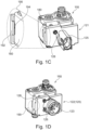
- Fig. 1C shows the solenoid assembly according to another embodiment, wherein the detachable mounting of the first connector assembly 121 to the valve unit 110 is achieved by using a snap-fit connection 190 in combination with a screw connection 180.
- the snap-fit connection 190 (see enlarged view) includes a protrusion 192 acting as a grab portion to engage a recess 194 in the housing 180 of valve unit 110.
- a same snap-fit connection 190 or a releasable hinge may be formed at the opposite side of the first connector assembly 121 to fix the first connector assembly 121 on two opposite sides to the housing 180.
- the screw connection 128 can be utilized to further secure the connection between the valve unit 110 and the first connector assembly 121. According to this embodiment only a single screw connection 128 is utilized, because the snap-fit connection 190 provides already a fixation.
- the first connector assembly 121 was selected from a plurality of connector assemblies 120 to provide different plug connections 125, 126, which are not interchangeably usable.
- Figs. 1A and 1C showed a first plug connection 125.
- Fig. 1D shows another embodiment, wherein a second connector assembly 122 is mounted to the valve unit 110, for which, again, a snap-fit connection 190 may be utilized.
- the second connector assembly 122 includes the second plug connection126 which has a circular plug, whereas the first connector assembly 121 as shown in Figs. 1A and 1C with the first plug connection125 has an oval plug.
- there are different oval plug connections 125 and/or different circular plug connections 126 wherein none of them are compatible with other ones. It is understood that any kind of plug connections can be utilized for the connector assemblies 120.
- Fig. 2A shows the solenoid assembly according to another embodiment, wherein the valve unit 110 is connected to the second connector assembly 122 providing the exemplary circular, second plug connection 126.
- the PCB 130 is included in the valve unit 110 and not in the connector assembly 122 as in Figs. 1A-1D .
- the detachable connection between the second connector assembly 122 to the valve unit 110 can be made by a screw connection 128 and/or by a snap-fit connection as described in Figs. 1C and 1D .
- the second connector assembly 122 is only fixed to the valve unit 110 using a screw connection 180, two screw connection can be utilized at different location (e.g. on diametrically opposite sides of the plug connection 126), whereas for an snap-fit or press-fit connection, only one or none screw connection 128 might be used.
- Fig. 2B shows the valve unit 110 of the embodiment of Fig. 2A with the exposed printed circuit board 130 covering one side of the valve unit 110 and being mounted to the housing 180 of the valve unit 110.
- the printed circuit board 130 includes a contact structure 133 with, e.g., three openings to receive three contact pins (not visible in Fig. 2B ) of the second plug assembly 122 when mounting the plug assembly 122 to the valve assembly 110.
- the contact structure 133 may be formed by spring contacts or contact pads to provide a releasable contact between the printed circuit board 130 and the plug assembly 122.
- the exemplary contact pins are in electrical contact with the contacts 123 of the plug assembly 122 (see Fig. 2A ).
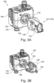
- Figs. 3A and 3B illustrate the solenoid assembly according to yet another embodiment, where the printed circuit board 130 is integrated into the housing 180 of the valve unit 110.
- the valve unit 110 or its housing 180 provides an opening 185 which exposes the three opening 133 of the PCB 130 (see Fig. 2B ) for establishing the connection with the connector assemblies 120.
- the selected connector assembly 120 is the first connector assembly 121 (with an oval plug 125), whereas in Fig. 3B the selected connector assembly 120 is the second connector assembly 122 (with a circular plug 126).
- the connector assembly 120 can be freely selected (e.g., depending on demands or wishes of customers).
- all connector assemblies 120 are configured to fit to the valve unit 110, i.e. they have universal or compatible means for connection.
- the connector assemblies 121, 122 are selected from the plurality of different connector assemblies 120 and are not compatible with each other so that the solenoid assembly can be manufactured allowing a wide range of different applications.
- arbitrary plug connections can be implemented for receiving respective electrical signals for the solenoid valve.
- the mounting of the connector assemblies 121, 122 to the valve unit 110 can be provided by a screw connection 128 or any other detachable connection (e.g. by a clip connection, press-fit connection, snap-fit connection etc.).
- the connector assemblies 121, 122 may include two, three or more contact pins that are introduced in openings 133 of the printed circuit board 130 where they are electrically contacted, e.g. by spring contacts.
- the contact pins may be portion of the contact 123 of the plug connections 125, 126 or may be separate pins that are electrically connected to the contacts 123 of the plug connections 125, 126.
- the electrical connection by pins engaging openings in the PCB 130 can be replaced by spring contracts touching contact pads on the PCB 130 or any other releasable electrical contact.
- the PCB 130 includes electronic components such as at least one chip or processing unit to process the electrical signals received by the connector assembly 120 and to generate control signals for controlling the valve unit 110.
- the solenoid valve unit 110 and the connector assemblies 120 can be manufactured separately and mounted together as a final manufacturing step (e.g. using a snap connection or clip connection or screw connection).
- Fig. 4 shows a schematic flow chart for a method for manufacturing a solenoid assembly. The method comprises:
- the valve unit 110 or the selected connector assembly 121, 122 may include a printed circuit board 130 with electronic components configured to process the electrical signals received by the plug connection 125, 126 and to generate control signals for controlling the solenoid valve.
- Embodiments provide the advantage that the solenoid assembly provides a modular concept for utilizing various plug connectors 125, 126 for a given valve unit 110, which can easily be replaced - even in the field.
- a universal valve unit 110 can be provided with a universal connection arrangement fitting for a plurality of different plug assemblies 120.
- the universal connection arrangement may include predefined positions for the screws or the snap-fit connection or the openings in CPB 130 or other predefined connection means.
- Embodiments can be used in various applications such as anti-lock braking system or pressure control valves or any other valve unit in trucks or other utility vehicles.
Landscapes
- Engineering & Computer Science (AREA)
- Physics & Mathematics (AREA)
- Electromagnetism (AREA)
- General Engineering & Computer Science (AREA)
- Power Engineering (AREA)
- Mechanical Engineering (AREA)
- Manufacturing & Machinery (AREA)
- Magnetically Actuated Valves (AREA)
Priority Applications (3)
| Application Number | Priority Date | Filing Date | Title |
|---|---|---|---|
| EP23169948.9A EP4456094A1 (de) | 2023-04-26 | 2023-04-26 | Solenoidanordnung und verfahren zu deren herstellung |
| US18/637,840 US20240360916A1 (en) | 2023-04-26 | 2024-04-17 | Solenoid assembly and a method for its manufacturing |
| CN202410512012.6A CN118867774A (zh) | 2023-04-26 | 2024-04-26 | 电磁线圈组件及其制造方法 |
Applications Claiming Priority (1)
| Application Number | Priority Date | Filing Date | Title |
|---|---|---|---|
| EP23169948.9A EP4456094A1 (de) | 2023-04-26 | 2023-04-26 | Solenoidanordnung und verfahren zu deren herstellung |
Publications (1)
| Publication Number | Publication Date |
|---|---|
| EP4456094A1 true EP4456094A1 (de) | 2024-10-30 |
Family
ID=86226572
Family Applications (1)
| Application Number | Title | Priority Date | Filing Date |
|---|---|---|---|
| EP23169948.9A Pending EP4456094A1 (de) | 2023-04-26 | 2023-04-26 | Solenoidanordnung und verfahren zu deren herstellung |
Country Status (3)
| Country | Link |
|---|---|
| US (1) | US20240360916A1 (de) |
| EP (1) | EP4456094A1 (de) |
| CN (1) | CN118867774A (de) |
Citations (4)
| Publication number | Priority date | Publication date | Assignee | Title |
|---|---|---|---|---|
| JPH1047522A (ja) * | 1996-08-06 | 1998-02-20 | Ckd Corp | 電磁弁の給電装置 |
| US20040051069A1 (en) * | 2002-09-17 | 2004-03-18 | Smc Corporation | Solenoid valve with terminal box |
| EP2110562B1 (de) * | 2008-04-15 | 2011-05-04 | FESTO AG & Co. KG | Ventilanordnung |
| US20210265794A1 (en) * | 2018-11-08 | 2021-08-26 | Woco Industrietechnik Gmbh | Plug adapter for docking onto a solenoid valve |
-
2023
- 2023-04-26 EP EP23169948.9A patent/EP4456094A1/de active Pending
-
2024
- 2024-04-17 US US18/637,840 patent/US20240360916A1/en active Pending
- 2024-04-26 CN CN202410512012.6A patent/CN118867774A/zh active Pending
Patent Citations (4)
| Publication number | Priority date | Publication date | Assignee | Title |
|---|---|---|---|---|
| JPH1047522A (ja) * | 1996-08-06 | 1998-02-20 | Ckd Corp | 電磁弁の給電装置 |
| US20040051069A1 (en) * | 2002-09-17 | 2004-03-18 | Smc Corporation | Solenoid valve with terminal box |
| EP2110562B1 (de) * | 2008-04-15 | 2011-05-04 | FESTO AG & Co. KG | Ventilanordnung |
| US20210265794A1 (en) * | 2018-11-08 | 2021-08-26 | Woco Industrietechnik Gmbh | Plug adapter for docking onto a solenoid valve |
Also Published As
| Publication number | Publication date |
|---|---|
| CN118867774A (zh) | 2024-10-29 |
| US20240360916A1 (en) | 2024-10-31 |
Similar Documents
| Publication | Publication Date | Title |
|---|---|---|
| EP0625287B1 (de) | Mehrschichtiger verbinder für integrierte mikrowellenschaltungsmodule | |
| US4820174A (en) | Modular connector assembly and filtered insert therefor | |
| CN109546381B (zh) | 卡连接器、卡座及终端 | |
| EP0791234B1 (de) | Luftfahrttechnische schnittstellenverteilereinheit | |
| US5472349A (en) | Surface mountable board edge connector | |
| JPH08330032A (ja) | 基板用コネクタ | |
| JPH03148198A (ja) | 基本回路カード組立体 | |
| US20090298541A1 (en) | Stacking type sim card connector and mobile terminal having the same | |
| US20070015410A1 (en) | Telecommunications connector with modular element | |
| EP4456094A1 (de) | Solenoidanordnung und verfahren zu deren herstellung | |
| US7632118B2 (en) | Adapter | |
| KR101647036B1 (ko) | 인쇄회로기판용 플러그-인 커넥터 | |
| US20010014554A1 (en) | Card connector | |
| WO1999054973A1 (en) | Quick connect relay module | |
| JPH05114440A (ja) | プログラマブル部材を有するコネクタ組立部品 | |
| US7044745B2 (en) | Electronic device | |
| EP4030876B1 (de) | Substrateinheit und verfahren zur herstellung einer substrateinheit | |
| US4514022A (en) | Probe cable assemblies | |
| US20040165341A1 (en) | Electronic units and connections | |
| US7525221B2 (en) | Connection arrangement for connecting an electronic component and a power circuit of a control device | |
| KR101037762B1 (ko) | 알씨에이 핀잭 | |
| US6485112B1 (en) | Assembly, with lead frame, for antilock brake system and associated method | |
| US20020072276A1 (en) | Multilayer connector for electronic signals | |
| KR101977751B1 (ko) | 제어기 모듈을 포함하는 전자 제어 장치 | |
| EP4489416A1 (de) | Sensoreinheit mit walzenverstellbarem gehäuse und verfahren zu deren montage |
Legal Events
| Date | Code | Title | Description |
|---|---|---|---|
| PUAI | Public reference made under article 153(3) epc to a published international application that has entered the european phase |
Free format text: ORIGINAL CODE: 0009012 |
|
| STAA | Information on the status of an ep patent application or granted ep patent |
Free format text: STATUS: THE APPLICATION HAS BEEN PUBLISHED |
|
| AK | Designated contracting states |
Kind code of ref document: A1 Designated state(s): AL AT BE BG CH CY CZ DE DK EE ES FI FR GB GR HR HU IE IS IT LI LT LU LV MC ME MK MT NL NO PL PT RO RS SE SI SK SM TR |
|
| STAA | Information on the status of an ep patent application or granted ep patent |
Free format text: STATUS: REQUEST FOR EXAMINATION WAS MADE |
|
| 17P | Request for examination filed |
Effective date: 20250430 |