EP4456074A1 - Feed mechanism and method for manufacturing same - Google Patents
Feed mechanism and method for manufacturing same Download PDFInfo
- Publication number
- EP4456074A1 EP4456074A1 EP22910973.1A EP22910973A EP4456074A1 EP 4456074 A1 EP4456074 A1 EP 4456074A1 EP 22910973 A EP22910973 A EP 22910973A EP 4456074 A1 EP4456074 A1 EP 4456074A1
- Authority
- EP
- European Patent Office
- Prior art keywords
- feed screw
- movable body
- torque generation
- generation member
- base
- Prior art date
- Legal status (The legal status is an assumption and is not a legal conclusion. Google has not performed a legal analysis and makes no representation as to the accuracy of the status listed.)
- Pending
Links
Images





Classifications
-
- G—PHYSICS
- G12—INSTRUMENT DETAILS
- G12B—CONSTRUCTIONAL DETAILS OF INSTRUMENTS, OR COMPARABLE DETAILS OF OTHER APPARATUS, NOT OTHERWISE PROVIDED FOR
- G12B5/00—Adjusting position or attitude, e.g. level, of instruments or other apparatus, or of parts thereof; Compensating for the effects of tilting or acceleration, e.g. for optical apparatus
-
- F—MECHANICAL ENGINEERING; LIGHTING; HEATING; WEAPONS; BLASTING
- F16—ENGINEERING ELEMENTS AND UNITS; GENERAL MEASURES FOR PRODUCING AND MAINTAINING EFFECTIVE FUNCTIONING OF MACHINES OR INSTALLATIONS; THERMAL INSULATION IN GENERAL
- F16B—DEVICES FOR FASTENING OR SECURING CONSTRUCTIONAL ELEMENTS OR MACHINE PARTS TOGETHER, e.g. NAILS, BOLTS, CIRCLIPS, CLAMPS, CLIPS OR WEDGES; JOINTS OR JOINTING
- F16B25/00—Screws that cut thread in the body into which they are screwed, e.g. wood screws
- F16B25/0036—Screws that cut thread in the body into which they are screwed, e.g. wood screws characterised by geometric details of the screw
-
- F—MECHANICAL ENGINEERING; LIGHTING; HEATING; WEAPONS; BLASTING
- F16—ENGINEERING ELEMENTS AND UNITS; GENERAL MEASURES FOR PRODUCING AND MAINTAINING EFFECTIVE FUNCTIONING OF MACHINES OR INSTALLATIONS; THERMAL INSULATION IN GENERAL
- F16B—DEVICES FOR FASTENING OR SECURING CONSTRUCTIONAL ELEMENTS OR MACHINE PARTS TOGETHER, e.g. NAILS, BOLTS, CIRCLIPS, CLAMPS, CLIPS OR WEDGES; JOINTS OR JOINTING
- F16B33/00—Features common to bolt and nut
- F16B33/02—Shape of thread; Special thread-forms
-
- F—MECHANICAL ENGINEERING; LIGHTING; HEATING; WEAPONS; BLASTING
- F16—ENGINEERING ELEMENTS AND UNITS; GENERAL MEASURES FOR PRODUCING AND MAINTAINING EFFECTIVE FUNCTIONING OF MACHINES OR INSTALLATIONS; THERMAL INSULATION IN GENERAL
- F16H—GEARING
- F16H25/00—Gearings comprising primarily only cams, cam-followers and screw-and-nut mechanisms
- F16H25/18—Gearings comprising primarily only cams, cam-followers and screw-and-nut mechanisms for conveying or interconverting oscillating or reciprocating motions
- F16H25/20—Screw mechanisms
- F16H25/2003—Screw mechanisms with arrangements for taking up backlash
- F16H25/2006—Screw mechanisms with arrangements for taking up backlash with more than one nut or with nuts consisting of more than one bearing part
Definitions
- the present invention relates to a feed mechanism that moves a movable body with a feed screw.
- a feed mechanism includes a base, a movable body, and a feed screw that moves the movable body relative to the base, and is configured in such a manner that the movable body moves by rotating the feed screw.
- the feed mechanism may be desired to prevent the movable body from moving after the position of the movable body is adjusted.
- a laser displacement sensor, a CCD camera, an optical device, a sensor, and the like are mounted on the movable body, it is desired to prevent them from moving after their positions are adjusted with the feed screw.
- Patent Literature 1 discloses a feed mechanism in which two nuts, that is, a main nut and a secondary nut, are threadedly engaged with a feed screw, an elastic body such as a spring is placed between the main nut and the secondary nut, and the main nut and the secondary nut are biased in opposite directions by the elastic body.
- the main nut and the secondary nut are biased in opposite directions by the elastic body. Therefore, when the feed screw is rotated, the main nut and the secondary nut generate torque that resists the rotation of the feed screw. Hence, when the feed screw is rotated manually, the feed screw can be prevented from rotating lightly, which allows fine adjustment of the amount of rotation of the feed screw. Moreover, the feed screw can be prevented from rotating after the position adjustment, which can prevent the movable body from moving.
- Patent Literature 1 JP H10-047451 A
- Patent Literature 1 has problems that the number of parts increases and that the feed mechanism is not suitable for downsizing.
- the present invention has been made in view of the above problems, and an object of the present invention is to provide a feed mechanism that has a small number of parts and that is suitable for downsizing.
- one aspect of the present invention is a feed mechanism including: a base; a movable body; a feed screw configured to move the movable body relative to the base; and a torque generation member formed with a female thread that is threadedly engaged with the feed screw, in which one of the movable body and the base is formed with a housing hole extending in a direction orthogonal to the feed screw, and the torque generation member is housed in the housing hole.
- the torque generation member it is possible to prevent the torque generation member from being displaced in an axial direction of the feed screw relative to the one of the movable body and the base. Torque is generated on the feed screw by use of the torque generation member, so that it is possible to obtain a feed mechanism that has a small number of parts and that is suitable for downsizing.
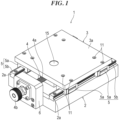
- Fig. 1 illustrates a perspective view of a feed mechanism 1 according to a first embodiment of the present invention.
- Fig. 2 illustrates a cross-sectional view taken along a feed screw 4 of the feed mechanism 1.
- Fig. 3 illustrates an exploded perspective view of the feed mechanism 1.
- the feed mechanism 1 includes a base 2, a movable body 3, and the feed screw 4.
- the feed mechanism 1 is also called a table device, a stage device, or the like.
- the base 2 has a flat plate shape.
- the planar shape of the base 2 is not particularly limited, and is, for example, a quadrangle.
- the base 2 is mounted on a fixed-side member such as a frame.
- the base 2 is formed with a mounting hole (not illustrated) for fastening the base 2 to the fixed-side member with a fastening member such as a bolt.
- the material of the base 2 is not particularly limited, and is, for example, metal such as aluminum, or resin.
- a guide mechanism for guiding linear motion of the movable body 3 relative to the base 2 is mounted on a top surface of the base 2.
- the configuration of the guide mechanism is not particularly limited, and is, for example, a linear guide or a cross roller guide.
- a pair of the linear guides 5 is illustrated by example in Fig. 1 .
- Each of the linear guides 5 includes a rail 5b that is fixed to the top surface of the base 2, and blocks 5a and 5a that are movable along the rail 5b.
- the movable body 3 is mounted on the blocks 5a.
- the rails 5b abut on protruding walls 2a at both left and right ends of the top surface of the base 2 to maintain parallelism.
- Many unillustrated rolling elements such as balls or rollers are interposed between the rail 5b and the block 5a in such a manner as to be able to perform rolling motion. Since the configuration of the linear guides 5 is well known, further detailed description is omitted.
- the feed screw 4 is rotatably supported by the base 2.
- the feed screw 4 is formed with a male thread 4a.
- the type of the male thread 4a is not particularly limited, and may be a triangular screw thread or a trapezoidal screw thread.
- One end of the feed screw 4 is provided with a head 4b, so that the feed screw 4 can be rotated manually.
- the feed screw 4 may be rotated by use of a hexagon wrench or a screwdriver, or the feed screw 4 may be rotated automatically by use of a motor.
- the material of the feed screw 4 is not particularly limited, and is, for example, metal such as steel.
- a bearing holder 6 is mounted on an end surface of the base 2.
- the bearing holder 6 houses a bearing 7 that rotatably supports the feed screw 4.
- a reference sign 8 denotes an outer ring retainer for fixing an outer ring of the bearing 7 to the bearing holder 6.
- a reference sign 9 denotes an inner ring retainer for fixing an inner ring of the bearing 7 to the feed screw 4.
- the inner ring retainer 9 is formed with a female thread that is threadedly engaged with an inner ring retainer-specific male thread (not illustrated) of the feed screw 4.
- the movable body 3 includes, for example, a flat plate-shaped main body portion 3a, and a housing portion 3b protruding from the main body portion 3a toward the base 2.
- the main body portion 3a and the housing portion 3b are integrally formed.
- the planar shape of the main body portion 3a is, for example, a quadrangle.
- the main body portion 3a is formed with mounting holes 11 for fixing the movable body 3 to the linear guides 5.
- the main body portion 3a is formed with fixing screws (not illustrated) for fixing a laser displacement sensor, a CCD camera, an optical device, a sensor, and the like.
- the material of the movable body 3 is not particularly limited, and is, for example, metal such as aluminum, or resin.
- the housing portion 3b of the movable body 3 is formed with a housing hole 12 extending in a direction orthogonal to the feed screw 4.
- the housing hole 12 has a circular shape in cross section and penetrates the housing portion 3b of the movable body 3 in an up-and-down direction.
- a center line 12a of the housing hole 12 is orthogonal to the feed screw 4.
- the movable body 3 is formed with a female thread 13 that is threadedly engaged with the feed screw 4.
- the female thread 13 is adjacent to the housing hole 12.
- the type of the female thread 13 is not particularly limited, and is a triangular screw thread, a trapezoidal screw thread, or the like, as with the feed screw 4.
- the female thread 13 of the movable body 3 is threadedly engaged with the feed screw 4. Therefore, the movable body 3 moves in an axial direction of the feed screw 4 by rotating the feed screw 4.
- the housing portion 3b of the movable body 3 is formed with a clearance hole 14 on a side opposite to the female thread 13 across the housing hole 12.
- the inner diameter of the clearance hole 14 is larger than the outer diameter of the feed screw 4.
- a torque generation member 15 is inserted into the housing hole 12 of the movable body 3.
- the torque generation member 15 is exposed on a surface of the movable body 3.
- the torque generation member 15 has an approximately cylindrical shape, and a center line 15c of the torque generation member 15 is orthogonal to the feed screw 4.
- the material of the torque generation member 15 is resin, rubber, or the like, and the torque generation member 15 is an elastic body.
- the torque generation member 15 may be simply inserted into the housing hole 12 of the movable body 3, or may be fixed to the housing hole 12 with an adhesive.
- a through-hole 15a is formed in the torque generation member 15.
- the through-hole 15a is not formed with a female thread.
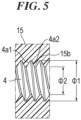
- the diameter of the through-hole 15a is smaller than an outer diameter ⁇ 1 (refer to Fig. 5 ) of the crests of the feed screw 4, and is desirably smaller than a diameter ⁇ 2 of the roots of the feed screw 4.
- a female thread 15b is generated, for example, rolled, on an inner surface of the torque generation member 15 by use of the feed screw 4.
- the feed screw 4 is threadedly engaged with the female thread 13 of the movable body 3.
- the tip of the feed screw 4 reaches the through-hole 15a of the torque generation member 15 by rotating the feed screw 4.
- the torque generation member 15 is plastically deformed, and the female thread 15b is rolled on an inner surface of the through-hole 15a.
- an incomplete crest may be formed in advance on the inner surface of the through-hole 15a to facilitate thread rolling.
- the female thread 15b instead of rolling the female thread 15b on the inner surface of the torque generation member 15 by use of the feed screw 4, the female thread 15b to have an interference fit (that is, a negative gap) with the feed screw 4 may be formed in advance on the inner surface of the through-hole 15a.
- the entire circumference of the female thread 15b is formed in the torque generation member 15.
- the female thread 15b of the torque generation member 15 is in intimate contact with flanks 4a1 and 4a2 on two sides of the crest of the feed screw 4 without any gap.
- the torque generation member 15 generates torque that resists the rotation of the feed screw 4.
- the torque generation member 15 can prevent the feed screw 4 from rotating lightly, which allows fine adjustment of the amount of rotation of the feed screw 4.
- the torque generation member 15 also has a role of absorbing backlash between the female thread 13 of the movable body 3 and the feed screw 4. In other words, it also has a role of removing the rattling of the movable body 3 caused by backlash.
- the position of the movable body 3 is determined by the torque generation member 15 that is in intimate contact with the feed screw 4 without any gap. When an axial force is applied to the movable body 3, the torque generation member 15 is elastically deformed by the backlash.
- the movable body 3 is formed with the housing hole 12 extending in the direction orthogonal to the feed screw 4, and the torque generation member 15 is housed in the housing hole 12. Therefore, it is possible to prevent the torque generation member 15 from being displaced in the axial direction of the feed screw 4 relative to the movable body 3.
- the torque generation member 15 is used to generate torque on the feed screw 4, so that it is possible to obtain the feed mechanism 1 that has a small number of parts and is suitable for downsizing. Moreover, if the torque generation function is weakened due to the wearing out of the torque generation member 15 over time, the torque generation member 15 can be easily replaced. Therefore, predetermined performance can be maintained.
- the movable body 3 is formed with the female thread 13 that is threadedly engaged with the feed screw 4. Therefore, the movable body 3 can be stably moved by use of the female thread 13 of the movable body 3. Moreover, the female thread 13 of the movable body 3 can also be used as a thrust source to generate the female thread 15b in the torque generation member 15 by use of the feed screw 4.
- the female thread 15b is generated in the torque generation member 15 by use of the feed screw 4. Therefore, the torque generation member 15 can be brought into intimate contact with the feed screw 4. Moreover, the torque generation member 15 expands due to the threading. Therefore, the torque generation member 15 can be brought into intimate contact with an inner surface of the housing hole 12 of the movable body 3.
- the torque generation member 15 has an approximately cylindrical shape. Therefore, the attitude of the torque generation member 15 can be changed following the feed screw 4, or the torque generation member 15 can be partially deformed following the feed screw 4. Hence, it is possible to suppress the fluctuations of torque acting on the feed screw 4.
- the torque generation member 15 is exposed on the surface of the movable body 3. Therefore, the replacement of the torque generation member 15 is easy.
- the present invention is not limited to concretization of the above embodiment, and can be concretized in other embodiments without changing the gist of the present invention.
- the main body portion 3a and the housing portion 3b of the movable body 3 are integrally formed. However, they may be separate portions and fastened together with a fastening member such as a bolt.
- Fig. 6 illustrates a cross-sectional view of a feed mechanism 21 according to a second embodiment of the present invention.
- Fig. 7 illustrates an exploded perspective view of the feed mechanism 21 according to the second embodiment of the present invention.
- the feed mechanism 21 according to the second embodiment includes a base 2, a movable body 3, a feed screw 4, and a torque generation member 15.
- the feed screw 4 is rotatably supported by the base 2, and the movable body 3 moves in the axial direction of the feed screw 4 relative to the base 2 by rotating the feed screw 4.
- the feed screw 4 is rotatably supported by the movable body 3, and the feed screw 4 and the movable body 3 move in the axial direction of the feed screw 4 relative to the base 2 by rotating the feed screw 4.
- the base 2 has a flat plate shape.
- the planar shape of the base 2 is not particularly limited, and is, for example, a quadrangle.
- a pair of guide members 22 for guiding linear motion of the movable body 3 relative to the base 2 is mounted on a top surface of the base 2.
- the guide members 22 are fixed in long holes 2b in the top surface of the base 2.
- An undersurface of the movable body 3 is formed with guide grooves (not illustrated) where the guide members 22 enter.
- the movable body 3 slides along the guide members 22.
- One side of the base 2 is formed with a notch 2c.
- the notch 2c forms a space for moving a coupling portion 23.
- the coupling portion 23 is fixed to the movable body 3.
- the coupling portion 23 is fastened to an end surface of the movable body 3 with a fastening member 24 such as a bolt.
- the feed screw 4 is rotatably supported by the coupling portion 23.
- the coupling portion 23 is sandwiched between a head 4b of the feed screw 4 and a nut 25. When the feed screw 4 moves in the axial direction, the movable body 3, together with the coupling portion 23, moves in the axial direction.
- the feed screw 4 is formed with a male thread 4a.
- One end of the feed screw 4 is provided with a head 4b, so that the feed screw 4 can be rotated manually.
- the feed screw 4 may be rotated by use of a hexagon wrench or a screwdriver, or the feed screw 4 may be rotated automatically by use of a motor.
- the movable body 3 has, for example, a flat plate shape.
- the movable body 3 is formed with fixing screws 3c for fixing a laser displacement sensor, a CCD camera, an optical device, a sensor, and the like to the movable body 3.
- the movable body 3 is formed with an access hole 27 at a position corresponding to a housing hole 26 of the base 2 to allow access to the torque generation member 15 housed in the housing hole 26 of the base 2.
- a reference sign 28 denotes a fastening member for preventing the movable body 3 from being detached from the base 2.
- the base 2 is formed with a long hole 29 where the fastening member 28 enters.
- the movable body 3 is formed with a screw hole 30 that is threadedly engaged with the fastening member 28.
- the fastening member 28 also has a role of bringing the movable body 3 and the base 2 into intimate contact with each other and generating a force that resists sliding of the movable body 3.
- the base 2 is formed with the housing hole 26 extending in a direction orthogonal to the feed screw 4.
- the housing hole 26 has a circular shape in cross section, and penetrates the base 2 in an up-and-down direction.
- a center line 26a of the housing hole 26 is orthogonal to the feed screw 4.
- the base 2 is formed with a female thread 31 that is threadedly engaged with the feed screw 4.
- the female thread 31 is adjacent to the housing hole 26.
- the female thread 31 of the base 2 is threadedly engaged with the feed screw 4. Therefore, the movable body 3, together with the feed screw 4, moves in the axial direction of the feed screw 4 by rotating the feed screw 4.
- the base 2 is formed with a clearance hole 32 on a side opposite to the female thread 31 across the housing hole 26.
- the torque generation member 15 is inserted into the housing hole 26 of the base 2.
- the torque generation member 15 has an approximately cylindrical shape, and a center line of the torque generation member 15 is orthogonal to the feed screw 4.
- the material of the torque generation member 15 is resin, rubber, or the like, and the torque generation member 15 is an elastic body.
- a female thread 15b that is threadedly engaged with the feed screw 4 is generated in the torque generation member 15 by use of the feed screw 4.
- a method for generating the female thread 15b is the same as that of the feed mechanism 1 according to the first embodiment.
- the female thread 15b of the torque generation member 15 is in intimate contact with the feed screw 4 without any gap.
- the torque generation member 15 generates torque that resists the rotation of the feed screw 4.
- the torque generation member 15 can prevent the feed screw 4 from rotating lightly, which allows fine adjustment of the amount of rotation of the feed screw 4.
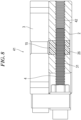
- Fig. 8 illustrates a modification 41 of the feed mechanism 21 according to the second embodiment.
- the base 2 is formed with the clearance hole 32 on the side opposite to the female thread 31 across the housing hole 26.
- the base 2 is formed with a female thread 42 that is threadedly engaged with the feed screw 4, instead of the clearance hole, on the side opposite to the female thread 31 across the housing hole 26.
- the other configurations are the same as those of the feed mechanism 21 according to the second embodiment. Therefore, the same reference signs are assigned, and descriptions thereof are omitted.
- Fig. 9 illustrates a modification 51 of the feed mechanism 21 according to the second embodiment.
- the base 2 is formed with the female thread 31 adjacent to the housing hole 26.
- the base 2 is formed with a clearance hole 43 adjacent to the housing hole 26.
Landscapes
- Engineering & Computer Science (AREA)
- General Engineering & Computer Science (AREA)
- Mechanical Engineering (AREA)
- Physics & Mathematics (AREA)
- Geometry (AREA)
- Transmission Devices (AREA)
- Details Of Measuring And Other Instruments (AREA)
Abstract
Description
- The present invention relates to a feed mechanism that moves a movable body with a feed screw.
- A feed mechanism includes a base, a movable body, and a feed screw that moves the movable body relative to the base, and is configured in such a manner that the movable body moves by rotating the feed screw.
- The feed mechanism may be desired to prevent the movable body from moving after the position of the movable body is adjusted. For example, if a laser displacement sensor, a CCD camera, an optical device, a sensor, and the like are mounted on the movable body, it is desired to prevent them from moving after their positions are adjusted with the feed screw.
- As this type of feed mechanism,
Patent Literature 1 discloses a feed mechanism in which two nuts, that is, a main nut and a secondary nut, are threadedly engaged with a feed screw, an elastic body such as a spring is placed between the main nut and the secondary nut, and the main nut and the secondary nut are biased in opposite directions by the elastic body. - The main nut and the secondary nut are biased in opposite directions by the elastic body. Therefore, when the feed screw is rotated, the main nut and the secondary nut generate torque that resists the rotation of the feed screw. Hence, when the feed screw is rotated manually, the feed screw can be prevented from rotating lightly, which allows fine adjustment of the amount of rotation of the feed screw. Moreover, the feed screw can be prevented from rotating after the position adjustment, which can prevent the movable body from moving.
- Patent Literature 1:
JP H10-047451 A - However, the feed mechanism described in
Patent Literature 1 has problems that the number of parts increases and that the feed mechanism is not suitable for downsizing. - The present invention has been made in view of the above problems, and an object of the present invention is to provide a feed mechanism that has a small number of parts and that is suitable for downsizing.
- In order to solve the above problems, one aspect of the present invention is a feed mechanism including: a base; a movable body; a feed screw configured to move the movable body relative to the base; and a torque generation member formed with a female thread that is threadedly engaged with the feed screw, in which one of the movable body and the base is formed with a housing hole extending in a direction orthogonal to the feed screw, and the torque generation member is housed in the housing hole.
- According to the present invention, it is possible to prevent the torque generation member from being displaced in an axial direction of the feed screw relative to the one of the movable body and the base. Torque is generated on the feed screw by use of the torque generation member, so that it is possible to obtain a feed mechanism that has a small number of parts and that is suitable for downsizing.
-
-
Fig. 1 is a perspective view of a feed mechanism according to a first embodiment of the present invention. -
Fig. 2 is a cross-sectional view taken along a feed screw of the feed mechanism according to the embodiment. -
Fig. 3 is an exploded perspective view of the feed mechanism according to the embodiment. -
Fig. 4 is a perspective view of a torque generation member according to the embodiment. -
Fig. 5 is a cross-sectional view illustrating an intimate contact state between the torque generation member and the feed screw according to the embodiment. -
Fig. 6 is a cross-sectional view taken along a feed screw of a feed mechanism according to a second embodiment of the present invention. -
Fig. 7 is an exploded perspective view of the feed mechanism according to the second embodiment of the present invention. -
Fig. 8 is a diagram illustrating a modification of the feed mechanism according to the second embodiment of the present invention. -
Fig. 9 is a diagram illustrating a modification of the feed mechanism according to the second embodiment of the present invention. - Embodiments of a feed mechanism according to the present invention are described in detail hereinafter with reference to the accompanying drawings. However, the feed mechanism according to the present invention can be embodied in various forms and is not limited to the embodiments described in the present description. The embodiments are provided with the intention of enabling those skilled in the art to fully understand the invention by fully disclosing the description.
-
Fig. 1 illustrates a perspective view of afeed mechanism 1 according to a first embodiment of the present invention.Fig. 2 illustrates a cross-sectional view taken along afeed screw 4 of thefeed mechanism 1.Fig. 3 illustrates an exploded perspective view of thefeed mechanism 1. - As illustrated in
Fig. 1 , thefeed mechanism 1 includes abase 2, amovable body 3, and thefeed screw 4. Thefeed mechanism 1 is also called a table device, a stage device, or the like. - The
base 2 has a flat plate shape. The planar shape of thebase 2 is not particularly limited, and is, for example, a quadrangle. Thebase 2 is mounted on a fixed-side member such as a frame. Thebase 2 is formed with a mounting hole (not illustrated) for fastening thebase 2 to the fixed-side member with a fastening member such as a bolt. The material of thebase 2 is not particularly limited, and is, for example, metal such as aluminum, or resin. - A guide mechanism for guiding linear motion of the
movable body 3 relative to thebase 2 is mounted on a top surface of thebase 2. The configuration of the guide mechanism is not particularly limited, and is, for example, a linear guide or a cross roller guide. A pair of thelinear guides 5 is illustrated by example inFig. 1 . Each of thelinear guides 5 includes arail 5b that is fixed to the top surface of thebase 2, andblocks rail 5b. Themovable body 3 is mounted on theblocks 5a. Therails 5b abut on protrudingwalls 2a at both left and right ends of the top surface of thebase 2 to maintain parallelism. Many unillustrated rolling elements such as balls or rollers are interposed between therail 5b and theblock 5a in such a manner as to be able to perform rolling motion. Since the configuration of thelinear guides 5 is well known, further detailed description is omitted. - The
feed screw 4 is rotatably supported by thebase 2. Thefeed screw 4 is formed with amale thread 4a. The type of themale thread 4a is not particularly limited, and may be a triangular screw thread or a trapezoidal screw thread. One end of thefeed screw 4 is provided with ahead 4b, so that thefeed screw 4 can be rotated manually. Note that thefeed screw 4 may be rotated by use of a hexagon wrench or a screwdriver, or thefeed screw 4 may be rotated automatically by use of a motor. The material of thefeed screw 4 is not particularly limited, and is, for example, metal such as steel. - As illustrated in
Fig. 2 , abearing holder 6 is mounted on an end surface of thebase 2. Thebearing holder 6 houses abearing 7 that rotatably supports thefeed screw 4. A reference sign 8 denotes an outer ring retainer for fixing an outer ring of thebearing 7 to thebearing holder 6. Areference sign 9 denotes an inner ring retainer for fixing an inner ring of thebearing 7 to thefeed screw 4. Theinner ring retainer 9 is formed with a female thread that is threadedly engaged with an inner ring retainer-specific male thread (not illustrated) of thefeed screw 4. - The
movable body 3 includes, for example, a flat plate-shapedmain body portion 3a, and ahousing portion 3b protruding from themain body portion 3a toward thebase 2. Themain body portion 3a and thehousing portion 3b are integrally formed. As illustrated inFig. 1 , the planar shape of themain body portion 3a is, for example, a quadrangle. Themain body portion 3a is formed with mountingholes 11 for fixing themovable body 3 to the linear guides 5. Moreover, themain body portion 3a is formed with fixing screws (not illustrated) for fixing a laser displacement sensor, a CCD camera, an optical device, a sensor, and the like. The material of themovable body 3 is not particularly limited, and is, for example, metal such as aluminum, or resin. - As illustrated in
Fig. 2 , thehousing portion 3b of themovable body 3 is formed with ahousing hole 12 extending in a direction orthogonal to thefeed screw 4. Thehousing hole 12 has a circular shape in cross section and penetrates thehousing portion 3b of themovable body 3 in an up-and-down direction. Acenter line 12a of thehousing hole 12 is orthogonal to thefeed screw 4. - The
movable body 3 is formed with afemale thread 13 that is threadedly engaged with thefeed screw 4. Thefemale thread 13 is adjacent to thehousing hole 12. The type of thefemale thread 13 is not particularly limited, and is a triangular screw thread, a trapezoidal screw thread, or the like, as with thefeed screw 4. Thefemale thread 13 of themovable body 3 is threadedly engaged with thefeed screw 4. Therefore, themovable body 3 moves in an axial direction of thefeed screw 4 by rotating thefeed screw 4. Thehousing portion 3b of themovable body 3 is formed with aclearance hole 14 on a side opposite to thefemale thread 13 across thehousing hole 12. The inner diameter of theclearance hole 14 is larger than the outer diameter of thefeed screw 4. - As illustrated in
Fig. 3 , atorque generation member 15 is inserted into thehousing hole 12 of themovable body 3. As illustrated inFig. 1 , thetorque generation member 15 is exposed on a surface of themovable body 3. Thetorque generation member 15 has an approximately cylindrical shape, and acenter line 15c of thetorque generation member 15 is orthogonal to thefeed screw 4. The material of thetorque generation member 15 is resin, rubber, or the like, and thetorque generation member 15 is an elastic body. Thetorque generation member 15 may be simply inserted into thehousing hole 12 of themovable body 3, or may be fixed to thehousing hole 12 with an adhesive. - As illustrated in
Fig. 4 , before thetorque generation member 15 is inserted into thehousing hole 12 of themovable body 3, a through-hole 15a is formed in thetorque generation member 15. The through-hole 15a is not formed with a female thread. The diameter of the through-hole 15a is smaller than an outer diameter Φ1 (refer toFig. 5 ) of the crests of thefeed screw 4, and is desirably smaller than a diameter Φ2 of the roots of thefeed screw 4. - As illustrated in
Fig. 2 , after thetorque generation member 15 is inserted into thehousing hole 12 of themovable body 3, afemale thread 15b is generated, for example, rolled, on an inner surface of thetorque generation member 15 by use of thefeed screw 4. Thefeed screw 4 is threadedly engaged with thefemale thread 13 of themovable body 3. The tip of thefeed screw 4 reaches the through-hole 15a of thetorque generation member 15 by rotating thefeed screw 4. When thefeed screw 4 is rotated further to screw the tip of thefeed screw 4 into the through-hole 15a of thetorque generation member 15, thetorque generation member 15 is plastically deformed, and thefemale thread 15b is rolled on an inner surface of the through-hole 15a. Note that an incomplete crest may be formed in advance on the inner surface of the through-hole 15a to facilitate thread rolling. Moreover, instead of rolling thefemale thread 15b on the inner surface of thetorque generation member 15 by use of thefeed screw 4, thefemale thread 15b to have an interference fit (that is, a negative gap) with thefeed screw 4 may be formed in advance on the inner surface of the through-hole 15a. - The entire circumference of the
female thread 15b is formed in thetorque generation member 15. As illustrated inFig. 5 , thefemale thread 15b of thetorque generation member 15 is in intimate contact with flanks 4a1 and 4a2 on two sides of the crest of thefeed screw 4 without any gap. When thefeed screw 4 is rotated, thetorque generation member 15 generates torque that resists the rotation of thefeed screw 4. Hence, when thefeed screw 4 is rotated manually, thetorque generation member 15 can prevent thefeed screw 4 from rotating lightly, which allows fine adjustment of the amount of rotation of thefeed screw 4. Moreover, after the position of themovable body 3 is adjusted, it is possible to prevent themovable body 3 from moving. - The
torque generation member 15 also has a role of absorbing backlash between thefemale thread 13 of themovable body 3 and thefeed screw 4. In other words, it also has a role of removing the rattling of themovable body 3 caused by backlash. The position of themovable body 3 is determined by thetorque generation member 15 that is in intimate contact with thefeed screw 4 without any gap. When an axial force is applied to themovable body 3, thetorque generation member 15 is elastically deformed by the backlash. - Up to this point, the configuration of the
feed mechanism 1 according to the embodiment has been described above. According to thefeed mechanism 1 of the embodiment, the following effects are exerted. - The
movable body 3 is formed with thehousing hole 12 extending in the direction orthogonal to thefeed screw 4, and thetorque generation member 15 is housed in thehousing hole 12. Therefore, it is possible to prevent thetorque generation member 15 from being displaced in the axial direction of thefeed screw 4 relative to themovable body 3. Thetorque generation member 15 is used to generate torque on thefeed screw 4, so that it is possible to obtain thefeed mechanism 1 that has a small number of parts and is suitable for downsizing. Moreover, if the torque generation function is weakened due to the wearing out of thetorque generation member 15 over time, thetorque generation member 15 can be easily replaced. Therefore, predetermined performance can be maintained. - The
movable body 3 is formed with thefemale thread 13 that is threadedly engaged with thefeed screw 4. Therefore, themovable body 3 can be stably moved by use of thefemale thread 13 of themovable body 3. Moreover, thefemale thread 13 of themovable body 3 can also be used as a thrust source to generate thefemale thread 15b in thetorque generation member 15 by use of thefeed screw 4. - The
female thread 15b is generated in thetorque generation member 15 by use of thefeed screw 4. Therefore, thetorque generation member 15 can be brought into intimate contact with thefeed screw 4. Moreover, thetorque generation member 15 expands due to the threading. Therefore, thetorque generation member 15 can be brought into intimate contact with an inner surface of thehousing hole 12 of themovable body 3. - The
torque generation member 15 has an approximately cylindrical shape. Therefore, the attitude of thetorque generation member 15 can be changed following thefeed screw 4, or thetorque generation member 15 can be partially deformed following thefeed screw 4. Hence, it is possible to suppress the fluctuations of torque acting on thefeed screw 4. - The
torque generation member 15 is exposed on the surface of themovable body 3. Therefore, the replacement of thetorque generation member 15 is easy. - Note that the present invention is not limited to concretization of the above embodiment, and can be concretized in other embodiments without changing the gist of the present invention.
- For example, in the above embodiment, the
main body portion 3a and thehousing portion 3b of themovable body 3 are integrally formed. However, they may be separate portions and fastened together with a fastening member such as a bolt. -
Fig. 6 illustrates a cross-sectional view of afeed mechanism 21 according to a second embodiment of the present invention.Fig. 7 illustrates an exploded perspective view of thefeed mechanism 21 according to the second embodiment of the present invention. - As with the
feed mechanism 1 according to the first embodiment, thefeed mechanism 21 according to the second embodiment includes abase 2, amovable body 3, afeed screw 4, and atorque generation member 15. - In the
feed mechanism 1 according to the first embodiment, thefeed screw 4 is rotatably supported by thebase 2, and themovable body 3 moves in the axial direction of thefeed screw 4 relative to thebase 2 by rotating thefeed screw 4. On the other hand, in thefeed mechanism 21 according to the second embodiment, thefeed screw 4 is rotatably supported by themovable body 3, and thefeed screw 4 and themovable body 3 move in the axial direction of thefeed screw 4 relative to thebase 2 by rotating thefeed screw 4. - As illustrated in
Fig. 7 , thebase 2 has a flat plate shape. The planar shape of thebase 2 is not particularly limited, and is, for example, a quadrangle. - A pair of
guide members 22 for guiding linear motion of themovable body 3 relative to thebase 2 is mounted on a top surface of thebase 2. Theguide members 22 are fixed inlong holes 2b in the top surface of thebase 2. An undersurface of themovable body 3 is formed with guide grooves (not illustrated) where theguide members 22 enter. Themovable body 3 slides along theguide members 22. One side of thebase 2 is formed with anotch 2c. Thenotch 2c forms a space for moving acoupling portion 23. - The
coupling portion 23 is fixed to themovable body 3. Thecoupling portion 23 is fastened to an end surface of themovable body 3 with afastening member 24 such as a bolt. Thefeed screw 4 is rotatably supported by thecoupling portion 23. Thecoupling portion 23 is sandwiched between ahead 4b of thefeed screw 4 and anut 25. When thefeed screw 4 moves in the axial direction, themovable body 3, together with thecoupling portion 23, moves in the axial direction. - The
feed screw 4 is formed with amale thread 4a. One end of thefeed screw 4 is provided with ahead 4b, so that thefeed screw 4 can be rotated manually. Note that thefeed screw 4 may be rotated by use of a hexagon wrench or a screwdriver, or thefeed screw 4 may be rotated automatically by use of a motor. - As illustrated in
Fig. 7 , themovable body 3 has, for example, a flat plate shape. Themovable body 3 is formed with fixingscrews 3c for fixing a laser displacement sensor, a CCD camera, an optical device, a sensor, and the like to themovable body 3. Moreover, themovable body 3 is formed with anaccess hole 27 at a position corresponding to ahousing hole 26 of thebase 2 to allow access to thetorque generation member 15 housed in thehousing hole 26 of thebase 2. - A
reference sign 28 denotes a fastening member for preventing themovable body 3 from being detached from thebase 2. Thebase 2 is formed with along hole 29 where thefastening member 28 enters. Themovable body 3 is formed with ascrew hole 30 that is threadedly engaged with thefastening member 28. Thefastening member 28 also has a role of bringing themovable body 3 and thebase 2 into intimate contact with each other and generating a force that resists sliding of themovable body 3. - As illustrated in
Fig. 6 , thebase 2 is formed with thehousing hole 26 extending in a direction orthogonal to thefeed screw 4. Thehousing hole 26 has a circular shape in cross section, and penetrates thebase 2 in an up-and-down direction. Acenter line 26a of thehousing hole 26 is orthogonal to thefeed screw 4. - The
base 2 is formed with afemale thread 31 that is threadedly engaged with thefeed screw 4. Thefemale thread 31 is adjacent to thehousing hole 26. Thefemale thread 31 of thebase 2 is threadedly engaged with thefeed screw 4. Therefore, themovable body 3, together with thefeed screw 4, moves in the axial direction of thefeed screw 4 by rotating thefeed screw 4. Thebase 2 is formed with aclearance hole 32 on a side opposite to thefemale thread 31 across thehousing hole 26. - The
torque generation member 15 is inserted into thehousing hole 26 of thebase 2. Thetorque generation member 15 has an approximately cylindrical shape, and a center line of thetorque generation member 15 is orthogonal to thefeed screw 4. The material of thetorque generation member 15 is resin, rubber, or the like, and thetorque generation member 15 is an elastic body. - A
female thread 15b that is threadedly engaged with thefeed screw 4 is generated in thetorque generation member 15 by use of thefeed screw 4. A method for generating thefemale thread 15b is the same as that of thefeed mechanism 1 according to the first embodiment. - The
female thread 15b of thetorque generation member 15 is in intimate contact with thefeed screw 4 without any gap. When thefeed screw 4 is rotated, thetorque generation member 15 generates torque that resists the rotation of thefeed screw 4. Hence, when thefeed screw 4 is rotated manually, thetorque generation member 15 can prevent thefeed screw 4 from rotating lightly, which allows fine adjustment of the amount of rotation of thefeed screw 4. Moreover, after the position of themovable body 3 is adjusted, it is possible to prevent themovable body 3 from moving. - Up to this point, the configuration of the feed mechanism according to the second embodiment has been described. The feed mechanism according to the second embodiment exerts substantially similar effects to those of the feed mechanism according to the first embodiment.
-
Fig. 8 illustrates amodification 41 of thefeed mechanism 21 according to the second embodiment. - In the
feed mechanism 21 according to the second embodiment, thebase 2 is formed with theclearance hole 32 on the side opposite to thefemale thread 31 across thehousing hole 26. In themodification 41, thebase 2 is formed with afemale thread 42 that is threadedly engaged with thefeed screw 4, instead of the clearance hole, on the side opposite to thefemale thread 31 across thehousing hole 26. The other configurations are the same as those of thefeed mechanism 21 according to the second embodiment. Therefore, the same reference signs are assigned, and descriptions thereof are omitted. -
Fig. 9 illustrates amodification 51 of thefeed mechanism 21 according to the second embodiment. - In the
feed mechanism 21 according to the second embodiment, thebase 2 is formed with thefemale thread 31 adjacent to thehousing hole 26. In thismodification 51, thebase 2 is formed with aclearance hole 43 adjacent to thehousing hole 26. The other configurations are the same as those of thefeed mechanism 21 according to the second embodiment. Therefore, the same reference signs are assigned, and descriptions thereof are omitted. - The present description is based on
Japanese Patent Application No. 2021-209024 filed on December 23, 2021 -
- 1
- Feed mechanism
- 2
- Base
- 3
- Movable body
- 4
- Feed screw
- 12
- Housing hole of movable body
- 13
- Female thread of movable body
- 15
- Torque generation member
- 15a
- Through-hole of torque generation member
- 15b
- Female thread of torque generation member
- 21
- Feed mechanism
- 26
- Housing hole of base
- 27
- Access hole of movable body
- 31
- Female thread of base
- 41
- Feed mechanism
- 51
- Feed mechanism
Claims (7)
- A feed mechanism comprising:a base;a movable body;a feed screw configured to move the movable body relative to the base; anda torque generation member formed with a female thread that is threadedly engaged with the feed screw, whereinone of the movable body and the base is formed with a housing hole extending in a direction orthogonal to the feed screw, and the torque generation member is housed in the housing hole.
- The feed mechanism according to claim 1, wherein one of the movable body and the base is formed with a female thread that is threadedly engaged with the feed screw.
- The feed mechanism according to claim 1 or 2, wherein the female thread is generated in the torque generation member by use of the feed screw.
- The feed mechanism according to any one of claims 1 to 3, wherein the torque generation member has an approximately cylindrical shape.
- The feed mechanism according to any one of claims 1 to 4, whereinthe movable body is formed with the housing hole in which the torque generation member is housed, andthe torque generation member is exposed on a surface of the movable body.
- The feed mechanism according to any one of claims 1 to 4, whereinthe base is formed with the housing hole in which the torque generation member is housed, andthe movable body is formed with an access hole accessible to the torque generation member.
- A method for manufacturing a feed mechanism including a base; a movable body; a feed screw configured to move the movable body relative to the base; and a torque generation member formed with a female thread that is threadedly engaged with the feed screw, the method comprising:inserting the torque generation member into a housing hole in one of the movable body and the base, the housing hole extending in a direction orthogonal to the feed screw; andgenerating the female thread on an inner surface of a through-hole of the torque generation member by use of the feed screw.
Applications Claiming Priority (2)
| Application Number | Priority Date | Filing Date | Title |
|---|---|---|---|
| JP2021209024A JP7407165B2 (en) | 2021-12-23 | 2021-12-23 | Feeding mechanism and its manufacturing method |
| PCT/JP2022/045595 WO2023120265A1 (en) | 2021-12-23 | 2022-12-12 | Feed mechanism and method for manufacturing same |
Publications (2)
| Publication Number | Publication Date |
|---|---|
| EP4456074A1 true EP4456074A1 (en) | 2024-10-30 |
| EP4456074A4 EP4456074A4 (en) | 2025-11-19 |
Family
ID=86902351
Family Applications (1)
| Application Number | Title | Priority Date | Filing Date |
|---|---|---|---|
| EP22910973.1A Pending EP4456074A4 (en) | 2021-12-23 | 2022-12-12 | Feeding mechanism and method for manufacturing thereto |
Country Status (6)
| Country | Link |
|---|---|
| US (1) | US20250052270A1 (en) |
| EP (1) | EP4456074A4 (en) |
| JP (1) | JP7407165B2 (en) |
| CN (1) | CN118402004A (en) |
| TW (1) | TW202336365A (en) |
| WO (1) | WO2023120265A1 (en) |
Families Citing this family (1)
| Publication number | Priority date | Publication date | Assignee | Title |
|---|---|---|---|---|
| JP7624779B1 (en) * | 2024-05-30 | 2025-01-31 | 中央精機株式会社 | Feeding Mechanism |
Family Cites Families (14)
| Publication number | Priority date | Publication date | Assignee | Title |
|---|---|---|---|---|
| JPH0547597U (en) * | 1991-11-29 | 1993-06-25 | 欣一 小川 | Reciprocating drive |
| JP3715038B2 (en) | 1996-07-31 | 2005-11-09 | Ntn株式会社 | Backlash removal feed screw device |
| JP2010047172A (en) * | 2008-08-22 | 2010-03-04 | Aisin Seiki Co Ltd | Feeding device |
| JP4512166B1 (en) * | 2009-07-27 | 2010-07-28 | 株式会社ミラック光学 | Multi-function feed screw dovetail stage |
| US20110162468A1 (en) * | 2010-01-06 | 2011-07-07 | Yu-Jen Lin | Coarse/fine adjustment linear displacement mechanism |
| WO2011152109A1 (en) * | 2010-06-02 | 2011-12-08 | Nakatomi Yoshiharu | Stage mechanism |
| JP5346069B2 (en) | 2011-11-15 | 2013-11-20 | 芳春 中富 | Stage mechanism and method of manufacturing stage mechanism |
| CN205201161U (en) * | 2015-10-27 | 2016-05-04 | 深圳职业技术学院 | Platform is fed to unipolar feed mechanism , two feeding device and two |
| JP2017180602A (en) * | 2016-03-29 | 2017-10-05 | 株式会社ディスコ | Movable body feeding mechanism and processing device |
| KR101956462B1 (en) * | 2017-08-16 | 2019-06-24 | 에스케이에프코리아(주) | Linear module |
| JP2019203595A (en) * | 2018-05-25 | 2019-11-28 | Ntn株式会社 | Slide nut and slide screw device |
| JP7072443B2 (en) * | 2018-05-31 | 2022-05-20 | 日本電産サンキョー株式会社 | Linear drive |
| CN110594378A (en) * | 2018-06-12 | 2019-12-20 | 上海鸣志电器股份有限公司 | Split nut combination |
| JP6656742B1 (en) * | 2018-12-13 | 2020-03-04 | ビブリロォス株式会社 | Stage mechanism |
-
2021
- 2021-12-23 JP JP2021209024A patent/JP7407165B2/en active Active
-
2022
- 2022-12-12 US US18/718,615 patent/US20250052270A1/en not_active Abandoned
- 2022-12-12 EP EP22910973.1A patent/EP4456074A4/en active Pending
- 2022-12-12 CN CN202280083158.2A patent/CN118402004A/en active Pending
- 2022-12-12 WO PCT/JP2022/045595 patent/WO2023120265A1/en not_active Ceased
- 2022-12-22 TW TW111149330A patent/TW202336365A/en unknown
Also Published As
| Publication number | Publication date |
|---|---|
| TW202336365A (en) | 2023-09-16 |
| EP4456074A4 (en) | 2025-11-19 |
| WO2023120265A1 (en) | 2023-06-29 |
| JP2023093899A (en) | 2023-07-05 |
| US20250052270A1 (en) | 2025-02-13 |
| CN118402004A (en) | 2024-07-26 |
| JP7407165B2 (en) | 2023-12-28 |
Similar Documents
| Publication | Publication Date | Title |
|---|---|---|
| JP4555582B2 (en) | Lens movement mechanism | |
| US20190346028A1 (en) | Linear drive device, motor, and linear drive device production method | |
| US11268600B2 (en) | Linear motion guide device and method for manufacturing linear motion guide device | |
| US20250052270A1 (en) | Feed mechanism and method for manufacturing same | |
| WO2011152109A1 (en) | Stage mechanism | |
| DE3829276A1 (en) | ARRANGEMENT FOR STARTING ROLLERS REFERRED ON A SUPPORT BODY | |
| US9915288B2 (en) | Bearing assembly | |
| US11041521B2 (en) | Nut, feed screw mechanism, and electric position adjustment device for steering wheel | |
| EP1203891A2 (en) | Linear rail system having preload adjustment apparatus | |
| EP3693969A1 (en) | Stage mechanism | |
| JP2012006080A (en) | Rivet setting tool capable of variably adjusting setting stroke | |
| US5161926A (en) | Precision head for a machine tool | |
| WO2017010207A1 (en) | Fixation structure for deflector of flop-over-type ball screw | |
| JP2006046529A (en) | Linear motion guide bearing device | |
| JP7624779B1 (en) | Feeding Mechanism | |
| JP2005054961A (en) | Linear motion guidance unit | |
| JP2016215326A (en) | Tool socket | |
| JP2575926B2 (en) | Linear guide device | |
| JPH0599211A (en) | Shaft fixing mechanism | |
| JP6555488B2 (en) | Movement mechanism | |
| JPH064426U (en) | Roller type linear bearing | |
| JPH05126226A (en) | Rectilinear feeding device | |
| EP1566575A1 (en) | Rolling body screw device | |
| JPS62147161A (en) | Precision screw feed mechanism | |
| WO2019102632A1 (en) | Laser oscillator support base |
Legal Events
| Date | Code | Title | Description |
|---|---|---|---|
| STAA | Information on the status of an ep patent application or granted ep patent |
Free format text: STATUS: THE INTERNATIONAL PUBLICATION HAS BEEN MADE |
|
| PUAI | Public reference made under article 153(3) epc to a published international application that has entered the european phase |
Free format text: ORIGINAL CODE: 0009012 |
|
| STAA | Information on the status of an ep patent application or granted ep patent |
Free format text: STATUS: REQUEST FOR EXAMINATION WAS MADE |
|
| 17P | Request for examination filed |
Effective date: 20240626 |
|
| AK | Designated contracting states |
Kind code of ref document: A1 Designated state(s): AL AT BE BG CH CY CZ DE DK EE ES FI FR GB GR HR HU IE IS IT LI LT LU LV MC ME MK MT NL NO PL PT RO RS SE SI SK SM TR |
|
| DAV | Request for validation of the european patent (deleted) | ||
| DAX | Request for extension of the european patent (deleted) | ||
| A4 | Supplementary search report drawn up and despatched |
Effective date: 20251017 |
|
| RIC1 | Information provided on ipc code assigned before grant |
Ipc: G12B 5/00 20060101AFI20251013BHEP Ipc: F16H 25/20 20060101ALI20251013BHEP |