EP4455956A1 - Arbeitsflusskonstruktion und überwachungsverfahren und -system sowie medium und programmprodukt - Google Patents
Arbeitsflusskonstruktion und überwachungsverfahren und -system sowie medium und programmprodukt Download PDFInfo
- Publication number
- EP4455956A1 EP4455956A1 EP22922896.0A EP22922896A EP4455956A1 EP 4455956 A1 EP4455956 A1 EP 4455956A1 EP 22922896 A EP22922896 A EP 22922896A EP 4455956 A1 EP4455956 A1 EP 4455956A1
- Authority
- EP
- European Patent Office
- Prior art keywords
- workflow
- node
- behavior tree
- function block
- domain
- Prior art date
- Legal status (The legal status is an assumption and is not a legal conclusion. Google has not performed a legal analysis and makes no representation as to the accuracy of the status listed.)
- Pending
Links
Images


Classifications
-
- G—PHYSICS
- G06—COMPUTING OR CALCULATING; COUNTING
- G06Q—INFORMATION AND COMMUNICATION TECHNOLOGY [ICT] SPECIALLY ADAPTED FOR ADMINISTRATIVE, COMMERCIAL, FINANCIAL, MANAGERIAL OR SUPERVISORY PURPOSES; SYSTEMS OR METHODS SPECIALLY ADAPTED FOR ADMINISTRATIVE, COMMERCIAL, FINANCIAL, MANAGERIAL OR SUPERVISORY PURPOSES, NOT OTHERWISE PROVIDED FOR
- G06Q10/00—Administration; Management
- G06Q10/06—Resources, workflows, human or project management; Enterprise or organisation planning; Enterprise or organisation modelling
- G06Q10/063—Operations research, analysis or management
- G06Q10/0633—Workflow analysis
-
- G—PHYSICS
- G06—COMPUTING OR CALCULATING; COUNTING
- G06F—ELECTRIC DIGITAL DATA PROCESSING
- G06F8/00—Arrangements for software engineering
- G06F8/30—Creation or generation of source code
- G06F8/34—Graphical or visual programming
-
- G—PHYSICS
- G06—COMPUTING OR CALCULATING; COUNTING
- G06F—ELECTRIC DIGITAL DATA PROCESSING
- G06F9/00—Arrangements for program control, e.g. control units
- G06F9/06—Arrangements for program control, e.g. control units using stored programs, i.e. using an internal store of processing equipment to receive or retain programs
- G06F9/46—Multiprogramming arrangements
- G06F9/50—Allocation of resources, e.g. of the central processing unit [CPU]
- G06F9/5005—Allocation of resources, e.g. of the central processing unit [CPU] to service a request
- G06F9/5027—Allocation of resources, e.g. of the central processing unit [CPU] to service a request the resource being a machine, e.g. CPUs, Servers, Terminals
- G06F9/5038—Allocation of resources, e.g. of the central processing unit [CPU] to service a request the resource being a machine, e.g. CPUs, Servers, Terminals considering the execution order of a plurality of tasks, e.g. taking priority or time dependency constraints into consideration
-
- G—PHYSICS
- G05—CONTROLLING; REGULATING
- G05B—CONTROL OR REGULATING SYSTEMS IN GENERAL; FUNCTIONAL ELEMENTS OF SUCH SYSTEMS; MONITORING OR TESTING ARRANGEMENTS FOR SUCH SYSTEMS OR ELEMENTS
- G05B19/00—Program-control systems
- G05B19/02—Program-control systems electric
- G05B19/04—Program control other than numerical control, i.e. in sequence controllers or logic controllers
- G05B19/05—Programmable logic controllers, e.g. simulating logic interconnections of signals according to ladder diagrams or function charts
- G05B19/056—Programming the PLC
-
- G—PHYSICS
- G06—COMPUTING OR CALCULATING; COUNTING
- G06F—ELECTRIC DIGITAL DATA PROCESSING
- G06F8/00—Arrangements for software engineering
- G06F8/30—Creation or generation of source code
- G06F8/36—Software reuse
-
- G—PHYSICS
- G06—COMPUTING OR CALCULATING; COUNTING
- G06F—ELECTRIC DIGITAL DATA PROCESSING
- G06F9/00—Arrangements for program control, e.g. control units
- G06F9/06—Arrangements for program control, e.g. control units using stored programs, i.e. using an internal store of processing equipment to receive or retain programs
- G06F9/44—Arrangements for executing specific programs
- G06F9/445—Program loading or initiating
Definitions
- Embodiments of this application relate to the technical field of industry, and in particular to a workflow constructing and monitoring method and system, a computer-readable storage medium and a computer program product.
- Workflow can be simply defined as a description of a series of operation processes. Workflow is widely used in fields such as automation systems, artificial intelligence, and robotics. For example, a workflow of a product sorting line in an automation system can be simply described as starting, taking photos, classifying, and moving products to a target location.
- a model deployment workflow in the field of artificial intelligence can be described as data collection, data annotation, model training, and model deployment.
- Embodiments of this application provide a workflow constructing and monitoring method and system, a computer-readable storage medium and a computer program product for conveniently implementing workflow construction and monitoring in workflow execution processes.
- a workflow constructing and monitoring method including: generating a behavior tree corresponding to a workflow on the basis of a behavior tree construction operation of a user on a graphical user interface, the behavior tree including function block nodes, each function block node correspondingly implementing a service operation; adding and connecting at least one data block to each function block node of at least one function block node in the behavior tree, each data block being configured to present corresponding data in the service operation of the function block node connected thereto; and parsing the behavior tree connected with data blocks, deploying the workflow corresponding to the behavior tree to a runtime of a corresponding workcell so that the runtime executes the workflow to control each resource in the workcell to execute the service operation according to the workflow, and providing corresponding data obtained in an execution process of the service operation to the corresponding data block for display.
- a workflow constructing and monitoring system including: a node library provided with behavior tree nodes for constructing behavior trees and various types of data blocks, the behavior tree nodes including: function block nodes, each function block node correspondingly implementing a service operation; a graphical interface module configured to provide a user a graphical user interface for behavior tree construction and data block addition and connection operations; an edit processing module configured to generate a behavior tree corresponding to a workflow on the basis of a behavior tree construction operation of the user on the graphical user interface, and add and connect at least one data block to each function block node of at least one function block node in the behavior tree on the basis of the data block addition and connection operations, each data block being configured to present corresponding data in the service operation of the function block node connected thereto; and a parsing and deployment module configured to parse the behavior tree connected with data blocks, deploy the workflow corresponding to the behavior tree to a runtime (30) of a corresponding workcell so that the runtime executes the workflow to control
- workflow constructing and monitoring system including: at least one memory configured to store a computer-readable code; and at least one processor configured to call the computer-readable code to perform the steps of the method provided in the first aspect.
- an IT domain and OT domain fused system including an IT device and the workflow constructing and monitoring system in any implementation described above, where the workflow is an OT domain workflow; the workcell is a workcell in an OT domain; the resource is an OT resource; and the workflow constructing and monitoring system further includes: an OT domain microservice generator for generating a microservice on the basis of the behavior tree, so that the IT device triggers the runtime of the workcell to execute the OT domain workflow by calling the microservice.
- a computer-readable medium where the computer-readable medium stores computer-readable instructions, the computer-readable instructions, when executed, implementing the steps of the method provided in the first aspect.
- a computer program product where the computer program product is tangibly stored on a computer-readable medium and includes computer-readable instructions, the computer-readable instructions, when executed, causing at least one processor to perform the steps of the method provided in the first aspect.
- a behavior tree corresponding to a workflow on the basis of a low code platform, and adding at least one data block to a corresponding function block node in the behavior tree, when a service operation corresponding to the function block node is executed, corresponding data such as monitoring videos, captured images, or curves representing live data can be displayed on the data block connected to the function block node, so that the execution process of the function block node can be intuitively viewed.
- corresponding data such as monitoring videos, captured images, or curves representing live data
- an intuitive workflow operation process from development to implementation can be generated, thus reducing the complexity of workflow construction and achieving fast and convenient workflow constructing and monitoring.
- the behavior tree is parsed, and the OT domain workflow corresponding to the behavior tree is deployed to the runtime of the workcell, so that each resource in the workcell executes operations according to the workflow. In this way, the goal of controlling workcell operations on the basis of the workflow is achieved.
- the workflow is an OT domain workflow; the workcell is a workcell in an OT domain; and the device is an OT device. In this way, workflow construction in the OT domain is achieved.
- a microservice is generated on the basis of the OT domain workflow, so that an IT device in the IT domain triggers the runtime of the workcell to execute the OT domain workflow by calling the microservice.
- the IT device can call the microservice generated on the basis of the OT domain workflow, thus triggering the execution of the OT workflow and achieving the fusion of the IT domain and the OT domain.
- the term “include” and variants thereof represent open terms, and mean “include but is not limited to”.
- the term “on the basis of” represents “at least partially on the basis of”.
- the terms “one embodiment” and “an embodiment” represent “at least one embodiment”.
- the term “another embodiment” represents “at least one another embodiment”.
- the terms “first”, “second”, and the like may represent different objects or the same object. Other definitions may be included explicitly or implicitly in the following. Unless otherwise clearly specified, the definition of one term is consistent in the entire specification.
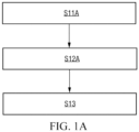
- FIG. 1A illustrates an exemplary flowchart of a workflow constructing and monitoring method according to embodiments of this application.
- the method may include the following steps:
- step S11A a behavior tree construction operation performed by a user on a graphical user interface on the basis of a preset behavior tree node is received.
- a behavior tree is configured to characterize a workflow that defines operations to be performed by a workcell. For example, it may represent distributed processes in the workcell.
- the workflow here may be further divided into a main workflow and subworkflows.
- the main workflow is used for limiting the start, the end, and other flow controls that trigger the entire workcell process.
- the main workflow is the entrance to the entire process, which is linked to at least one subworkflow.
- the subworkflows are usually major workflows. Each subworkflow corresponds to a subprocess and used for implementing a specific service operation.
- a workcell may be a combination of resources such as systems or devices that can implement a relatively complete and independent control process and operation.
- constructing a workflow by using a workcell as a basic unit is more in line with the characteristics of industrial control, which can improve the integration of development, and reduce the complexity of development.
- workcells may be defined according to actual industrial scenarios. For example, it may be defined that a process corresponds to a workcell, or a workstation in a process may be defined as a workcell, or it may be defined that a work position in a workstation corresponds to a workcell. Process flows of different workcells are different.
- the behavior tree nodes may include flow control nodes and function block nodes. They will be respectively described below in detail.
- Flow control nodes are configured to implement logic controls in workflows, typically independent of specific service operations in workcells. Through the flow control nodes, users can construct various workflows according to their own needs.
- the flow control nodes may include main control nodes, logic control nodes and condition nodes.
- the flow control nodes may include one or any combination of main control nodes, logic control nodes and condition nodes. They will be respectively described below in brief.
- the main control nodes may include some or all of a start node, an end node, a goto node, an anchor node, a stop node and an abort node.
- the main control nodes in this embodiment are not standard behavior tree elements, but in this embodiment, they can be configured to control the main processes of the workflow, and can be linked to a state machine of the workflow.
- the start node is mandatory.
- one of the end node or the goto node may also be mandatory.
- the main control nodes are mainly configured to define the start and end of the workflow.
- other element nodes can control the state machine (such as abort and stop) or annotate key process steps to skip to (such as key nodes).
- the logic control nodes may include some or all of a sequence (Se) node, a reactive sequence (RSe) node, a parallel (Pa) node, an in-process QC (IPQ) node, a priority (Pr (fallback)) node, a reactive priority (RPr (fallback)) node, an if-then-else (ITE) node and a switch (Sw) node.
- the logic control nodes can define how to execute branches in the behavior tree, and are configured to implement branch logic control in the workflow, etc. Each node will be described below in brief:
- sequence node and parallel node can drive most of the logics in the workflow.
- Condition nodes are usually the basic logical elements in the behavior tree that check expressions, and are configured to perform conditional judgments and return judgment results. It returns OK or FAILED on the basis of whether the conditions are met. The condition nodes never return the running state.
- condition nodes may be included within the function block nodes.
- condition nodes may be treated as a separate type of nodes.
- Function block nodes are configured to execute commands and implement service operations in the workflow. Normally, if the operation is completed correctly, it returns OK; and if the operation fails, it returns FAILED. If the operation is in progress, it returns running.
- the function block nodes include logic nodes, and may also include some or all of some specific types of function block nodes, such as manual nodes, dynamic nodes, delay nodes and empty (idle) nodes.
- the dynamic nodes are configured to dynamically inject node instances at a runtime.
- the manual nodes represent that a manual step stops at a current node before obtaining a confirmation signal and exits after obtaining the confirmation signal.
- the delay nodes represent that it exits a current node after delay of specific time.
- the empty (idle) nodes represent that no operation is performed and a placeholder can be replaced by any function block node.
- Each logic node may correspond to an operation template, and each operation template pre-defines operations that can be performed by at least one type of resources (such as cooperative robots or PLC devices). For example, the operations may include actions, methods or skills.
- each operation template may be composed of an interface part and an implementation part.
- the implementation part may be an application program (such as a containerized application program), which includes function codes and running dependencies. This application program can run independently, and is publicly available through a specific network communication interface.
- the interface part may be a logic node presented in graphical elements, which, like other behavior tree nodes, can be dragged, connected, and configured in the graphical user interface.
- each logic node may have a parameter panel for configuring the parameters of the logic node, such as input and output parameters. Of course, these input and output parameters may also be preset with default values.
- Each logic node may be configured and executed separately.
- execution of a logic node in the behavior tree an input configured by the user for the logic node will be read and transmitted to the implementation part of the operation template, that is, the corresponding application program.
- an operation result such as the transformed model will be transformed back into an output of the logical node.
- the interface part and implementation part of each operation template may be stored separately.
- the node library may only store the interface part, that is, the logic nodes, and the implementation part may be stored in a node service module, which may be referred to as a runtime in this embodiment.
- the node service module may be located on a server or locally.
- the above logic nodes follow the information model of runtime interaction with the main controller.
- standardization of communication between OT domain workflows and the main controllers of various OT devices is achieved.
- resources usually refer to resources that can execute workflows on site as operating subjects.
- the resources that serve as the execution subjects of the operations can be used as a common configuration parameter of a function block node for the corresponding resource configurations of the required function block nodes in construction of the behavior tree.
- the resources that serve as the execution subjects of the operations may be configured for the function block nodes, so that in construction of the behavior tree, there is no need to configure resources for the required function block nodes.
- FIG. 1B illustrates an exemplary diagram of a resource knowledge map in an example.
- this resource knowledge map is a factory resource knowledge map that describes the actual system configuration of a factory.
- the factory (F) node has an industrial personal computer (IPC) node.
- the industrial personal computer (IPC) node has a cooperative robot (CR) node, a PLC node, and a bar code scanner (BCS) node.
- IPC industrial personal computer
- CR cooperative robot
- PLC PLC node
- BCS bar code scanner
- the cooperative robot (CR) node has a clamping jaw (CJ) node, a torque wrench (TW) node, and a camera (CA) node.
- the PLC node has a button (B) node and an LED alarm lamp node.
- the various devices of this type may be distinguished by their numbers or models and the like, which will not be repeated here.
- Each function block node may be instantiated into an operation corresponding to a resource by associating the function block node with a resource node. For example, a certain logic node may be instantiated into an operation corresponding to a device by associating it with a device resource node.
- a resource header may be set for the function block node, and the resource associated with the function block node will be displayed in the resource header.
- each resource node may be pre-associated with a corresponding function block node, so that in construction of a behavior tree, the function block node associated with the corresponding resource can be directly pulled without the need for temporary configuration.
- FIG. 1C illustrates an exemplary diagram of each resource node associated with a function block node in an example. As shown in FIG. 1C , aiming at the resources shown in the resource knowledge map in FIG. 1B , corresponding function block nodes are respectively associated.
- the industrial personal computer (IPC) node is associated with a press button (PB) node and a display dialog box on screen (DDB) node.
- PB press button
- DDB display dialog box on screen
- the cooperative robot (CR) node is associated with a linear move (LM) node and a shutdown mobile (SM) node.
- the PLC node is associated with a read I/O (RIO) node and a write I/O (WIO) node.
- the bar code scanner (BCS) node is associated with a scan bar code (SBC) node.
- the clamping jaw (CJ) node is associated with an open (O) node and a grab (Gr) node.
- the torque wrench (TW) node is associated with a twist (T) node.
- the camera (CA) node is associated with a register (R) node, a calibration (Cb) node, a take photo (TP) node, and an object recognition (OR) node.
- the button (B) node is associated with a press button (PB,) node.
- the LED alarm lamp node is associated with a switch on (SO) node and a switch off (SF) node
- no resource node is pre-associated with the function block node, but a corresponding resource node is associated with the required function block node in construction of a behavior tree.
- function block nodes referred to as dedicated function block nodes
- function block nodes referred to as general function block nodes
- general function block nodes may be employed for simulation in advance. After it is determined that the robot has feasibility, it is to be purchased.
- this embodiment may further include the following decorator nodes.
- Decorator nodes are mainly configured to decorate function block nodes driven by logic control nodes. For example, they can be configured to determine whether branches or even individual nodes in the behavior tree can be executed.
- the decorator nodes may include some or all of a repeat (Rp) node, a retry (Rt) node, a one-shot (OS) node, a timeout (TO) node, a timer (Tm) node, an inverter (Iv) node, a force run (FR) node, a force OK (FO) node, a force failed (FF) node, and a guard (G) node.
- Rp repeat
- Rt retry
- OS timeout
- Tm timer
- Iv inverter
- FR force run
- F force OK
- FF force failed
- G guard
- the decorator nodes may also be included within the flow control nodes. That is, the flow control nodes may include some or all of main control nodes, logic control nodes and decorator nodes.
- each behavior tree node may be listed in the form of an icon on the graphical user interface.
- the user may determine the nodes required to construct the workflow by selecting and dragging the icons to add to the canvas.
- the nodes may also be configured with necessary parameters, such as resource allocation and/or input/output parameters.
- the behavior tree corresponding to the workflow may include multiple function block nodes. According to the sequence of and mutual relationship between the operations, corresponding flow control nodes may be set, and the behavior tree corresponding to the workflow may be finally generated by performing corresponding arrangement and connection on the dragged nodes. That is, the behavior tree construction operation includes the operations of adding and connecting behavior tree nodes. Further, it may also include the operation of associating resources with the added function block nodes. In addition, it may further include the operation of configuring the input/output parameters for the behavior tree nodes.
- step S12A a behavior tree corresponding to a workflow is generated in response to the behavior tree construction operation. Some or all of the function block nodes in the behavior tree are associated with resources that execute corresponding service operations.
- each behavior tree node may be instantiated in response to the behavior tree construction operation, and the connection relationships between the instantiated behavior tree nodes may be established.
- Some or all of the instantiated function block nodes are associated with resources that execute corresponding service operations. By performing this step, the added function block nodes can be instantiated into operations corresponding to resources. Then, on the basis of the connection relationships between the instantiated behavior tree nodes, a behavior tree corresponding to a workflow is generated.
- the above behavior tree nodes may be stored in a node library.
- the constructed behavior tree (or uninitialized behavior tree framework) corresponding to the workflow or subworkflow that preferably has been debugged or successfully run by the user is stored as a workflow node or subworkflow node.
- the node library may further include workflow (WF) nodes and subworkflow (SWF) nodes.
- WF workflow
- SWF subworkflow
- FIG. 2A illustrates a schematic diagram of a behavior tree of quality inspection production line workcells constructed in an example.
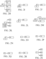
- FIG. 2B to FIG. 2S respectively illustrate schematic diagrams of partial behavior trees constructed in an example. The direction of the arrow indicates the execution sequence of the corresponding nodes.
- the function block nodes may be understood as presented in the form of a labeled diagram, and the construction of this behavior tree on the basis of the function block labeled diagram requires the participation of flow control nodes and even decorator nodes.
- the embodiments of the present disclosure further provide a behavior tree constructing method on the basis of a function block typed diagram, in which the function block nodes are presented in the form of a typed diagram. In practical applications, these two behavior tree constructing methods may coexist, and when one method is employed for constructing the behavior tree, the other method is also employed for synchronous construction.
- FIG. 1D illustrates an exemplary flowchart of another workflow constructing and monitoring method according to embodiments of this application.
- the method may include the following steps:
- step S11B a behavior tree construction operation performed by a user on a graphical user interface is received.
- the behavior tree construction operation includes operations of adding and connecting function block nodes on the basis of a function block typed diagram.
- the typed diagram and labeled diagram can be understood as two presentation methods of the same function block node, both of which are used for implementing a corresponding service operation.
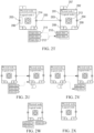
- FIG. 2T illustrates an example of constructing a behavior tree on the basis of function block nodes of a function block typed diagram.
- the function block typed diagram may include:
- a sensitive area 206 within the set range of the link input port 203 referred to as a first sensitive area here, which is configured to locate a connection endpoint on the link input port 203 when click and connection operations of the user are received within the first sensitive area.
- a sensitive area within the set range of the link output port 204, referred to as a second sensitive area here, which is configured to locate a connection endpoint on the link output port 204 when click and connection operations of the user are received within the second sensitive area.
- an instruction label 207 indicating the execution sequence of the function block nodes may be further generated for the function block nodes F1 and F2 connected with each other, and the instruction label 207 may be marked on the function block typed diagram of the function block nodes F1 and F2, such as 1 and 2 as shown.
- the instruction label 205 may also be used as an index for skip instructions and as a chapter index for instructional documents.
- the number of the data input ports of the function block nodes may be marked on the input dataset block 208, such as 5 on the input dataset block 208 of the function block node F1 and 2 on the input dataset block 208 of the function block node F2. If the number of the data input ports is zero, the input dataset block 208 may be hidden.
- the number of the data output ports of the function block nodes may be marked on the output dataset block 209, such as 3 on the output dataset block 209 of the function block node F1 and 1 on the output dataset block 209 of the function block node F2. If the number of the data output ports is zero, the output dataset block 209 may be hidden.
- each data input port of the function block nodes may be expanded or hidden by clicking on the input dataset block 208.
- Each data output port of the function block nodes may be expanded or hidden by clicking on the output dataset block 209.
- FIG. 2U illustrates a schematic diagram of hiding the data input port of the logic node 2 by clicking.
- FIG. 2V illustrates a schematic diagram of hiding the data output port of the logic node 1 by clicking.
- FIG. 2W illustrates a schematic diagram of simultaneously displaying each data input port and each data output port.
- FIG. 2X illustrates a schematic diagram of simultaneously hiding each data input port and each data output port.
- connection operation of the function block nodes may further include a connection operation between the data output port 211 and the data input port 210 between the corresponding data of the two function block nodes F1 and F2.
- a data connection 212 is established between the two function block nodes F1 and F2.
- the data connection 212 is used for indicating data transmission between the two function block nodes F1 and F2. As shown in FIG.
- a data connection 212 is established between the data output port 211 of the output data 1 of the function block node F1 and the data input port 210 of the input data 2 of the function block node F2, indicating that the output data 1 of the function block node F1 serves as the input data 2 of the function block node F2.
- a sensitive area within the set range of the data input port 210, referred to as a third sensitive area here, which is configured to locate a connection endpoint on the data input port 210 when click and connection operations of the user are received within the third sensitive area.
- a sensitive area within the set range of the data output port 211, referred to as a fourth sensitive area here, which is configured to locate a connection endpoint on the data output port 211 when click and connection operations of the user are received within the fourth sensitive area.
- the function block icon 213 may be a vector icon 213, which is used for visually representing the service operations of the function block node.
- the function block icon 213 may also be omitted.
- the addition operation of the function block nodes may include a dragging operation of the function block main body 214.
- step S12B a behavior tree corresponding to a workflow is constructed in response to the behavior tree construction operation, such as the addition and connection operation of the function block nodes on the basis of the form of a typed diagram.
- a behavior tree including flow control nodes and function block nodes on the basis of a function block labeled diagram in S 12A may be synchronously constructed.
- a behavior tree on the basis of the function block typed diagram in S 12B may also be synchronously constructed.
- these two behavior tree construction interfaces may be switched according to the selection of the user.
- the behavior tree on the basis of the function block typed diagram or the behavior tree on the basis of the function block labeled diagram may be switched to display according to the user's click operation on the behavior tree on the basis of the function block typed diagram or the behavior tree on the basis of the function block labeled diagram.
- At least one data block can be further added and connected for each function block node of at least one function block node in the behavior tree.
- Each data block is configured to present corresponding data in the service operation of the function block node connected thereto.
- the type of the data block may include some or all of data pair, datasheet, image, video and chart.
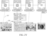
- FIG. 2Y illustrates a schematic diagram of respectively adding data blocks for four function block nodes in a behavior tree and displaying corresponding data in each data block in an example of this application.
- the function block node associated with a monitor for video recording is added with a data block of a type live data-video.
- the function block node associated with a torque wrench for screw tightening is added with a data block of a type live data-text and a data block of a type live data-chart.
- the function block node associated with a monitor for robot image acquisition is added with a data block of a type live data-image.
- the function block node associated with a camera for machine vision guide is added with a data block of a type live data-video.
- each data block may include a data block label 215 for indicating the type of the data block and a data block body 216 with a display area for presenting specific data.
- the data block label 215 may be a draggable label that can be moved to any position on the canvas, for example.
- the size of the display area of the data block body 216 is adjustable, which is configured to display different types of data from a data layer in real time.
- a monitoring link 217 is established between each data block and its corresponding function block node, and one function block may be mapped to multiple data blocks. When the workflow is executed, for example, in a runtime, the monitoring and output data corresponding to the function block node will be transmitted to the corresponding data block for live display.
- the data block is a low code data block, which differs from other SCADA and dashboard systems in that the low code data block in this embodiment is also a low code element, which can be used as a part of the behavior tree and whose attributes can be all managed in a low code logic.
- a data source in the low code data block comes from the data layer, which can obtain data through an interface provided by the data layer in a runtime or a cloud execution engine.
- the data source may be a time series database, an RDBMS, or a NoSQL.
- the low code data block is a flexible, scalable and adaptable system that can be applied to any function block node that can be associated with a physical device.
- the data block for achieving data monitoring can be considered as a visual interface of the data layer.
- this embodiment may further include the following step S13.
- step S13 the behavior tree is parsed, and the workflow corresponding to the behavior tree is deployed to a runtime of a corresponding workcell so that the runtime executes the workflow to control each resource in the workcell to execute the service operation according to the workflow.
- the corresponding data obtained in an execution process of the service operation may be further provided by the runtime to the corresponding data block for display.
- the runtime can directly provide the corresponding data obtained in the execution process of the service operation to the corresponding data block for display, or provide it to the corresponding data block through a third-party device for display.
- the workcell may have a main controller.
- the runtime may be located on the main controller of the workcell.
- device resources of the resources may be connected to the main controller, which controls the connected device resources connected thereto to execute corresponding service operations according to the workflow of the runtime.
- Human resources and other resources of the resources may directly execute corresponding operations according to workflow prompts of the runtime.
- the behavior tree may be stored in a markup language such as XML (extensible markup language) and may be validated by an XML Schema (XSD) prototype to verify whether the XML format of the behavior tree is correct.
- XML extensible markup language
- XSD XML Schema
- the OT domain typically refers to operational technology (OT), which combines hardware and software to detect or trigger changes in processes or events occurring within an enterprise by directly monitoring and/or controlling physical devices (referred to as OT devices).
- OT utilizes computers to monitor or change the physical state of an industrial control system (ICS).
- ICS industrial control system
- the industrial control system is configured to remotely monitor and/or control critical industrial processes on the basis of facilities, systems and devices implemented by computers, thus achieving physical functions.
- the term "OT” is used for distinguishing the industrial control system from traditional information technology (IT) systems in terms of technical implementation and functionality.
- Some tools are designed for use scenarios of the internet of things, targeting experienced IT engineers, while OT engineers and junior IT engineers find it difficult to understand their paradigms. However, some tools are more suitable for low code development scenarios in the IT domain, and may not be well suited for the OT domain.
- the above workflow constructing and monitoring method can be used for this OT domain as a low code development method for the OT domain.
- the workflow constructing and monitoring method shown in FIG. 1A may be implemented on the OT domain, such as an OT domain low code development platform.
- the workflow may be an OT domain workflow.
- the workcell may a workcell in the OT domain.
- the device may be an OT device.
- the OT device may include but is not limited to internet of things (IoT) devices, programmable logic controllers (PLCs), robotics, manual processes and industrial personal computers (IPCs).
- the above workflow constructing and monitoring method can be used for this ITOT system as an OT domain (which can be fused with the IT domain) low code development method.
- the workflow constructing and monitoring method shown in FIG. 1A may be implemented on the OT domain, such as an OT domain low code development platform.
- the workflow may be an OT domain workflow.
- the workcell may be a workcell in the OT domain.
- the IT device in order to achieve the fusion of the IT domain and the OT domain, on the basis of the workflow constructing and monitoring method shown in FIG. 1A , it further includes generating a microservice on the basis of the behavior tree, so that an IT device triggers the runtime of the main controller of the workcell to execute the OT domain workflow by calling the microservice.
- the IT device can call the microservice directly or through a knowledge middle platform.
- the runtime can provide the corresponding data obtained in the execution process of the service operation to the corresponding data block for display through the microservice.
- the runtime can provide the corresponding data obtained in the execution process of the service operation to a knowledge middle platform, and the knowledge middle platform performs processing including filtering on the data, and then provides the data to the corresponding data block for display directly or through the microservice.
- an API for the microservice may be generated on the basis of the behavior tree.
- the processing process in the API includes various operations in the OT domain workflow.
- the input parameters of the API are obtained from the input port of the OT domain workflow, and the output parameters of the API are obtained from the output port of the OT domain workflow.
- Method I the code developer of the OT domain may notify the code developer of the IT domain of the names and IP addresses of the generated microservices. In this way, the code developer of the IT domain can directly write the information of each microservice into the code in the development process, thus enabling the IT devices to call the microservice.
- Method I is more suitable for scenarios with a small number of microservices.
- Method II registration and discovery mechanisms may be employed. That is, the various microservices are registered on the knowledge middle platform, so that an IT domain code development tool achieves the effect that the IT device discovers the connected microservices through the knowledge middle platform.
- an IT domain code development tool may be used for achieving the effect that the IT domain device discovers the connected microservices through the knowledge middle platform through code development.
- the device that completes the microservice registration may be an OT domain microservice generator or a third-party device.
- the third-party device may be considered as part of the OT domain low code development platform, or may be implemented in the knowledge middle platform.
- the IT device may include but is not limited to manufacturing operation management (MOM) systems, manufacturing execution systems (MESs), enterprise resource planning (ERP)systems, enterprise service buses (ERPs) and product lifecycle management (PLM)systems.
- MOM manufacturing operation management
- MESs manufacturing execution systems
- ERP enterprise resource planning
- ERPs enterprise service buses
- PLM product lifecycle management
- the IT domain code development tool can achieve the effect that the IT device calls the microservices through a knowledge middle platform to trigger the runtime of the main controller of the workcell to execute the OT domain workflow through programming, thus achieving the control of the OT domain process by the IT domain code development platform, that is, achieving the fusion of the IT domain and the OT domain.
- the microservices are automatically generated by the OT domain microservice generator on the basis of the OT domain behavior tree, which does not require the IT domain code development tool to understand the details of the OT domain workflow but obtain the identifications (such as names) of the microservices and IP addresses, and does not require the development personnel of the IT domain to know the OT domain device and the control process, so that it is easy to implement and understand.
- the applicable fields of the embodiments of this application include but are not limited to industrial automation, logistics, laboratory, maritime, smart grid, electric vehicle infrastructure, electric vehicles, building automation, smart city, water treatment, garbage recycling and smart farm.
- FIG 3 illustrates a schematic structural diagram of a workflow constructing and monitoring system according to embodiments of this application.
- the system may include a node library 110, a graphical interface module 120 and an edit processing module 130.
- the node library 110 is configured with behavior tree nodes for constructing behavior trees.
- the behavior tree nodes include flow control nodes and function block nodes.
- a behavior tree is configured to characterize a workflow that defines operations to be performed by a workcell.
- the flow control nodes are configured to implement logic controls in workflows.
- the function block nodes are configured to implement service operations in the workflows.
- the function block nodes may include logic nodes. Each logic node corresponds to an operation template. Each operation template pre-defines operations that can be performed by at least one type of resources such as devices.
- the operations may include actions, methods or skills.
- the node library 110 may further include various types of data blocks. Each data block is configured to present corresponding data in the service operation of the function block node connected thereto.
- the type of the data block includes some or all of data types such as data pair, datasheet, image, video and chart.
- the resources are represented in the form of resource nodes, and all resource nodes are associated and stored in the form of a resource knowledge map.
- the resource knowledge map includes resource nodes and connection representing relationships between resource nodes.
- it may further include a resource library 150 for storing various resources in the form of the resource knowledge map.
- Each resource can execute at least one service operation.
- the flow control nodes may include some or all of main control nodes, logic control nodes and condition nodes.
- the main control nodes may include some or all of a start node, an end node, a goto node, an anchor node, a stop node and an abort node.
- the logic control nodes include some or all of a sequence node, a reactive sequence node, a parallel node, an in-process QC node, a priority node, a reactive priority node, an if-then-else node and a switch node.
- the function block nodes may further include some or all of manual nodes, dynamic nodes, delay nodes and empty nodes.
- the behavior tree nodes further include decorator nodes, which may include some or all of a repeat node, a retry node, a one-shot node, a timeout node, a timer node, an inverter node, a force run node, a force OK node, a force failed node, and a guard node.
- decorator nodes may include some or all of a repeat node, a retry node, a one-shot node, a timeout node, a timer node, an inverter node, a force run node, a force OK node, a force failed node, and a guard node.
- some or all of the function block nodes in the node library 110 are respectively bound to resources that execute service operations corresponding to the function block nodes.
- the function block nodes in the node library 110 may be presented in the form of a labeled diagram as shown in FIG. 2A to FIG. 2T , or in the form of a typed diagram as shown in FIG. 2T to FIG. 2X .
- the function block nodes in the node library 110 may also be presented only in the form of a typed diagram. For the specific structures of the function block nodes in the form of a function block typed diagram, see FIG. 2T , which will not be repeated here.
- the graphical interface module 120 is configured to provide a user a graphical user interface (GUI) for performing a behavior tree construction operation on the basis of the behavior tree nodes in the node library 110.
- GUI graphical user interface
- the graphical user interface (GUI) may also allow for addition and connection operations of data blocks.
- the graphical user interface may include a first graphical user interface for constructing a behavior tree on the basis of the flow control nodes and the function block nodes in the form of a function block labeled diagram, and a second graphical user interface for constructing a behavior tree on the basis of the function block nodes in the form of a function block typed diagram.
- the two graphical user interfaces may be switched to display according to the selection of the user.
- the behavior tree construction operation includes the addition and connection operations of the function block nodes.
- the addition operation of the function block nodes may include a dragging operation of the function block main body.
- the connection operation of the function block nodes may include a connection operation between the link output port and the link input port between the two function block nodes, and a connection operation between the data output port and the data input port between the corresponding data of the two function block nodes.
- Each behavior tree node may be listed in the form of an icon on the graphical user interface (GUI).
- GUI graphical user interface
- the edit processing module 130 is configured to construct a behavior tree corresponding to a workflow in response to the behavior tree construction operation.
- the edit processing module 130 is further configured to add and connect at least one data block to each function block node of at least one function block node in the behavior tree in response to the data block addition and connection operations.
- the edit processing module 130 may instantiate each behavior tree node in response to the behavior tree construction operation, and establish connection relationships between the instantiated behavior tree nodes. On the basis of the connection relationships between the instantiated behavior tree nodes, a behavior tree corresponding to a workflow is generated.
- Some or all of the instantiated function block nodes are associated with resources that execute corresponding service operations. For example, a logic node may be instantiated into an operation corresponding to a resource (such as a device).
- each behavior tree node and each data block may be listed in the form of icons on the graphical user interface.
- the user may determine the nodes required to construct the workflow by selecting and dragging the icons to add to the canvas.
- the nodes may also be configured with necessary parameters, such as resource allocation and/or input/output parameters.
- the behavior tree corresponding to the workflow may include multiple logic nodes. According to the sequence of and mutual relationship between the operations, the execution sequence of the logic nodes is determined, and the behavior tree corresponding to the workflow is finally generated by performing corresponding arrangement and connection on the dragged nodes.
- the behavior tree construction operation may further include the operation of associating resources with the added function block nodes.
- the workflow constructing and monitoring system in this embodiment may further include a parsing and deployment module 140 configured to parse the behavior tree, and deploy the workflow corresponding to the behavior tree to a runtime of a corresponding workcell so that the runtime executes the workflow to control each resource in the workcell to execute the service operation according to the workflow. Further, it may provide the corresponding data obtained in the execution process of the service operation to the corresponding data block for display.
- the workcell may have a main controller. In this case, the runtime may be located on the main controller of the workcell.
- device resources of the resources may be connected to the main controller, which controls the device resources connected thereto to execute corresponding operations according to the workflow of the runtime.
- Human resources and other resources of the resources may directly execute corresponding operations according to workflow prompts of the runtime.
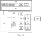
- FIG. 4A illustrates an OT domain low code development platform 100 provided according to embodiments of this application.
- the platform 100 can be configured to implement the workflow constructing and monitoring system shown in FIG. 3 .
- the OT domain low code development platform 100 may include: an OT domain low code development tool 10.
- the OT domain low code development tool 10 may be configured to implement the graphical interface module 120 and edit processing module 130 in the workflow constructing and monitoring system shown in FIG. 3 . Further, it can also implement the parsing and deployment module 140 in the workflow constructing and monitoring system shown in FIG. 3 .
- the node library 110 and the resource library 150 in the workflow constructing and monitoring system shown in FIG. 3 may be stored on a memory.
- the OT domain low code development platform 100 may further include a runtime 30 of the workcell.
- the OT domain low code development tool 10 may deploy the OT domain workflow corresponding to the generated behavior tree to the runtime 30 of the workcell so that the runtime 30 executes the workflow to control each OT resource such as an OT device in the workcell to execute the operation according to the OT domain workflow.
- the components of the OT domain low code development platform 100 shown in FIG. 4A and FIG. 4B only involve the OT domain. However, the fusion of the IT domain and the OT domain has become increasingly important for enterprise digital transformation. What needs to be achieved is how enterprises can adopt an easy-to-understand and non-IT-programming approach to control the process of the OT domain.
- the OT domain low code development platform 100 shown in FIG. 4C solves how to control the process of the OT domain through an IT domain code development platform 300.
- the OT domain low code development platform 100 may further include an OT domain microservice generator 20, which can generate microservices 40 on the basis of the OT domain behavior tree.
- the IT domain code development tool 301 can achieve the effect that the IT device calls the microservices 40 through a knowledge middle platform 200 to trigger the runtime 30 of the main controller of the workcell to execute the OT domain workflow through programming, thus achieving the control of the OT domain process by the IT domain code development platform 300, that is, achieving the fusion of the IT domain and the OT domain.
- the microservices 40 are automatically generated by the OT domain microservice generator 20 on the basis of the OT domain behavior tree, which does not require the IT domain code development tool 301 to understand the details of the OT domain workflow but obtain the identifications (such as names) of the microservices 40 and IP addresses, and does not require the development personnel of the IT domain to know the OT domain device and the control process, so that it is easy to implement and understand.
- the IT domains can obtain the information about the microservices 40.
- the implementation methods include but are not limited to the following two:
- Method I the code developer of the OT domain may notify the code developer of the IT domain of the names and IP addresses of the generated microservices 40. In this way, the code developer of the IT domain can directly write the information of each micro service 40 into the code in the development process, thus enabling the IT devices to call the microservices 40.
- Method I is more suitable for scenarios with a small number of microservices.
- Method II registration and discovery mechanisms may be employed.
- the various microservices 40 are registered on the knowledge middle platform 200, so that an IT domain code development tool 301 can achieve the effect that the IT domain device discovers the connected microservices 40 through the knowledge middle platform 200 through code development.
- the device that completes the microservice 40 registration may be an OT domain microservice generator 20 or a third-party device 50 shown in FIG. 4D .
- the third-party device 50 may be considered as part of the OT domain low code development platform 100, or may be implemented in the knowledge middle platform 200.
- Method II is more suitable for scenarios with a large number of microservices. By registering the microservices on the knowledge middle platform, the effect that the IT devices call the microservices can be more effectively achieved, and the fusion of the OT domain and the IT domain is strengthened.
- the OT domain microservice generator 20 may generate an API for the microservices 40 on the basis of the OT domain behavior tree.
- the processing process in the API includes various operations on each function block in the OT domain workflow.
- the input parameters of the API are obtained from the input port of the OT domain workflow, and the output parameters of the API are obtained from the output port of the OT domain workflow.
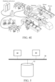
- FIG. 4E An application scenario of the OT domain low code development platform 100 provided in the embodiments of this application in the field of industrial automation is as shown in FIG. 4E .
- the low code development tool 10 generates a behavior tree corresponding to the OT domain workflow under the operation of the user. Further, each function block node of at least one function block node in the behavior tree may be added with at least one data block.
- the OT domain workflow defines the operations to be performed by the production line as a workcell shown on the right side of FIG. 4E .
- the corresponding workflow generated on the basis of the behavior tree is published to the runtime 30, so that the runtime 30 can control the completion of the operation of the production line of the workcell.
- monitoring data or output data in the operation process can be also obtained, and the obtained data can be provided to the data block of the graphical user interface of the low code development tool 10 for display.
- the corresponding microservices can be generated by the microservice generator 20 and registered in the knowledge middle platform 200, so that the IT domain code development tool 301 can call the corresponding microservices through the knowledge middle platform 200.
- the monitoring data or output data can be provided to the knowledge middle platform 200 for processing including filtering, and then directly provided to the corresponding data block for display by the knowledge middle platform 200, or provided to the corresponding data block for display by the knowledge middle platform 200 through the micro services.
- the user can edit the OT domain behavior tree by dragging and dropping various nodes, including function block nodes, as shown in the GUI at the lower left corner of FIG. 4E .
- required data such as workpiece machining parameters
- the workcell here is a production line, which includes machines, conveyor belts, robotic arms, personnel, PLC and AGB.
- the code development tool 301 in the IT domain may also be located on the same hardware device as the low code development tool 10, such as on the same computer.
- FIG 5 illustrates a schematic structural diagram of another workflow constructing and monitoring system according to embodiments of this application.
- the system can be configured to implement the method shown in FIG. 1A , implementing the workflow constructing and monitoring system shown in FIG. 3 , or implementing the workflow constructing and monitoring system shown in any one of FIG. 4A to FIG. 4D , namely the OT domain low code development platform 100.
- the aforementioned OT domain low code development tool 10, OT domain microservice generator 20, runtime 30, and third-party device 60 may all be implemented as separate hardware devices, such as servers, workstations, microcontrollers or processing chips.
- these devices may be implemented on the same hardware device and stored as software programs in at least one memory, to implement the aforementioned OT domain low code development method by calling through at least one processor.
- the node library 110, resource library 150, and generated microservices 40 may be stored in at least one memory.
- the system may include at least one memory 51, at least one processor 52, and at least one display 53.
- it may further include other components such as communication ports (not shown in FIG. 5 ). These components communicate through a bus 54.
- the at least one memory 51 is configured to store a computer program.
- the at least one memory 51 may include a computer-readable medium, such as a Random Access Memory (RAM).
- the at least one memory 51 may also store operating systems, etc.
- the operating systems include but are not limited to Android operating system, Symbian operating system, Windows operating system, Linux operating system, and so on.
- the above-mentioned computer storage program may include the following program modules: a node library 110, a graphical interface module 120, an edit processing module 130, a parsing and deployment module 140.
- it may further include an OT domain microservice generator 20, runtime 30, and a third-party device 50.
- the at least one processor 52 is configured to call the computer program stored in the at least one memory 51 to execute the workflow constructing and monitoring method described in the embodiments of this application.
- the at least one processor 52 may be a microprocessor, an application specific integrated circuit (ASIC), a digital signal processor (DSP), a central processing unit (CPU), a graphics processing unit (GPU), a state machine, or the like. It can receive and transmit data through the communication port.
- ASIC application specific integrated circuit
- DSP digital signal processor
- CPU central processing unit
- GPU graphics processing unit
- state machine or the like. It can receive and transmit data through the communication port.
- the at least one monitor 53 is configured to display a graphical user interface.
- the at least one processor 52 is configured to call the computer program stored in the at least one memory 51 to enable the system to execute the workflow constructing and monitoring method in any implementation described above.
- the communication interface is configured to achieve communication with other devices, such as communication with the knowledge middle platform 200.
- the OT domain low code development tool 10 for implementing the graphical interface module 120, the edit processing module 130 and the parsing and deployment module 140 may be a lightweight web-based application program that can be implemented on industrial sites (such as edge devices or local servers) or in the cloud (such as AWS public cloud or OpenStack private cloud). Its visual engineering paradigm originates from the function block typed diagram (FBTD).
- the OT domain microservice generator 20 can use modern translation programming languages to generate standard APIs such as RESTful or RPC.
- the runtime 30 can simply implement the OT domain workflow and provide openness on the basis of an open-source community ecosystem (such as Python).
- the runtime 30 may be deployed on an embedded IoT device such as Single Board Computer (SBC).
- SBC Single Board Computer
- the embodiments of this application may include devices with architectures different from those shown in FIG. 5 .
- the above architecture is only exemplary and is used for explaining the workflow constructing and monitoring method provided in the embodiments of this application.
- an ITOT domain fused system i.e., an ITOT system
- ITOT system may include an IT device and the workflow constructing and monitoring system in any implementation of this application.
- IT domain code development platform 300 shown in FIG. 4C and FIG. 4D .
- the embodiments of this application further provide a computer-readable storage medium.
- the computer-readable storage medium stores a computer-readable code.
- the computer-readable code when executed by a processor, causes the processor to perform the workflow constructing and monitoring method.
- the embodiments of this application further provide a computer program product.
- the computer program product is tangibly stored on a computer-readable medium and includes computer-readable instructions.
- the computer-readable instructions when executed, causes at least one processor to perform the steps of the workflow constructing and monitoring method in the embodiments of this application.
- a system or device with a storage medium may be provided.
- the computer-readable code implementing the functions of any implementation of the embodiments described above is stored on the storage medium.
- the computer (or CPU or MPU) of the system or device can read and execute the computer-readable code stored in the storage medium.
- some or all of the actual operations may be completed by the operating system on the computer through the instructions on the basis of the computer-readable code.
- the computer-readable code read from the storage medium may also be written to the memory set in the expansion board inserted into the computer or to the memory set in the expansion unit connected to the computer.
- examples of the computer-readable medium include but are not limited to floppy disks, CD ROMs, magnetic disks, optical disks (such as CD ROMs, CD-R, CD-RW, DVD-ROMs, DVD-RAMs, DVD-RW and DVD+RW), memory chips, ROMs, RAMs, ASICs, configured processors, all-optical media, all magnetic tapes or other magnetic media, or any other medium from which computer processors can read instructions.
- various other forms of computer-readable media may send or carry instructions to a computer, including routers, private or public networks, or other wired and wireless transmission devices or channels.
- computer-readable instructions may be downloaded from a server computer or cloud through a communication network.
- the instructions may include codes in any computer programming language, including C, C++, C language, Visual Basic, Java, and JavaScript.
Landscapes
- Engineering & Computer Science (AREA)
- Business, Economics & Management (AREA)
- Human Resources & Organizations (AREA)
- Theoretical Computer Science (AREA)
- Strategic Management (AREA)
- Entrepreneurship & Innovation (AREA)
- Economics (AREA)
- Physics & Mathematics (AREA)
- General Physics & Mathematics (AREA)
- Software Systems (AREA)
- Educational Administration (AREA)
- Development Economics (AREA)
- Game Theory and Decision Science (AREA)
- Marketing (AREA)
- Operations Research (AREA)
- Quality & Reliability (AREA)
- Tourism & Hospitality (AREA)
- General Business, Economics & Management (AREA)
- General Engineering & Computer Science (AREA)
- Management, Administration, Business Operations System, And Electronic Commerce (AREA)
Applications Claiming Priority (1)
| Application Number | Priority Date | Filing Date | Title |
|---|---|---|---|
| PCT/CN2022/075065 WO2023142066A1 (zh) | 2022-01-29 | 2022-01-29 | 工作流构建及监控方法、系统、介质及程序产品 |
Publications (2)
| Publication Number | Publication Date |
|---|---|
| EP4455956A1 true EP4455956A1 (de) | 2024-10-30 |
| EP4455956A4 EP4455956A4 (de) | 2025-10-15 |
Family
ID=87470203
Family Applications (1)
| Application Number | Title | Priority Date | Filing Date |
|---|---|---|---|
| EP22922896.0A Pending EP4455956A4 (de) | 2022-01-29 | 2022-01-29 | Arbeitsflusskonstruktion und überwachungsverfahren und -system sowie medium und programmprodukt |
Country Status (4)
| Country | Link |
|---|---|
| US (1) | US20250165891A1 (de) |
| EP (1) | EP4455956A4 (de) |
| CN (1) | CN118541708A (de) |
| WO (1) | WO2023142066A1 (de) |
Family Cites Families (24)
| Publication number | Priority date | Publication date | Assignee | Title |
|---|---|---|---|---|
| US20050091576A1 (en) * | 2003-10-24 | 2005-04-28 | Microsoft Corporation | Programming interface for a computer platform |
| AU2003100004A4 (en) * | 2003-01-06 | 2003-03-06 | Extrapoles Pty Limited | Automated creation of proprietary workflow systems |
| WO2008083489A1 (en) * | 2007-01-12 | 2008-07-17 | Hansjorg Baltes | Method and system for robot generation |
| US8312389B2 (en) * | 2007-08-31 | 2012-11-13 | Fair Isaac Corporation | Visualization of decision logic |
| US20110029441A1 (en) * | 2009-07-30 | 2011-02-03 | Gupta Pronob K | Method to generate workflow tasks directly from flowcharts for processing events in event-driven judicial case management systems with workflow control |
| US8825861B2 (en) * | 2011-06-26 | 2014-09-02 | International Business Machines Corporation | System management operational workflow templates |
| US20130124253A1 (en) * | 2011-11-15 | 2013-05-16 | Rockwell Automation Technologies, Inc. | Industry-specific workflows in a manufacturing execution system |
| US11397462B2 (en) * | 2012-09-28 | 2022-07-26 | Sri International | Real-time human-machine collaboration using big data driven augmented reality technologies |
| TWI475483B (zh) * | 2012-10-19 | 2015-03-01 | Taibotics Co Ltd | 自動裝置的程式開發方法 |
| US20140310053A1 (en) * | 2013-04-10 | 2014-10-16 | Xerox Corporation | Method and systems for providing business process suggestions and recommendations utilizing a business process modeler |
| WO2016014137A2 (en) * | 2014-05-06 | 2016-01-28 | Neurala, Inc. | Apparatuses, methods, and systems for defining hardware-agnostic brains for autonomous robots |
| WO2016145475A2 (en) * | 2015-03-13 | 2016-09-22 | Thepowertool Pty Ltd | System of standardized api interpretation for inter application communication |
| EP3394744A4 (de) * | 2015-12-22 | 2019-07-31 | Opera Solutions U.S.A., LLC | System und verfahren zur schnellen entwicklung und den schnellen einsatz eines wiederverwendbaren analysecodes zur verwendung in der computerisierten datenmodellierung und -analyse |
| US20200007615A1 (en) * | 2017-06-05 | 2020-01-02 | Umajin Inc. | Server kit configured to execute custom workflows and methods therefor |
| CN109933010B (zh) * | 2017-12-15 | 2023-11-10 | 中国科学院沈阳自动化研究所 | 一种面向个性化定制的工业cps系统和实现方法 |
| CN108762769B (zh) * | 2018-06-04 | 2022-06-21 | 万惠投资管理有限公司 | 微服务应用编排和部署方法、装置及计算机终端 |
| US11385954B2 (en) * | 2019-01-28 | 2022-07-12 | Yahoo Assets Llc | Graphical management of big data pipelines |
| EP3712787B1 (de) * | 2019-03-18 | 2021-12-29 | Siemens Aktiengesellschaft | Verfahren zum erzeugen einer semantischen beschreibung einer zusammengesetzten interaktion |
| US20210004711A1 (en) * | 2019-07-02 | 2021-01-07 | International Business Machines Corporation | Cognitive robotic process automation |
| EP3926422A1 (de) * | 2020-06-17 | 2021-12-22 | Siemens Aktiengesellschaft | Verfahren zur programmierung mindestens einer maschine in einem industriellen automatisierungssystem |
| US11756543B2 (en) * | 2020-10-27 | 2023-09-12 | Incentive Marketing Group, Inc. | Methods and systems for application integration and macrosystem aware integration |
| US11074107B1 (en) * | 2020-11-04 | 2021-07-27 | RazorThink, Inc. | Data processing system and method for managing AI solutions development lifecycle |
| US20220327006A1 (en) * | 2021-04-09 | 2022-10-13 | Nb Ventures, Inc. Dba Gep | Process orchestration in enterprise application of codeless platform |
| EP4083722B1 (de) * | 2021-04-30 | 2024-11-06 | Siemens Aktiengesellschaft | Verfahren zur automatischen erzeugung eines verhaltensbaumprogramms zur steuerung einer maschine |
-
2022
- 2022-01-29 US US18/832,501 patent/US20250165891A1/en active Pending
- 2022-01-29 WO PCT/CN2022/075065 patent/WO2023142066A1/zh not_active Ceased
- 2022-01-29 CN CN202280089254.8A patent/CN118541708A/zh active Pending
- 2022-01-29 EP EP22922896.0A patent/EP4455956A4/de active Pending
Also Published As
| Publication number | Publication date |
|---|---|
| US20250165891A1 (en) | 2025-05-22 |
| EP4455956A4 (de) | 2025-10-15 |
| CN118541708A (zh) | 2024-08-23 |
| WO2023142066A1 (zh) | 2023-08-03 |
Similar Documents
| Publication | Publication Date | Title |
|---|---|---|
| EP4459525A1 (de) | Verfahren und system zur arbeitsablauferzeugung sowie medium und programmprodukt | |
| CN101571802B (zh) | 一种嵌入式软件测试数据可视化自动生成方法及系统 | |
| WO2023164841A1 (zh) | 工作流执行方法、装置、存储介质及程序产品 | |
| WO2023004806A1 (zh) | Ai模型的设备部署方法、系统及存储介质 | |
| EP4459398A1 (de) | Arbeitsflusserzeugungsverfahren, -vorrichtung und -system, -medium und -programmprodukt | |
| Fend et al. | CPSAML: A language and code generation framework for digital twin based monitoring of mobile cyber-physical systems | |
| EP4455814A1 (de) | Arbeitsflusssteuerungsverfahren, -vorrichtung und -system sowie medium und programmprodukt | |
| US7640538B2 (en) | Virtual threads in business process programs | |
| EP4455869A1 (de) | Arbeitsflusskonstruktionsverfahren und -system, medium und programmprodukt | |
| EP4462299A1 (de) | Verfahren und system zur implementierung eines dynamischen arbeitsablaufs, medium und programmprodukt | |
| EP4455956A1 (de) | Arbeitsflusskonstruktion und überwachungsverfahren und -system sowie medium und programmprodukt | |
| WO2023142079A1 (zh) | 工作流创建方法、系统、介质及程序产品 | |
| EP4471687A1 (de) | Arbeitsflussausführungsverfahren und -system, medium und programmprodukt | |
| EP4459470A1 (de) | Arbeitsflusserzeugungsverfahren, -vorrichtung und -system, -medium und -programmprodukt | |
| EP4465614A1 (de) | Arbeitsflussausführungsverfahren und -vorrichtung, speichermedium und programmprodukt | |
| Cui et al. | A software architecture supporting self-adaptation of wireless control networks | |
| Yu et al. | The implementation of IEC60870-5-104 based on UML statechart and Qt state machine framework | |
| Trowitzsch | Quantitative Evaluation of UML State Machines Using Stochastic Petri Nets | |
| KR20250170498A (ko) | 비전-언어 에이전트를 이용한 자동화 시스템 및 방법 | |
| KR20250170497A (ko) | 비전-언어 에이전트를 이용한 자동화 시스템 및 방법 | |
| CN121501627A (zh) | 一种融合stpa方法的安全关键软件测试建模方法及装置 |
Legal Events
| Date | Code | Title | Description |
|---|---|---|---|
| STAA | Information on the status of an ep patent application or granted ep patent |
Free format text: STATUS: THE INTERNATIONAL PUBLICATION HAS BEEN MADE |
|
| PUAI | Public reference made under article 153(3) epc to a published international application that has entered the european phase |
Free format text: ORIGINAL CODE: 0009012 |
|
| STAA | Information on the status of an ep patent application or granted ep patent |
Free format text: STATUS: REQUEST FOR EXAMINATION WAS MADE |
|
| 17P | Request for examination filed |
Effective date: 20240726 |
|
| AK | Designated contracting states |
Kind code of ref document: A1 Designated state(s): AL AT BE BG CH CY CZ DE DK EE ES FI FR GB GR HR HU IE IS IT LI LT LU LV MC MK MT NL NO PL PT RO RS SE SI SK SM TR |
|
| DAV | Request for validation of the european patent (deleted) | ||
| DAX | Request for extension of the european patent (deleted) | ||
| REG | Reference to a national code |
Ref country code: DE Ref legal event code: R079 Free format text: PREVIOUS MAIN CLASS: G06Q0010060000 Ipc: G05B0019042000 |
|
| A4 | Supplementary search report drawn up and despatched |
Effective date: 20250915 |
|
| RIC1 | Information provided on ipc code assigned before grant |
Ipc: G05B 19/042 20060101AFI20250909BHEP Ipc: G06F 8/34 20180101ALI20250909BHEP Ipc: G06F 9/50 20060101ALI20250909BHEP Ipc: G06F 11/32 20060101ALI20250909BHEP Ipc: G06Q 10/0633 20230101ALI20250909BHEP Ipc: G06Q 10/06 20230101ALI20250909BHEP Ipc: G06F 9/445 20180101ALN20250909BHEP Ipc: G06F 8/36 20180101ALN20250909BHEP Ipc: G05B 19/05 20060101ALN20250909BHEP |