EP4455869A1 - Arbeitsflusskonstruktionsverfahren und -system, medium und programmprodukt - Google Patents
Arbeitsflusskonstruktionsverfahren und -system, medium und programmprodukt Download PDFInfo
- Publication number
- EP4455869A1 EP4455869A1 EP22922908.3A EP22922908A EP4455869A1 EP 4455869 A1 EP4455869 A1 EP 4455869A1 EP 22922908 A EP22922908 A EP 22922908A EP 4455869 A1 EP4455869 A1 EP 4455869A1
- Authority
- EP
- European Patent Office
- Prior art keywords
- function block
- workflow
- nodes
- data
- node
- Prior art date
- Legal status (The legal status is an assumption and is not a legal conclusion. Google has not performed a legal analysis and makes no representation as to the accuracy of the status listed.)
- Pending
Links
Images


Classifications
-
- G—PHYSICS
- G06—COMPUTING OR CALCULATING; COUNTING
- G06F—ELECTRIC DIGITAL DATA PROCESSING
- G06F9/00—Arrangements for program control, e.g. control units
- G06F9/06—Arrangements for program control, e.g. control units using stored programs, i.e. using an internal store of processing equipment to receive or retain programs
- G06F9/46—Multiprogramming arrangements
- G06F9/50—Allocation of resources, e.g. of the central processing unit [CPU]
- G06F9/5005—Allocation of resources, e.g. of the central processing unit [CPU] to service a request
- G06F9/5027—Allocation of resources, e.g. of the central processing unit [CPU] to service a request the resource being a machine, e.g. CPUs, Servers, Terminals
- G06F9/5038—Allocation of resources, e.g. of the central processing unit [CPU] to service a request the resource being a machine, e.g. CPUs, Servers, Terminals considering the execution order of a plurality of tasks, e.g. taking priority or time dependency constraints into consideration
-
- G—PHYSICS
- G05—CONTROLLING; REGULATING
- G05B—CONTROL OR REGULATING SYSTEMS IN GENERAL; FUNCTIONAL ELEMENTS OF SUCH SYSTEMS; MONITORING OR TESTING ARRANGEMENTS FOR SUCH SYSTEMS OR ELEMENTS
- G05B19/00—Program-control systems
- G05B19/02—Program-control systems electric
- G05B19/04—Program control other than numerical control, i.e. in sequence controllers or logic controllers
- G05B19/05—Programmable logic controllers, e.g. simulating logic interconnections of signals according to ladder diagrams or function charts
- G05B19/056—Programming the PLC
-
- G—PHYSICS
- G06—COMPUTING OR CALCULATING; COUNTING
- G06F—ELECTRIC DIGITAL DATA PROCESSING
- G06F3/00—Input arrangements for transferring data to be processed into a form capable of being handled by the computer; Output arrangements for transferring data from processing unit to output unit, e.g. interface arrangements
- G06F3/01—Input arrangements or combined input and output arrangements for interaction between user and computer
- G06F3/048—Interaction techniques based on graphical user interfaces [GUI]
- G06F3/0484—Interaction techniques based on graphical user interfaces [GUI] for the control of specific functions or operations, e.g. selecting or manipulating an object, an image or a displayed text element, setting a parameter value or selecting a range
- G06F3/0486—Drag-and-drop
-
- G—PHYSICS
- G06—COMPUTING OR CALCULATING; COUNTING
- G06F—ELECTRIC DIGITAL DATA PROCESSING
- G06F8/00—Arrangements for software engineering
- G06F8/30—Creation or generation of source code
- G06F8/34—Graphical or visual programming
-
- G—PHYSICS
- G06—COMPUTING OR CALCULATING; COUNTING
- G06F—ELECTRIC DIGITAL DATA PROCESSING
- G06F8/00—Arrangements for software engineering
- G06F8/40—Transformation of program code
- G06F8/41—Compilation
- G06F8/43—Checking; Contextual analysis
- G06F8/436—Semantic checking
- G06F8/437—Type checking
-
- G—PHYSICS
- G06—COMPUTING OR CALCULATING; COUNTING
- G06Q—INFORMATION AND COMMUNICATION TECHNOLOGY [ICT] SPECIALLY ADAPTED FOR ADMINISTRATIVE, COMMERCIAL, FINANCIAL, MANAGERIAL OR SUPERVISORY PURPOSES; SYSTEMS OR METHODS SPECIALLY ADAPTED FOR ADMINISTRATIVE, COMMERCIAL, FINANCIAL, MANAGERIAL OR SUPERVISORY PURPOSES, NOT OTHERWISE PROVIDED FOR
- G06Q10/00—Administration; Management
- G06Q10/06—Resources, workflows, human or project management; Enterprise or organisation planning; Enterprise or organisation modelling
- G06Q10/063—Operations research, analysis or management
- G06Q10/0633—Workflow analysis
-
- G—PHYSICS
- G06—COMPUTING OR CALCULATING; COUNTING
- G06Q—INFORMATION AND COMMUNICATION TECHNOLOGY [ICT] SPECIALLY ADAPTED FOR ADMINISTRATIVE, COMMERCIAL, FINANCIAL, MANAGERIAL OR SUPERVISORY PURPOSES; SYSTEMS OR METHODS SPECIALLY ADAPTED FOR ADMINISTRATIVE, COMMERCIAL, FINANCIAL, MANAGERIAL OR SUPERVISORY PURPOSES, NOT OTHERWISE PROVIDED FOR
- G06Q10/00—Administration; Management
- G06Q10/10—Office automation; Time management
- G06Q10/103—Workflow collaboration or project management
Definitions
- Embodiments of the present application relate to the field of industrial technologies, and in particular, to a workflow construction method and system, a computer-readable storage medium and a computer program product.
- a workflow can be simply defined as a description of a series of operation processes.
- the workflow is widely used in fields such as automated systems, artificial intelligence and robots.
- a workflow of a product sorting line in an automated system can be simply described as starting, taking photos, classifying, and moving products to target positions.
- a model deployment workflow in the field of artificial intelligence can be described as data collection, data annotation, model training, and model deployment.
- Embodiments of the present application provide a workflow construction method and system, a computer-readable storage medium and a computer program product to quickly and conveniently implement workflow creation.
- a workflow construction method which includes: receiving function block node addition and connection operations performed on a graphical user interface (GUI) by a user on the basis of function block type graphs, where each function block node correspondingly implements a service operation; each function block type graph includes: a function block name for indicating the type of a service operation, a function block header for indicating a resource for executing a service operation, a link input port and a link output port for triggering link connection, an input data chunk for representing a set of all data input ports and an output data chunk for representing a set of all data output ports, a data input port and a data output port for triggering data transmission, and a function block body for bearing each component; the function block node addition operation includes: a dragging operation for the function block body; the function block node connection operation includes: a line connection operation between the link output port and the link input port between two function block nodes, and a line connection operation between the data output port and the data input port between corresponding
- a workflow construction system which includes: a node library, in which function block nodes for constructing a behavior tree are arranged, where the function block nodes are presented in the form of a function block type graph on a GUI; each function block type graph includes: a function block name for indicating the type of a service operation, a function block header for indicating a resource for executing a service operation, a link input port and a link output port for triggering link connection, an input data chunk for representing a set of all data input ports and an output data chunk for representing a set of all data output ports, a data input port and a data output port for triggering data transmission, and a function block body for bearing each component; a graphical interface module, configured to provide a GUI for a user to perform function block node addition and connection operations, where the function block node addition operation includes: a dragging operation for the function block body; the function block node connection operation includes: a line connection operation between the link output port and the link input port between two
- another workflow construction system which includes: at least one memory, configured to store computer-readable codes; and at least one processor, configured to call the computer-readable codes to execute steps in the method provided in the first aspect.
- an IT domain and OT domain fusion system which includes an IT device and a workflow construction system as described in any one of the above implementations, where the workflow is an OT domain workflow; the workcell is a workcell in an OT domain; the resources are OT resources; and the workflow generation system further includes: an OT domain microservice generator, configured to generate a microservice based on the behavior tree so that the IT device triggers the runtime of the workcell to execute the OT domain workflow by calling the microservice.
- a computer-readable medium stores computer-readable instructions, and the computer-readable instructions, when executed by a processor, cause the processor to execute steps in the method provided in the first aspect.
- a computer program product is provided.
- the computer program product is tangibly stored on a computer-readable medium and includes computer-readable instructions, and the computer-readable instructions, when executed, cause at least one processor to execute steps in the method provided in the first aspect.
- the operations that can be executed by various types of corresponding resources are encapsulated into corresponding function block nodes, so that a behavior tree can be used for representing the operation processes of a workflow. Due to the reusability of nodes, decoupling of a specific service and an engineering platform is achieved. Moreover, organizing the nodes in the form of a behavior tree can generate intuitive workflow operation processes from development to implementation, thereby reducing the complexity of workflow construction and achieving quick and convenient workflow creation.
- the behavior tree is analyzed, and the OT domain workflow corresponding to the behavior tree is deployed to the runtime of the workcell so that the resources in the workcell execute the operations according to the workflow. In this way, the purpose of controlling the operations of the workcell based on the workflow is achieved.
- the workflow is an OT domain workflow; the workcell is a workcell in an OT domain; and the device is an OT device. In this way, the workflow creation in the OT domain is achieved.
- a microservice is generated based on the OT domain workflow so that the IT device in the IT domain triggers the runtime of a main controller of the workcell to execute the OT domain workflow by calling the microservice.
- the IT device can call the microservice generated based on the OT domain workflow, thereby triggering the execution of the OT workflow to achieve the fusion of the IT domain and the OT domain.
- the term “include” and variants thereof represent open terms, and mean “include but is not limited to”.
- the term “based on” represents “at least partially based on”.
- the terms “one embodiment” and “an embodiment” represent “at least one embodiment”.
- the term “another embodiment” represents “at least one another embodiment”.
- the terms “first”, “second”, and the like may represent different objects or the same object. Other definitions may be included explicitly or implicitly in the following. Unless otherwise clearly specified, the definition of one term is consistent in the entire specification.
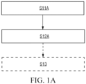
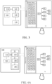
- FIG. 1A shows a schematic flowchart of a workflow construction method provided in an embodiment of the present application. As shown in FIG. 1A , the method may include the following steps: Step S11A: A behavior tree construction operation performed on a GUI by a user on the basis of preset behavior tree nodes is received.
- one behavior tree is used for representing one workflow, and the workflow is used for defining the operation to be executed by one workcell.
- the behavior tree may represent distributed processes in the workcell.
- the workflow here may be further divided into a main workflow and a subworkflow.
- the main workflow is used for limiting the start, end, and other flow controls that trigger the entire workcell process.
- the main workflow is an inlet of the entire process, which is linked to at least one subworkflow.
- Subworkflows are usually master workflows, and each subworkflow corresponds to a subprocess for implementing a specific service operation.
- the workcell may be a combination of resources such as systems or devices capable of implementing a relatively complete and independent control process and operation.
- workflow creation is performed based on the workcell as a basic unit, which more conforms to the characteristics of industrial control, can improve the integration level of development, and can reduce the complexity of development.
- the workcell may be defined according to actual industrial scenarios.
- a process may be defined as corresponding to a workcell, or a work station in a process may be defined as a workcell, or a work position in a work station may also be defined as corresponding to a workcell and the like, and different workcells have different process flows.
- the behavior tree nodes may include: flow control nodes and function block nodes. The details are respectively described below.
- the flow control nodes are used for implementing logical control in workflows, and are usually independent of specific service operations in the workcells. Through the flow control nodes, users can create various workflows according to their own needs.
- the flow control nodes may include: main control nodes, logical control nodes, condition nodes, and the like.
- the flow control nodes may also include: one or any combination of main control nodes, logical control nodes and condition nodes. The details are respectively described briefly below.
- the main control nodes may include: some or all of a start node, an end node, a goto node, an anchor node, a stop node and an abort node.
- the main control nodes in this embodiment are not standard behavior tree elements. However, in this embodiment, the main control nodes may be configured to control main processes of a workflow and may be linked to a state machine of the workflow.
- the start node is mandatory. In addition, one of the end node and the goto node may also be mandatory.
- the main control nodes are mainly used for defining the start and end of the workflow.
- other element nodes may control the state machine (such as abort and stop) or annotate critical process steps (such as anchor nodes) that may be skipped.
- the logical control nodes may include: some or all of a sequence (Se) node, a reactive sequence (RSe) node, a parallel (Pa) node, an in-process QC (IPQ) node, a priority (Pr) (fallback) node, a reactive priority (RPr) (fallback) node, an if-then-else (ITE) node, and a switch (Sw) node
- the logical control nodes can define how to execute branches in a behavior tree, and are configured to implement branch logical control in the workflow, and the like. Each of the nodes is described briefly below:
- the Se node and the Pa node may drive most of logics in a workflow.
- Condition nodes are usually basic logical elements in a behavior tree that check expressions, and are used for executing condition judgment and returning judgment results. Success or failure is returned according to whether the conditions are met. The condition node never returns a running state.
- condition nodes may also be included in function block nodes.
- condition nodes may also be separately used as a type of nodes.
- Function block nodes are used for executing commands and implementing service operations in workflows. In general, if the operation is completed correctly, success is returned; if the operation fails, failure is returned; and when the operation is in progress, running is returned.
- the function block nodes include logical nodes, and may also include some specific types of function block nodes, such as some or all of manual nodes, dynamic nodes, delay nodes, and empty (idle) nodes.
- the dynamic node is used for dynamically injecting a node instance at a runtime.
- the manual node represents a manual step that stops at the current node before obtaining a confirmation signal and exits after obtaining the confirmation signal.
- the delay node represents that the current node exits after a specified delay time.
- the empty (idle) node represents that no operation is executed, and is a placeholder which may be replaced with any function block node.
- Each logical node may correspond to one operation template, and each operation template defines at least one type of resources in advance, such as the operations that can be executed by (cooperative robot or PLC devices).
- the operations may include: actions, methods or skills.
- each operation template may be composed of an interface part and an implementation part.
- the implementation part may be an application (such as a containerized application) that includes function codes and runtime dependencies. This application may run independently and is publicly available through a specific network communication interface.
- the interface part may be logical nodes presented in graphical elements, which, like other behavior tree nodes, may be dragged, connected and configured in a GUI.
- each logical node may have a parameter panel for configuring parameters of the logical node, such as input and output parameters. Of course, these input and output parameters may also be preset with default values.
- Each logical node may be configured and executed separately.
- the input configured by a user for the logical node will be read and transmitted to the implementation part of the operation template, that is, the corresponding application.
- the operation result such as the converted model, will be converted back to the output of the logical node.
- the interface part and implementation part of each operation template may be stored separately.
- the node library may only store the interface part, namely the logical nodes, and the implementation part may be stored in a node service module.
- the node service module may be referred to as a runtime.
- the node service module may be located in a server or may also be located locally.
- the above logical nodes follow an information model interacting with the runtime of the main controller.
- standardization of communication between OT domain workflows and main controllers of various OT devices is implemented.
- the service operation corresponding to a function block node may be executed by different main bodies, such as a specific physical device, personnel or other virtualized resources, for the convenience of description, these physical devices, personnel and virtualized resources are collectively referred to as resources herein, and these resources usually refer to the resources that can execute workflows on site as various operation main bodies.
- the resource that serves as an operation execution body may be used as a common configuration parameter for a function block node, and corresponding resource configurations may be made for the required function block node when a behavior tree is created.
- the resource that serves as an operation execution body is configured for the function block node, so that when a behavior tree is created, there is no need to make resource configurations for the required function block node.
- these resources may also be represented in the form of resource nodes, and these resource nodes may be stored in the form of a resource knowledge graph.
- the resource knowledge graph includes: the resource nodes and connecting lines representing relationships among the resource nodes.
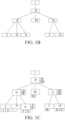
- FIG. 1B shows a schematic view of a resource knowledge graph in an example.
- the resource knowledge graph is a factory resource knowledge graph, which describes the real system configuration of a factory.
- F nodes have IPC nodes, and the IPC nodes have cooperative robot (CR) nodes, PLC nodes and bar code scanner (BCS) nodes, where the cooperative robot (CR) nodes have clamping jaw (CJ) nodes, torque wrench (TW) nodes and camera (CA) nodes; and the PLC nodes have button (B) nodes and LED alarm light nodes.
- CR cooperative robot
- CJ clamping jaw
- TW torque wrench
- CA camera
- B button (B) nodes and LED alarm light nodes.
- Each function block node may be associated with a resource node, so that the function block node may be instantiated as an operation of the corresponding resource.
- a logical node may be associated with a device resource node to be instantiated as an operation of the corresponding device.
- a header may be set for a function block node, and the resource associated with the function block node will be displayed in the header.
- each resource node may be associated with a corresponding function block node in advance, so that when a behavior tree is created, the function block node associated with the corresponding resource may be directly pulled without the need for temporary configuration.
- FIG. 1C shows a schematic view of associating each resource node with a function block node in an example. As shown in FIG. 1C , corresponding function block nodes are respectively associated with the resources shown in the resource knowledge graph in FIG. 1B .
- the IPC nodes are associated with press button (PB) nodes and display dialog box on screen (DDB) nodes;
- the cooperative robot (CR) nodes are associated with linear move (LM) nodes and shutdown mobile (SM) nodes;
- the PLC nodes are associated with read I/O (RIO) nodes and write I/O (WIO) nodes;
- the bar code scanner (BCS) nodes are associated with scan bar code (SBC) nodes;
- the clamping jaw (CJ) nodes are associated with open (O) nodes and grab (Gr) nodes;
- the torque wrench (TW) nodes are associated with twist (T) nodes;
- the camera (CA) nodes are associated with register (R) nodes, calibration (Cb) nodes, take photo (TP) nodes and object recognition (OR) nodes;
- the button (B) nodes are associated with press button (PB) nodes; and the LED alarm light nodes are associated with switch on (SO) nodes and switch off (SF) nodes.
- function block nodes may also not be associated with resource nodes in advance, and the required function block node is associated with the corresponding resource node when a behavior tree is created.
- function block nodes associated with resource nodes in advance referred to as dedicated function block nodes
- function block nodes not associated with resource nodes referred to as general function block nodes
- general function block nodes are not associated with on-site resources, it does not affect the analog simulation of the workflow corresponding to the behavior tree that includes the function block nodes. For example, if a cooperative robot is not purchased yet, in order to verify the feasibility, corresponding general function block nodes may be used for simulation in advance. When it is determined that it has feasibility, procurement may be initiated.
- this embodiment may further include the following decorator nodes:
- Decorator nodes are mainly used for decorating function block nodes driven by logical control nodes.
- Decorator nodes can be used for determining whether branches or even individual nodes in a behavior tree can be executed.
- Decorator nodes may include: some or all of a repeat (Rp) node, a retry (Rt) node, a one-shot (OS) node, a timeout (TO) node, a timer (Tm) node, an inverter (Iv) node, a force run (FR) node, a force OK (FO) node, a force failed (FF) node, and a guard (G) node.
- Rp repeat
- Rt retry
- OS timeout
- Tm timer
- Iv inverter
- FR force run
- F force OK
- FF force failed
- G guard
- decorator nodes may also be included in flow control nodes.
- the flow control nodes may include: all or some of main control nodes, logical control nodes and decorator nodes.
- each behavior tree node may be listed in the form of an icon on the GUI, and users can determine the nodes required for creating a workflow by selecting and dragging icons to be added to a canvas. Further, necessary parameter configuration, such as resource configuration and/or input and output parameter configuration, may also be performed on nodes. If one workcell needs to perform more than one operation defined in the required workflow, the behavior tree corresponding to the workflow may include multiple function block nodes, corresponding flow control nodes may be set according to the sequence and relationships of operations, and the dragged nodes are arranged and connected correspondingly to finally generate a behavior tree corresponding to the workflow. That is, the behavior tree construction operation includes behavior tree node addition and connection operations. Further, the behavior tree construction operation may include an operation of associating resources for the added function block nodes. In addition, the behavior tree construction operation may further include: a configuration operation for input and output parameters of behavior tree nodes.
- Step S12A A behavior tree corresponding to one workflow is generated in response to the behavior tree construction operation. Some or all of the function block nodes in the behavior tree may be associated with resources for executing corresponding service operations. In general, for workflows that need to be implemented by on-site resources, all function block nodes in the behavior tree need to be associated with resources for executing corresponding service operations; and for action flows that do not need to be implemented by on-site resources temporarily, such as workflows for analog simulation, it is not necessary for all function block nodes to be associated with resources for executing corresponding service operations. For example, if a cooperative robot is not purchased yet, in order to verify the feasibility, corresponding general function block nodes may be used for simulation in advance. When it is determined that it has feasibility, procurement may be initiated.
- the behavior tree nodes may be instantiated and connection relationships among the instantiated behavior tree nodes may be established in response to the behavior tree construction operation.
- Some or all of the instantiated function block nodes are associated with resources for executing corresponding service operations. By executing this step, the added function block node may be instantiated as an operation of the corresponding resource. Then, a behavior tree corresponding to one workflow is generated based on the connection relationships among the instantiated behavior tree nodes.
- the above behavior tree nodes may be stored in the node library.
- the behavior tree (or uninstantiated behavior tree framework) of the corresponding workflow or corresponding subworkflow that is constructed, preferably debugged or successfully executed by users is stored as a workflow node or a subworkflow node.
- the node library may further include workflow (WF) nodes and subworkflow (SWF) nodes.
- WF workflow
- SWF subworkflow
- FIG. 2A shows a schematic view of constructing a behavior tree for a workcell of a quality inspection production line in an example.
- FIG. 2B to FIG. 2S respectively show schematic views of a part of a behavior tree constructed in an example.
- the direction of an arrow represents an execution sequence of the corresponding nodes.
- the function block nodes may be understood as being presented in the form of a label graph, and the construction of the behavior tree based on the function block label graph requires the participation of flow control nodes and even decorator nodes.
- an embodiment of the present invention further provides a behavior tree construction method based on a function block type graph. In this method, function block nodes are presented in the form of a type graph. In practical applications, the two behavior tree construction methods may coexist. Moreover, when a behavior tree is constructed by one of the methods, the other method is also constructed synchronously.
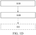
- FIG. 1D shows a schematic flowchart of another workflow construction method provided in an embodiment of the present application.
- the method may include the following steps: Step S11B: Function block node addition and connection operations performed on a GUI by a user on the basis of function block type graphs are received.
- the type graph and the label graph may be understood as two presentation manners of the same function block node, and are both used for implementing a corresponding service operation.
- FIG. 2T shows an example of constructing a behavior tree based on function block nodes of a function block type graph in an example.
- the function block type graph may include:
- a sensitive area 206 in a set range of the link input port 203 which is referred to as a first sensitive area here.
- first sensitive area When selection and line connection operations performed by a user are received in the first sensitive area, line connection end points are located on the link input port 203.
- second sensitive area there may also be a sensitive area (not shown in the figure) in a set range of the link output port 204, which is referred to as a second sensitive area here.
- line connection end points are located on the link output port 204.
- an instruction label 207 for indicating an execution sequence of the function block nodes may be further generated for the interconnected function block nodes F1 and F2, and the instruction label 207 is identified on the function block type graphs of the function block nodes F1 and F2, such as 1 and 2 shown in the figure.
- the instruction label 205 may also be used as an index for a jump instruction and as a chapter index for an instructional document.
- An input data chunk 208 for representing a set of all data input ports and an output data chunk 209 for representing a set of all data output ports may be identified on the input data chunk 208, such as 5 on the input data chunk 208 of the function block node F1 and 2 on the input data chunk 208 of the function block node F2. If the number of the data input ports is zero, the input data chunk 208 may be hidden. Similarly, the number of the data output ports of the function block nodes may be identified on the output data chunk 209, such as 3 on the output data chunk 209 of the function block node F1 and 1 on the output data chunk 209 of the function block node F2. If the number of the data output ports is zero, the output data chunk 209 may be hidden.
- the data input ports of the function block node may be expanded or hidden by clicking the input data chunk 208.
- the data output ports of the function block node may be expanded or hidden by clicking the output data chunk 209.
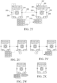
- FIG. 2U shows a schematic view of hiding a data input port of a logical node 2 by clicking.
- FIG. 2V shows a schematic view of hiding a data output port of a logical node 1 by clicking.
- FIG. 2W shows a schematic view of simultaneously displaying each data input port and each data output port.
- FIG. 2X shows a schematic view of simultaneously hiding each data input port and each data output port.
- the function block node connection operation may further include: a line connection operation between the data output port 211 and the data input port 210 between corresponding data of the two function block nodes F1 and F2.
- a data connection 212 is established between the two function block nodes F1 and F2.
- the data connection 212 in this example is used for indicating the data transmission between the two function block nodes F1 and F2. As shown in FIG.
- the data connection 212 is established between the data output port 211 of the output data 1 of the function block node F1 and the data input port 210 of the input data 2 of the function block node F2, indicating that the output data 1 of the function block node F1 serves as the input data 2 of the function block node F2.
- a sensitive area in a set range of the data input port 210, which is referred to as a third sensitive area here.
- a sensitive area in a set range of the data input port 210, which is referred to as a third sensitive area here.
- line connection end points are located on the data input port 210.
- a sensitive area in a set range of the data output port 211, which is referred to as a fourth sensitive area here.
- line connection end points are located on the data output port 211.
- the function block icon 213 may be a vector icon 213 for visually representing service operations of function block nodes.
- the function block icon 213 may also be omitted.
- the function block node addition operation may include: a dragging operation for the function block body 214.
- Step S12B In response to the function block node addition and connection operations, a behavior tree corresponding to one workflow is constructed.
- a behavior tree including flow control nodes and function block nodes based on a function block label graph in S 12A may be synchronously constructed.
- a behavior tree based on the function block type graph in S 12B may also be synchronously constructed.
- the construction interface of the two behavior trees may be switched according to the selection of the user.
- the behavior tree based on the function block type graph or the behavior tree based on the function block label graph by the user is switched and displayed.
- At least one data block may be further added and connected to each function block node in at least one function block node in the behavior tree.
- Each data block is used for presenting the corresponding data in the service operation of the function block node connected to the data block.
- the types of data blocks may include some or all of data pairs, data tables, images, videos and charts.
- FIG. 2Y shows a schematic view of respectively adding data blocks to four function block nodes in a behavior tree and displaying corresponding data in each data block in an example of the present application.
- a behavior tree creation interface based on a function block type graph is taken as an example. As shown in FIG.
- a data block with the type of live data-video is added to a function block node for production video recording associated with a monitor; a data block with the type of live data-text and a data block with the type of live data-chart are added to a function block node for screw fastening associated with a torque wrench; a data block with the type of live data-image is added to a function block node for robot image collection associated with a monitor; and a data block with the type of live data-video is added to a function block node for machine vision guidance associated with a camera.
- each data block may include a data block label 215 for indicating types of data blocks and a data block body 216 having a display area for presenting specific data.
- the data block label 215 may be a draggable label. For example, the data block label 215 may be moved to any position in a canvas.
- the size of the display area of the data block body 216 is adjustable for real-time display of different types of data from a data layer.
- a monitoring link 217 is established between each data block and the corresponding function block node, and one function block may be mapped to a plurality of data blocks. When a workflow is executed, for example, executed in a runtime, the monitoring and output data corresponding to the function block node will be transmitted to the corresponding data block for real-time display.
- the data block in this embodiment is a low code data block, which differs from other SCADA and dashboard systems in that: the low code data block in this embodiment is also a low code element, which may be used as a part of a behavior tree, and all attributes thereof may be managed in the low code logic.
- a data source in the low code data block is derived from the data layer, and data may be obtained through an interface provided by the data layer in a runtime or cloud execution engine.
- the data source may be a time series database, an RDBMS or a NoSQL.
- the low code data block is a flexible, scalable and adaptable system, which may be applied to any function block node that may be associated with a physical device.
- the data block for implementing data monitoring may be considered as a visual interface of the data layer.
- this embodiment may further include the following step S13 as shown by the dashed lines in FIG. 1A and FIG. 1B .
- Step S13 The behavior tree is analyzed, and the workflow corresponding to the behavior tree is deployed to a runtime of the corresponding workcell so that the runtime executes the workflow to control the resources in the workcell to execute the service operations according to the workflow.
- the runtime may further provide the corresponding data obtained during the execution of the service operation to the corresponding data block for displaying.
- the runtime may provide the corresponding data obtained during the execution of the service operation to the corresponding data block for displaying directly or through a third-party device.
- the workcell may include a main controller, and at this time, the runtime may be located on the main controller of the workcell.
- device resources in the resources may be connected to the main controller, and the main controller controls the connected device resources to execute corresponding operations according to the workflow of the runtime; and human resources and the like in the resources may directly execute corresponding operations according to workflow prompts of the runtime.
- the behavior tree may be stored in a Markup language such as an Extensible Markup Language (XML), and may be validated by an XML Schema (XSD) prototype to verify that the XML format of the behavior tree is correct.
- XML Extensible Markup Language
- XSD XML Schema
- the OT domain usually refers to an operational technology (OT), which combines hardware and software, and changes of processes or events in enterprises may be detected or triggered by directly monitoring and/or controlling physical devices (known as OT devices).
- OT uses a computer to monitor or change the physical state of an industrial control system (ICS), and the like.
- ICS is a facility, system or device implemented based on a computer, and is configured to remotely monitor and/or control critical industrial processes to implement physical functions.
- the term "OT" is used for distinguishing the ICS from the traditional information technology (IT) system in terms of technical implementations and functions.
- the above workflow construction method in this embodiment may be used for the OT domain, and serves as an OT-domain low code development method.
- the workflow construction method shown in FIG. 1A may be implemented on an OT domain such as an OT-domain low code development platform.
- the workflow may be an OT domain workflow;
- the workcell may be a workcell in the OT domain;
- the device may be an OT device.
- the OT device may include but is not limited to: an Internet of Things (IoT) device, a programmable logic controller (PLC), robotics, a manual process, an industrial personal computer (IPC), and the like.
- IoT Internet of Things
- PLC programmable logic controller
- IPC industrial personal computer
- the above workflow construction method in this embodiment may be used for the ITOT system, and serves as an OT-domain low code development method that may be fused with the IT domain.
- the workflow construction method shown in FIG. 1A may be implemented on an OT domain such as an OT-domain low code development platform.
- the workflow may be an OT domain workflow; and the workcell may be a workcell in the OT domain.
- the method further includes: a microservice is generated based on the behavior tree so that an IT device triggers the runtime of the main controller of the workcell to execute the OT domain workflow by calling the microservice.
- the IT device may directly call the microservice or call the microservice through a knowledge middle platform.
- the runtime may provide the corresponding data obtained during the execution of the service operation to the corresponding data block for displaying through the microservice.
- the runtime may provide the corresponding data obtained during the execution of the service operation to the knowledge middle platform, and the knowledge middle platform processes the data (including filtering) and then provides the data to the corresponding data block for displaying directly or through the microservice.
- an API for the microservice may be generated based on the behavior tree.
- the processing procedure in the API includes each operation in the OT domain workflow, input parameters of the API are parameters obtained from an input port of the OT domain workflow, and output parameters of the API are parameters outputted by an output port of the OT domain workflow.
- IT devices may include but are not limited to: a manufacturing operation management (MOM) system, a manufacturing execution system (MES), an enterprise resource planning (ERP) system, an enterprise service bus (ESB) system, a product lifecycle management (PLM) system, and the like.
- MOM manufacturing operation management
- MES manufacturing execution system
- ERP enterprise resource planning
- EMB enterprise service bus
- PLM product lifecycle management
- an IT-domain code development tool may be programmed to enable an IT device to call the microservice through a knowledge middle platform, so as to trigger the runtime of the main controller of the workcell to execute the OT domain workflow, thereby implementing the control of OT domain processes by the IT-domain code development platform, that is, implementing the fusion of the IT domain and the OT domain.
- the microservice is automatically generated by the OT domain microservice generator based on the OT domain behavior tree without the need for the IT-domain code development tool to understand the details of the OT domain workflow, and only an identifier (such as name) and an IP address of the microservice need to be obtained without the need for IT domain developers to understand OT domain devices and control processes, thereby being easy to implement and understand.
- the applicable fields of the embodiment of the present application include but are not limited to: industrial automation, logistics, laboratory, maritime, smart grid, electric vehicle infrastructure, electric vehicle, building automation, smart city, water treatment, garbage recycling, smart farm, and the like.
- the workflow construction method in the embodiment of the present application is described in detail above, and the workflow construction system in the embodiment of the present application will be described in detail below.
- the workflow construction system in the embodiment of the present application can be configured to implement the workflow construction method in the embodiment of the present application.
- the details not disclosed in detail in the system embodiment of the present invention can refer to the corresponding descriptions in the method embodiment of the present invention, which will not be repeated here.
- FIG. 3 shows a schematic structural view of a workflow construction system provided in an embodiment of the present application.
- the system may include: a node library 110, a graphical interface module 120 and an editing and processing module 130.
- Behavior tree nodes for constructing a behavior tree are arranged in the node library 110.
- the behavior tree nodes may include: flow control nodes and function block nodes.
- One behavior tree is used for representing one workflow, and the workflow is used for defining the operation to be executed by one workcell.
- the flow control nodes are used for implementing logical control in the workflow.
- the function block nodes are used for implementing service operations in the workflow.
- the function block nodes may include: logical nodes, where each logical node corresponds to one operation template, each operation template defines at least one type of resources in advance, such as the operations that can be executed by a device, and the operations include: actions, methods or skills.
- the node library 110 may further include various types of data blocks, and each data block is used for presenting the corresponding data in the service operation of the function block node connected to the data block.
- the types of the data blocks include: some or all of the data types such as data pairs, data tables, images, videos and charts.
- the resources are represented in the form of resource nodes, and all the resource nodes are associated and stored in the form of a resource knowledge graph.
- the resource knowledge graph includes: the resource nodes and connecting lines representing relationships among the resource nodes.
- the system further includes: a resource library 150, configured to store the resources in the form of a resource knowledge graph, where each resource can execute at least one service operation.
- the flow control nodes may include: some or all of main control nodes, logical control nodes and condition nodes.
- the main control nodes may include: some or all of a start node, an end node, a goto node, an anchor node, a stop node and an abort node.
- the logical control nodes include: some or all of an Se node, an RSe node, a Pa node, an IPQ node, a Pr node, an RPr node, an ITE node and an Sw node.
- the function block nodes may further include: some or all of a manual node, a dynamic node, a delay node and an empty (idle) node.
- the behavior tree nodes further include: a decorator node which may include: some or all of an Rp node, an Rt node, an OS node, a TO node, a Tm node, an Iv node, an FR node, an FO node, an FF node and a G node.
- a decorator node which may include: some or all of an Rp node, an Rt node, an OS node, a TO node, a Tm node, an Iv node, an FR node, an FO node, an FF node and a G node.
- some or all of the function block nodes in the node library 110 are respectively bound with resources that execute the service operations corresponding to the function block nodes.
- the function block nodes in the node library 110 may be presented in the form of label graphs as shown in FIG. 2A to FIG. 2T , or in the form of type graphs as shown in FIG. 2T to FIG. 2X .
- the function block nodes in the node library 110 may also be presented only in the form of a type graph. The specific structure of the function block nodes in the form of a function block type graph may be shown in FIG. 2T . The details are not repeated here.
- the graphical interface module 120 is configured to provide a GUI for users to perform behavior tree construction based on the behavior tree nodes in the node library 110.
- data block addition and connection operations may also be performed on the GUI.
- the GUI may include a first GUI for constructing a behavior tree based on flow control nodes and function block nodes in the form of a function block label graph, and a second GUI for constructing a behavior tree based on function block nodes in the form of a function block type graph, and the two GUIs may be switched and displayed according to the selection of users.
- the behavior tree construction operation may include function block node addition and connection operations.
- the function block node addition operation may include: a dragging operation for the function block body; and the function block node connection operation may include: a line connection operation between the link output port and the link input port between two function block nodes, and a line connection operation between the data output port and the data input port between corresponding data of two function block nodes.
- Each behavior tree node may be listed in the form of an icon on the GUI.
- the editing and processing module 130 is configured to generate a behavior tree corresponding to one workflow in response to the behavior tree construction operation.
- the editing and processing module 130 is also configured to add and connect at least one data block to each function block node in at least one function block node in the behavior tree in response to the data block addition and connection operations.
- the editing and processing module 130 can instantiate the behavior tree nodes and establish connection relationships among the instantiated behavior tree nodes in response to the behavior tree construction operation; and generate a behavior tree corresponding to one workflow based on the connection relationships among the instantiated behavior tree nodes.
- Some or all of the instantiated function block nodes are associated with resources for executing corresponding service operations. For example, through this operation, logical nodes are instantiated as operations of corresponding resources such as devices.
- each behavior tree node and each data block may be listed in the form of an icon on the GUI, and users can determine the nodes required for creating a workflow by selecting and dragging icons to be added to a canvas. Further, necessary parameter configuration, such as resource configuration and/or input and output parameter configuration, may also be performed on nodes.
- the behavior tree corresponding to the workflow may include multiple logical nodes, the execution sequence of the logical nodes is determined according to the sequence and relationships of operations, and the dragged nodes are arranged and connected correspondingly to finally generate a behavior tree corresponding to the workflow.
- the behavior tree construction operation may further include: an operation of associating resources with the added function block nodes.
- the workflow construction system in this embodiment may further include: an analyzing and deploying module 140, configured to analyze the behavior tree, and deploy the workflow corresponding to the behavior tree to a runtime of the corresponding workcell so that the runtime executes the workflow to control the resources in the workcell to execute the service operations according to the workflow.
- the corresponding data obtained during the execution of the service operation may be provided to the corresponding data block for displaying.
- the workcell may include a main controller, and at this time, the runtime may be located on the main controller of the workcell.
- device resources in the resources may be connected to the main controller, and the main controller controls the connected device resources to execute corresponding operations according to the workflow of the runtime; and human resources and the like in the resources may directly execute corresponding operations according to workflow prompts of the runtime.
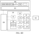
- FIG. 4A shows an OT-domain low code development platform 100 provided in an embodiment of the present application.
- the platform 100 can be configured to implement the workflow construction system shown in FIG. 3 .
- the OT-domain low code development platform 100 may include: an OT-domain low code development tool 10.
- the OT-domain low code development tool 10 may be configured to implement the graphical interface module 120 and the editing and processing module 130 in the workflow construction system shown in FIG. 3 , and further implement the analyzing and deploying module 140 in the workflow construction system shown in FIG. 3 .
- the node library 110 and resource library 150 in the workflow construction system shown in FIG. 3 may be stored on a memory.
- the OT-domain low code development platform 100 may further include a runtime 30 of the above workcell.
- the OT-domain low code development tool 10 can deploy the OT domain workflow corresponding to the generated behavior tree to the runtime 30 of the workcell, so that the runtime 30 executes the workflow to control various OT resources such as OT devices in the workcell to execute operations according to the OT domain workflow.
- the composition of the OT-domain low code development platform 100 shown in FIG. 4A and FIG. 4B only involves the OT domain. However, the fusion of the IT domain and the OT domain has become increasingly important for enterprise digital transformation. What needs to be achieved is how enterprises can use an easy-to-understand and non-IT-programming manner to control the processes of the OT domain.
- the OT-domain low code development platform 100 shown in FIG. 4C solves the problem of how to control the processes of the OT domain through an IT-domain code development platform 300. As shown in FIG. 4C , based on the structure shown in FIG. 4B , the OT-domain low code development platform 100 may further include an OT domain microservice generator 20 which can generate a microservice 40 based on an OT domain behavior tree.
- an IT-domain code development tool 301 may be programmed to enable an IT device to call the microservice 40 through a knowledge middle platform 200, so as to trigger the runtime 30 of the main controller of the workcell to execute the OT domain workflow, thereby implementing the control of OT domain processes by the IT-domain code development platform 300, that is, implementing the fusion of the IT domain and the OT domain.
- the microservice 40 is automatically generated by the OT domain microservice generator 20 based on the OT domain behavior tree without the need for the IT-domain code development tool 301 to understand the details of the OT domain workflow, and only an identifier (such as name) and an IP address of the microservice 40 need to be obtained without the need for IT domain developers to understand OT domain devices and control processes, thereby being easy to implement and understand.
- the OT domain microservice generator 20 can generate an API for the microservice 40 based on the OT domain behavior tree, where the processing procedure in the API may include the operation of each function block in the OT domain workflow, input parameters of the API are parameters obtained from an input port of the OT domain workflow, and output parameters of the API are parameters outputted by an output port of the OT domain workflow.
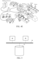
- FIG. 4E An application scenario of the OT-domain low code development platform 100 provided in an embodiment of the present application in the field of industrial automation is shown in FIG. 4E .
- the low code development tool 10 generates a behavior tree corresponding to the OT domain workflow under the operation of users, and the OT domain workflow defines the operation to be executed by a production line as a workcell shown on the right side in FIG. 4E .
- a corresponding workflow is generated based on the behavior tree and published to the runtime 30, so that the runtime 30 controls the completion of the production line operation of the workcell.
- a corresponding microservice can be generated by the microservice generator 20 and registered in the knowledge middle platform 200, so that the IT-domain code development tool 301 can call the corresponding microservice through the knowledge middle platform 200.
- Users can edit the OT domain behavior tree by dragging and editing various nodes including function block nodes as shown in the GUI at the lower left corner in FIG. 4E .
- the required data (such as workpiece processing parameters) can be obtained from a database and a server through the knowledge middle platform 200 to control the operation of the entire workcell.
- the workcell is a production line, and the production line includes machines, conveying belts, mechanical arms, personnel, PLCs, AGBs, and the like.
- the IT-domain code development tool 301 and the low code development tool 10 may be located on the same hardware device, such as on the same computer.
- FIG. 5 shows a schematic structural view of another workflow construction system provided in an embodiment of the present application.
- the system can be configured to implement the method shown in FIG. 1A , or implement the workflow construction system shown in FIG. 3 , or implement the workflow construction system according to any one of FIG. 4A to FIG. 4D , namely the OT-domain low code development platform 100.
- the above OT-domain low code development tool 10, OT domain microservice generator 20, runtime 30 and third-party apparatus 60 may all be implemented as separate hardware devices, such as servers, workstations, single chip microcomputers or processing chips.
- these apparatuses may be implemented on the same hardware device and stored as software programs in at least one memory, and the above OT-domain low code development method is implemented by calling at least one processor.
- the node library 110, the resource library 150 and each generated microservice 40 may be stored in at least one memory.
- the system may include: at least one memory 51, at least one processor 52 and at least one display 53.
- the system may also include some other components, such as communication ports (not shown in FIG. 5 ), and the like. These components communicate with each other through a bus 54.
- At least one memory 51 is configured to store computer programs. At least one memory 51 may include a computer-readable medium, such as a random access memory (RAM). In addition, at least one memory 51 may also store an operating system, and the like.
- the operating system includes but is not limited to: Android operating system, Symbian operating system, Windows operating system, Linux operating system, and the like.
- the above computer storage program may include the following program modules: a node library 110, a graphical interface module 120, an editing and processing module 130 and an analyzing and deploying module 140, and optionally may also include an OT domain microservice generator 20, a runtime 30 and a third-party apparatus 50.
- At least one processor 52 is configured to call the computer program stored in at least one memory 51 to execute the workflow construction method described in the embodiment of the present application.
- At least one processor 52 may be a microprocessor, an application specific integrated circuit (ASIC), a digital signal processor (DSP), a central processing unit (CPU), a graphics processing unit (GPU), a state machine, or the like. Data may be received and transmitted through the communication port.
- ASIC application specific integrated circuit
- DSP digital signal processor
- CPU central processing unit
- GPU graphics processing unit
- state machine or the like. Data may be received and transmitted through the communication port.
- At least one display 53 is configured to display a GUI.
- At least one processor 52 is configured to call the computer program stored in at least one memory 51, so that the system executes the operation in the workflow construction method described in any of the above implementations.
- a communication interface is configured to implement communication with other devices, such as communication with the knowledge middle platform 200.
- the OT-domain low code development tool 10 for implementing the graphical interface module 120, the editing and processing module 130 and the analyzing and deploying module 140 may be a lightweight web-based application, which may be implemented on industrial sites (such as edge devices or local servers), or may be implemented on the cloud side (public clouds such as AWS or private clouds such as OpenStack).
- a visual engineering paradigm is derived from a function block typed diagram (FBTD).
- the OT domain microservice generator 20 may use modern translation programming languages to generate a standard API such as RESTful or RPC.
- the runtime 30 may simply implement the OT domain workflow and provide openness based on an ecosystem of an open source community (such as Python).
- the runtime 30 may be deployed on an embedded IoT device such as a single board computer (SBC).
- SBC single board computer
- the embodiment of the present application may include an apparatus with an architecture different from that shown in FIG. 5 .
- the above architecture is only illustrative and is configured to explain a workflow construction method provided in the embodiment of the present application.
- an embodiment of the present application further provides an IT domain and OT domain fusion system, namely an ITOT system, which may include an IT device and a workflow construction system in any implementation of the present application.
- the system may further include: an IT-domain code development platform 300 shown in FIG. 4C and FIG. 4D .
- an embodiment of the present application further provides a computer-readable storage medium.
- the computer-readable storage medium stores computer-readable codes, and the computer-readable codes, when executed by a processor, cause the processor to execute the above workflow construction method.
- an embodiment of the present application further provides a computer program product.
- the computer program product is tangibly stored on a computer-readable medium and includes computer-readable instructions, and the computer-readable instructions, when executed, cause at least one processor to execute the steps in the workflow construction method in the embodiment of the present application.
- a system or an apparatus provided with a storage medium may be provided.
- the storage medium stores computer-readable codes for implementing functions of any implementation in the above embodiment, and a computer (or a CPU or an MPU) of the system or the apparatus is enabled to read and execute the computer-readable codes stored in the storage medium.
- the operating system and the like operated on the computer may complete some or all of the actual operations through instructions based on the computer-readable codes.
- the computer-readable codes read from the storage medium may also be written to the memory arranged in an expansion board inserted into the computer, or written to the memory in an expansion unit connected to the computer, and then, instructions based on the computer-readable codes cause the CPU and the like installed on the expansion board or the expansion unit to execute some or all of the actual operations, thereby implementing the functions of any of the above implementations.
- examples of the computer-readable medium include but are not limited to a floppy disk, a CD-ROM, a magnetic disk, an optical disk (such as CD-ROM, CD-R, CD-RW, DVD-ROM, DVD-RAM, DVD-RW, or DVD+RW), a memory chip, an ROM, an RAM, an ASIC, a configured processor, an all-optical medium, all magnetic tapes or other magnetic media, or any other medium from which a computer processor can read instructions.
- various other forms of computer-readable media may transmit or carry instructions to a computer, including routers, private or public networks, or other wired and wireless transmission devices or channels.
- computer-readable instructions may be downloaded from a server computer or cloud through a communication network. Instructions may include codes of any computer programming language, including C, C++, C language, Visual Basic, java and JavaScript.
- the system structure described in the above embodiments may be a physical structure or a logical structure. That is, some modules may be implemented by the same physical entity, or some modules may be implemented by a plurality of physical entities, or may be implemented by some components in a plurality of independent devices together.
Landscapes
- Engineering & Computer Science (AREA)
- Theoretical Computer Science (AREA)
- Business, Economics & Management (AREA)
- Physics & Mathematics (AREA)
- General Physics & Mathematics (AREA)
- Human Resources & Organizations (AREA)
- General Engineering & Computer Science (AREA)
- Software Systems (AREA)
- Strategic Management (AREA)
- Entrepreneurship & Innovation (AREA)
- Economics (AREA)
- General Business, Economics & Management (AREA)
- Tourism & Hospitality (AREA)
- Quality & Reliability (AREA)
- Operations Research (AREA)
- Marketing (AREA)
- Automation & Control Theory (AREA)
- Computational Linguistics (AREA)
- Data Mining & Analysis (AREA)
- Development Economics (AREA)
- Educational Administration (AREA)
- Game Theory and Decision Science (AREA)
- Human Computer Interaction (AREA)
- Management, Administration, Business Operations System, And Electronic Commerce (AREA)
Applications Claiming Priority (1)
| Application Number | Priority Date | Filing Date | Title |
|---|---|---|---|
| PCT/CN2022/075085 WO2023142078A1 (zh) | 2022-01-29 | 2022-01-29 | 工作流构建方法、系统、介质及程序产品 |
Publications (2)
| Publication Number | Publication Date |
|---|---|
| EP4455869A1 true EP4455869A1 (de) | 2024-10-30 |
| EP4455869A4 EP4455869A4 (de) | 2025-10-22 |
Family
ID=87470274
Family Applications (1)
| Application Number | Title | Priority Date | Filing Date |
|---|---|---|---|
| EP22922908.3A Pending EP4455869A4 (de) | 2022-01-29 | 2022-01-29 | Arbeitsflusskonstruktionsverfahren und -system, medium und programmprodukt |
Country Status (4)
| Country | Link |
|---|---|
| US (1) | US20250130545A1 (de) |
| EP (1) | EP4455869A4 (de) |
| CN (1) | CN118541671A (de) |
| WO (1) | WO2023142078A1 (de) |
Families Citing this family (1)
| Publication number | Priority date | Publication date | Assignee | Title |
|---|---|---|---|---|
| US12561151B1 (en) * | 2025-03-20 | 2026-02-24 | Pramana, Inc. | Modular data acquisition and analysis system and methods thereof |
Family Cites Families (8)
| Publication number | Priority date | Publication date | Assignee | Title |
|---|---|---|---|---|
| CN102495868B (zh) * | 2011-11-30 | 2013-11-20 | 国家电网公司 | 电能量采集与监控系统图形监控的实现方法 |
| CN103838563B (zh) * | 2012-11-27 | 2017-07-28 | 台博机器人股份有限公司 | 自动装置的程序开发方法 |
| US11546380B2 (en) * | 2015-10-28 | 2023-01-03 | Qomplx, Inc. | System and method for creation and implementation of data processing workflows using a distributed computational graph |
| CN106250100B (zh) * | 2016-08-15 | 2018-05-11 | 腾讯科技(深圳)有限公司 | 系统逻辑控制方法及装置 |
| CN109522005A (zh) * | 2018-11-15 | 2019-03-26 | 苏州友教习亦教育科技有限公司 | 跨平台图形化程序设计方法 |
| EP3712787B1 (de) * | 2019-03-18 | 2021-12-29 | Siemens Aktiengesellschaft | Verfahren zum erzeugen einer semantischen beschreibung einer zusammengesetzten interaktion |
| CN113515272A (zh) * | 2020-04-09 | 2021-10-19 | 深圳轩科华智能科技有限公司 | 一种可视化编程的方法和系统 |
| EP3926422A1 (de) * | 2020-06-17 | 2021-12-22 | Siemens Aktiengesellschaft | Verfahren zur programmierung mindestens einer maschine in einem industriellen automatisierungssystem |
-
2022
- 2022-01-29 US US18/834,021 patent/US20250130545A1/en active Pending
- 2022-01-29 CN CN202280089264.1A patent/CN118541671A/zh active Pending
- 2022-01-29 EP EP22922908.3A patent/EP4455869A4/de active Pending
- 2022-01-29 WO PCT/CN2022/075085 patent/WO2023142078A1/zh not_active Ceased
Also Published As
| Publication number | Publication date |
|---|---|
| WO2023142078A1 (zh) | 2023-08-03 |
| EP4455869A4 (de) | 2025-10-22 |
| CN118541671A (zh) | 2024-08-23 |
| US20250130545A1 (en) | 2025-04-24 |
Similar Documents
| Publication | Publication Date | Title |
|---|---|---|
| EP4459525A1 (de) | Verfahren und system zur arbeitsablauferzeugung sowie medium und programmprodukt | |
| WO2023164841A1 (zh) | 工作流执行方法、装置、存储介质及程序产品 | |
| WO2023004806A1 (zh) | Ai模型的设备部署方法、系统及存储介质 | |
| EP4455814A1 (de) | Arbeitsflusssteuerungsverfahren, -vorrichtung und -system sowie medium und programmprodukt | |
| EP4459398A1 (de) | Arbeitsflusserzeugungsverfahren, -vorrichtung und -system, -medium und -programmprodukt | |
| EP4455869A1 (de) | Arbeitsflusskonstruktionsverfahren und -system, medium und programmprodukt | |
| CN113961174A (zh) | 一种基于云原生微服务的模型开发与部署方法 | |
| EP4462299A1 (de) | Verfahren und system zur implementierung eines dynamischen arbeitsablaufs, medium und programmprodukt | |
| WO2023142079A1 (zh) | 工作流创建方法、系统、介质及程序产品 | |
| EP4455956A1 (de) | Arbeitsflusskonstruktion und überwachungsverfahren und -system sowie medium und programmprodukt | |
| EP4471687A1 (de) | Arbeitsflussausführungsverfahren und -system, medium und programmprodukt | |
| EP4459470A1 (de) | Arbeitsflusserzeugungsverfahren, -vorrichtung und -system, -medium und -programmprodukt | |
| EP4465614A1 (de) | Arbeitsflussausführungsverfahren und -vorrichtung, speichermedium und programmprodukt | |
| US20250130556A1 (en) | Workflow Creation Method, Apparatus and Platform | |
| EP4495824A1 (de) | Umwandlungsverfahren und -vorrichtung für natürliche sprachsätze und speichermedium | |
| Yu et al. | The implementation of IEC60870-5-104 based on UML statechart and Qt state machine framework | |
| Rumiantcev et al. | Automatic testing of IEC 61499 automation systems with simulator in the loop in cloud environment | |
| Plasch | Model-based generation of an IEC 61499 control application for a flexible robot system | |
| Matikainen | Development of a test framework for power converter software releases: case Visedo PowerMASTER series |
Legal Events
| Date | Code | Title | Description |
|---|---|---|---|
| STAA | Information on the status of an ep patent application or granted ep patent |
Free format text: STATUS: THE INTERNATIONAL PUBLICATION HAS BEEN MADE |
|
| PUAI | Public reference made under article 153(3) epc to a published international application that has entered the european phase |
Free format text: ORIGINAL CODE: 0009012 |
|
| STAA | Information on the status of an ep patent application or granted ep patent |
Free format text: STATUS: REQUEST FOR EXAMINATION WAS MADE |
|
| 17P | Request for examination filed |
Effective date: 20240726 |
|
| AK | Designated contracting states |
Kind code of ref document: A1 Designated state(s): AL AT BE BG CH CY CZ DE DK EE ES FI FR GB GR HR HU IE IS IT LI LT LU LV MC MK MT NL NO PL PT RO RS SE SI SK SM TR |
|
| DAV | Request for validation of the european patent (deleted) | ||
| DAX | Request for extension of the european patent (deleted) | ||
| REG | Reference to a national code |
Ref country code: DE Ref legal event code: R079 Free format text: PREVIOUS MAIN CLASS: G06F0009300000 Ipc: G06F0008340000 |
|
| A4 | Supplementary search report drawn up and despatched |
Effective date: 20250919 |
|
| RIC1 | Information provided on ipc code assigned before grant |
Ipc: G06F 8/34 20180101AFI20250915BHEP Ipc: G05B 19/042 20060101ALI20250915BHEP Ipc: G06F 8/30 20180101ALI20250915BHEP Ipc: G06F 9/50 20060101ALI20250915BHEP Ipc: G06Q 10/0633 20230101ALI20250915BHEP Ipc: G06Q 10/06 20230101ALI20250915BHEP Ipc: G06F 9/54 20060101ALI20250915BHEP Ipc: G06F 9/455 20180101ALI20250915BHEP Ipc: G06F 30/17 20200101ALI20250915BHEP Ipc: G06F 30/12 20200101ALI20250915BHEP Ipc: G06F 3/0486 20130101ALI20250915BHEP Ipc: G06F 9/445 20180101ALN20250915BHEP Ipc: G06F 8/36 20180101ALN20250915BHEP Ipc: G05B 19/05 20060101ALN20250915BHEP Ipc: G06F 8/41 20180101ALN20250915BHEP Ipc: G06F 8/60 20180101ALN20250915BHEP |