EP4455841A1 - Verfahren und vorrichtung zur einstellung eines anwendungsfensters, vorrichtung und medium - Google Patents
Verfahren und vorrichtung zur einstellung eines anwendungsfensters, vorrichtung und medium Download PDFInfo
- Publication number
- EP4455841A1 EP4455841A1 EP24171721.4A EP24171721A EP4455841A1 EP 4455841 A1 EP4455841 A1 EP 4455841A1 EP 24171721 A EP24171721 A EP 24171721A EP 4455841 A1 EP4455841 A1 EP 4455841A1
- Authority
- EP
- European Patent Office
- Prior art keywords
- movement
- cursor
- application window
- target application
- adjustment
- Prior art date
- Legal status (The legal status is an assumption and is not a legal conclusion. Google has not performed a legal analysis and makes no representation as to the accuracy of the status listed.)
- Pending
Links
Images






Classifications
-
- G—PHYSICS
- G06—COMPUTING OR CALCULATING; COUNTING
- G06F—ELECTRIC DIGITAL DATA PROCESSING
- G06F3/00—Input arrangements for transferring data to be processed into a form capable of being handled by the computer; Output arrangements for transferring data from processing unit to output unit, e.g. interface arrangements
- G06F3/01—Input arrangements or combined input and output arrangements for interaction between user and computer
- G06F3/011—Arrangements for interaction with the human body, e.g. for user immersion in virtual reality
- G06F3/013—Eye tracking input arrangements
-
- G—PHYSICS
- G06—COMPUTING OR CALCULATING; COUNTING
- G06F—ELECTRIC DIGITAL DATA PROCESSING
- G06F3/00—Input arrangements for transferring data to be processed into a form capable of being handled by the computer; Output arrangements for transferring data from processing unit to output unit, e.g. interface arrangements
- G06F3/01—Input arrangements or combined input and output arrangements for interaction between user and computer
- G06F3/03—Arrangements for converting the position or the displacement of a member into a coded form
- G06F3/033—Pointing devices displaced or positioned by the user, e.g. mice, trackballs, pens or joysticks; Accessories therefor
- G06F3/0346—Pointing devices displaced or positioned by the user, e.g. mice, trackballs, pens or joysticks; Accessories therefor with detection of the device orientation or free movement in a three-dimensional [3D] space, e.g. 3D mice, 6-DOF [six degrees of freedom] pointers using gyroscopes, accelerometers or tilt-sensors
-
- G—PHYSICS
- G06—COMPUTING OR CALCULATING; COUNTING
- G06F—ELECTRIC DIGITAL DATA PROCESSING
- G06F3/00—Input arrangements for transferring data to be processed into a form capable of being handled by the computer; Output arrangements for transferring data from processing unit to output unit, e.g. interface arrangements
- G06F3/01—Input arrangements or combined input and output arrangements for interaction between user and computer
- G06F3/048—Interaction techniques based on graphical user interfaces [GUI]
- G06F3/0481—Interaction techniques based on graphical user interfaces [GUI] based on specific properties of the displayed interaction object or a metaphor-based environment, e.g. interaction with desktop elements like windows or icons, or assisted by a cursor's changing behaviour or appearance
-
- G—PHYSICS
- G06—COMPUTING OR CALCULATING; COUNTING
- G06F—ELECTRIC DIGITAL DATA PROCESSING
- G06F3/00—Input arrangements for transferring data to be processed into a form capable of being handled by the computer; Output arrangements for transferring data from processing unit to output unit, e.g. interface arrangements
- G06F3/01—Input arrangements or combined input and output arrangements for interaction between user and computer
- G06F3/048—Interaction techniques based on graphical user interfaces [GUI]
- G06F3/0481—Interaction techniques based on graphical user interfaces [GUI] based on specific properties of the displayed interaction object or a metaphor-based environment, e.g. interaction with desktop elements like windows or icons, or assisted by a cursor's changing behaviour or appearance
- G06F3/04815—Interaction with a metaphor-based environment or interaction object displayed as three-dimensional [3D], e.g. changing the user viewpoint with respect to the environment or object
-
- G—PHYSICS
- G06—COMPUTING OR CALCULATING; COUNTING
- G06F—ELECTRIC DIGITAL DATA PROCESSING
- G06F3/00—Input arrangements for transferring data to be processed into a form capable of being handled by the computer; Output arrangements for transferring data from processing unit to output unit, e.g. interface arrangements
- G06F3/01—Input arrangements or combined input and output arrangements for interaction between user and computer
- G06F3/048—Interaction techniques based on graphical user interfaces [GUI]
- G06F3/0484—Interaction techniques based on graphical user interfaces [GUI] for the control of specific functions or operations, e.g. selecting or manipulating an object, an image or a displayed text element, setting a parameter value or selecting a range
-
- G—PHYSICS
- G06—COMPUTING OR CALCULATING; COUNTING
- G06F—ELECTRIC DIGITAL DATA PROCESSING
- G06F3/00—Input arrangements for transferring data to be processed into a form capable of being handled by the computer; Output arrangements for transferring data from processing unit to output unit, e.g. interface arrangements
- G06F3/01—Input arrangements or combined input and output arrangements for interaction between user and computer
- G06F3/048—Interaction techniques based on graphical user interfaces [GUI]
- G06F3/0484—Interaction techniques based on graphical user interfaces [GUI] for the control of specific functions or operations, e.g. selecting or manipulating an object, an image or a displayed text element, setting a parameter value or selecting a range
- G06F3/04845—Interaction techniques based on graphical user interfaces [GUI] for the control of specific functions or operations, e.g. selecting or manipulating an object, an image or a displayed text element, setting a parameter value or selecting a range for image manipulation, e.g. dragging, rotation, expansion or change of colour
-
- G—PHYSICS
- G06—COMPUTING OR CALCULATING; COUNTING
- G06F—ELECTRIC DIGITAL DATA PROCESSING
- G06F3/00—Input arrangements for transferring data to be processed into a form capable of being handled by the computer; Output arrangements for transferring data from processing unit to output unit, e.g. interface arrangements
- G06F3/01—Input arrangements or combined input and output arrangements for interaction between user and computer
- G06F3/048—Interaction techniques based on graphical user interfaces [GUI]
- G06F3/0487—Interaction techniques based on graphical user interfaces [GUI] using specific features provided by the input device, e.g. functions controlled by the rotation of a mouse with dual sensing arrangements, or of the nature of the input device, e.g. tap gestures based on pressure sensed by a digitiser
-
- G—PHYSICS
- G06—COMPUTING OR CALCULATING; COUNTING
- G06F—ELECTRIC DIGITAL DATA PROCESSING
- G06F3/00—Input arrangements for transferring data to be processed into a form capable of being handled by the computer; Output arrangements for transferring data from processing unit to output unit, e.g. interface arrangements
- G06F3/01—Input arrangements or combined input and output arrangements for interaction between user and computer
- G06F3/048—Interaction techniques based on graphical user interfaces [GUI]
- G06F3/0487—Interaction techniques based on graphical user interfaces [GUI] using specific features provided by the input device, e.g. functions controlled by the rotation of a mouse with dual sensing arrangements, or of the nature of the input device, e.g. tap gestures based on pressure sensed by a digitiser
- G06F3/0489—Interaction techniques based on graphical user interfaces [GUI] using specific features provided by the input device, e.g. functions controlled by the rotation of a mouse with dual sensing arrangements, or of the nature of the input device, e.g. tap gestures based on pressure sensed by a digitiser using dedicated keyboard keys or combinations thereof
Definitions
- Embodiments of the present application relate to the technical field of extended reality (XR), and in particular, to an application window adjustment method and apparatus, a device, and a medium.
- XR extended reality
- XR devices may have a large number of three-dimensional application programs (3D applications) and a large number of two-dimensional application programs (2D applications) installed thereon, to meet various usage requirements of users.
- 3D applications three-dimensional application programs
- 2D applications two-dimensional application programs
- the present application provides an application window adjustment method and apparatus, a device, and a medium, by which the purpose of adjusting a 2D application window in a virtual space is achieved, so that the need of a user to adjust the 2D application window is met, and the user experience is improved.
- an embodiment of the present application provides an application window adjustment method, the method including:
- an embodiment of the present application provides an application window adjustment apparatus, the apparatus including:
- an embodiment of the present application provides an electronic device, the device including: a processor and a memory, where the memory is configured to store a computer program, and the processor is configured to call and run the computer program stored in the memory, to perform the application window adjustment method according to the embodiment of the first aspect or various implementations thereof.
- an embodiment of the present application provides a computer-readable storage medium, which is configured to store a computer program, where the computer program causes a computer to perform the application window adjustment method according to the embodiment of the first aspect or various implementations thereof.
- an embodiment of the present application provides a computer program product including program instructions, where the program instructions, when run on an electronic device, cause the electronic device to perform the application window adjustment method according to the embodiment of the first aspect or various implementations thereof.
- the target application window is displayed in the virtual space in response to the selection instruction for the target application; when the trigger operation for the target button on the controller is detected, the display position of the cursor corresponding to the controller is obtained; and when the display position of the cursor is located on the target application window, the target application window is adjusted based on the movement trajectory of the cursor.
- an application window adjustment function is set in association with any button on the controller, so that the user can enable the application window adjustment function by triggering the button on the controller, and then adjust an application window displayed in the virtual space by manipulating the controller. In this way, with full use of freedom and flexibility of the controller in the space, the purpose of adjusting a 2D application window in the virtual space is achieved, so that the need of the user to adjust the 2D application window is met, and the user experience is improved.
- the term "exemplary”, “for example”, etc. is used to represent an example, an illustration, or a description. Any embodiment or solution described by “exemplary” or “for example” in the embodiments of the present application should not be construed as being preferred or advantageous over other embodiments or solutions. To be precise, the term “exemplary” or “for example” is intended to present a related concept in a specific manner.
- the present application provides an application window adjustment solution.
- the solution with the use of freedom and flexibility of a controller in the space, the purpose of adjusting the 2D application window in the virtual space can be achieved, so that the need of the user to adjust the 2D application window is met, and the user experience is improved.
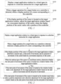
- FIG. 1 is a schematic flowchart of an application window adjustment method according to an embodiment of the present application.
- the application window adjustment method according to this embodiment of the present application may be performed by an application window adjustment apparatus.
- the application window adjustment apparatus may be composed of hardware and/or software, and may be integrated into an electronic device.
- the electronic device may be any hardware device capable of providing a virtual space.
- the electronic device is an XR device, a mobile phone (such as a foldable phone or a large-screen phone), a tablet computer, etc.
- the specific type of the electronic device is not specifically limited in the present application.
- the XR device may be a VR device, an AR device, an MR device, etc.
- the method includes the following steps.
- S101 Display a target application window in a virtual space in response to a selection instruction for a target application.
- the virtual space is a virtual environment that is provided for a user by the electronic device by combining a real scene and a virtual scene and that allows for human-computer interaction.
- the virtual space may be displayed as a three-dimensional image.
- the target application is preferably a 2D application.
- the user turns on the electronic device so that the electronic device enters a working state.
- the electronic device may simulate, for the user, the virtual environment that is used to display various types of media content for various types of user interaction, so that the user may enter a corresponding virtual space.
- the user may select any target application in the virtual space to perform a corresponding operation. For example, the user may select a 2D browser, and then allow the 2D browser to run and perform an information search operation, etc. That is, when a selection instruction for any target application in the virtual space by the user is detected, the target application is opened in the virtual space, and an application window of the target application is presented.
- the user may select any target application in the virtual space through eye tracking by gazing at the target application for a preset duration, to send the selection instruction for the target application to the electronic device.
- the preset duration may be flexibly set, for example, to 3 seconds (s) or 5s, according to actual requirements.
- the user may select the target application in other ways, such as by moving a controller to control a cursor to move onto the target application and pressing a confirm button (such as a home button) on the controller, to send the selection instruction for the target application to the electronic device, which is not specifically limited herein.
- the controller may be but is not limited to: a controller grip, a hand controller, and other handheld devices with a button.
- the target button on the controller may be any button on the controller.
- the button may be any one of the buttons on the controller, such as a trigger button Grip or a joystick.
- the button may be a combination of buttons on the controller, such as of a trigger button Grip and a menu button.
- the button may be flexibly set according to actual application requirements, which is not specifically limited herein.
- a corresponding application window adjustment function may be preconfigured, on the electronic device, for the target button on the controller, so that once the user presses the target button after opening the target application, the electronic device can determine that the user triggers the application window adjustment function. Then, the electronic device enables and runs the application window adjustment function. As such, the user adjusts the target application window displayed in the virtual space based on the enabled application window adjustment function.
- the target application window presented in the virtual space may occlude any interaction object in the virtual space, such as a live streamer, a prop, or other objects.
- the user may need to adjust the target application window, to avoid occlusion of the interaction object in the virtual space.
- the user may have a need to adjust the target application window.
- the user may trigger (press) the target button on the controller that is associated with the application window adjustment function, to send to the electronic device an instruction to enable the application window adjustment function. Then, the electronic device enables the application window adjustment function associated with the target button based on the detection of the trigger operation for the target button. After the application window adjustment function is enabled, the display position of the cursor corresponding to the controller is obtained, so that it is determined whether to perform an application window adjustment operation based on the display position of the cursor.
- the display position of the cursor is usually located at an upper layer of an interaction interface in the virtual space, and is used to mark position information of the controller.
- a display shape of the cursor may be a dot, a circle, an angled arrow, crossed arrows, a hand shape, etc., which is not specifically limited herein.
- the controller may actively send pose information of its own to the electronic device at a preset time interval.
- the pose information includes position information and posture information.
- the pose information is relative pose information of the controller in a real space where the user is located.
- the above preset time interval may be flexibly set based on a data display delay of the electronic device. For example, for a short delay, a small preset time interval is set, and for a long delay, a large preset time interval is set.
- pose data of the controller may be obtained through a sensor mounted in the controller.
- the sensor includes but is not limited to: an inertial measurement unit (IMU for short), a nine-axis sensor, a triaxial sensor, a gyroscope, an accelerometer, and a magnetometer.
- IMU inertial measurement unit
- the sensor includes but is not limited to: an inertial measurement unit (IMU for short), a nine-axis sensor, a triaxial sensor, a gyroscope, an accelerometer, and a magnetometer.
- IMU inertial measurement unit
- the electronic device may determine the display position of the cursor based on the pose information sent by the controller, and mark the cursor at the determined display position. As such, when a subsequent change in a position of the controller occurs, the display position of the cursor changes accordingly.
- the user may suddenly not want to continue to adjust the target application window, or may not be able to continue to perform the application window adjustment operation due to the need to perform other operations, etc.
- the user may release the pressed target button to cancel the application window adjustment operation, such that when detecting that the target button on the controller is released, the electronic device stops the adjustment operation on the target application window, and disables the enabled application window adjustment function, so as to achieve the effect of saving energy of the device.
- the adjusting the target application window includes at least one of the following: making a position adjustment for the target application window; making a direction adjustment for the target application window; making an angle adjustment for the target application window; and making a size adjustment for the target application window.
- the display position of the cursor after the display position of the cursor is determined, in the present application, it may be determined whether the display position of the cursor is located on the target application window. If it is determined that the display position of the cursor is located on the target application window, it indicates that the user is about to perform the application window adjustment operation. Otherwise, it indicates that the user has not started to perform the application window adjustment operation, in which case continuous obtaining of the display position of the cursor and determination of whether the display position of the cursor is located on the target application window are performed, until the display position of the cursor is located on the target application window, or the user cancels the application window adjustment operation.
- the determining whether the display position of the cursor is located on the target application window is specifically determining whether the display position of the cursor is located within a range of coordinates of all points in the planar region corresponding to the target application window. If the display position of the cursor is located within the range of coordinates of all points in the planar region corresponding to the target application window, it indicates that the cursor is located on the target application window. If the display position of the cursor is not located within the range of coordinates of all points in the planar region corresponding to the target application window, it indicates that the cursor is not located on the target application window.
- the user may adjust the target application window by moving the controller. Therefore, when it is determined that the display position of the cursor is located on the target application window, in the present application, the movement trajectory of the cursor corresponding to the controller may first be obtained, and the target application window is then adjusted based on the movement trajectory of the cursor.
- adjusting the target application window based on the movement trajectory of the cursor may involve: determining a motion type of the cursor, and a start point of movement and an end point of movement of the cursor based on the movement trajectory of the cursor, and then adjusting a position, a direction, an corner point, and/or a size of the target application window based on the motion type of the cursor, and the start point of movement and the end point of movement of the cursor.
- the target application window is displayed in the virtual space in response to the selection instruction for the target application; when the trigger operation for the target button on the controller is detected, the display position of the cursor corresponding to the controller is obtained; and when the display position of the cursor is located on the target application window, the target application window is adjusted based on the movement trajectory of the cursor.
- an application window adjustment function is set in association with any button on the controller, so that the user can enable the application window adjustment function by triggering the button on the controller, and then adjust an application window displayed in the virtual space by manipulating the controller. In this way, with full use of freedom and flexibility of the controller in the space, the purpose of adjusting a 2D application window in the virtual space is achieved, so that the need of the user to adjust the 2D application window is met, and the user experience is improved.
- the motion type of the cursor may be a curvilinear motion or a rectilinear motion based on the movement trajectory of the cursor.
- a detailed description of the adjustment for the target application window based on the rectilinear motion, the start point of movement of the cursor, and the end point of movement of the cursor when the motion type of the cursor is the rectilinear motion in the present application is specifically provided below with reference to FIG. 2 .
- the method includes the following steps.
- S201 Display a target application window in a virtual space in response to a selection instruction for a target application.
- the start point of movement and the end point of movement of the cursor may be determined.
- the motion type of the cursor the movement trajectory of the cursor may be analyzed and processed in different manners, to determine whether the motion type of the cursor is the rectilinear motion or the curvilinear motion.
- the movement trajectory of the cursor may be analyzed and processed by using a force analysis method, an analytic method, a drawing method, or other methods, which is not specifically limited herein.
- the motion type of the cursor is the curvilinear motion; or if it is determined that the movement trajectory of the cursor is the straight line, it indicates that the motion type of the cursor is the rectilinear motion.
- S204 When the motion type of the cursor is the rectilinear motion, determine whether the start point of movement of the cursor is located on a window border of the target application window. If the start point of movement of the cursor is located on the window border, S205 is performed; otherwise, S206 is performed.
- the target application window corresponds to a planar region
- a window border part and a window main body part in the planar region are known.
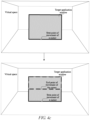
- the window border part and the window main body part each are composed of a plurality of points. Therefore, in the present application, the start point of movement of the cursor may be compared with a range of coordinates of points corresponding to the window border part. If the start point of movement of the cursor is located within the range of coordinates of points corresponding to the window border part, it is determined that the start point of movement of the cursor is located on the window border of the target application window.
- start point of movement of the cursor is not located within the range of coordinates of points corresponding to the window border part but within a range of coordinates of points corresponding to the window main body part, it is determined that the start point of movement of the cursor is located on a window main body of the target application window.
- the start point of movement of the cursor is located on the window border of the target application window, as shown in FIG. 3a ; and the start point of movement of the cursor is located on the window main body of the target application window, as shown in FIG. 3b .
- Making the size adjustment for the target application window may be understood as adjusting the size of the target application window.
- making the size adjustment for the target application window may involve controlling, with the start point of movement of the cursor as a start point, the window border of the target application window to move from the start point of movement of the cursor to the end point of movement of the cursor, to make the size adjustment for the target application window.
- a shape of the target application window may be a circle, a rectangle, etc.
- an overall height and length adjustment for the circular target application window may be made based on the start point of movement and the end point of movement of the cursor, for example, as shown in FIG. 4a .
- a rectangular target application window may be composed of four window borders, namely, top, bottom, left, and right window borders. Therefore, in the present application, making the size adjustment for the rectangular target application window based on the start point of movement and the end point of movement of the cursor specifically involves the followings cases.
- making the size adjustment for the rectangular target application window is specifically making a height adjustment for the target application window.
- FIG. 4b shows a manner of making the height adjustment for the target application window.
- making the size adjustment for the rectangular target application window is specifically making a height adjustment for the target application window.
- FIG. 4c shows another manner of making the height adjustment for the target application window.
- making the size adjustment for the rectangular target application window is specifically making a length adjustment for the target application window.
- FIG. 4d shows a manner of making the length adjustment for the target application window.
- making the size adjustment for the rectangular target application window is specifically making a length adjustment for the target application window.
- FIG. 4e shows another manner of making the length adjustment for the target application window.
- the rectangular target application window includes four vertices, namely, a top-left vertex, a top-right vertex, a bottom-right vertex, and a bottom-left vertex. Therefore, when it is determined that the start point of movement of the cursor is located at a window edge and at any vertex of the window edge, in the present application, an overall length and width adjustment for the target application window may be made based on the start point of movement and the end point of movement of the cursor.
- making the size adjustment for the rectangular target application window is specifically making a length and height adjustment for the target application window.
- the direction adjustment for the target application window is also made while the position adjustment is made for the target application window.
- making the position adjustment and the direction adjustment for the target application window may involve controlling, with the start point of movement of the cursor as a start point, the target application window to move from the start point position of movement of the cursor to the end point of movement of the cursor, thereby making the position adjustment and the direction adjustment for the target application window.
- the target application window may be moved from the position A1 to the position A2, to implement both the position and direction adjustments for the target application window.
- the target application window is displayed in the virtual space in response to the selection instruction for the target application; when the trigger operation for the target button on the controller is detected, the display position of the cursor corresponding to the controller is obtained; and when the display position of the cursor is located on the target application window, the target application window is adjusted based on the movement trajectory of the cursor.
- an application window adjustment function is set in association with any button on the controller, so that the user can enable the application window adjustment function by triggering the button on the controller, and then adjust an application window displayed in the virtual space by manipulating the controller. In this way, with full use of freedom and flexibility of the controller in the space, the purpose of adjusting a 2D application window in the virtual space is achieved, so that the need of the user to adjust the 2D application window is met, and the user experience is improved.
- the motion type of the cursor may be a curvilinear motion or a rectilinear motion based on the movement trajectory of the cursor.
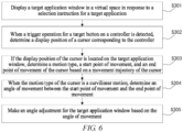
- a detailed description of the adjustment for the target application window based on the curvilinear motion, the start point of movement of the cursor, and the end point of movement of the cursor when the motion type of the cursor is the curvilinear motion in the present application is specifically provided below with reference to FIG. 6 .
- the method may include the following steps.
- S301 Display a target application window in a virtual space in response to a selection instruction for a target application.
- determining the angle of movement between the start point of movement and the end point of movement of the cursor may involve calculating a tangent value based on the start point of movement and the end point of movement, and then calculating an arctangent value based on the tangent value, to obtain the angle of movement between the start point of movement and the end point of movement of the cursor.
- the angle of movement may be calculated based on the start point of movement and the end point of movement of the cursor in other manners, which is not specifically limited herein.
- making the angle adjustment for the target application window may involve controlling, with the start point of movement as a start point, the target application window to rotate by the angle of movement from a current angle corresponding to the start point, to make the angle adjustment for the target application window.
- the target application window is controlled to rotate by 90 degrees from the current angle corresponding to the point C, to achieve the purpose of making the angle adjustment for the target application window.
- the target application window is displayed in the virtual space in response to the selection instruction for the target application; when the trigger operation for the target button on the controller is detected, the display position of the cursor corresponding to the controller is obtained; and when the display position of the cursor is located on the target application window, the target application window is adjusted based on the movement trajectory of the cursor.
- an application window adjustment function is set in association with any button on the controller, so that the user can enable the application window adjustment function by triggering the button on the controller, and then adjust an application window displayed in the virtual space by manipulating the controller. In this way, with full use of freedom and flexibility of the controller in the space, the purpose of adjusting a 2D application window in the virtual space is achieved, so that the need of the user to adjust the 2D application window is met, and the user experience is improved.
- the controller is a controller grip
- the electronic device is a VR device.
- the VR device includes a VR system, a VR engine (Webvr engine), and a target application (2D APP).
- the VR engine is configured with various modules and a response message loop (Message loop), which are used to implement a function of adjusting the target application window.
- the modules may include: a general-purpose event response component module, a general-purpose component window body mounting module, a window body position change algorithm module, a window body position adjustment module, etc.
- the general-purpose event response component module is configured to detect whether a display position of a cursor corresponding to a controller is located on a target application window.
- the general-purpose component window body mounting module is configured to, when the cursor is located on the target application window, mount a mask layer on the target application window, to display the cursor on the mask layer.
- the mask layer is imperceptive to the user.
- the window body position change algorithm module is configured to determine a position change of the cursor based on a movement trajectory of the cursor.
- the window body position adjustment module is configured to adjust a size, a position, a direction, and/or an angle of the target application window based on the position change of the cursor.
- the adjustment for the target application window is specifically implemented as follows.
- a processing module such as a central processing unit, in the controller grip obtains controller grip event data (regarding which buttons are triggered, a button type, a button name, a real-time pose of the controller, etc.) in real time, and then sends the controller grip event data to a controller grip driver in a VR driver layer of the VR system.
- controller grip driver continuously obtains information such as a controller grip pose and a button trigger from the controller grip event data, and then provides the obtained information to the response message loop (Message loop) of the VR system.
- a system driver layer (System Runtime) of the VR system performs a reporting operation based on the information such as the controller grip pose and the button trigger in the response message loop (Message loop) of the VR system, to report the information such as the controller grip pose and the button trigger to a software development layer (OpenXR SDK) of the Webvr engine.
- System Runtime System Runtime
- Message loop response message loop
- OpenXR SDK software development layer
- the OpenXR SDK may record the information regarding the controller grip pose and which buttons are triggered, and send the information such as the controller grip pose and the button trigger to the response message loop (Message loop) of the Webvr engine.
- the general-purpose event response component module of the Webvr engine sends an instruction to the general-purpose component window body mounting module, to cause the general-purpose component window body mounting module to mount, on the target application window, the mask layer imperceptive to the user, and to display the cursor on the mask layer.
- the window body position change algorithm module continuously makes real-time adjustments for the position of the cursor based on the pose data reported by the controller grip, so that the window body pose change algorithm module may determine a movement, such as a motion type, a start point of movement, and an end point of movement, of the cursor based on the movement trajectory of the cursor, and then adjust the target application window based on the movement of the cursor.
- the adjustment for the target application window may be implemented through the window body position adjustment module, so that the user may move the controller grip while pressing the target button, to implement the adjustment operation for the target application window.
- FIG. 9 is a schematic block diagram of an application window adjustment apparatus according to an embodiment of the present application.
- the application window adjustment apparatus 400 includes: a window display module 410, a position determination module 420, and a window adjustment module 430.
- the window display module 410 is configured to display a target application window in a virtual space in response to a selection instruction for a target application.
- the position determination module 420 is configured to, when a trigger operation for a target button on a controller is detected, determine a display position of a cursor corresponding to the controller.
- the window adjustment module 430 is configured to, if the display position of the cursor is located on the target application window, adjust the target application window based on a movement trajectory of the cursor, where the display position of the cursor varies with a position of the controller.
- the window adjustment module 430 is configured to make at least one of the following: a size adjustment, a position adjustment, a direction adjustment, and an angle adjustment.
- the window adjustment module 430 specifically includes:
- the information determination unit is specifically configured to:
- the window adjustment unit is specifically configured to:
- the window adjustment unit is further configured to: with the start point of movement as a start point, control the window border to move from the start point of movement to the end point of movement, to make the size adjustment for the target application window.
- the window adjustment unit is further configured to: with the start point of movement as a start point, control the target application window to move from the start point of movement to the end point of movement, to make the position adjustment and the direction adjustment for the target application window.
- the window adjustment unit is specifically configured to:
- the window adjustment unit is further configured to: with the start point of movement as a start point, control the target application window to rotate by the angle of movement from a current angle corresponding to the start point, to make the angle adjustment for the target application window.
- the apparatus 400 further includes: a response stopping module configured to, when it is detected that the target button on the controller is released, stop the adjustment operation on the target application window.
- the target application is a 2D application.
- the target application window is displayed in the virtual space in response to the selection instruction for the target application; when the trigger operation for the target button on the controller is detected, the display position of the cursor corresponding to the controller is obtained; and when the display position of the cursor is located on the target application window, the target application window is adjusted based on the movement trajectory of the cursor.
- an application window adjustment function is set in association with any button on the controller, so that the user can enable the application window adjustment function by triggering the button on the controller, and then adjust an application window displayed in the virtual space by manipulating the controller. In this way, with full use of freedom and flexibility of the controller in the space, the purpose of adjusting a 2D application window in the virtual space is achieved, so that the need of the user to adjust the 2D application window is met, and the user experience is improved.
- the apparatus embodiment may correspond to the method embodiment described above.
- reference may be made to the method embodiment.
- details are not described herein again.
- the apparatus 400 shown in FIG. 9 may perform the method embodiment corresponding to FIG. 1 , and the foregoing and other operations and/or functions of the modules in the apparatus 400 are respectively intended to implement corresponding procedures of the method in FIG. 1 , which are not described herein again for the sake of brevity.
- the apparatus 400 in this embodiment of the present application is described above with reference to the figure from the perspective of the functional modules.
- the functional modules may be implemented in the form of hardware, by instructions in the form of software, or by a combination of hardware and a software module.
- the steps of the method embodiment of the first aspect in the embodiments of the present application may be performed by a hardware integrated logic circuit in a processor and/or the instructions in the form of software.
- the steps of the method according to the first aspect disclosed in conjunction with the embodiments of the present application may be directly embodied to be performed by a hardware decoding processor or by a combination of hardware in the decoding processor and a software module.
- the software module may be located in a mature storage medium in the art, such as a random access memory, a flash memory, a read-only memory, a programmable read-only memory, an electrically erasable programmable memory, or a register.
- the storage medium is located in a memory.
- the processor reads information in the memory, which is used in combination with the hardware of the processor to perform the steps in the foregoing method embodiment of the first aspect.
- FIG. 10 is a schematic block diagram of an electronic device according to an embodiment of the present application.
- the electronic device 500 may include: a memory 510 and a processor 520, where the memory 510 is configured to store a computer program and transmit program code to the processor 520.
- the processor 520 may call, from the memory 510, and run the computer program to implement the application window adjustment method in the embodiments of the present application.
- the processor 520 may be configured to perform the foregoing application window adjustment method embodiment according to instructions in the computer program.
- the processor 520 may include but is not limited to: a general-purpose processor, a digital signal processor (DSP), an application specific integrated circuit (ASIC), a field programmable gate array (FPGA) or other programmable logic devices, a discrete gate or a transistor logic device, a discrete hardware component, etc.
- DSP digital signal processor
- ASIC application specific integrated circuit
- FPGA field programmable gate array
- the memory 510 includes but is not limited to: a volatile memory and/or a non-volatile memory.
- the non-volatile memory may be a read-only memory (ROM), a programmable ROM (PROM), an erasable PROM (EPROM), an electrically EPROM (EEPROM), or a flash memory.
- the volatile memory may be a random access memory (RAM), which is used as an external cache.
- RAMs such as a static RAM (SRAM), a dynamic RAM (DRAM), a synchronous DRAM (SDRAM), a double data rate SDRAM (DDR SDRAM), an enhanced SDRAM (ESDRAM), a synch link DRAM (SLDRAM), and a direct rambus RAM (DR RAM).
- SRAM static RAM
- DRAM dynamic RAM
- SDRAM synchronous DRAM
- DDR SDRAM double data rate SDRAM
- ESDRAM enhanced SDRAM
- SLDRAM synch link DRAM
- DR RAM direct rambus RAM
- the computer program may be divided into one or more modules, which are stored in the memory 510 and executed by the processor 520, to perform the application window adjustment method according to the present application.
- the one or more modules may be a series of computer program instruction segments capable of performing specific functions.
- the instruction segment is used to describe an execution process of the computer program in the electronic device.
- the electronic device 500 may further include: a transceiver 530, where the transceiver 530 may be connected to the processor 520 or the memory 510.
- the processor 520 may control the transceiver 530 to communicate with other devices. Specifically, the processor may control the transceiver to send information or data to other devices or receive information or data sent by other devices.
- the transceiver 530 may include a transmitter and a receiver.
- the transceiver 530 may further include an antenna. There may be one or more antennae.
- the bus system includes a power bus, a control bus, and a status signal bus, in addition to a data bus.
- the present application further provides a computer storage medium having stored thereon a computer program that, when executed by a computer, enables the computer to perform the method according to the foregoing method embodiment.
- An embodiment of the present application further provides a computer program product including program instructions that, when run on an electronic device, cause the electronic device to perform the method according to the foregoing method embodiment.
- the computer program product includes one or more computer instructions.
- the computer may be a general-purpose computer, a dedicated computer, a computer network, or another programmable apparatus.
- the computer instructions may be stored in a computer-readable storage medium, or may be transmitted from one computer-readable storage medium to another computer-readable storage medium.
- the computer instructions may be transmitted from one website, computer, server, or data center to another website, computer, server, or data center in a wired (for example, a coaxial cable, an optical fiber, or a digital subscriber line (DSL)) or wireless (for example, infrared, radio, or microwave) manner.
- the computer-readable storage medium may be any usable medium accessible by the computer, or may be a data storage device, such as an integrated server or a data center, that includes one or more usable media.
- the usable medium may be a magnetic medium (for example, a floppy disk, a hard disk, or a magnetic tape), an optical medium (for example, a digital video disc (DVD)), a semiconductor medium (for example, a solid state disk (SSD)), etc.
- a magnetic medium for example, a floppy disk, a hard disk, or a magnetic tape
- an optical medium for example, a digital video disc (DVD)
- DVD digital video disc
- SSD solid state disk
- the disclosed system, apparatus, and method may be implemented in other manners.
- the apparatus embodiment described above is merely illustrative.
- the division of modules is merely a logical functional division, and in actual implementations, there may be other division methods.
- a plurality of modules or components may be combined or integrated into another system, or some features may be omitted or not implemented.
- the displayed or discussed mutual couplings, direct couplings, or communication connections may be implemented through some interfaces.
- the indirect couplings or communication connections between the apparatuses or modules may be implemented in electrical, mechanical, or other forms.
- modules described as separate parts may be or may not be physically separate, and parts displayed as modules may be or may not be physical modules, that is, they may be located at one position, or may be distributed over a plurality of network units. Some or all of the modules may be selected according to actual requirements to achieve the objective of the solution of this embodiment. For example, functional modules in the embodiments of the present application may be integrated into one processing module, the modules may be physically present separately, or two or more modules may be integrated into one module.
Landscapes
- Engineering & Computer Science (AREA)
- General Engineering & Computer Science (AREA)
- Theoretical Computer Science (AREA)
- Human Computer Interaction (AREA)
- Physics & Mathematics (AREA)
- General Physics & Mathematics (AREA)
- User Interface Of Digital Computer (AREA)
Applications Claiming Priority (1)
| Application Number | Priority Date | Filing Date | Title |
|---|---|---|---|
| CN202310446230.XA CN116560533A (zh) | 2023-04-23 | 2023-04-23 | 应用窗口调整方法、装置、设备和介质 |
Publications (1)
| Publication Number | Publication Date |
|---|---|
| EP4455841A1 true EP4455841A1 (de) | 2024-10-30 |
Family
ID=87493881
Family Applications (1)
| Application Number | Title | Priority Date | Filing Date |
|---|---|---|---|
| EP24171721.4A Pending EP4455841A1 (de) | 2023-04-23 | 2024-04-22 | Verfahren und vorrichtung zur einstellung eines anwendungsfensters, vorrichtung und medium |
Country Status (3)
| Country | Link |
|---|---|
| US (1) | US20240353994A1 (de) |
| EP (1) | EP4455841A1 (de) |
| CN (1) | CN116560533A (de) |
Citations (10)
| Publication number | Priority date | Publication date | Assignee | Title |
|---|---|---|---|---|
| US20070080940A1 (en) * | 2005-10-07 | 2007-04-12 | Sharp Kabushiki Kaisha | Remote control system, and display device and electronic device using the remote control system |
| US20120223886A1 (en) * | 2011-03-04 | 2012-09-06 | Sunplus Technology Co., Ltd. | Rapid screen control input system |
| EP2738743A2 (de) * | 2012-12-03 | 2014-06-04 | Samsung Electronics Co., Ltd | Erzeugung und Wiedergabe von Inhalten erweiterter Realität |
| EP2985993A1 (de) * | 2014-08-11 | 2016-02-17 | LG Electronics Inc. | Vorrichtung und Steuerungsverfahren für die Vorrichtung |
| EP3051513A1 (de) * | 2015-01-29 | 2016-08-03 | Samsung Electronics Co., Ltd. | Anzeigevorrichtung und steuerungsverfahren dafür |
| US20180033204A1 (en) * | 2016-07-26 | 2018-02-01 | Rouslan Lyubomirov DIMITROV | System and method for displaying computer-based content in a virtual or augmented environment |
| CN110465073A (zh) * | 2019-08-08 | 2019-11-19 | 腾讯科技(深圳)有限公司 | 虚拟环境中视角调整的方法、装置、设备及可读存储介质 |
| US20210019946A1 (en) * | 2019-07-15 | 2021-01-21 | Samsung Electronics Co., Ltd. | System and method for augmented reality scenes |
| CN115205500A (zh) * | 2022-07-19 | 2022-10-18 | 华中科技大学同济医学院附属协和医院 | 一种基于混合现实技术的远程骨科手术指导装置和操作方法 |
| WO2022222688A1 (zh) * | 2021-04-19 | 2022-10-27 | 华为技术有限公司 | 一种窗口控制方法及其设备 |
Family Cites Families (6)
| Publication number | Priority date | Publication date | Assignee | Title |
|---|---|---|---|---|
| WO2010108499A2 (en) * | 2009-03-22 | 2010-09-30 | Algreatly Cherif Atia | 3d navigation method and system |
| US20160027214A1 (en) * | 2014-07-25 | 2016-01-28 | Robert Memmott | Mouse sharing between a desktop and a virtual world |
| KR20170046415A (ko) * | 2015-10-21 | 2017-05-02 | 엘지전자 주식회사 | 이동 단말기 및 그 제어방법 |
| US10509487B2 (en) * | 2016-05-11 | 2019-12-17 | Google Llc | Combining gyromouse input and touch input for navigation in an augmented and/or virtual reality environment |
| CN108989692A (zh) * | 2018-10-19 | 2018-12-11 | 北京微播视界科技有限公司 | 视频拍摄方法、装置、电子设备及计算机可读存储介质 |
| US20240152245A1 (en) * | 2022-09-23 | 2024-05-09 | Apple Inc. | Devices, Methods, and Graphical User Interfaces for Interacting with Window Controls in Three-Dimensional Environments |
-
2023
- 2023-04-23 CN CN202310446230.XA patent/CN116560533A/zh active Pending
-
2024
- 2024-04-22 EP EP24171721.4A patent/EP4455841A1/de active Pending
- 2024-04-23 US US18/643,865 patent/US20240353994A1/en active Pending
Patent Citations (10)
| Publication number | Priority date | Publication date | Assignee | Title |
|---|---|---|---|---|
| US20070080940A1 (en) * | 2005-10-07 | 2007-04-12 | Sharp Kabushiki Kaisha | Remote control system, and display device and electronic device using the remote control system |
| US20120223886A1 (en) * | 2011-03-04 | 2012-09-06 | Sunplus Technology Co., Ltd. | Rapid screen control input system |
| EP2738743A2 (de) * | 2012-12-03 | 2014-06-04 | Samsung Electronics Co., Ltd | Erzeugung und Wiedergabe von Inhalten erweiterter Realität |
| EP2985993A1 (de) * | 2014-08-11 | 2016-02-17 | LG Electronics Inc. | Vorrichtung und Steuerungsverfahren für die Vorrichtung |
| EP3051513A1 (de) * | 2015-01-29 | 2016-08-03 | Samsung Electronics Co., Ltd. | Anzeigevorrichtung und steuerungsverfahren dafür |
| US20180033204A1 (en) * | 2016-07-26 | 2018-02-01 | Rouslan Lyubomirov DIMITROV | System and method for displaying computer-based content in a virtual or augmented environment |
| US20210019946A1 (en) * | 2019-07-15 | 2021-01-21 | Samsung Electronics Co., Ltd. | System and method for augmented reality scenes |
| CN110465073A (zh) * | 2019-08-08 | 2019-11-19 | 腾讯科技(深圳)有限公司 | 虚拟环境中视角调整的方法、装置、设备及可读存储介质 |
| WO2022222688A1 (zh) * | 2021-04-19 | 2022-10-27 | 华为技术有限公司 | 一种窗口控制方法及其设备 |
| CN115205500A (zh) * | 2022-07-19 | 2022-10-18 | 华中科技大学同济医学院附属协和医院 | 一种基于混合现实技术的远程骨科手术指导装置和操作方法 |
Also Published As
| Publication number | Publication date |
|---|---|
| CN116560533A (zh) | 2023-08-08 |
| US20240353994A1 (en) | 2024-10-24 |
Similar Documents
| Publication | Publication Date | Title |
|---|---|---|
| JP7230055B2 (ja) | アプリケーションプログラムの表示適応方法及びその装置、端末、記憶媒体、並びにコンピュータプログラム | |
| EP3346696B1 (de) | Bilderfassungsverfahren und elektronische vorrichtung | |
| EP2864932B1 (de) | Fingerspitzenstandort für gesteneingabe | |
| JP7061674B2 (ja) | 視野角調整方法と装置、記憶媒体、及び電子機器 | |
| KR102499139B1 (ko) | 이미지를 표시하는 전자 장치 및 그 제어 방법 | |
| US8761590B2 (en) | Mobile terminal capable of providing multiplayer game and operating method thereof | |
| CN109821237B (zh) | 视角转动的方法、装置、设备及存储介质 | |
| CN108376424A (zh) | 用于对三维虚拟环境进行视角切换的方法、装置、设备及存储介质 | |
| CN113559501B (zh) | 游戏中的虚拟单位选取方法及装置、存储介质及电子设备 | |
| EP3276301B1 (de) | Mobiles endgerät und verfahren zur bestimmung eines biegewinkels | |
| KR20160061133A (ko) | 이미지 표시 방법 및 그 전자 장치 | |
| CN113457144B (zh) | 游戏中的虚拟单位选取方法及装置、存储介质及电子设备 | |
| CN111010512A (zh) | 显示控制方法及电子设备 | |
| US9983693B2 (en) | Spatial motion-based user interactivity | |
| CN109407959B (zh) | 虚拟场景中的虚拟对象控制方法、设备以及存储介质 | |
| US11670022B2 (en) | Electronic device and method for displaying and generating panoramic image | |
| WO2019029379A1 (zh) | 交互对象控制方法、装置、终端及计算机可读存储介质 | |
| EP3342162B1 (de) | Elektronische vorrichtung und verfahren zum anzeigen und erzeugen eines panoramabildes | |
| JP2014130551A (ja) | 情報表示装置、情報表示システム、それらの制御方法、及びプログラム | |
| CN112381729B (zh) | 图像处理方法、装置、终端及存储介质 | |
| CN113918258A (zh) | 页面滚动处理方法、装置、终端以及存储介质 | |
| CN107376351B (zh) | 对象的控制方法和装置 | |
| EP4455841A1 (de) | Verfahren und vorrichtung zur einstellung eines anwendungsfensters, vorrichtung und medium | |
| KR20180036359A (ko) | 이미지를 표시하기 위한 방법 및 그 전자 장치 | |
| US20250224802A1 (en) | Eye tracking method and apparatus, device, medium, and program |
Legal Events
| Date | Code | Title | Description |
|---|---|---|---|
| PUAI | Public reference made under article 153(3) epc to a published international application that has entered the european phase |
Free format text: ORIGINAL CODE: 0009012 |
|
| STAA | Information on the status of an ep patent application or granted ep patent |
Free format text: STATUS: REQUEST FOR EXAMINATION WAS MADE |
|
| 17P | Request for examination filed |
Effective date: 20240422 |
|
| AK | Designated contracting states |
Kind code of ref document: A1 Designated state(s): AL AT BE BG CH CY CZ DE DK EE ES FI FR GB GR HR HU IE IS IT LI LT LU LV MC ME MK MT NL NO PL PT RO RS SE SI SK SM TR |
|
| STAA | Information on the status of an ep patent application or granted ep patent |
Free format text: STATUS: EXAMINATION IS IN PROGRESS |
|
| 17Q | First examination report despatched |
Effective date: 20250711 |