EP4455628A1 - Automatische auswuchtvorrichtung - Google Patents
Automatische auswuchtvorrichtung Download PDFInfo
- Publication number
- EP4455628A1 EP4455628A1 EP22924130.2A EP22924130A EP4455628A1 EP 4455628 A1 EP4455628 A1 EP 4455628A1 EP 22924130 A EP22924130 A EP 22924130A EP 4455628 A1 EP4455628 A1 EP 4455628A1
- Authority
- EP
- European Patent Office
- Prior art keywords
- stator
- rotor part
- outer peripheral
- peripheral surface
- balance
- Prior art date
- Legal status (The legal status is an assumption and is not a legal conclusion. Google has not performed a legal analysis and makes no representation as to the accuracy of the status listed.)
- Pending
Links
Images



Classifications
-
- G—PHYSICS
- G01—MEASURING; TESTING
- G01M—TESTING STATIC OR DYNAMIC BALANCE OF MACHINES OR STRUCTURES; TESTING OF STRUCTURES OR APPARATUS, NOT OTHERWISE PROVIDED FOR
- G01M1/00—Testing static or dynamic balance of machines or structures
- G01M1/30—Compensating imbalance
- G01M1/36—Compensating imbalance by adjusting position of masses built-in the body to be tested
-
- F—MECHANICAL ENGINEERING; LIGHTING; HEATING; WEAPONS; BLASTING
- F16—ENGINEERING ELEMENTS AND UNITS; GENERAL MEASURES FOR PRODUCING AND MAINTAINING EFFECTIVE FUNCTIONING OF MACHINES OR INSTALLATIONS; THERMAL INSULATION IN GENERAL
- F16F—SPRINGS; SHOCK-ABSORBERS; MEANS FOR DAMPING VIBRATION
- F16F15/00—Suppression of vibrations in systems; Means or arrangements for avoiding or reducing out-of-balance forces, e.g. due to motion
- F16F15/32—Correcting- or balancing-weights or equivalent means for balancing rotating bodies, e.g. vehicle wheels
- F16F15/322—Correcting- or balancing-weights or equivalent means for balancing rotating bodies, e.g. vehicle wheels the rotating body being a shaft
-
- F—MECHANICAL ENGINEERING; LIGHTING; HEATING; WEAPONS; BLASTING
- F16—ENGINEERING ELEMENTS AND UNITS; GENERAL MEASURES FOR PRODUCING AND MAINTAINING EFFECTIVE FUNCTIONING OF MACHINES OR INSTALLATIONS; THERMAL INSULATION IN GENERAL
- F16F—SPRINGS; SHOCK-ABSORBERS; MEANS FOR DAMPING VIBRATION
- F16F15/00—Suppression of vibrations in systems; Means or arrangements for avoiding or reducing out-of-balance forces, e.g. due to motion
- F16F15/32—Correcting- or balancing-weights or equivalent means for balancing rotating bodies, e.g. vehicle wheels
- F16F15/36—Correcting- or balancing-weights or equivalent means for balancing rotating bodies, e.g. vehicle wheels operating automatically, i.e. where, for a given amount of imbalance, there is movement of masses until balance is achieved
-
- G—PHYSICS
- G01—MEASURING; TESTING
- G01M—TESTING STATIC OR DYNAMIC BALANCE OF MACHINES OR STRUCTURES; TESTING OF STRUCTURES OR APPARATUS, NOT OTHERWISE PROVIDED FOR
- G01M1/00—Testing static or dynamic balance of machines or structures
- G01M1/02—Details of balancing machines or devices
-
- G—PHYSICS
- G01—MEASURING; TESTING
- G01M—TESTING STATIC OR DYNAMIC BALANCE OF MACHINES OR STRUCTURES; TESTING OF STRUCTURES OR APPARATUS, NOT OTHERWISE PROVIDED FOR
- G01M1/00—Testing static or dynamic balance of machines or structures
- G01M1/14—Determining imbalance
-
- G—PHYSICS
- G01—MEASURING; TESTING
- G01M—TESTING STATIC OR DYNAMIC BALANCE OF MACHINES OR STRUCTURES; TESTING OF STRUCTURES OR APPARATUS, NOT OTHERWISE PROVIDED FOR
- G01M1/00—Testing static or dynamic balance of machines or structures
- G01M1/14—Determining imbalance
- G01M1/16—Determining imbalance by oscillating or rotating the body to be tested
- G01M1/22—Determining imbalance by oscillating or rotating the body to be tested and converting vibrations due to imbalance into electric variables
-
- F—MECHANICAL ENGINEERING; LIGHTING; HEATING; WEAPONS; BLASTING
- F16—ENGINEERING ELEMENTS AND UNITS; GENERAL MEASURES FOR PRODUCING AND MAINTAINING EFFECTIVE FUNCTIONING OF MACHINES OR INSTALLATIONS; THERMAL INSULATION IN GENERAL
- F16F—SPRINGS; SHOCK-ABSORBERS; MEANS FOR DAMPING VIBRATION
- F16F2230/00—Purpose; Design features
- F16F2230/18—Control arrangements
Definitions
- the present invention relates to an automatic balancer which corrects imbalance of a rotating body.
- the grinding machine which performs grinding on a work to be machined using a disk-shaped grinding stone (rotating body) rotating at high speed.
- the grinding machine is provided with an automatic balancer which automatically corrects imbalance of the grinding stone during high speed rotation (see Patent Literature 1).
- the automatic balancer includes: a balance head which is coupled to the grinding stone and rotates integrally with the grinding stone; and a stator (also called “sender") which transmits drive power and drive command input from a controller, to the balance head.
- the balance head moves a plurality of balance weights in the balance head based on the drive power and the drive command input from the stator so as to correct imbalance of the grinding stone.
- an automatic balancer including a non-contact type balance head and a stator (see “Patent Literature 2").
- the stator disclosed in Patent Literature 2 includes a transmitter and a stator coil which can wirelessly transmit drive power and drive command.
- the grinding stone is coupled to the balance head on a back end surface side, and the stator is disposed so as to face a front end surface which is on an opposite side of the back end surface.
- a rotor is provided on the front end surface of the balance head disclosed in Patent Literature 2.
- the rotor includes a rotor coil and a receiving circuit for receiving the drive power and the drive command wirelessly transmitted from the stator.
- the drive power and the drive command can be wirelessly transmitted from the stator to the balance head without coupling the stator onto the balance head.
- a conventional automatic balancer having a non-contact type balance head and a stator is configured in such a manner that the balance head and the stator are arranged in series along an axial direction of a rotation axis around which a rotating body such as a grinding stone and so on is rotated.
- the balance head and the stator are arranged opposite to each other in such a manner that the balance head and the stator overlap each other in their thickness direction.
- the present invention has been made in view of the aforementioned circumstances, and aims to provide an automatic balancer having a shorter length than that in the conventional art in the axial direction of the rotation axis.
- an automatic balancer includes: a balance head configured to rotate integrally with a rotating body around a rotation axis of the rotating body, the balance head including a balance correction mechanism which is electric and configured to correct imbalance of the rotating body, and a case having a cylindrical outer peripheral surface parallel to the rotation axis and configured to house the balance correction mechanism; a stator provided separately from the balance head and having a shape which is along a circumferential direction of the outer peripheral surface with a clearance from the outer peripheral surface, the stator electrically connected to a controller of the balance head; and a rotor part provided at a position where the rotor part faces the stator on the outer peripheral surface and configured to rotate integrally with the balance head, the rotor part having a shape along the circumferential direction of the outer peripheral surface and electrically connected to the balance correction mechanism, and a rotor provided at a position where the rotor part faces the stator on the outer peripheral surface and configured to rotate integrally with the balance head, the rotor part
- the stator may be loosely fitted to the outer peripheral surface of the case of the balance head. Further, the rotor part may be provided on the outer peripheral surface of the case.
- the stator is formed in a ring shape along the circumferential direction of the outer peripheral surface, and is loosely fitted to the outer peripheral surface.
- a length of the automatic balance may be made shorter in an axial direction of the rotation axis.
- the rotor part is formed in a ring shape along the circumferential direction of the outer peripheral surface.
- wireless transmission may be performed between the stator and the rotor part.
- the stator and the rotor part face each other in an axial direction of the rotation axis.
- wireless transmission may be performed between the stator and the rotor part.
- the stator wirelessly transmits to the rotor part, drive power and drive command of the balance head input from the controller, the rotor part receives the drive power and the drive command from the stator, and the balance correction mechanism operates based on the drive power and the drive command received by the rotor part.
- the drive power and the drive command may be transmitted from the stator to the balance head in a non-contact manner.
- the automatic balancer includes a detecting sensor provided to the case, and configured to detect contact of a contacting object with the rotating body, wherein the rotor part wirelessly transmits detection signal of the detecting sensor to the stator, and the stator outputs to the controller, the detection signal received from the rotor part.
- the detection signal may be transmitted from the balance head to the stator in a non-contact manner.
- the length of the automatic balance may be made shorter in the axial direction of the rotation axis.
- Fig. 1 is a schematic diagram illustrating an example in which an automatic balancer 16 according to the present invention is applied to a grinding machine 10. Here, only a main part is illustrated for the grinding machine 10.
- the grinding machine 10 is used to, for example, perform grinding process on a work to be machined W.
- the grinding machine 10 includes a grinding stone 12, a spindle 14 and an automatic balancer 16, as shown in Fig. 1 .
- the grinding stone 12 which corresponds to a rotating body according to the present invention, is formed in a disk shape.
- the grinding stone 12 is held by the spindle 14 so as to be rotatable around a rotation axis 14a. Further, grinding stone 12 is coupled to a balance head 20 which is one of components of the automatic balancer 16, and rotates integrally with the balance head 20.
- the spindle 14 includes a motor therein, and rotates the grinding stone 12 around the rotation axis 14a at high speed.
- a reference sign Ax in the drawings denotes an axial direction of the rotation axis 14a.
- a reference sign ⁇ denotes a circumferential direction around the rotation axis 14a, that is, a rotation direction of the grinding stone 12 and the balance head 20.
- the automatic balancer 16 automatically corrects imbalance of the grinding stone 12 rotating at high speed.
- the automatic balancer 16 includes: a non-contact type balance head 20 and a stator 22; a vibration sensor (accelerometer) 24; and a controller 26.
- the automatic balancer 16 may further include a detecting sensor which detects a rotation angle (see Patent Literature 2) of the balance head 20.
- the balance head 20 is coupled to the grinding stone 12 via an adaptor flange 28.
- the grinding stone 12 and the balance head 20 integrally rotate in the circumferential direction ⁇ .
- the balance head 20 is operated based on drive power and drive command input in a non-contact manner via the controller 26 and the stator 22, and corrects imbalance of the grinding stone 12 rotating at high speed.
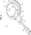
- Fig. 2 is a perspective view of the non-contact type balance head 20 and the stator 22.
- Fig.. 3 is an exploded perspective view of the balance head 20 and the stator 22 illustrated in Fig. 2 .
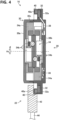
- Fig. 4 is a cross-sectional view of the balance head 20 and the stator 22 illustrated in Fig. 2 along a line 4-4.
- the balance head 20 includes: a case 30; a rotor part 32; a balance correction mechanism 34; an AE sensor 36; and a control board 38.
- the case 30 is formed in a hollow cylindrical shape which is parallel to the axial direction Ax.
- the case 30 includes: a front end surface 30a and a rear end surface 30b; and an outer peripheral surface 30c.
- the front end surface 30a and the rear end surface 30b are spaced apart from each other in the axial direction Ax, and respectively have a disk-shape perpendicular to the axial direction Ax.
- the outer peripheral surface 30c connects a peripheral part of the front end surface 30a and a peripheral part of the rear end surface 30b. Further, the outer peripheral surface 30c is formed so as to be dividable into two parts in the axial direction Ax.
- the electric balance correction mechanism 34 is housed inside the case 30.
- the control board 38 and the AE sensor 36 are provided inside a wall part forming the rear end surface 30b.
- the balance correction mechanism 34 includes: two balance weights 34a; and two sets of motor drive mechanisms 34b. Each of the balance weights 34a is held by a corresponding motor drive mechanism 34b so as to be displaceable (movable) in the circumferential direction ⁇ around the axial direction Ax. Each of the motor drive mechanisms 34b includes a motor and a plurality of gears, for example. Each of the motor drive mechanisms 34b receives energization from the control board 38 and moves each of the balance weights 34a independently from each other in the circumferential direction ⁇ . Note that the balance correction mechanism 34 should not be limited to the one shown in the drawings. Various types of known balance correction mechanisms may be applied.
- the AE sensor 36 is an acoustic emission sensor and corresponds to a detecting sensor of the present invention.
- the AE sensor 36 detects acoustic sound in highfrequency band generated when the grinding stone 12 comes into contact with, for example, the work to be machined W, a dresser, or other contacting objects, and outputs a detection signal of the acoustic sound to the control board 38.
- the rotor part 32 is provided on the outer peripheral surface 30c, and rotates integrally with the balance head 20 in the circumferential direction ⁇ .
- the rotor part 32 is formed into a shape which is along a circumferential direction (circumferential direction ⁇ around the axial direction Ax) of the outer peripheral surface 30c.
- the rotor part 32 is formed into a ring shape (flange shape).
- a rotor coil 32a which is a ring-shaped antenna coil, is provided inside the rotor part 32. Note that, although the rotor part 32 is formed integrally with the case 30 in the present embodiment, the rotor part 32 may be formed separately from the case 30 and fixed to the case 30.
- the rotor coil 32a is electrically connected to the control board 38. Further, the rotor coil 32a is electrically connected to the balance correction mechanism 34 and so on, via the control board 38.
- the rotor coil 32a receives drive power wirelessly transmitted (power transmission) from the stator 22 which is described later, and drive command of the balance correction mechanism 34 wirelessly transmitted (information transmission) also from the stator 22. Inversely, the rotor coil 32a wirelessly transmits (information transmission) the detection signal of the AE sensor 36 input from the control board 38, to the stator 22.
- the control board 38 includes: a processor such as a CPU (Central Processing Unit) and the like; a power receiving circuit; a power transmitting circuit; a reception demodulating part; a transmission modulating part; and so on.
- the control board 38 converts the drive power (alternative current power) received by the rotor coil 32a to direct current power, and then, supplies the drive power to the balance correction mechanism 34, the AE sensor 36 and so on. Further, the control board 38 outputs the drive command received by the rotor coil 32a, to the balance correction mechanism 34.
- the balance correction mechanism 34 controls energization to the rotor coil 32a so that the detection signal of the AE sensor 36 is wirelessly transmitted from the rotor coil 32a to the stator 22.
- the stator 22 is provided separately from the balance head 20.
- the stator 22 functions as a sender which wirelessly transmits the drive power and the drive command of the balance head 20 output from the controller 26.
- the stator 22 also functions as a receiver which receives the detection signal of the AE sensor 36 wirelessly transmitted from the rotor part 32 and outputs the detection signal to the controller 26.
- the stator 22 includes: a stator ring 40; a transmission/reception control part 42; and a signal cable 44.
- the stator ring 40 is formed in a ring shape which is along the circumferential direction of the outer peripheral surface 30c. Specifically, the stator ring 40 is formed to have an inner diameter larger than an outer diameter of the outer peripheral surface 30c, and is loosely fitted with the outer peripheral surface 30c (that is, the stator ring 40 is fitted on the outer peripheral surface 30c with a clearance from the outer peripheral surface 30c). In other words, the case 30 is inserted into a space surrounded by the stator ring 40.
- stator ring 40 is attached to a not-shown fixing part (for example, a machine guard) of the grinding machine 10 provided in a vicinity of the grinding stone 12, thereby fixing the stator ring 40 at a position where the stator ring 40 faces the rotor part 32 in the axial direction Ax, and is in a vicinity of the rotor part 32. Therefore, wireless transmission may be performed between the balance head 20 and the rotor part 32.
- a stator coil 40a which is a ring-shaped antenna coil, is provided inside the stator ring 40.
- the stator coil 40a performs wireless transmission of the drive power, the drive command, the detection signal and so on between the stator coil 40a and the rotor coil 32a, under control of the transmission/reception control part 42 which is described later.
- the transmission/reception control part 42 includes a transmission modulating part (transmitter), a reception demodulating part and so on.
- the transmission/reception control part 42 is electrically connected to the controller 26 via the signal cable 44, and also electrically connected to the stator coil 40a.
- the transmission/reception control part 42 controls energization to the stator coil 40a based on the drive power input from the controller 26, thereby wirelessly transmitting the drive power to the rotor coil 32a using a known system such as an electromagnetic induction system, a magnetic field resonance system, an electric field resonance system and so on. Further, the transmission/reception control part 42 controls energization to the stator coil 40a based on the drive command of the balance head 20 input from the controller 26, thereby wirelessly transmitting the drive command using a known system. Therefore, the drive power and the drive command may be transmitted from the stator 22 to the balance head 20 in a non-contact manner.
- a known system such as an electromagnetic induction system, a magnetic field resonance system, an electric field resonance system and so on.
- the transmission/reception control part 42 controls energization to the stator coil 40a based on the drive command of the balance head 20 input from the controller 26, thereby wirelessly transmitting the drive command using a known system. Therefore, the drive power and the drive
- the transmission/reception control part 42 outputs to the controller 26, the detection signal of the AE sensor 36 which is transmitted from the rotor coil 32a to the stator coil 40a in a non-contact manner.
- the vibration sensor 24 is attached to the spindle 14. Further, the vibration sensor 24 is connected to the controller 26 via a signal cable 50. The vibration sensor 24 detects low-frequency vibration emitted from the spindle 14 due to imbalance of the grinding stone 12 rotated at high speed by the spindle 14, and outputs the vibration detection signal to the controller 26.
- the controller 26 integrally controls supply of the drive power to the balance head 20, drive of the balance head 20 and vibration detection by the vibration sensor 24.
- the controller 26 While the rotation drive of the grinding stone 12 is performed by the spindle 14, the controller 26 outputs the drive power of the balance head 20 to the transmission/reception control part 42. While the drive power is input from the controller 26, the transmission/reception control part 42 controls energization to the stator coil 40a, and performs wireless transmission of the drive power from the stator coil 40a to the rotor coil 32a. The drive power received by the rotor coil 32a is supplied to respective parts of the balance head 20 via the control board 38. As a result, the balance head 20 and the AE sensor 36 are in an operating state.
- the AE sensor 36 starts detection of acoustic sound and continuously outputs a detection signal of the acoustic sound (acoustic sound detection signal) to the control board 38.
- the control board 38 controls energization to the rotor coil 32a based on the acoustic sound detection signal, thereby wirelessly transmitting the acoustic sound detection signal from the rotor coil 32a to the stator coil 40a.
- the acoustic sound detection signal received by the stator coil 40a is output to the controller 26 by the transmission/reception control part 42.
- the controller 26 may detect that the grinding stone 12 comes into contact with the work to be machined W based on the acoustic sound detection signal.
- the controller 26 causes the vibration sensor 24 to operate.
- a vibration detection signal is continuously input from the vibration sensor 24 to the controller 26.
- the controller 26 determines arrangement of the respective balance weights 34a in the balance correction mechanism 34 using a known method in such a manner that the arrangement may correct imbalance of the grinding stone 12.
- the controller 26 generates drive command for driving the balance correction mechanism 34 and outputs the drive command to the transmission/reception control part 42.
- the transmission/reception control part 42 controls energization to the stator coil 40a, and performs wireless transmission of the drive command from the stator coil 40a to the rotor coil 32a.
- the drive command received by the rotor coil 32a is input to the balance correction mechanism 34 via the control board 38.
- the balance correction mechanism 34 is driven according to the drive command so as to correct imbalance of the grinding stone 12 rotating at high speed.
- Fig. 5 is an explanatory diagram for explaining an advantageous effect of the automatic balancer 16 according to the present embodiment, compared to an automatic balancer 100 according to an comparative example.
- the automatic balancer 100 includes a balance head 102 and a stator 104, and a rotor 106 is provided on a front end surface of the balance head 102 via an adaptor 102a. Further, the stator 104 is arranged at a position facing the rotor 106. As a result, a length LA of the automatic balancer 100 becomes long because the balance head 102, the adaptor 102a, the rotor 106 and the stator 104 are arranged in series along the axial direction Ax.
- the automatic balancer 16 according to the present embodiment has a ring-shaped stator ring 40 in the stator 22, and the stator ring 40 is loosely fitted to the outer peripheral surface 30c of the balance head 20. Therefore, in the automatic balancer 16 according to the present embodiment, the rotor part 32 may be formed on the outer peripheral surface 30c, and the adaptor 102a in the comparative example becomes unnecessary. As a result, the length LB of whole of the automatic balancer 16 along the axial direction Ax becomes equal to a length of only the balance head 20 along the axial direction Ax.
- the length LB in the present embodiment becomes much shorter than the length LA in the comparative example along the axial direction Ax, thereby reducing a space for installing the automatic balancer 16 in the grinding machine 10.
- the outer peripheral surface 30c of the case 30 is formed in a circular cylindrical shape.
- the outer peripheral surface 30c may have any cylindrical shape other than a circular cylindrical shape.
- the rotor part 32 (rotor coil 32a) and the stator ring 40 (stator coil 40a) are respectively formed in a circular ring shape in the present embodiment, they may be formed in any shapes such as a rectangular ring shape (polygonal ring shape) and so on, as long as wireless transmission may be performed between the rotor coil 32a and the stator coil 40a.
- the rotor part 32 and the stator ring 40 are respectively formed in a ring shape.
- the shape of the rotor part 32 and the stator ring 40 is not limited to a ring shape as long as the shape of the rotor part 32 and the stator ring 40 is along the circumferential direction (circumferential direction ⁇ around the rotation axis) of the outer peripheral surface 30c.
- the rotor part 32 and the stator ring 40 may be formed in a circular arc shape or a semiring shape.
- either one of the rotor part 32 and the stator ring 40 is preferably formed in a ring shape in order to constantly perform wireless communication of the drive power and so on between the rotor part 32 and the stator ring 40.
- the rotor part 32 is provided at a position where the rotor part 32 faces the stator ring 40 in the axial direction Ax and is on the outer peripheral surface 30c.
- the position of the rotor part 32 is not limited to that position.
- the rotor part 32 may be provided at a position where the rotor part 32 faces an inner circumferential surface of the stator ring 40 and is on the outer peripheral surface 30c, that is, in a range surrounded by the stator ring 40 in the outer peripheral surface 30c.
- the present invention may be applied to an automatic balancer used for correcting imbalance of various types of rotating bodies provided in a semiconductor manufacturing apparatus other than the grinding machine 10. Further, the present invention may be applied in a case where imbalance of various types of rotating bodies in a technical field other than a semiconductor manufacturing apparatus.
Landscapes
- Physics & Mathematics (AREA)
- General Physics & Mathematics (AREA)
- Engineering & Computer Science (AREA)
- General Engineering & Computer Science (AREA)
- Acoustics & Sound (AREA)
- Aviation & Aerospace Engineering (AREA)
- Mechanical Engineering (AREA)
- Testing Of Balance (AREA)
- Manufacture Of Motors, Generators (AREA)
Applications Claiming Priority (2)
| Application Number | Priority Date | Filing Date | Title |
|---|---|---|---|
| US202263304971P | 2022-01-31 | 2022-01-31 | |
| PCT/JP2022/045623 WO2023145279A1 (ja) | 2022-01-31 | 2022-12-12 | オートバランサ |
Publications (2)
| Publication Number | Publication Date |
|---|---|
| EP4455628A1 true EP4455628A1 (de) | 2024-10-30 |
| EP4455628A4 EP4455628A4 (de) | 2025-04-09 |
Family
ID=87471567
Family Applications (1)
| Application Number | Title | Priority Date | Filing Date |
|---|---|---|---|
| EP22924130.2A Pending EP4455628A4 (de) | 2022-01-31 | 2022-12-12 | Automatische auswuchtvorrichtung |
Country Status (7)
| Country | Link |
|---|---|
| US (1) | US12281956B2 (de) |
| EP (1) | EP4455628A4 (de) |
| JP (1) | JP7573815B2 (de) |
| KR (1) | KR102839111B1 (de) |
| CN (1) | CN118633017B (de) |
| TW (1) | TW202404740A (de) |
| WO (1) | WO2023145279A1 (de) |
Families Citing this family (1)
| Publication number | Priority date | Publication date | Assignee | Title |
|---|---|---|---|---|
| PL449180A1 (pl) * | 2024-07-10 | 2025-02-03 | Aumatic Spółka Z Ograniczoną Odpowiedzialnością | Sposób wyważania wirującej części maszyny i urządzenie do wyważania wirującej części maszyny |
Family Cites Families (21)
| Publication number | Priority date | Publication date | Assignee | Title |
|---|---|---|---|---|
| US4899628A (en) * | 1988-06-13 | 1990-02-13 | Amca International Corporation | Dynamically compensating counterbalance |
| CN1038982A (zh) | 1989-06-03 | 1990-01-24 | 赵德军 | 利用液压机增大车辆运输力的方法 |
| JP2857419B2 (ja) * | 1989-06-16 | 1999-02-17 | 日立精工株式会社 | 回転体の動的バランサ |
| IT1263065B (it) * | 1993-03-22 | 1996-07-24 | Marposs Spa | Apparecchio per l'equilibratura dinamica di un corpo rotante. |
| US5757662A (en) * | 1994-11-29 | 1998-05-26 | Balance Dynamics, Inc. | Eletromagnetically actuated rotating machine unbalance compensator |
| JP4917197B2 (ja) | 2000-02-18 | 2012-04-18 | 株式会社岡本工作機械製作所 | 研削装置の回転軸のアンバランス補正方法 |
| WO2006017201A1 (en) * | 2004-07-12 | 2006-02-16 | Lord Corporation | Rotating machine active balancer and method of dynamically balancing a rotating machine shaft with torsional vibrations |
| ITBO20060489A1 (it) * | 2006-06-23 | 2007-12-24 | Marposs Spa | Sistema di controllo e dispositivo di equilibratura per macchina utensile con utensile rotante |
| JP4360394B2 (ja) * | 2006-10-24 | 2009-11-11 | ソニー株式会社 | 自動平衡装置、回転装置、ディスク駆動装置、バランサ |
| CN101158614B (zh) * | 2007-11-15 | 2010-04-07 | 中北大学 | 高速主轴在线动平衡装置 |
| IT1393813B1 (it) * | 2009-01-28 | 2012-05-11 | Balance Systems Srl | Gruppo di controllo per utensile |
| IT1392693B1 (it) * | 2009-01-28 | 2012-03-16 | Balance Systems Srl | Dispositivo equilibratore per corpi rotanti |
| JP2011095163A (ja) | 2009-10-30 | 2011-05-12 | Tokyo Seimitsu Co Ltd | オートバランサ |
| ES2798101T3 (es) * | 2012-10-02 | 2020-12-09 | Balance Systems Srl | Procedimiento y dispositivo de balanceo para un cuerpo rotatorio |
| JP2014074612A (ja) | 2012-10-03 | 2014-04-24 | Emitsuku Kk | 振動発生機 |
| EP2930489B1 (de) | 2014-04-09 | 2019-08-28 | Balance Systems S.r.L. | Auswuchtsystem und Auswuchtverfahren für ein drehbares Objekt |
| IT201900004703A1 (it) * | 2019-03-29 | 2020-09-29 | Marposs Spa | Sistema di equilibratura per un mandrino rotante di una macchina utensile e relativo metodo di controllo |
| CN110470428B (zh) * | 2019-09-09 | 2020-07-03 | 西安电子科技大学 | 一种形状记忆合金驱动的在线动平衡调整装置 |
| IT202000003521A1 (it) | 2020-02-20 | 2021-08-20 | Balance Systems Srl | Dispositivo di equilibratura per pezzi in rotazione |
| IT202000003524A1 (it) | 2020-02-20 | 2021-08-20 | Balance Systems Srl | Dispositivo equilibratore per pezzi in rotazione |
| US12208485B2 (en) * | 2020-06-03 | 2025-01-28 | Balance Systems S.R.L. | Balancing device for rotating pieces |
-
2022
- 2022-12-12 WO PCT/JP2022/045623 patent/WO2023145279A1/ja not_active Ceased
- 2022-12-12 CN CN202280090424.4A patent/CN118633017B/zh active Active
- 2022-12-12 KR KR1020247025378A patent/KR102839111B1/ko active Active
- 2022-12-12 EP EP22924130.2A patent/EP4455628A4/de active Pending
- 2022-12-12 JP JP2023576679A patent/JP7573815B2/ja active Active
-
2023
- 2023-01-09 TW TW112100824A patent/TW202404740A/zh unknown
-
2024
- 2024-07-30 US US18/789,239 patent/US12281956B2/en active Active
Also Published As
| Publication number | Publication date |
|---|---|
| KR102839111B1 (ko) | 2025-07-28 |
| JPWO2023145279A1 (de) | 2023-08-03 |
| WO2023145279A1 (ja) | 2023-08-03 |
| US12281956B2 (en) | 2025-04-22 |
| US20240385067A1 (en) | 2024-11-21 |
| CN118633017B (zh) | 2026-01-13 |
| JP7573815B2 (ja) | 2024-10-28 |
| CN118633017A (zh) | 2024-09-10 |
| KR20240123391A (ko) | 2024-08-13 |
| EP4455628A4 (de) | 2025-04-09 |
| TW202404740A (zh) | 2024-02-01 |
Similar Documents
| Publication | Publication Date | Title |
|---|---|---|
| US12281956B2 (en) | Automatic balancer | |
| EP0690979B1 (de) | Vorrichtung zum dynamischen auswuchten rotierender körper | |
| CN211958894U (zh) | 激光雷达及其旋转驱动组件 | |
| EP1187152B1 (de) | Kontaktloser Drehverbinder | |
| EP3134980B1 (de) | Vorrichtung und verfahren zum senden und empfangen alternierender optischer signale | |
| CN110880836B (zh) | 编码器的旋转部件的安装结构以及安装方法 | |
| KR101819103B1 (ko) | 자기기어 장치와, 이를 포함하는 동력전달 장치 및 그 제어방법 | |
| EP3852235A1 (de) | Kontaktlose stromversorgungs- und datenkommunikationsvorrichtung sowie system mit einer drehantriebseinheit damit | |
| EP3632626B1 (de) | Elektrowerkzeug | |
| EP3459681B1 (de) | Elektrisch betriebenes werkzeug | |
| EP1719579B1 (de) | Erfassungssignalübertragungsvorrichtung | |
| CN114127575B (zh) | 激光雷达 | |
| CN110773759B (zh) | 连接盘组件及具有其的数控车床电主轴 | |
| EP1914698A1 (de) | Detektionssignalsender | |
| JP2011095163A (ja) | オートバランサ | |
| CN113555987A (zh) | 激光雷达及其旋转驱动组件 | |
| JP3226307U (ja) | 知的予測機能を有する主軸 | |
| EP4341046B1 (de) | Elektrowerkzeug mit drahtlossignalübertragungsfähigkeit | |
| EP3772390B1 (de) | Schleifmaschinenwerkzeug mit zufälliger exzentrischer orbitaler bewegungsgeschwindigkeitserfassung | |
| US11758309B2 (en) | Antenna, telemetric device, and telemetric measurement system | |
| EP3632625B1 (de) | Elektrowerkzeug | |
| CN119339640A (zh) | 图像显示装置 | |
| WO2025205288A1 (ja) | 軸受装置および異常検知システム | |
| JPH09115085A (ja) | 信号伝送用の回転装置 |
Legal Events
| Date | Code | Title | Description |
|---|---|---|---|
| STAA | Information on the status of an ep patent application or granted ep patent |
Free format text: STATUS: THE INTERNATIONAL PUBLICATION HAS BEEN MADE |
|
| PUAI | Public reference made under article 153(3) epc to a published international application that has entered the european phase |
Free format text: ORIGINAL CODE: 0009012 |
|
| STAA | Information on the status of an ep patent application or granted ep patent |
Free format text: STATUS: REQUEST FOR EXAMINATION WAS MADE |
|
| 17P | Request for examination filed |
Effective date: 20240726 |
|
| AK | Designated contracting states |
Kind code of ref document: A1 Designated state(s): AL AT BE BG CH CY CZ DE DK EE ES FI FR GB GR HR HU IE IS IT LI LT LU LV MC ME MK MT NL NO PL PT RO RS SE SI SK SM TR |
|
| A4 | Supplementary search report drawn up and despatched |
Effective date: 20250310 |
|
| RIC1 | Information provided on ipc code assigned before grant |
Ipc: G01M 1/22 20060101ALI20250304BHEP Ipc: F16F 15/32 20060101ALI20250304BHEP Ipc: G01M 1/36 20060101AFI20250304BHEP |
|
| DAV | Request for validation of the european patent (deleted) | ||
| DAX | Request for extension of the european patent (deleted) | ||
| STAA | Information on the status of an ep patent application or granted ep patent |
Free format text: STATUS: EXAMINATION IS IN PROGRESS |
|
| 17Q | First examination report despatched |
Effective date: 20251119 |