EP4455595A1 - Plate heat exchanger - Google Patents
Plate heat exchanger Download PDFInfo
- Publication number
- EP4455595A1 EP4455595A1 EP22909612.8A EP22909612A EP4455595A1 EP 4455595 A1 EP4455595 A1 EP 4455595A1 EP 22909612 A EP22909612 A EP 22909612A EP 4455595 A1 EP4455595 A1 EP 4455595A1
- Authority
- EP
- European Patent Office
- Prior art keywords
- heat transfer
- protrusion
- plate
- transfer plate
- recess
- Prior art date
- Legal status (The legal status is an assumption and is not a legal conclusion. Google has not performed a legal analysis and makes no representation as to the accuracy of the status listed.)
- Pending
Links
Images






Classifications
-
- F—MECHANICAL ENGINEERING; LIGHTING; HEATING; WEAPONS; BLASTING
- F28—HEAT EXCHANGE IN GENERAL
- F28D—HEAT-EXCHANGE APPARATUS, NOT PROVIDED FOR IN ANOTHER SUBCLASS, IN WHICH THE HEAT-EXCHANGE MEDIA DO NOT COME INTO DIRECT CONTACT
- F28D9/00—Heat-exchange apparatus having stationary plate-like or laminated conduit assemblies for both heat-exchange media, the media being in contact with different sides of a conduit wall
-
- F—MECHANICAL ENGINEERING; LIGHTING; HEATING; WEAPONS; BLASTING
- F28—HEAT EXCHANGE IN GENERAL
- F28D—HEAT-EXCHANGE APPARATUS, NOT PROVIDED FOR IN ANOTHER SUBCLASS, IN WHICH THE HEAT-EXCHANGE MEDIA DO NOT COME INTO DIRECT CONTACT
- F28D9/00—Heat-exchange apparatus having stationary plate-like or laminated conduit assemblies for both heat-exchange media, the media being in contact with different sides of a conduit wall
- F28D9/0062—Heat-exchange apparatus having stationary plate-like or laminated conduit assemblies for both heat-exchange media, the media being in contact with different sides of a conduit wall the conduits for one heat-exchange medium being formed by spaced plates with inserted elements
-
- F—MECHANICAL ENGINEERING; LIGHTING; HEATING; WEAPONS; BLASTING
- F28—HEAT EXCHANGE IN GENERAL
- F28D—HEAT-EXCHANGE APPARATUS, NOT PROVIDED FOR IN ANOTHER SUBCLASS, IN WHICH THE HEAT-EXCHANGE MEDIA DO NOT COME INTO DIRECT CONTACT
- F28D9/00—Heat-exchange apparatus having stationary plate-like or laminated conduit assemblies for both heat-exchange media, the media being in contact with different sides of a conduit wall
- F28D9/0031—Heat-exchange apparatus having stationary plate-like or laminated conduit assemblies for both heat-exchange media, the media being in contact with different sides of a conduit wall the conduits for one heat-exchange medium being formed by paired plates touching each other
- F28D9/0043—Heat-exchange apparatus having stationary plate-like or laminated conduit assemblies for both heat-exchange media, the media being in contact with different sides of a conduit wall the conduits for one heat-exchange medium being formed by paired plates touching each other the plates having openings therein for circulation of at least one heat-exchange medium from one conduit to another
- F28D9/005—Heat-exchange apparatus having stationary plate-like or laminated conduit assemblies for both heat-exchange media, the media being in contact with different sides of a conduit wall the conduits for one heat-exchange medium being formed by paired plates touching each other the plates having openings therein for circulation of at least one heat-exchange medium from one conduit to another the plates having openings therein for both heat-exchange media
-
- F—MECHANICAL ENGINEERING; LIGHTING; HEATING; WEAPONS; BLASTING
- F28—HEAT EXCHANGE IN GENERAL
- F28F—DETAILS OF HEAT-EXCHANGE AND HEAT-TRANSFER APPARATUS, OF GENERAL APPLICATION
- F28F3/00—Plate-like or laminated elements; Assemblies of plate-like or laminated elements
- F28F3/02—Elements or assemblies thereof with means for increasing heat-transfer area, e.g. with fins, with recesses, with corrugations
- F28F3/04—Elements or assemblies thereof with means for increasing heat-transfer area, e.g. with fins, with recesses, with corrugations the means being integral with the element
- F28F3/042—Elements or assemblies thereof with means for increasing heat-transfer area, e.g. with fins, with recesses, with corrugations the means being integral with the element in the form of local deformations of the element
- F28F3/044—Elements or assemblies thereof with means for increasing heat-transfer area, e.g. with fins, with recesses, with corrugations the means being integral with the element in the form of local deformations of the element the deformations being pontual, e.g. dimples
-
- F—MECHANICAL ENGINEERING; LIGHTING; HEATING; WEAPONS; BLASTING
- F28—HEAT EXCHANGE IN GENERAL
- F28F—DETAILS OF HEAT-EXCHANGE AND HEAT-TRANSFER APPARATUS, OF GENERAL APPLICATION
- F28F3/00—Plate-like or laminated elements; Assemblies of plate-like or laminated elements
- F28F3/08—Elements constructed for building-up into stacks, e.g. capable of being taken apart for cleaning
-
- F—MECHANICAL ENGINEERING; LIGHTING; HEATING; WEAPONS; BLASTING
- F28—HEAT EXCHANGE IN GENERAL
- F28F—DETAILS OF HEAT-EXCHANGE AND HEAT-TRANSFER APPARATUS, OF GENERAL APPLICATION
- F28F2225/00—Reinforcing means
- F28F2225/04—Reinforcing means for conduits
-
- F—MECHANICAL ENGINEERING; LIGHTING; HEATING; WEAPONS; BLASTING
- F28—HEAT EXCHANGE IN GENERAL
- F28F—DETAILS OF HEAT-EXCHANGE AND HEAT-TRANSFER APPARATUS, OF GENERAL APPLICATION
- F28F2275/00—Fastening; Joining
- F28F2275/04—Fastening; Joining by brazing
-
- F—MECHANICAL ENGINEERING; LIGHTING; HEATING; WEAPONS; BLASTING
- F28—HEAT EXCHANGE IN GENERAL
- F28F—DETAILS OF HEAT-EXCHANGE AND HEAT-TRANSFER APPARATUS, OF GENERAL APPLICATION
- F28F2275/00—Fastening; Joining
- F28F2275/06—Fastening; Joining by welding
Definitions
- the embodiments of the present invention relate to a plate heat exchanger.
- An objective of an embodiment of the present invention is to provide a plate heat exchanger, whereby the welding quality of a heat exchanger is improved.
- a plate heat exchanger including a plurality of heat transfer plates.
- the plurality of heat transfer plates include: a first heat transfer plate including a protrusion protruding upward, the protrusion having a top; and a second heat transfer plate stacked on the first heat transfer plate and including a recess sunken downward, the recess having a bottom, wherein the top of the protrusion has a concave portion sunken downward, and at least a part of the bottom of the recess of the second heat transfer plate is located in the concave portion at the top of the protrusion of the first heat transfer plate.
- the concave portion at the top of the protrusion is located in the middle of the top.
- the concave portion at the top of the protrusion is located on one side of the top, and the top of the protrusion is step-shaped.
- the concave portion at the top of the protrusion has an upward flat bottom surface.
- the bottom of the recess has a downward curved bottom surface or downward flat bottom surface.
- a portion at the top of the protrusion other than the concave portion has at least one of a curved top surface portion and a flat top surface portion.
- the bottom of the recess has a concave portion sunken upward.
- the concave portion at the bottom of the recess is located in the middle of the bottom.
- a bottom portion of the concave portion at the top of the protrusion has an upward convex portion, and at least a part of the convex portion of the bottom portion of the concave portion at the top of the protrusion is located in the concave portion at the bottom of the recess.
- the bottom of the recess has a convex portion protruding downward, and at least a part of the convex portion at the bottom of the recess is located in the concave portion at the top of the protrusion.
- the concave portion at the top of the protrusion is located on one side of the top, and the top of the protrusion is step-shaped; and the convex portion at the bottom of the recess is located on one side of the bottom of the recess, and the bottom of the recess is step-shaped.
- the top of the protrusion and the bottom of the recess have complementary shapes.
- the protrusion of the first heat transfer plate and the recess of the second heat transfer plate are located in at least a part of a heat exchange zone and/or at least a part of an opening zone of the plate heat exchanger.
- the first heat transfer plate further includes a recess sunken downward
- the second heat transfer plate further includes a protrusion protruding upward.
- the plurality of heat transfer plates include a plurality of first heat transfer plates and a plurality of second heat transfer plates, which are stacked on top of each other, the plurality of first heat transfer plates and the plurality of second heat transfer plates being alternately arranged, and the bottom of the recess of one of every two adjacent heat transfer plates being connected to the top of the protrusion of the other of the two adjacent heat transfer plates.
- the top of the protrusion of the second heat transfer plate has a concave portion sunken downward, and at least a part of the bottom of the recess of the first heat transfer plate is located in the concave portion at the top of the protrusion of the second heat transfer plate.
- the concave portion at the top of the protrusion of the first heat transfer plate and the bottom of the recess of the second heat transfer plate are circular when viewed in the stacking direction of the first heat transfer plate and the second heat transfer plate, or the concave portion at the top of the protrusion of the first heat transfer plate and the bottom of the recess of the second heat transfer plate are crescent-shaped when viewed in the stacking direction of the first heat transfer plate and the second heat transfer plate.
- the concave portion at the top of the protrusion of the first heat transfer plate is circular when viewed in the stacking direction of the first heat transfer plate and the second heat transfer plate, and the concave portion at the top of the protrusion of the second heat transfer plate is crescent-shaped when viewed in the stacking direction of the first heat transfer plate and the second heat transfer plate.
- the angle of inclination of at least a part of a side wall of the concave portion at the top of the protrusion of the first heat transfer plate with respect to a horizontal plane is greater than or equal to the angle of inclination of a corresponding portion of a side wall of the recess of the second heat transfer plate with respect to the horizontal plane.
- the angle of inclination of at least a part of a side wall of the concave portion at the top of the protrusion of the first heat transfer plate with respect to a horizontal plane is greater than or equal to the angle of inclination of a corresponding portion of a side wall of the convex portion at the bottom of the recess of the second heat transfer plate with respect to the horizontal plane.
- the welding quality is improved.
- a plate heat exchanger 100 includes a plurality of heat transfer plates 10; heat exchange spaces formed between the adjacent heat transfer plates 10 of the plurality of heat transfer plates 10; and channels formed in the heat transfer plates 10. Openings 11 of the plurality of heat transfer plates 10 constitute the channels.
- the channels are configured for a heat exchange medium (for example, a refrigerant) to flow into or out of the heat exchanger 100.
- the heat transfer plate 10 or the heat exchanger 100 includes a heat exchange zone 21 for heat exchange of the heat exchange medium and an opening zone 22 surrounding the opening.
- the plurality of heat transfer plates 10 include: a first heat transfer plate 10A, the first heat transfer plate 10A including a protrusion 5 protruding upward, and the protrusion 5 having a top 51; and a second heat transfer plate 10B stacked on the first heat transfer plate 10A, the second heat transfer plate 10B including a recess 6 sunken downward, and the recess 6 having a bottom 61.
- the top 51 of the protrusion 5 has a concave portion 52 sunken downward, and at least a part of the bottom 61 of the recess 6 of the second heat transfer plate 10B is located in the concave portion 52 at the top 51 of the protrusion 5 of the first heat transfer plate 10A.
- the protrusion 5 of the first heat transfer plate 10A and the recess 6 of the second heat transfer plate 10B are located in at least a part of the heat exchange zone 21 of the plate heat exchanger 100.
- the protrusion 5 of the first heat transfer plate 10A and the recess 6 of the second heat transfer plate 10B may also be located in at least a part of the opening zone 22 of the plate heat exchanger 100. That is, the concept of the present invention may also be applied to the opening zone 22 of the plate heat exchanger 100.
- the first heat transfer plate 10A further includes the recess 6 sunken downward
- the second heat transfer plate 10B further includes the protrusion 5 protruding upward or a protrusion 5 protruding upward (free from the concave portion, see FIG. 14 ).
- the plurality of heat transfer plates 10 include a plurality of first heat transfer plates 10A and a plurality of second heat transfer plates 10B, which are stacked on top of each other, the plurality of first heat transfer plates 10A and the plurality of second heat transfer plates 10B being alternately arranged.
- each heat transfer plate 10 has the protrusion 5 protruding upward and the recess 6 sunken downward
- the top of the protrusion 5 of one of every two adjacent heat transfer plates 10 is connected to the bottom of the recess 6 of the other of the two adjacent heat transfer plates 10
- each heat transfer plate 10 other than the outermost heat transfer plate of the heat exchanger is stacked between two heat transfer plates 10.
- the top 51 of the protrusion 5 of the second heat transfer plate 10B has the concave portion 52 sunken downward, and at least a part of the bottom 61 of the recess 6 of the first heat transfer plate 10A is located in the concave portion 52 at the top 51 of the protrusion 5 of the second heat transfer plate 10B.
- the concave portion 52 at the top 51 of the protrusion 5 is located in the middle of the top 51.
- the top 51 is in a symmetrical shape with respect to one or more vertical planes passing through the center of the top 51 on a horizontal plane, or the top 51 is in a rotationally symmetrical shape with respect to a vertical straight line passing through the center of the top 51 on a horizontal plane.
- the bottom 61 is in a symmetrical shape with respect to one or more vertical planes passing through the center of the bottom 61 on a horizontal plane, or the bottom 61 is in a rotationally symmetrical shape with respect to a vertical straight line passing through the center of the bottom 61 on a horizontal plane.
- the concave portion 52 at the top 51 of the protrusion 5 is located on one side of the top 51, and the top 51 of the protrusion 5 is step-shaped.
- the concave portion 52 at the top 51 of the protrusion 5 has an upward flat bottom surface 53.
- the bottom 61 of the recess 6 has a downward curved bottom surface 63 or a downward flat bottom surface 63.
- a portion 54 at the top 51 of the protrusion 5 other than the concave portion 52 has at least one of a curved top surface portion 55 and a flat top surface portion 55.
- the concave portion 52 at the top 51 of the protrusion 5 has an upward flat bottom surface 53
- the bottom 61 of the recess 6 has a downward flat bottom surface 63.
- the bottom 61 of the recess 6 has a concave portion 62 sunken upward.
- the concave portion 62 at the bottom 61 of the recess 6 may be located in the middle of the bottom 61.
- the bottom 61 is in a symmetrical shape with respect to one or more vertical planes passing through the center of the bottom 61 on a horizontal plane, or the bottom 61 is in a rotationally symmetrical shape with respect to a vertical straight line passing through the center of the bottom 61 on a horizontal plane.
- a bottom portion 56 of the concave portion 52 at the top 51 of the protrusion 5 has an upward convex portion 57, and at least a part of the convex portion 57 of the bottom portion 56 of the concave portion 52 at the top 51 of the protrusion 5 is located in the concave portion 62 at the bottom 61 of the recess 6.
- the bottom 61 of the recess 6 has a convex portion 64 protruding downward, and at least a part of the convex portion 64 at the bottom 61 of the recess 6 is located in the concave portion 52 at the top 51 of the protrusion 5.
- the concave portion 52 at the top 51 of the protrusion 5 is located on one side of the top 51, and the top 51 of the protrusion 5 is step-shaped; and the convex portion 64 at the bottom 61 of the recess 6 is located on one side of the bottom 61 of the recess 6, and the bottom 61 of the recess 6 is step-shaped.
- the top 51 of the protrusion 5 and the bottom 61 of the recess 6 have complementary shapes.
- a top surface of the top 51 of the protrusion 5 and a bottom surface of the bottom 61 of the recess 6 have complementary shapes.
- the angle of inclination of at least a part of a side wall 58 of the concave portion 52 at the top 51 of the protrusion 5 of the first heat transfer plate 10A with respect to a horizontal plane is greater than or equal to the angle of inclination of a corresponding portion of a side wall 68 of the recess 6 of the second heat transfer plate 10B with respect to the horizontal plane.
- the corresponding portion of the side wall 68 corresponds to the at least a part of the side wall 58.
- the angle of inclination of at least a part of the side wall 58 of the concave portion 52 at the top 51 of the protrusion 5 of the first heat transfer plate 10A with respect to the horizontal plane is greater than or equal to the angle of inclination of a corresponding portion of a side wall 69 of the convex portion 64 at the bottom 61 of the recess 6 of the second heat transfer plate 10B with respect to the horizontal plane.
- the corresponding portion of the side wall 69 corresponds to the at least a part of the side wall 58.
- the heat transfer plate separates two different channels.
- all the heat transfer plates 10 may only have the protrusions 5 and the recesses 6 according to the embodiments of the present invention, or as shown in FIG. 14 , some heat transfer plates 10 may have traditional protrusions 5 and recesses 6, and another heat transfer plate 10 may have the protrusion 5 and the recess 6 according to the embodiments of the present invention. Therefore, an appropriate symmetry ratio of the channels, and an appropriate design of the protrusion 5 and the recess 6 are selected according to the actually desired welding strength and performance requirements with reference to the complexity of design and process.
- the protrusions 5 and the recesses 6 of the first heat transfer plate 10A and the second heat transfer plate 10B are alternately arranged in a first direction and alternately arranged in a second direction intersecting the first direction.
- the concave portion 52 at the top 51 of the protrusion 5 of the first heat transfer plate 10A is circular or crescent-shaped when viewed in the stacking direction of the first heat transfer plate 10A and the second heat transfer plate 10B.
- the circular protrusion 5 of one of every two adjacent heat transfer plates 10 is connected to the circular recess 6 of the other of the two adjacent heat transfer plates 10, and the crescent-shaped recess 6 of one of every two adjacent heat transfer plates 10 is connected to the crescent-shaped protrusion 5 of the other of the two adjacent heat transfer plates 10.
- the protrusion 5 and the recess 6 of the first heat transfer plate 10A, and the protrusion 5 and the recess 6 of the second heat transfer plate 10B are circular when viewed in the stacking direction of the first heat transfer plate 10A and the second heat transfer plate 10B.
- the concave portion 52 at the top 51 of the protrusion 5 of the first heat transfer plate 10A and the concave portion 52 at the top 51 of the protrusion 5 of the second heat transfer plate 10B are circular when viewed in the stacking direction of the first heat transfer plate 10A and the second heat transfer plate 10B. According to another example of the present invention, referring to FIGS.
- the protrusion 5 of the first heat transfer plate 10A and the recess 6 of the second heat transfer plate 10B are circular when viewed in the stacking direction of the first heat transfer plate 10A and the second heat transfer plate 10B, and the recess 6 of the first heat transfer plate 10A and the protrusion 5 of the second heat transfer plate 10B are crescent-shaped when viewed in the stacking direction of the first heat transfer plate 10A and the second heat transfer plate 10B.
- the concave portion 52 at the top 51 of the protrusion 5 of the first heat transfer plate 10A and the bottom of the recess 6 of the second heat transfer plate 19B are circular when viewed in the stacking direction of the first heat transfer plate 10A and the second heat transfer plate 10B, and the bottom of the recess 6 of the first heat transfer plate 10A and the concave portion 52 at the top 51 of the protrusion 5 of the second heat transfer plate 10B are crescent-shaped when viewed in the stacking direction of the first heat transfer plate 10A and the second heat transfer plate 10B.
- the concave portion 52 at the top 51 of the protrusion 5 may also be in any other appropriate shapes. That is, the shape of the concave portion at the top 51 of the protrusion 5 may be consistent with that of the protrusion 5, and the shape of the bottom 61 of the recess 6 may be consistent with that of the recess 6, thus facilitating processing.
- At least a part of the bottom 61 of the recess 6 of the second heat transfer plate 10B is located in the concave portion 52 at the top 51 of the protrusion 5 of the first heat transfer plate 10A. That is, the concave portion 52 at least partially surrounds the bottom 61. Therefore, the butt welding of the top of the protrusion of one of two adjacent heat transfer plates to the bottom of the corresponding recess of the other heat transfer plate is changed into a combination of butt welding and overlap welding.
- the bottom 61 of the recess 6 of the second heat transfer plate 10B is locked to the top 51 of the protrusion 5 of the first heat transfer plate 10A, so that the top 51 of the protrusion 5 of the first heat transfer plate 10A is kept facing the bottom 61 of the recess 6 of the second heat transfer plate 10B, thereby positioning the heat transfer plates in the technological process, increasing the welding area, and hence making the welding firmer.
- FIGS. 4 and 5 in case of a flatness defect and a molding problem, there is a gap ⁇ H between the bottoms 61 of some recesses 6 and bottom portions 56 of the concave portions 52 at the tops 51 of the corresponding protrusions 5.
- a gap C between the side wall 58 and the side wall 68 is smaller than the gap ⁇ H between the bottoms 61 of the recesses 6 and the bottom portions 56 of the concave portions 52, which can offset the effects caused by the problems of flatness and molding of the heat transfer plates. Due to the concave portion 52 at the top 51 of the protrusion 5, more solder can be reserved for soldering, and solder paste can be used as the solder to reduce the cost.
- the bottom 61 of the recess 6 and the bottom portion 56 of the concave portion 52 at the top 51 of the corresponding protrusion 5 may be curved surfaces or planes, and may be of symmetric structures or asymmetric structures. This reduces the requirements on the molding accuracy of the heat transfer plates while ensuring positioning and increasing the welding area, and may increase the possibility of adjusting the symmetry rate of the channels on two sides of the heat transfer plates. Therefore, the purpose of performance optimization is achieved.
- the bottom 61 of the recess 6 has the concave portion 62 sunken upward, and referring to FIG. 9 , the bottom 61 of the recess 6 has the convex portion 64 protruding downward. Therefore, the welding area can be increased to a greater extent, the solder can be better preserved, and the possibility of adjusting the symmetry ratio of the channels on two sides of the heat transfer plates can be increased.
- the concave portion 52 at the top 51 of the protrusion 5 is located on one side of the top 51, and the top 51 of the protrusion 5 is step-shaped; and the convex portion 64 at the bottom 61 of the recess 6 is located on one side of the bottom 61 of the recess 6, and the bottom 61 of the recess 6 is step-shaped.
- the bottom 61 of the recess 6 has the concave portion 62 sunken upward and the bottom portion 56 of the concave portion 52 at the top 51 of the protrusion 5 has the upward convex portion 57. That is, both of the bottom 61 of the recess 6 and the top 51 of the protrusion 5 have grooves or bulges.
- the welding quality and the heat exchange performance of the heat exchanger can be improved, and the process difficulty can be reduced.
Landscapes
- Engineering & Computer Science (AREA)
- Physics & Mathematics (AREA)
- Thermal Sciences (AREA)
- Mechanical Engineering (AREA)
- General Engineering & Computer Science (AREA)
- Heat-Exchange Devices With Radiators And Conduit Assemblies (AREA)
Abstract
Description
- The embodiments of the present invention relate to a plate heat exchanger.
- In a traditional plate heat exchanger, the top of a protrusion of one of two adjacent heat transfer plates is butt-welded to the bottom of a corresponding recess of the other heat transfer plate. Therefore, a flow path can be formed in a heat exchange zone of the plate heat exchanger.
- An objective of an embodiment of the present invention is to provide a plate heat exchanger, whereby the welding quality of a heat exchanger is improved.
- According to an embodiment of the present invention, a plate heat exchanger is provided, including a plurality of heat transfer plates. The plurality of heat transfer plates include: a first heat transfer plate including a protrusion protruding upward, the protrusion having a top; and a second heat transfer plate stacked on the first heat transfer plate and including a recess sunken downward, the recess having a bottom, wherein the top of the protrusion has a concave portion sunken downward, and at least a part of the bottom of the recess of the second heat transfer plate is located in the concave portion at the top of the protrusion of the first heat transfer plate.
- According to an embodiment of the present invention, the concave portion at the top of the protrusion is located in the middle of the top.
- According to an embodiment of the present invention, the concave portion at the top of the protrusion is located on one side of the top, and the top of the protrusion is step-shaped.
- According to an embodiment of the present invention, the concave portion at the top of the protrusion has an upward flat bottom surface.
- According to an embodiment of the present invention, the bottom of the recess has a downward curved bottom surface or downward flat bottom surface.
- According to an embodiment of the present invention, a portion at the top of the protrusion other than the concave portion has at least one of a curved top surface portion and a flat top surface portion.
- According to an embodiment of the present invention, the bottom of the recess has a concave portion sunken upward.
- According to an embodiment of the present invention, the concave portion at the bottom of the recess is located in the middle of the bottom.
- According to an embodiment of the present invention, a bottom portion of the concave portion at the top of the protrusion has an upward convex portion, and at least a part of the convex portion of the bottom portion of the concave portion at the top of the protrusion is located in the concave portion at the bottom of the recess.
- According to an embodiment of the present invention, the bottom of the recess has a convex portion protruding downward, and at least a part of the convex portion at the bottom of the recess is located in the concave portion at the top of the protrusion.
- According to an embodiment of the present invention, the concave portion at the top of the protrusion is located on one side of the top, and the top of the protrusion is step-shaped; and the convex portion at the bottom of the recess is located on one side of the bottom of the recess, and the bottom of the recess is step-shaped.
- According to an embodiment of the present invention, the top of the protrusion and the bottom of the recess have complementary shapes.
- According to an embodiment of the present invention, the protrusion of the first heat transfer plate and the recess of the second heat transfer plate are located in at least a part of a heat exchange zone and/or at least a part of an opening zone of the plate heat exchanger.
- According to an embodiment of the present invention, the first heat transfer plate further includes a recess sunken downward, and the second heat transfer plate further includes a protrusion protruding upward.
- According to an embodiment of the present invention, the plurality of heat transfer plates include a plurality of first heat transfer plates and a plurality of second heat transfer plates, which are stacked on top of each other, the plurality of first heat transfer plates and the plurality of second heat transfer plates being alternately arranged, and the bottom of the recess of one of every two adjacent heat transfer plates being connected to the top of the protrusion of the other of the two adjacent heat transfer plates.
- According to an embodiment of the present invention, the top of the protrusion of the second heat transfer plate has a concave portion sunken downward, and at least a part of the bottom of the recess of the first heat transfer plate is located in the concave portion at the top of the protrusion of the second heat transfer plate.
- According to an embodiment of the present invention, the concave portion at the top of the protrusion of the first heat transfer plate and the bottom of the recess of the second heat transfer plate are circular when viewed in the stacking direction of the first heat transfer plate and the second heat transfer plate, or the concave portion at the top of the protrusion of the first heat transfer plate and the bottom of the recess of the second heat transfer plate are crescent-shaped when viewed in the stacking direction of the first heat transfer plate and the second heat transfer plate.
- According to an embodiment of the present invention, the concave portion at the top of the protrusion of the first heat transfer plate is circular when viewed in the stacking direction of the first heat transfer plate and the second heat transfer plate, and the concave portion at the top of the protrusion of the second heat transfer plate is crescent-shaped when viewed in the stacking direction of the first heat transfer plate and the second heat transfer plate.
- According to an embodiment of the present invention, the angle of inclination of at least a part of a side wall of the concave portion at the top of the protrusion of the first heat transfer plate with respect to a horizontal plane is greater than or equal to the angle of inclination of a corresponding portion of a side wall of the recess of the second heat transfer plate with respect to the horizontal plane.
- According to an embodiment of the present invention, the angle of inclination of at least a part of a side wall of the concave portion at the top of the protrusion of the first heat transfer plate with respect to a horizontal plane is greater than or equal to the angle of inclination of a corresponding portion of a side wall of the convex portion at the bottom of the recess of the second heat transfer plate with respect to the horizontal plane.
- In the plate heat exchanger according to the embodiments of the present invention, since at least a part of the bottom of the recess of the second heat transfer plate is located in the concave portion at the top of the protrusion of the first heat transfer plate, the welding quality is improved.
-
-
FIG. 1 is a schematic perspective view of a plate heat exchanger according to an embodiment of the present invention; -
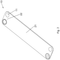
FIG. 2 is a schematic perspective view of a heat transfer plate of the plate heat exchanger shown inFIG. 1 ; -
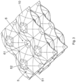
FIG. 3 is a schematic enlarged view of a portion, located in a heat exchange zone, of the heat transfer plate of the plate heat exchanger shown inFIG. 1 ; -
FIG. 4 is a schematic diagram of portions of two adjacent heat transfer plates of a plate heat exchanger according to an embodiment of the present invention; -
FIG. 5 is a schematic diagram of portions of two adjacent heat transfer plates of a plate heat exchanger according to another embodiment of the present invention; -
FIG. 6 is a schematic diagram of protrusions and recesses of two adjacent heat transfer plates of a plate heat exchanger according to a variant of an embodiment of the present invention; -
FIG. 7 is a schematic diagram of protrusions and recesses of two adjacent heat transfer plates of a plate heat exchanger according to another variant of an embodiment of the present invention; -
FIG. 8 is a schematic diagram of protrusions and recesses of two adjacent heat transfer plates of a plate heat exchanger according to yet another variant of an embodiment of the present invention; -
FIG. 9 is a schematic diagram of protrusions and recesses of two adjacent heat transfer plates of a plate heat exchanger according to still yet another variant of an embodiment of the present invention; -
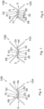
FIG. 10 is a schematic diagram of protrusions and recesses of two adjacent heat transfer plates of a plate heat exchanger according to a further variant of an embodiment of the present invention; -
FIG. 11 is a schematic diagram of protrusions and recesses of two adjacent heat transfer plates of a plate heat exchanger according to a further variant of an embodiment of the present invention; -
FIG. 12 is a schematic diagram of protrusions and recesses of two adjacent heat transfer plates of a plate heat exchanger according to a further variant of an embodiment of the present invention; -
FIG. 13 is a schematic front view of a portion of a heat transfer plate of a plate heat exchanger according to a variant of an embodiment of the present invention; -
FIG. 14 is a schematic front view of a portion of a heat transfer plate of a plate heat exchanger according to another variant of an embodiment of the present invention; -
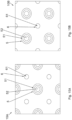
FIGS. 15A and 15B are respectively views of portions of two adjacent heat transfer plates of a plate heat exchanger according to an embodiment of the present invention, showing patterns at tops of protrusions and at bottoms of recesses; and -
FIGS. 16A and 16B are respectively views of portions of two adjacent heat transfer plates of a plate heat exchanger according to another embodiment of the present invention, showing patterns at tops of protrusions and at bottoms of recesses. - The present invention will be described below in further detail in conjunction with the drawings and specific embodiments.
- As shown in
FIGS. 1 to 16B , aplate heat exchanger 100 according to an embodiment of the present invention includes a plurality ofheat transfer plates 10; heat exchange spaces formed between the adjacentheat transfer plates 10 of the plurality ofheat transfer plates 10; and channels formed in theheat transfer plates 10.Openings 11 of the plurality ofheat transfer plates 10 constitute the channels. The channels are configured for a heat exchange medium (for example, a refrigerant) to flow into or out of theheat exchanger 100. Theheat transfer plate 10 or theheat exchanger 100 includes aheat exchange zone 21 for heat exchange of the heat exchange medium and anopening zone 22 surrounding the opening. - As shown in
FIGS. 1 to 16B , the plurality ofheat transfer plates 10 include: a firstheat transfer plate 10A, the firstheat transfer plate 10A including aprotrusion 5 protruding upward, and theprotrusion 5 having atop 51; and a secondheat transfer plate 10B stacked on the firstheat transfer plate 10A, the secondheat transfer plate 10B including arecess 6 sunken downward, and therecess 6 having abottom 61. Thetop 51 of theprotrusion 5 has aconcave portion 52 sunken downward, and at least a part of thebottom 61 of therecess 6 of the secondheat transfer plate 10B is located in theconcave portion 52 at thetop 51 of theprotrusion 5 of the firstheat transfer plate 10A. Theprotrusion 5 of the firstheat transfer plate 10A and therecess 6 of the secondheat transfer plate 10B are located in at least a part of theheat exchange zone 21 of theplate heat exchanger 100. Of course, theprotrusion 5 of the firstheat transfer plate 10A and therecess 6 of the secondheat transfer plate 10B may also be located in at least a part of theopening zone 22 of theplate heat exchanger 100. That is, the concept of the present invention may also be applied to theopening zone 22 of theplate heat exchanger 100. - As shown in
FIGS. 3 to 16B , in an embodiment of the present invention, the firstheat transfer plate 10A further includes therecess 6 sunken downward, and the secondheat transfer plate 10B further includes theprotrusion 5 protruding upward or aprotrusion 5 protruding upward (free from the concave portion, seeFIG. 14 ). The plurality ofheat transfer plates 10 include a plurality of firstheat transfer plates 10A and a plurality of secondheat transfer plates 10B, which are stacked on top of each other, the plurality of firstheat transfer plates 10A and the plurality of secondheat transfer plates 10B being alternately arranged. That is, eachheat transfer plate 10 has theprotrusion 5 protruding upward and therecess 6 sunken downward, the top of theprotrusion 5 of one of every two adjacentheat transfer plates 10 is connected to the bottom of therecess 6 of the other of the two adjacentheat transfer plates 10, and eachheat transfer plate 10 other than the outermost heat transfer plate of the heat exchanger is stacked between twoheat transfer plates 10. For example, thetop 51 of theprotrusion 5 of the secondheat transfer plate 10B has theconcave portion 52 sunken downward, and at least a part of thebottom 61 of therecess 6 of the firstheat transfer plate 10A is located in theconcave portion 52 at thetop 51 of theprotrusion 5 of the secondheat transfer plate 10B. - As shown in
FIGS. 4-6 ,9 and12-14 , in an embodiment of the present invention, theconcave portion 52 at thetop 51 of theprotrusion 5 is located in the middle of thetop 51. For example, thetop 51 is in a symmetrical shape with respect to one or more vertical planes passing through the center of thetop 51 on a horizontal plane, or thetop 51 is in a rotationally symmetrical shape with respect to a vertical straight line passing through the center of thetop 51 on a horizontal plane. Accordingly, as an example, the bottom 61 is in a symmetrical shape with respect to one or more vertical planes passing through the center of the bottom 61 on a horizontal plane, or the bottom 61 is in a rotationally symmetrical shape with respect to a vertical straight line passing through the center of the bottom 61 on a horizontal plane. - As shown in
FIGS. 8 and11 , in an embodiment of the present invention, theconcave portion 52 at the top 51 of theprotrusion 5 is located on one side of the top 51, and the top 51 of theprotrusion 5 is step-shaped. - In an embodiment of the present invention, as shown in
FIGS. 4-11 , theconcave portion 52 at the top 51 of theprotrusion 5 has an upwardflat bottom surface 53. As shown inFIGS. 4-12 , the bottom 61 of therecess 6 has a downwardcurved bottom surface 63 or a downwardflat bottom surface 63. As shown inFIGS. 4-12 , aportion 54 at the top 51 of theprotrusion 5 other than theconcave portion 52 has at least one of a curvedtop surface portion 55 and a flattop surface portion 55. As shown inFIGS. 4 ,5 ,8 ,9 and11 , theconcave portion 52 at the top 51 of theprotrusion 5 has an upwardflat bottom surface 53, and the bottom 61 of therecess 6 has a downwardflat bottom surface 63. - As shown in
FIGS. 10 and12 , in an embodiment of the present invention, the bottom 61 of therecess 6 has aconcave portion 62 sunken upward. Theconcave portion 62 at the bottom 61 of therecess 6 may be located in the middle of the bottom 61. For example, the bottom 61 is in a symmetrical shape with respect to one or more vertical planes passing through the center of the bottom 61 on a horizontal plane, or the bottom 61 is in a rotationally symmetrical shape with respect to a vertical straight line passing through the center of the bottom 61 on a horizontal plane. In an example of the present invention, as shown inFIG. 12 , abottom portion 56 of theconcave portion 52 at the top 51 of theprotrusion 5 has an upwardconvex portion 57, and at least a part of theconvex portion 57 of thebottom portion 56 of theconcave portion 52 at the top 51 of theprotrusion 5 is located in theconcave portion 62 at the bottom 61 of therecess 6. - As shown in
FIGS. 9 and11 , in an embodiment of the present invention, the bottom 61 of therecess 6 has aconvex portion 64 protruding downward, and at least a part of theconvex portion 64 at the bottom 61 of therecess 6 is located in theconcave portion 52 at the top 51 of theprotrusion 5. In an embodiment as shown inFIG. 11 , theconcave portion 52 at the top 51 of theprotrusion 5 is located on one side of the top 51, and the top 51 of theprotrusion 5 is step-shaped; and theconvex portion 64 at the bottom 61 of therecess 6 is located on one side of the bottom 61 of therecess 6, and the bottom 61 of therecess 6 is step-shaped. - As shown in
FIGS. 9 ,11 and 12 , in an embodiment of the present invention, the top 51 of theprotrusion 5 and the bottom 61 of therecess 6 have complementary shapes. In other words, a top surface of the top 51 of theprotrusion 5 and a bottom surface of the bottom 61 of therecess 6 have complementary shapes. - As shown in
FIGS. 4-8 ,10 and12 , in an embodiment of the present invention, the angle of inclination of at least a part of aside wall 58 of theconcave portion 52 at the top 51 of theprotrusion 5 of the firstheat transfer plate 10A with respect to a horizontal plane is greater than or equal to the angle of inclination of a corresponding portion of aside wall 68 of therecess 6 of the secondheat transfer plate 10B with respect to the horizontal plane. The corresponding portion of theside wall 68 corresponds to the at least a part of theside wall 58. - As shown in
FIGS. 9 and11 , in an embodiment of the present invention, the angle of inclination of at least a part of theside wall 58 of theconcave portion 52 at the top 51 of theprotrusion 5 of the firstheat transfer plate 10A with respect to the horizontal plane is greater than or equal to the angle of inclination of a corresponding portion of aside wall 69 of theconvex portion 64 at the bottom 61 of therecess 6 of the secondheat transfer plate 10B with respect to the horizontal plane. The corresponding portion of theside wall 69 corresponds to the at least a part of theside wall 58. - As shown in
FIGS. 13 and14 , in an embodiment of the present invention, in the heat exchanger, the heat transfer plate separates two different channels. As shown inFIG. 13 , all theheat transfer plates 10 may only have theprotrusions 5 and therecesses 6 according to the embodiments of the present invention, or as shown inFIG. 14 , someheat transfer plates 10 may havetraditional protrusions 5 and recesses 6, and anotherheat transfer plate 10 may have theprotrusion 5 and therecess 6 according to the embodiments of the present invention. Therefore, an appropriate symmetry ratio of the channels, and an appropriate design of theprotrusion 5 and therecess 6 are selected according to the actually desired welding strength and performance requirements with reference to the complexity of design and process. - Referring to
FIGS. 15A to 16B , in an embodiment of the present invention, theprotrusions 5 and therecesses 6 of the firstheat transfer plate 10A and the secondheat transfer plate 10B are alternately arranged in a first direction and alternately arranged in a second direction intersecting the first direction. Theconcave portion 52 at the top 51 of theprotrusion 5 of the firstheat transfer plate 10A is circular or crescent-shaped when viewed in the stacking direction of the firstheat transfer plate 10A and the secondheat transfer plate 10B. Thecircular protrusion 5 of one of every two adjacentheat transfer plates 10 is connected to thecircular recess 6 of the other of the two adjacentheat transfer plates 10, and the crescent-shapedrecess 6 of one of every two adjacentheat transfer plates 10 is connected to the crescent-shapedprotrusion 5 of the other of the two adjacentheat transfer plates 10. According to an example of the present invention, referring toFIGS. 15A and 15B , theprotrusion 5 and therecess 6 of the firstheat transfer plate 10A, and theprotrusion 5 and therecess 6 of the secondheat transfer plate 10B are circular when viewed in the stacking direction of the firstheat transfer plate 10A and the secondheat transfer plate 10B. Theconcave portion 52 at the top 51 of theprotrusion 5 of the firstheat transfer plate 10A and theconcave portion 52 at the top 51 of theprotrusion 5 of the secondheat transfer plate 10B are circular when viewed in the stacking direction of the firstheat transfer plate 10A and the secondheat transfer plate 10B. According to another example of the present invention, referring toFIGS. 16A and 16B , theprotrusion 5 of the firstheat transfer plate 10A and therecess 6 of the secondheat transfer plate 10B are circular when viewed in the stacking direction of the firstheat transfer plate 10A and the secondheat transfer plate 10B, and therecess 6 of the firstheat transfer plate 10A and theprotrusion 5 of the secondheat transfer plate 10B are crescent-shaped when viewed in the stacking direction of the firstheat transfer plate 10A and the secondheat transfer plate 10B. Theconcave portion 52 at the top 51 of theprotrusion 5 of the firstheat transfer plate 10A and the bottom of therecess 6 of the second heat transfer plate 19B are circular when viewed in the stacking direction of the firstheat transfer plate 10A and the secondheat transfer plate 10B, and the bottom of therecess 6 of the firstheat transfer plate 10A and theconcave portion 52 at the top 51 of theprotrusion 5 of the secondheat transfer plate 10B are crescent-shaped when viewed in the stacking direction of the firstheat transfer plate 10A and the secondheat transfer plate 10B. Theconcave portion 52 at the top 51 of theprotrusion 5 may also be in any other appropriate shapes. That is, the shape of the concave portion at the top 51 of theprotrusion 5 may be consistent with that of theprotrusion 5, and the shape of the bottom 61 of therecess 6 may be consistent with that of therecess 6, thus facilitating processing. - According to an embodiment of the present invention, at least a part of the bottom 61 of the
recess 6 of the secondheat transfer plate 10B is located in theconcave portion 52 at the top 51 of theprotrusion 5 of the firstheat transfer plate 10A. That is, theconcave portion 52 at least partially surrounds the bottom 61. Therefore, the butt welding of the top of the protrusion of one of two adjacent heat transfer plates to the bottom of the corresponding recess of the other heat transfer plate is changed into a combination of butt welding and overlap welding. Therefore, the bottom 61 of therecess 6 of the secondheat transfer plate 10B is locked to the top 51 of theprotrusion 5 of the firstheat transfer plate 10A, so that the top 51 of theprotrusion 5 of the firstheat transfer plate 10A is kept facing the bottom 61 of therecess 6 of the secondheat transfer plate 10B, thereby positioning the heat transfer plates in the technological process, increasing the welding area, and hence making the welding firmer. According to an embodiment of the present invention, referring toFIGS. 4 and5 , in case of a flatness defect and a molding problem, there is a gap ΔH between thebottoms 61 of somerecesses 6 andbottom portions 56 of theconcave portions 52 at the tops 51 of thecorresponding protrusions 5. Since the angle of inclination of at least a part of theside wall 58 is greater than or equal to the angle of inclination of the corresponding portion of theside wall 68, a gap C between theside wall 58 and theside wall 68 is smaller than the gap ΔH between thebottoms 61 of therecesses 6 and thebottom portions 56 of theconcave portions 52, which can offset the effects caused by the problems of flatness and molding of the heat transfer plates. Due to theconcave portion 52 at the top 51 of theprotrusion 5, more solder can be reserved for soldering, and solder paste can be used as the solder to reduce the cost. - According to an embodiment of the present invention, referring to
FIGS. 6 to 11 , the bottom 61 of therecess 6 and thebottom portion 56 of theconcave portion 52 at the top 51 of thecorresponding protrusion 5 may be curved surfaces or planes, and may be of symmetric structures or asymmetric structures. This reduces the requirements on the molding accuracy of the heat transfer plates while ensuring positioning and increasing the welding area, and may increase the possibility of adjusting the symmetry rate of the channels on two sides of the heat transfer plates. Therefore, the purpose of performance optimization is achieved. - According to an embodiment of the present invention, referring to
FIG. 10 , the bottom 61 of therecess 6 has theconcave portion 62 sunken upward, and referring toFIG. 9 , the bottom 61 of therecess 6 has theconvex portion 64 protruding downward. Therefore, the welding area can be increased to a greater extent, the solder can be better preserved, and the possibility of adjusting the symmetry ratio of the channels on two sides of the heat transfer plates can be increased. - According to an embodiment of the present invention, referring to
FIG. 11 , theconcave portion 52 at the top 51 of theprotrusion 5 is located on one side of the top 51, and the top 51 of theprotrusion 5 is step-shaped; and theconvex portion 64 at the bottom 61 of therecess 6 is located on one side of the bottom 61 of therecess 6, and the bottom 61 of therecess 6 is step-shaped. Referring toFIG. 12 , the bottom 61 of therecess 6 has theconcave portion 62 sunken upward and thebottom portion 56 of theconcave portion 52 at the top 51 of theprotrusion 5 has the upwardconvex portion 57. That is, both of the bottom 61 of therecess 6 and the top 51 of theprotrusion 5 have grooves or bulges. Thus, it is possible to increase the possibility of adjusting the symmetry ratio of the channels on two sides of the heat transfer plates. - Therefore, by using the technical solutions of the present invention, the welding quality and the heat exchange performance of the heat exchanger can be improved, and the process difficulty can be reduced.
- Although the above embodiments have been described, certain features in the above embodiments can be combined to form new embodiments.
Claims (20)
- A plate heat exchanger, comprising a plurality of heat transfer plates, the plurality of heat transfer plates comprising:a first heat transfer plate comprising a protrusion protruding upward, the protrusion having a top; anda second heat transfer plate stacked on the first heat transfer plate and comprising a recess sunken downward, the recess having a bottom,characterized in that a top of the protrusion has a concave portion sunken downward, and at least a part of a bottom of the recess of the second heat transfer plate is located in the concave portion at the top of the protrusion of the first heat transfer plate.
- The plate heat exchanger as claimed in claim 1, characterized in that
the concave portion at the top of the protrusion is located in the middle of the top. - The plate heat exchanger as claimed in claim 1, characterized in that
the concave portion at the top of the protrusion is located on one side of the top, and the top of the protrusion is step-shaped. - The plate heat exchanger as claimed in claim 1, characterized in that
the concave portion at the top of the protrusion has an upward flat bottom surface. - The plate heat exchanger as claimed in claim 1, characterized in that
the bottom of the recess has a downward curved bottom surface or a downward flat bottom surface. - The plate heat exchanger as claimed in claim 1, characterized in that
a portion at the top of the protrusion other than the concave portion has at least one of a curved top surface portion and a flat top surface portion. - The plate heat exchanger as claimed in claim 1, characterized in that
the bottom of the recess has a concave portion sunken upward. - The plate heat exchanger as claimed in claim 7, characterized in that
the concave portion at the bottom of the recess is located in the middle of the bottom. - The plate heat exchanger as claimed in claim 8, characterized in that
a bottom portion of the concave portion at the top of the protrusion has an upward convex portion, and at least a part of the convex portion of the bottom portion of the concave portion at the top of the protrusion is located in the concave portion at the bottom of the recess. - The plate heat exchanger as claimed in claim 1, characterized in that
the bottom of the recess has a convex portion protruding downward, and at least a part of the convex portion at the bottom of the recess is located in the concave portion at the top of the protrusion. - The plate heat exchanger as claimed in claim 10, characterized in thatthe concave portion at the top of the protrusion is located on one side of the top, and the top of the protrusion is step-shaped; andthe convex portion at the bottom of the recess is located on one side of the bottom of the recess, and the bottom of the recess is step-shaped.
- The plate heat exchanger as claimed in any one of claims 9 to 11, characterized in that
the top of the protrusion and the bottom of the recess have complementary shapes. - The plate heat exchanger as claimed in claim 1, characterized in thatthe protrusion of the first heat transfer plate and the recess of the second heat transfer plate are located in at least a part of a heat exchange zone and/orat least a part of an opening zone of the plate heat exchanger.
- The plate heat exchanger as claimed in claim 1, characterized in that
the first heat transfer plate further comprises a recess sunken downward, and the second heat transfer plate further comprises a protrusion protruding upward. - The plate heat exchanger as claimed in claim 14, characterized in that
the plurality of heat transfer plates comprise a plurality of first heat transfer plates and a plurality of second heat transfer plates, which are stacked on top of each other, the plurality of first heat transfer plates and the plurality of second heat transfer plates being alternately arranged, and the bottom of the recess of one of every two adjacent heat transfer plates being connected to the top of the protrusion of the other of the two adjacent heat transfer plates. - The plate heat exchanger as claimed in claim 15, characterized in that
the top of the protrusion of the second heat transfer plate has a concave portion sunken downward, and at least a part of the bottom of the recess of the first heat transfer plate is located in the concave portion at the top of the protrusion of the second heat transfer plate. - The plate heat exchanger as claimed in claim 1, characterized in thatthe concave portion at the top of the protrusion of the first heat transfer plate and the bottom of the recess of the second heat transfer plate are circular when viewed in the stacking direction of the first heat transfer plate and the second heat transfer plate, orthe concave portion at the top of the protrusion of the first heat transfer plate and the bottom of the recess of the second heat transfer plate are crescent-shaped when viewed in the stacking direction of the first heat transfer plate and the second heat transfer plate.
- The plate heat exchanger as claimed in claim 16, characterized in that
the concave portion at the top of the protrusion of the first heat transfer plate is circular when viewed in the stacking direction of the first heat transfer plate and the second heat transfer plate, and the concave portion at the top of the protrusion of the second heat transfer plate is crescent-shaped when viewed in the stacking direction of the first heat transfer plate and the second heat transfer plate. - The plate heat exchanger as claimed in claim 1, characterized in that
the angle of inclination of at least a part of a side wall of the concave portion at the top of the protrusion of the first heat transfer plate with respect to a horizontal plane is greater than or equal to the angle of inclination of a corresponding portion of a side wall of the recess of the second heat transfer plate with respect to the horizontal plane. - The plate heat exchanger as claimed in claim 10 or 11, characterized in that
the angle of inclination of at least a part of a side wall of the concave portion at the top of the protrusion of the first heat transfer plate with respect to a horizontal plane is greater than or equal to the angle of inclination of a corresponding portion of a side wall of the convex portion at the bottom of the recess of the second heat transfer plate with respect to the horizontal plane.
Applications Claiming Priority (2)
| Application Number | Priority Date | Filing Date | Title |
|---|---|---|---|
| CN202111584360.7A CN116336836A (en) | 2021-12-22 | 2021-12-22 | Plate heat exchanger |
| PCT/CN2022/132842 WO2023116296A1 (en) | 2021-12-22 | 2022-11-18 | Plate heat exchanger |
Publications (2)
| Publication Number | Publication Date |
|---|---|
| EP4455595A1 true EP4455595A1 (en) | 2024-10-30 |
| EP4455595A4 EP4455595A4 (en) | 2025-12-10 |
Family
ID=86874783
Family Applications (1)
| Application Number | Title | Priority Date | Filing Date |
|---|---|---|---|
| EP22909612.8A Pending EP4455595A4 (en) | 2021-12-22 | 2022-11-18 | PLATE HEAT EXCHANGER |
Country Status (5)
| Country | Link |
|---|---|
| US (1) | US20250052508A1 (en) |
| EP (1) | EP4455595A4 (en) |
| CN (1) | CN116336836A (en) |
| MX (1) | MX2024007585A (en) |
| WO (1) | WO2023116296A1 (en) |
Families Citing this family (1)
| Publication number | Priority date | Publication date | Assignee | Title |
|---|---|---|---|---|
| CN120488853B (en) * | 2025-07-21 | 2025-10-28 | 珠海格力电器股份有限公司 | Heat exchange plates, plate heat exchangers and heat exchange systems |
Family Cites Families (15)
| Publication number | Priority date | Publication date | Assignee | Title |
|---|---|---|---|---|
| GB1236014A (en) * | 1967-04-14 | 1971-06-16 | Nat Res Dev | Heat exchangers |
| ATA166091A (en) * | 1991-08-23 | 1996-02-15 | Faigle Heinz Kg | FILLING BODY |
| JP2008116138A (en) * | 2006-11-06 | 2008-05-22 | Xenesys Inc | Heat exchange plate |
| KR20090080808A (en) * | 2008-01-22 | 2009-07-27 | 엘에스엠트론 주식회사 | Plate heat exchanger |
| US8434472B2 (en) * | 2009-09-29 | 2013-05-07 | Celltech Metals, Inc. | Solar collector with non-honey sandwich core |
| JP5932777B2 (en) * | 2011-04-18 | 2016-06-08 | 三菱電機株式会社 | Plate heat exchanger and heat pump device |
| EP2871435A1 (en) * | 2013-11-07 | 2015-05-13 | Air To Air Sweden AB | A sheet for exchange of heat or mass transfer between fluid flows, a device comprising such a sheet, and a method of manufacturing the sheet |
| CN111238266A (en) * | 2014-01-29 | 2020-06-05 | 丹佛斯微通道换热器(嘉兴)有限公司 | Heat exchanger plate and plate heat exchanger with the same |
| CN103791758B (en) * | 2014-03-07 | 2016-07-20 | 丹佛斯微通道换热器(嘉兴)有限公司 | Heat exchange plate for plate heat exchanger and plate heat exchanger with heat exchange plate |
| CN103791759B (en) * | 2014-03-07 | 2016-03-30 | 丹佛斯微通道换热器(嘉兴)有限公司 | Heat exchange plate for plate heat exchanger and plate heat exchanger with heat exchange plate |
| JP2017110887A (en) * | 2015-12-18 | 2017-06-22 | 株式会社ノーリツ | Plate type heat exchanger, water heating device, and plate type heat exchanger manufacturing method |
| CN107036480B (en) * | 2016-02-04 | 2020-07-10 | 丹佛斯微通道换热器(嘉兴)有限公司 | Heat exchange plate and plate heat exchanger using the same |
| CN108020106B (en) * | 2016-10-31 | 2020-06-19 | 丹佛斯微通道换热器(嘉兴)有限公司 | Plate heat exchanger for use as economizer |
| DK180145B1 (en) * | 2018-11-27 | 2020-06-25 | Danfoss As Intellectual Property | Plate heat exchanger |
| JP6857261B1 (en) * | 2020-01-10 | 2021-04-14 | 株式会社日阪製作所 | Plate heat exchanger |
-
2021
- 2021-12-22 CN CN202111584360.7A patent/CN116336836A/en active Pending
-
2022
- 2022-11-18 EP EP22909612.8A patent/EP4455595A4/en active Pending
- 2022-11-18 US US18/722,866 patent/US20250052508A1/en active Pending
- 2022-11-18 WO PCT/CN2022/132842 patent/WO2023116296A1/en not_active Ceased
- 2022-11-18 MX MX2024007585A patent/MX2024007585A/en unknown
Also Published As
| Publication number | Publication date |
|---|---|
| EP4455595A4 (en) | 2025-12-10 |
| MX2024007585A (en) | 2024-07-04 |
| WO2023116296A1 (en) | 2023-06-29 |
| CN116336836A (en) | 2023-06-27 |
| US20250052508A1 (en) | 2025-02-13 |
Similar Documents
| Publication | Publication Date | Title |
|---|---|---|
| CN111164367B (en) | Heat transfer plates and plate packs for heat exchangers comprising a plurality of such heat transfer plates | |
| WO2017133618A1 (en) | Heat-exchanging plate, and plate heat exchanger using same | |
| EP4269925B1 (en) | Plate heat exchanger | |
| EP4317886B1 (en) | Heat exchanger | |
| US20250052508A1 (en) | Plate heat exchanger | |
| CN115218697A (en) | a heat exchanger | |
| JP2007528978A (en) | Heat exchange plate and plate package | |
| CN114383445A (en) | Heat exchanger | |
| CA3020341A1 (en) | A heat exchanger plate, a plate heat exchanger, and a method of making a plate heat exchanger | |
| JP2019219091A (en) | Laminated heat exchanger | |
| CN215930667U (en) | Heat exchange plate sheet of plate heat exchanger and plate heat exchanger | |
| JP5947959B1 (en) | Heat transfer plate for plate heat exchanger and plate heat exchanger equipped with the same | |
| JP3146246B1 (en) | Plate heat exchanger and welding method thereof | |
| JP2005106412A (en) | Joined plate heat exchanger | |
| KR102393899B1 (en) | Heat exchanging device comprising printed circuit heat exchanger | |
| CN116659275B (en) | Plate heat exchanger | |
| JP6857261B1 (en) | Plate heat exchanger | |
| JP4714375B2 (en) | Laminate heat exchanger | |
| EP4718010A1 (en) | Plate heat exchanger | |
| CN219934739U (en) | Plate heat exchanger | |
| JP7210646B2 (en) | heat sinks and heat exchangers | |
| JP2023154050A (en) | Micro heat exchanger and its manufacturing method | |
| JP2007162974A (en) | Heat exchange plate | |
| JP2017020694A (en) | Plate type heat exchanger | |
| JP2020101330A (en) | Heat exchanger and manufacturing method thereof |
Legal Events
| Date | Code | Title | Description |
|---|---|---|---|
| STAA | Information on the status of an ep patent application or granted ep patent |
Free format text: STATUS: THE INTERNATIONAL PUBLICATION HAS BEEN MADE |
|
| PUAI | Public reference made under article 153(3) epc to a published international application that has entered the european phase |
Free format text: ORIGINAL CODE: 0009012 |
|
| STAA | Information on the status of an ep patent application or granted ep patent |
Free format text: STATUS: REQUEST FOR EXAMINATION WAS MADE |
|
| 17P | Request for examination filed |
Effective date: 20240626 |
|
| AK | Designated contracting states |
Kind code of ref document: A1 Designated state(s): AL AT BE BG CH CY CZ DE DK EE ES FI FR GB GR HR HU IE IS IT LI LT LU LV MC ME MK MT NL NO PL PT RO RS SE SI SK SM TR |
|
| DAV | Request for validation of the european patent (deleted) | ||
| DAX | Request for extension of the european patent (deleted) | ||
| A4 | Supplementary search report drawn up and despatched |
Effective date: 20251110 |
|
| RIC1 | Information provided on ipc code assigned before grant |
Ipc: F28F 3/02 20060101AFI20251104BHEP |
|
| TPAC | Observations filed by third parties |
Free format text: ORIGINAL CODE: EPIDOSNTIPA |