EP4455565A1 - Befeuchter - Google Patents
Befeuchter Download PDFInfo
- Publication number
- EP4455565A1 EP4455565A1 EP24172321.2A EP24172321A EP4455565A1 EP 4455565 A1 EP4455565 A1 EP 4455565A1 EP 24172321 A EP24172321 A EP 24172321A EP 4455565 A1 EP4455565 A1 EP 4455565A1
- Authority
- EP
- European Patent Office
- Prior art keywords
- water tank
- water
- disposed
- humidifying
- heating
- Prior art date
- Legal status (The legal status is an assumption and is not a legal conclusion. Google has not performed a legal analysis and makes no representation as to the accuracy of the status listed.)
- Pending
Links
- XLYOFNOQVPJJNP-UHFFFAOYSA-N water Substances O XLYOFNOQVPJJNP-UHFFFAOYSA-N 0.000 claims abstract description 776
- 238000010438 heat treatment Methods 0.000 claims abstract description 140
- 239000008236 heating water Substances 0.000 claims abstract description 110
- 238000007664 blowing Methods 0.000 claims description 55
- 239000008400 supply water Substances 0.000 claims description 9
- 238000000746 purification Methods 0.000 description 9
- NWUYHJFMYQTDRP-UHFFFAOYSA-N 1,2-bis(ethenyl)benzene;1-ethenyl-2-ethylbenzene;styrene Chemical compound C=CC1=CC=CC=C1.CCC1=CC=CC=C1C=C.C=CC1=CC=CC=C1C=C NWUYHJFMYQTDRP-UHFFFAOYSA-N 0.000 description 8
- 239000003456 ion exchange resin Substances 0.000 description 8
- 229920003303 ion-exchange polymer Polymers 0.000 description 8
- 238000012856 packing Methods 0.000 description 8
- 230000008016 vaporization Effects 0.000 description 8
- 238000009834 vaporization Methods 0.000 description 6
- 238000013500 data storage Methods 0.000 description 5
- 150000002500 ions Chemical class 0.000 description 5
- 238000007599 discharging Methods 0.000 description 4
- 230000000694 effects Effects 0.000 description 3
- 238000005452 bending Methods 0.000 description 2
- 230000007423 decrease Effects 0.000 description 2
- 238000001914 filtration Methods 0.000 description 2
- 238000002156 mixing Methods 0.000 description 2
- 230000001954 sterilising effect Effects 0.000 description 2
- 239000012780 transparent material Substances 0.000 description 2
- 230000002159 abnormal effect Effects 0.000 description 1
- 238000009835 boiling Methods 0.000 description 1
- 230000001419 dependent effect Effects 0.000 description 1
- 238000001035 drying Methods 0.000 description 1
- 230000005611 electricity Effects 0.000 description 1
- 230000005484 gravity Effects 0.000 description 1
- 230000007257 malfunction Effects 0.000 description 1
- 239000000463 material Substances 0.000 description 1
- 238000000034 method Methods 0.000 description 1
- 230000001151 other effect Effects 0.000 description 1
- 230000002265 prevention Effects 0.000 description 1
- 238000007789 sealing Methods 0.000 description 1
- 238000000926 separation method Methods 0.000 description 1
- 238000004659 sterilization and disinfection Methods 0.000 description 1
Images








Classifications
-
- F—MECHANICAL ENGINEERING; LIGHTING; HEATING; WEAPONS; BLASTING
- F24—HEATING; RANGES; VENTILATING
- F24F—AIR-CONDITIONING; AIR-HUMIDIFICATION; VENTILATION; USE OF AIR CURRENTS FOR SCREENING
- F24F6/00—Air-humidification, e.g. cooling by humidification
- F24F6/02—Air-humidification, e.g. cooling by humidification by evaporation of water in the air
- F24F6/025—Air-humidification, e.g. cooling by humidification by evaporation of water in the air using electrical heating means
-
- F—MECHANICAL ENGINEERING; LIGHTING; HEATING; WEAPONS; BLASTING
- F24—HEATING; RANGES; VENTILATING
- F24F—AIR-CONDITIONING; AIR-HUMIDIFICATION; VENTILATION; USE OF AIR CURRENTS FOR SCREENING
- F24F6/00—Air-humidification, e.g. cooling by humidification
- F24F6/02—Air-humidification, e.g. cooling by humidification by evaporation of water in the air
- F24F6/08—Air-humidification, e.g. cooling by humidification by evaporation of water in the air using heated wet elements
- F24F6/10—Air-humidification, e.g. cooling by humidification by evaporation of water in the air using heated wet elements heated electrically
-
- F—MECHANICAL ENGINEERING; LIGHTING; HEATING; WEAPONS; BLASTING
- F24—HEATING; RANGES; VENTILATING
- F24F—AIR-CONDITIONING; AIR-HUMIDIFICATION; VENTILATION; USE OF AIR CURRENTS FOR SCREENING
- F24F6/00—Air-humidification, e.g. cooling by humidification
- F24F6/12—Air-humidification, e.g. cooling by humidification by forming water dispersions in the air
-
- F—MECHANICAL ENGINEERING; LIGHTING; HEATING; WEAPONS; BLASTING
- F24—HEATING; RANGES; VENTILATING
- F24F—AIR-CONDITIONING; AIR-HUMIDIFICATION; VENTILATION; USE OF AIR CURRENTS FOR SCREENING
- F24F13/00—Details common to, or for air-conditioning, air-humidification, ventilation or use of air currents for screening
- F24F13/08—Air-flow control members, e.g. louvres, grilles, flaps or guide plates
- F24F13/082—Grilles, registers or guards
-
- F—MECHANICAL ENGINEERING; LIGHTING; HEATING; WEAPONS; BLASTING
- F24—HEATING; RANGES; VENTILATING
- F24F—AIR-CONDITIONING; AIR-HUMIDIFICATION; VENTILATION; USE OF AIR CURRENTS FOR SCREENING
- F24F13/00—Details common to, or for air-conditioning, air-humidification, ventilation or use of air currents for screening
- F24F13/20—Casings or covers
-
- F—MECHANICAL ENGINEERING; LIGHTING; HEATING; WEAPONS; BLASTING
- F24—HEATING; RANGES; VENTILATING
- F24F—AIR-CONDITIONING; AIR-HUMIDIFICATION; VENTILATION; USE OF AIR CURRENTS FOR SCREENING
- F24F13/00—Details common to, or for air-conditioning, air-humidification, ventilation or use of air currents for screening
- F24F13/32—Supports for air-conditioning, air-humidification or ventilation units
-
- F—MECHANICAL ENGINEERING; LIGHTING; HEATING; WEAPONS; BLASTING
- F24—HEATING; RANGES; VENTILATING
- F24F—AIR-CONDITIONING; AIR-HUMIDIFICATION; VENTILATION; USE OF AIR CURRENTS FOR SCREENING
- F24F6/00—Air-humidification, e.g. cooling by humidification
- F24F2006/006—Air-humidification, e.g. cooling by humidification with water treatment
-
- F—MECHANICAL ENGINEERING; LIGHTING; HEATING; WEAPONS; BLASTING
- F24—HEATING; RANGES; VENTILATING
- F24F—AIR-CONDITIONING; AIR-HUMIDIFICATION; VENTILATION; USE OF AIR CURRENTS FOR SCREENING
- F24F6/00—Air-humidification, e.g. cooling by humidification
- F24F2006/008—Air-humidifier with water reservoir
-
- F—MECHANICAL ENGINEERING; LIGHTING; HEATING; WEAPONS; BLASTING
- F24—HEATING; RANGES; VENTILATING
- F24F—AIR-CONDITIONING; AIR-HUMIDIFICATION; VENTILATION; USE OF AIR CURRENTS FOR SCREENING
- F24F13/00—Details common to, or for air-conditioning, air-humidification, ventilation or use of air currents for screening
- F24F13/20—Casings or covers
- F24F2013/205—Mounting a ventilator fan therein
Definitions
- the present invention relates to a humidifier, and more specifically, a humidifier that produces humidified air using sterilized water.
- a humidifier is a device that discharges humidified air having a high moisture content by vaporizing water.
- Humidifiers can produce humidified air by vaporizing water using natural vaporization, heating vaporization, and ultrasonic vibration.
- Such vaporization types each have advantages and disadvantages.
- natural vaporization it has a problem that requires a user to frequently manage a humidification medium that is used.
- a humidifier that humidifies water supplied from a water tank through heating and ultrasonic vibration has been disclosed in Korean Patent No. KR 10-0158806 .
- this prior art document discloses a structure in which a space for heating water and a space for humidifying are connected to each other. This causes a problem that water cannot be completely sterilized when the temperature for heating water is maintained under a set temperature in consideration of an ultrasonic oscillator. Further, there is a problem that when water is heated for sterilization and sent to an ultrasonic oscillator, a malfunction of the ultrasonic oscillator may be generated. That is, according to the prior art document, it is difficult to completely sterilize water and perform humidification.
- An objective of the present invention is to provide a humidifier that can keep the inside of a humidifying device clean in a structure in which a heating device and a humidifying device are separated.
- a humidifier in which humidifying air that is produced at a humidifying device or a heating device is produced using sterilized clean water.
- connection structure for removing remaining water in a humidifying device.
- Another objective of the present invention is to provide a humidifier that can keep the inside of a humidifying device clean.
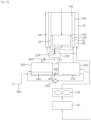
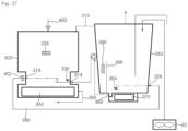
- a humidifier includes a water tank storing water, a heating device being supplied with water from the water tank and heating the water, a humidifying device connected with the heating water tank and producing humidified air using water supplied from the heating water tank, a first connection tube connecting the heating device and the humidifying device, a second connection tube connecting the heating device and the humidifying device at a position different from the first connection tube, and a pump disposed at a side of the second connection tube and supplying water stored in the humidifying device to the heating water tank. That is, it is possible to produce humidified air from sterilized water by supplying water heated in the heating device to the humidifying device through the first connection tube. Further, the pump is disposed at the second connection tube, whereby it is possible to supply water remaining in the humidifying device to the heating device. That is, it is possible to keep the water remaining in the humidifying device in a sterilized state through continuous heating.
- the humidifier further includes a valve opening/closing the first connection tube, and water in the heating water tank is supplied to the humidifying device when the valve is opened, so it is possible to selectively supply water heated in the heating device to the humidifying device.
- the humidifying device includes a humidifying water tank forming a space in which water is stored, and a vibration device disposed under the humidifying water tank and producing humidified air from water stored in the humidifying water tank through vibration, and the second connection tube is connected with the humidifying water tank at a side at which the vibration device is disposed, so it is possible to minimize water that remains in the humidifying water tank.
- the vibration device may be disposed on a bottom surface of the humidifying water tank, a return groove forming a space at a side of the vibration device may be formed at the humidifying water tank, and the second connection tube may be connected to the humidifying water tank at a side at which the return groove is formed.
- An inflow hole may be connected in a region connected with the first connection tube and a return discharge hole may be formed in a region connected with the second connection tube, in the humidifying water tank, and the return discharge hole may be formed at a position lower than the inflow hole.
- the second connection tube may include a pump inflow tube connecting the humidifying device and the pump and a pump discharge tube connecting the heating device and the pump, and the pump may be disposed higher than a region in which the second connection tube is connected to the humidifying water tank and the heating water tank.
- the humidifier includes a drain tube disposed on a side of the heating device and draining water in the heating device to the outside, whereby it is possible to remove remaining water in the heating device.
- the heating device includes a heating water tank forming a space in which water is stored, and a heater disposed under the heating water tank and heating water stored in the heating water tank, and the drain tube is disposed on a side of the heating water tank at which the heater is disposed, so it is possible to maximally remove remaining water in the hating water tank.
- the heater may be disposed to be spaced apart from an inner circumferential surface of the heating water tank, and a drain hole connected with the drain tube may be formed at the heating water tank on the side at which the heater is disposed.
- the humidifier includes a blowing fan generating airflow outside the heating device and the humidifying device, and an air guide cover supplying air flowing around the humidifying device into the humidifying device, so it is possible to generate airflow in the humidifying device.
- the humidifying device includes a lower extension wall disposed such that air flowing in the humidifying device through the air guide cover flows under the humidifying device, so it is possible to send air flowing in the humidifying device under the humidifying device.
- An exhaust hole is formed such that humidified air produced in the humidifying device is discharged out of the humidifying device and an air supply hole formed such that air flowing through the air guide cover flows into the humidifying device are formed in the humidifying device, and the lower extension wall is disposed between the exhaust hole and the supply hole, so air flowing into the humidifying device can be discharged after flowing in the humidifying device.
- the humidifying device includes an exhaust tube discharging humidified air produced in the humidifying device to the outside of the humidifying device, so humidified air produced in the humidifying device can be discharged outside.
- the humidifier further includes a connecting tube forming a connecting channel such that humidified air produced in the heating device flows to the humidifying device, so humidified air produced in the heating device can be discharged outside through the humidifying device.
- the connecting tube is connected to a top surface of the heating device and a first connecting hole through which humidified air produced in the heating device flows into the connecting tube is formed on the top surface of the heating device.
- An inner diameter of the first connection tube is larger than an inner diameter of the second connection tube, so it is possible to minimize the space in which water is disposed in the second connection tube.
- a humidifier of the present invention includes a heating device heating water, a humidifying device connected with the heating device and producing humidified air using water supplied from the heating device, a first connection tube connecting the heating device and the humidifying device such that heated water in the heating device is supplied to the humidifying device, a valve opening/closing the first connection tube, an exhaust tube discharging humidified air produced in the humidifying device to the outside of the humidifying device, and a blowing fan supplying air into the humidifying device.
- the humidifier has a structure in which air is supplied to the humidifying device and then discharged, so it is possible to dry water in the humidifying device.
- the humidifier further includes a drain tube disposed on a side of the heating device and draining water stored in the heating device to the outside of the heating device, so it is possible to drain water remaining in the heating water tank to the outside.
- a humidifier of the present invention includes a heating water tank being supplied with water from the water tank and heating the water, a humidifying water tank connected with the heating water tank and producing humidified air using water supplied from the heating water tank, a first connection tube connecting the heating water tank and the humidifying water tank, an exhaust tube discharging humidified air produced in the humidifying water tank to the outside of the humidifying water tank, a valve opening/closing the first connection tube, and a pump disposed at a side of the first connection tube and supplying water stored in the humidifying water tank to the heating water tank, so it is possible to supply water in the heating water tank to the humidifying water tank or supply water in the humidifying water tank to the heating water tank through one connection tube.
- the valve may be mounted on a side of the heating device and the pump may be mounted on a side of the humidifying device.
- humidified air produced in the humidifying device is discharged as sterilized humidified air using water sterilized through the heating device, there is an advantage that it is possible to provide pleasantness to a user. Since even water remaining in the humidifying device is supplied back to the heating device using the pump, there is an advantage that it is possible to prevent contaminated water produced when use is stopped from being used to produce humidified air.
- Humidified air in the heating device can be discharged through the humidifying device by the connecting tube connecting the heating device and the humidifying device. Further, since air blown by the blowing fan can flow to the heating device through the connection tube, it is also possible to dry the inside of the heating device. This may help keep the inside of the heating device clean.
- a humidifier of the present invention can vaporize water using ultrasonic vibration.
- a humidifier of the present invention can discharge humidified air by heating water.
- a humidifier of the present invention can discharge humidified air produced by ultrasonic vibration and humidified air produced by heating.
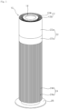
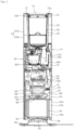
- a humidifier includes a case 10 forming an external shape and having an inlet 24a and an outlet 12a, a filter device disposed in the case 10 and filtering air suctioned into the inlet 24a, a blower 60 disposed in the case 10 and blowing air in the case 10 from the inlet 24a to the outlet 12a, a water tank 100 disposed in the case 10 and storing water, and a humidifying module being supplied with water from the water tank 100 and producing humidified air.
- the humidifying module may include a heating device 300 that heats water and a humidifying device 350 that produces humidified air from water.
- the humidifying module may include a humidifying module housing 410 circumferentially covering the heating device 300 and the humidifying device 350.
- a channel housing 430 may be circumferentially disposed outside the humidifying module housing 410.
- a blowing channel 70 may be formed between the humidifying module housing 410 and the channel housing 430.
- the entire case 10 may have a cylindrical shape.
- the case 10 may include an intake grill 24 forming the inlet 24a through which air flows inside and a discharge grill 12 forming the outlet 12a through which air is discharged.
- the inlet 24a may be formed on the circumferential surface of the case 10 having a cylindrical shape.
- the outlet 12a may be formed on the top surface of the case 10 having a cylindrical shape.
- the humidifier of the present invention can suction air through the circumferential surface and discharge air through the top surface.
- the intake grill 24 can cover the outer sides of a filter 50 and a blowing housing 68 to be described below.
- a plurality of inlets 24a formed in the up-down direction and circumferentially spaced apart from each other may be formed on the intake grill 24.
- the inlets 24a may be formed around the filter 50.
- the inlets 24a may be formed on the lower portion of the intake grill 24.
- the inlets 24a may be formed on the lower portion of the intake grill 24 and the upper portion of the intake grill 24 may be formed to be closed to protect the configuration inside the humidifier.
- a plurality of grills 24b extending in the up-down direction is disposed at the intake grill 24.
- the plurality of grills 24b may be disposed to be spaced apart from each other in the circumferential direction of the intake grill 24.
- a plurality of inlets 24a may be formed between the plurality of grills 24b.
- the intake grill 24 may be divided into a lower intake grill section 25a at which the inlets 24a are formed and an upper intake grill section 25b disposed over the lower intake grill section 25a.
- a display 30 to be described below may be disposed at the upper intake grill section 25b.
- the upper intake grill section 25b can cover the outer sides of the blowing housing 68 and the humidifying module to be described hereafter.
- the humidifier may include a discharge grill 12 forming the outlet 12a and a water tank cover 14 disposed over the water tank 100.
- the discharge grill 12 may have a structure that is separated upward from an outer shell 22 to be described below.
- the water tank cover 14 may have a structure that is separated from the discharge grill 12 or the water tank 100.
- the discharge grill 12 may include a plurality of ribs 12b radially extending from the outer circumferential portion of the water tank cover 14.
- the plurality of ribs 12b disposed at the discharge grill 12 may be disposed to be circumferentially spaced apart from each other on the outer circumference surface of the water tank cover 14.
- the water tank cover 14 may include a center cover 16 and an edge cover 18 disposed around the center cover 16.
- the center cover 16 may have a structure that becomes convex upward as it goes to the center.
- a water supply hole 20 through which water flows into the water tank 100 may be formed between the edge cover 18 and the center cover 16.
- the discharge grill 12 may be disposed over a first discharge channel 32 and over a second discharge channel 34 to be described below.
- the plurality of outlets 12a may be formed between the plurality of ribs 12b disposed at the discharge grill 12.
- the discharge grill 12 may have a predetermined height in the up-down direction. Accordingly, mixing channels 13 may be formed between the plurality of ribs 12b disposed at the discharge grill 12. Air flowing through the first discharge channel 32 and air flowing through the second discharge channel 34 can be mixed in the mixing channels 13.
- Each of the plurality of ribs 12b is formed such that the height of the outer circumferential end is larger than the height of the inner circumferential end. Accordingly, the air flowing through the first discharge channel 32 and the second discharge channel 34 can be guided radially inward.
- the case 10 may include an outer shell 22 that guides air flowing therein to the outlets 12a.
- the outer shell 22 may form an inner shell 180 to be described below and the second discharge channel 34.
- the outer shell 22 includes an upper outer shell 22a disposed under the discharge grill 12 and a lower outer shell 22b disposed under the upper outer shell 22a.
- the lower outer shell 22b may be made of a transparent material.
- the case 10 may include a bottom wall 26 covering the bottom of the intake grill 24.
- the humidifier may include a base 28 disposed under the case 10 and spacing the bottom wall 26 a predetermined distance apart from the ground.
- the upper end portion of the base 28 may connected with the bottom wall 26.
- the bottom wall 26 is disposed to cover the bottom surface of the humidifier spaced apart upward from the ground by the base 28.
- the display 30 is disposed on a side of the case 10.
- the display 30 enables a user to control the power or operation of the humidifier.
- a display showing the operation state, etc. of the humidifier to a user may be disposed at the display 30.
- the filter device can filter air suctioned inside through the inlets 24a using the filter 50.
- the filter device can blow filtered air upward.
- the filter device includes a filter 50 filtering air that is suctioned into the inlets 24a, and a filter mount fixing the filter 50 in the case 10.
- the filter 50 may have a cylindrical shape. Accordingly, the filter 50 can filter air that is suctioned in the front, rear, left, and right directions perpendicular to the up-down direction. Air suctioned into the inlet 24a can flow to an internal space of the filter 50. Air that has passed through the filter 50 can flow to the blower 60 disposed over the filter 50.
- the filter mount includes a lower plate 52 disposed under the filter 50, an upper plate 54 disposed on the filter 50, and supporters (not shown) connecting the lower plate 52 and the upper plate 54.
- the lower plate 52 is disposed under the filter 50.
- the lower plate 50 can sense whether the filter 50 is disposed while moving up and down.
- a fan sterilizer 53 that emits ultraviolet light upward may be disposed at the center of the lower plate 52.
- the fan sterilizer 53 can sterilize a blowing fan 62 to be described below or the inside of the filter 50.
- An orifice 56 is formed on the upper plate 54.
- the orifice 56 may be formed at the center of the upper plate 54.
- the orifice 56 can make air flowing in the filter 50 flow to the blowing fan 62.
- the inner circumferential end of the upper plate 54 has an upward bending shape, so it is possible to guide air flowing upward through the internal space of the filter 50 to the blowing fan 62.
- the supporters 58 can connect the lower plate 52 and the upper plate 54.
- the supporters 58 may be disposed to be circumferentially spaced apart from each other.
- the blower 60 includes a blowing fan 62 generating airflow in the case 10 and a fan motor 64 rotating the blowing fan 62.
- the blowing fan 62 may form a fan suction port at a side facing the orifice 56 and a fan discharge port opposite to the fan intake port.
- a mixed flow fan of which the fan discharge port faces the center of a circle at the opposite side to the fan intake port may be used as the blowing fan 62.
- the blowing fan 52 may include a hub connected with the fan motor 64, a shroud disposed to be spaced a predetermined distance apart from the hub and forming the fan intake port, and a blade radially extending to connect the hub and the shroud.
- the blowing fan 62 can operate to send air upward from the lower portion.
- the blowing fan 62 can suction air toward the orifice 56 and discharge air toward the blowing housing 68 in which a diffuser 72 is disposed.
- the fan motor 54 may be disposed over the blowing fan 52.
- the blower includes a motor cover 66 covering the outer side of the fan motor 64 and the blowing housing 68 disposed to be spaced apart radially outward from the motor cover 66 and guiding upward the air blown by the blowing fan 62.
- a blowing channel 70 through which the air blown by the blowing fan 62 flows upward may be formed between the motor cover 66 and the blowing housing 68.
- the blowing channel 70 may extend to the region in which a humidifying module housing 410 and a channel housing 430 are formed.
- the intake grill 24 may be disposed outside the blowing housing 68.
- the blower 60 includes the diffuser 72 disposed between the motor cover 66 and the blowing housing 68 and reducing the rotational component of the air blown upward by the blowing fan 62.
- a plurality of diffusers 72 may be disposed to be circumferentially spaced.
- a control box 74 forming a space in which a circuit board 76 is disposed therein may be disposed over the motor cover 66.
- the control box 74 may be disposed to be spaced apart inward from the blowing housing 68. Accordingly, the blowing channel 70 can be formed also in the space between the control box 74 and the blowing housing 68.
- a plurality of circuit board 76 may be disposed in the control box 74.
- a water tank, and an inner shell and an outer shell that are disposed outside the water tank are described with reference to Fig. 4 .
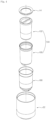
- the humidifier of the present invention includes a water tank 100 storing water, an inner shell 180 forming a space therein in which the water tank 100 is spaced, an outer shell 22 forming a space therein in which the inner shell 180 is disposed, and a water tank cover 14 disposed over the water tank 100.
- the water tank 100 includes an inner water tank 102 and an outer water tank 160 circumferentially disposed outside the inner water tank 102.
- the inner shell 180 is disposed inside the outer shell 22.
- the outer shell 22 and the inner shell 180 are disposed to be spaced apart from each other.
- a second discharge channel 34 through which air that has passed through the filter 50 may be formed between the outer shell 22 and the inner shell 180.
- the outer water tank 160 is disposed inside the inner shell 180.
- the inner shell 180 and the outer water tank 160 are disposed to be spaced apart from each other.
- the first discharge channel 32 (see Fig. 3 ) through which humidified air produced at the humidifying device 450 flows is formed between the inner shell 180 and the outer water tank 160.
- the inner water tank 102 is disposed in the outer water tank 160.
- the inner water tank 102 may be disposed in the outer water tank 160.
- the outer circumferential surface of the inner water tank 102 may be disposed to be in contact with the inner circumferential surface of the outer water tank 160.
- the water tank cover 14 is disposed over the inner water tank 102 and the outer water tank 160.
- the water tank 14 can cover the tops of the inner water tank 102 and the outer water tank 160.
- the water tank 14, which is a structure mounted on the discharge grill 12, may be disposed to be spaced upward a predetermined distance apart from the inner water tank 102 and the outer water tank 160.
- the inner water tank 102 includes an inner water tank body 104 forming a space in which water is stored, a handle 108 disposed over the inner water tank body 104, and a connector 120 disposed under the inner water tank body 104 and connecting the inner water tank body 104 to a supply tube 230 to be described below.
- the inner water tank body 104 may be formed in a substantially cylindrical shape.
- the inner water tank body 104 may have an upward open shape.
- the handle 108 is disposed over the inner water tank body 104.
- the handle 108 includes a handle bar 110 disposed across the top of the inner water tank body 104.
- the connector 120 includes a connector body 121 disposed through a bottom hole 106 of the inner water tank body 104 and a connector holder 132 fixing the connector body 121 by being coupled to the connector body 121.
- the connector body 121 is disposed in the inner water tank body 104 and the connector holder 132 is disposed under the inner water tank body 104.
- a water softener 14 that removes ions in water flowing in the inner water tank 102 is disposed in the inner water tank 102.
- the water softener 140 may be disposed to be fixed in the inner water tank 102.
- the inner water tank 102 includes an inner water tank body 104 forming a space in which water is stored, a handle 108 disposed over the inner water tank body 104, and a connector 120 disposed under the inner water tank body 104 and connecting the inner water tank body 104 to a supply tube 230 (see Fig. 16 ) to be described below.
- the inner water tank body 104 may be formed in a substantially cylindrical shape.
- the inner water tank body 104 may have an upward open shape.
- a bottom hole 106 through which stored water is discharged may be formed on the bottom surface of the inner water tank body 104.
- the inner water tank body 104 may have a shape in which the inner diameter of the water tank decreases downward from the upper portion.
- the bottom hole 106 may be formed at the center of the bottom surface of the inner water tank body 104.
- the connector 120 may be disposed to be fixed in the bottom hole 106. Water stored in the inner water tank 102 can flow to the supply tube 230 through the connector 120 mounted in the bottom hole 106.
- the handle 108 includes a handle fixing portion 112 disposed to be fixed to the upper end portion of the inner water tank body 104 and a handle bar 110 disposed across the top of the inner water tank body 104.
- the handle fixing portion 112 may have a structure held on the upper end of the inner water tank body 104.
- the handle fixing portion 112, in the region disposed in the inner water tank body 104, may include an inclined wall 113 inclined toward the inside and the underside of the inner water tank body 104. Accordingly, water that drops through the water tank cover 14 can flow on the inclined surface of the handle fixing portion 112 into the inner water tank 102
- the connector 120 may include a connector body 121 disposed through the bottom hole 106 of the inner water tank body 104, a connector holder 132 fixing the connector body 121 by being coupled to the connector body 121, and a connector valve 130 disposed in the connector body 121 and opening/closing the internal channel of the connector body 121.
- the connector body 121 includes a connector plate 122 disposed in the inner water tank body 104 and a connector pipe 128 disposed through the bottom hole 106 of the inner water tank body 104 and forming an internal channel 128a therein.
- the connector plate 122 is disposed over the bottom surface of the inner water tank body 104.
- the connector plate 122 may have a structure that fixes the water softener 140 to be described below in contact with the lower portion of the water softener 140.
- a plurality of fixing ribs 126a and 126b protruding upward and radially spaced apart from each other may be disposed on the connector plate 122.
- a bottom protrusion 148 of the water softener 140 may be disposed between the plurality of fixing ribs 126a and 126b.
- An edge wall 124 disposed radially further outside than the fixing ribs 126a and 126b and protruding upward may be disposed on the connector plate 122.
- a hook 149 of the water softener 140 may be inserted in a hook hole 124a formed at the edge wall 124.
- the connector pipe 128 may have a structure extending downward from the center of the connector plate 122.
- the connector pipe 128 is disposed through the bottom hole 106 of the inner water tank body 104.
- the internal channel 128a through which water in the inner water tank 102 flows may be formed in the connector pipe 128.
- the connector valve 130 opening/closing the internal channel 128a is disposed in the connector pipe 128.
- the connector valve 130 may be disposed to move in the up-down direction in the connector pipe 128.
- the connector valve 130 can open the internal channel 128a by moving upward.
- the connector holder 132 is circumferentially disposed to be fixed outside the inner water tank 128.
- the connector holder 132 may be disposed under the bottom surface of the inner water tank body 104. Accordingly, the connector holder 132 is connected with the connector pipe 128, thereby being able to fix the connector body 121.
- the inner water tank 102 may include a packing 114 mounted on the inner water tank body 104 forming the circumferential portion of the bottom hole 106.
- the packing 114 may be made of a rubber material.
- the packing 114 may be disposed to be in contact with the connector plate 122 at the upper side and in contact with the connector holder 132 at the lower side.
- the packing 114 can prevent contact of the inner water tank body 104 and the connector body 121.
- the packing 114 can prevent contact of the inner water tank body 104 and the connector holder 132.
- the packing 114 can seal the portion between the connector plate 122 and the bottom wall 105 of the inner water tank body 104. Further, the packing 114 can seal the portion between the connector holder 132 and the bottom wall 105 of the inner water tank body 104. That is, the packing 114 can doubly prevent water existing in the inner water tank 102 from leaking through the outside of the connector 120.
- An inner sealer 136 may be circumferentially disposed outside the connector plate 128.
- the inner sealer 136 can seal the portion between the connector 120 and the supply tube 130.
- An outer sealer 134 may be circumferentially disposed outside the connector holder132.
- the outer sealer 134 may be disposed to be in contact with a side of the outer water tank 160 (see Fig. 14 ) to be described below and/or the inner shell 180 (see Fig. 14 ).
- the water softener 140 may be disposed to be fixed in the inner water tank 102.
- An ion exchange resin (not shown) that removes ions of water flowing into the inner water tank 102 may be disposed in the water softener 140.
- the water softener 140 may include a gasket 152, which seals the inner circumferential surface of the inner water tank 102 and the outer circumferential surface of the water softener 140, at a side of the circumferential surface thereof.
- the gasket 153 disposed at the upper end portion of the water softener 140 may be disposed to be in contact with the inner circumferential surface of the inner water tank 102. Accordingly, water does not flow through the space between the inner water tank 102 and the water softener 140 while not passing through the inside of the water softener 140. Water flowing inside from above the inner water tank 102 and flowing to the bottom hole 106 of the inner water tank 102 can necessarily pass through the water softener 140.
- the water softener 140 is described with reference to Figs. 7 to 9b .
- the water softener 140 has a plurality of holes 146a and 150b through which water flows that is formed on the top surface and the bottom surface, respectively.
- the water softener 140 makes water, which flows inside through the hole 150b formed on the top surface, come in contact with and react with the ion exchange resin and discharges the water flowing in the water softener 140 through the hole 146a formed on the bottom surface.
- the gasket 152 protruding radially outward to come in contact with the inner circumferential surface of the inner water tank 102 is disposed on the circumferential surface of the water softener 140. Accordingly, water flowing downward from the inside of the inner water tank 102 flows through the water softener 140.
- the water softener 140 includes a water softener housing 142 forming a space therein in which the ion exchange resin (not shown) is disposed and a housing cover 150 disposed over the water softener housing 142.
- the water softener 140 includes the gasket 152 disposed to be fixed to the water softener housing 142 or the housing cover 150 and disposed to be in contact with the inner circumferential surface of the inner water tank 102.
- the water softener housing 142 may have a bowl shape being open on the top and forming a space therein.
- the water softener housing 142 includes a housing circumference wall 114 formed in a cylindrical shape, a housing bottom wall 146 forming the bottom surface of the housing circumference wall 144, and an inner protrusion 144a protruding inward from the upper end portion of the housing circumference wall 144.
- the housing circumference wall 144 may be formed in a shape of which the diameter decreases downward.
- the housing circumference wall 144 is disposed in the inner water tank 102.
- the housing circumference wall 144 may be disposed to be spaced a predetermined distance apart from the inner water tank 102.
- the inner protrusion 144a fixing the housing cover 150 disposed over it may be disposed at the upper end portion of the housing circumference wall 144.
- the inner protrusion 144a may have a structure protruding to the inner circumferential surface of the housing circumference wall 144.
- the inner protrusion 144a may have a circumferentially extending structure.
- a plurality of inner protrusions 144a may be provided and spaced apart from each other along the inner circumferential surface of the housing circumference wall 144. Referring to Fig. 8 , the inner protrusion 144a is disposed over an outer protrusion 151 formed at the housing cover 150, thereby being able to fixing the housing cover 150.
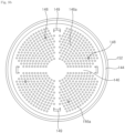
- a plurality of housing holes 146a is formed on the housing bottom wall 146. Water that has come in contact with the ion exchange resin can flow downward through the plurality of housing holes 146a.
- the plurality of housing holes 146a may be disposed inside the bottom protrusion 148 disposed on the bottom surface of the water softener 140. Further, referring to Fig. 9b , the plurality of housing holes 146a may be uniformly formed in the entire region of the housing bottom wall 146.
- the hook 149 connecting the water softener 140 to the connector 120 may be disposed at the housing bottom wall 146.
- the hook 149 may be mounted in the hook hole 124a formed on the edge wall 124 of the connector body 121.
- a plurality of hooks 149 may be disposed to be circumferentially spaced.
- the hook 149 can prevent the water softener 140 disposed over the connector 120 from moving upward in the inner water tank 102. Referring to Figs. 9a to 9b , a plurality of hooks 149 circumferentially spaced apart from each other may be provided.
- the bottom protrusion 148 may be disposed on the housing bottom wall 146.
- the bottom protrusion 148 protrudes downward from the housing bottom wall 146.
- the bottom protrusion 148 can space the water softener 140 disposed over the connector 120 a predetermined distance apart from the connector 120. Accordingly, water flowing under the water softener 140 through the housing hole 146a can flow between the connector 120 and the water softener 140 and to the internal channel 128a of the connector pipe 128.
- the bottom protrusion 148 may be disposed between a first fixing rib 126a and a second fixing rib 126b that are disposed on the connector body 121.
- the bottom protrusion 148 may be formed in a ring shape.
- the bottom protrusion 148 may be formed in a pillar shape protruding downward at a point on the housing bottom wall 146.
- the bottom protrusion 148 may have a structure that has a bottom surface of the shape formed by the housing hole 146 and protrudes downward.
- a plurality of pillar-shaped bottom protrusions circumferentially spaced apart from each other may be disposed. As in Fig. 9b , when pillar-shaped bottom protrusions are disposed, the number of the housing holes 146a formed on the housing bottom wall 146 may be increased.
- the housing cover 150 is disposed over the water softener housing 142.
- the housing cover 150 is disposed to cover the top of the water softener housing 142.
- the housing cover 150 can cover the open top of the water softener housing 142.
- a plurality of cover holes 150b is formed at the housing cover 150.
- the water stored in the inner water tank 102 can flow into the water softener housing 142 through the plurality of cover holes 150b.
- a housing handle 150a protruding upward is disposed on the top of the housing cover 150.
- the outer protrusion 151 protruding radially outward is disposed at a side on the circumferential surface of the housing cover 150.
- the inner protrusion 144a of the water softener housing 142 is disposed under the outer protrusion 151 of the housing cover 151, whereby the housing cover 150 can be fixed.
- the gasket 152 may be disposed at the upper end portion of the housing cover 150.
- the gasket 152 may be disposed to protrude radially outward from the upper end portion of the housing cover 150.
- the gasket 152 is disposed to protrude radially outward further than the housing cover 150 or the water softener housing 142. Accordingly, when the water softener 140 is disposed in the inner water tank 102, the outer circumferential surface of the gasket 152 is disposed to be in contact with the inner circumferential surface of the inner water tank 102.
- the diameter of the outer circumferential surface of the gasket 152 may be larger than the diameter of the inner circumferential surface of the inner water tank 102 in the region in which the gasket 152 is positioned. Accordingly, water flowing downward from the inner water tank 102 can flow downward through the inside of the water softener 140.
- the connector is described with reference to Fig. 10 .
- the connector 120 connects the inner water tank 102 and the supply tube 230.
- the connector 120 can fix the water softener 140 disposed in the inner water tank 102.
- the connector 120 is connected to the water tank 100 and can discharge the water stored in the water tank 10 to the humidifying module.
- the connector 120 can discharge the water stored in the water tank 100 to the humidifying module through the supply tube 230.
- the connector 120 of the present invention may include a connector body 121 and a connector holder 132.
- the connector body 121 is disposed over the connector holder 132.
- the connector body 121 may be disposed over the inner water tank body 104 (see Fig. 6 ).
- the connector holder 132 may be disposed under the inner water tank body 104 (see Fig. 6 ).
- the connector body 121 may include a connector plate 122 and a connector pipe 128 extending downward from the connector plate 122.
- the connector pipe 128 has a structure protruding downward from the connector plate 122.
- a connector valve 130 is disposed in the internal channel 128a formed in the connector pipe 128.
- a pipe protrusion 129 is disposed on the outer circumferential portion of the connector pipe 128.
- the pipe protrusion 129 is disposed over the holder protrusion 133 of the connector holder 132, whereby the connector body 121 and the connector holder 132 can be fixed.
- the inner sealer 136 is circumferentially disposed outside the connector pipe 128. When the connector 120 is disposed over the supply tube 230 to be described below, an inner sealer 136 can seal the portion between the connector 120 and the supply tube 230.
- the inner sealer 136 may be disposed under the pipe protrusion 129.
- the connector holder 132 may be disposed to be fixed to the connector pipe 128.
- An outer sealer 134 is disposed on the outer circumferential surface of the connector holder 132.
- the outer sealer 134 is disposed to protrude radially outward further than the circumferential surface of the connector holder 132.
- the outer sealer 134 may be disposed to be in contact with the inner circumferential surface of a bottom protrusion 166 (see Fig. 14 ) of the outer water tank 160 disposed outside the connector holder 132.
- the outer sealer 134 may be disposed over a top protrusion 186 (see Fig. 14 ) of the inner shell 180 disposed outside the connector holder 132.
- Fixing ribs 126a and 126b protruding upward may be disposed on the connector plate 122.
- the fixing ribs 126a and 126b may include a first fixing rib 126a and a second fixing rib 126b disposed to be radially spaced apart from the first fixing rib 126a.
- the bottom protrusion 148 (see Fig. 8 ) of the water softener 140 may be disposed in the space between the first fixing rib 126a and the second fixing rib 126b.
- the first fixing rib 126a and the second fixing rib 126b can prevent the water softener 140 disposed in the inner water tank 102 from moving in a direction perpendicular to the up-down direction.
- An edge wall 124 disposed radially further outside than the fixing ribs 126a and 126b and protruding upward may be disposed on the connector plate 122.
- a hook hole 124a in which the hook 149 of the water softener 140 is inserted may be formed at the edge wall 124.
- the connector holder 120 may have a structure that is hollow and open in the up-down direction.
- the holder protrusion 133 is disposed to protrude on the inner circumferential surface of the connector holder 132.
- the connector pipe 128 of the connector body 121 may be inserted in the space formed inside the inner circumferential surface of the connector holder 132.
- the outer sealer 134 radially protruding may be disposed at the upper end portion of the connector holder132.
- a water tank, an inner shell, and a middle tray are described with reference to Fig. 13 .
- the humidifier includes a water tank 100 forming a space in which water is stored, an inner shell 180 forming a space in which the water tank 100 is disposed, and a middle tray 200 disposed under the inner shell 180.
- the water tank 100 may be in the state in which the inner water tank 102 is disposed in an outer water tank 160. Accordingly, the connector holder 132 may be disposed in a through-hole 164 of the outer water tank 160.
- the outer water tank 160 may be disposed, with the inner shell 180 disposed therein, over the middle tray 200.
- the middle tray 200 may be a structure supporting the inner shell 180, the outer water tank 160, and the inner water tank 102. Accordingly, the load of the inner water tank 102, the outer water tank 160, and the inner shell 180 can be transmitted to the middle tray 200.
- the outer water tank 160 is circumferentially disposed outside the inner water tank 102.
- the through-hole 164 is formed on the bottom surface of the outer water tank 160 and some components of a connector 120 may be disposed under the outer water tank 160 through the through-hole 164.
- a pair of first water tank protrusions 170a and 170b protruding downward from the bottom surface of the outer water tank 160 and a second water tank protrusion 168 protruding downward from the bottom surface of the outer water tank 160 may be disposed on the bottom surface of the outer water tank 160.
- the pair of first water tank protrusions 170a and 170b may be disposed opposite to each other with the through-hole 164 therebetween.
- the pair of first water tank protrusions 170a and 170b can transmit the load of the inner water tank 102 and the outer water tank 160 to weight sensors 212a and 212b of the middle tray 200 to be described below.
- the pair of first water tank protrusions 170a and 170b can transmit the load of the inner water tank 102 and the outer water tank 160 to the weight sensors 212a and 212b (see FIG. 14 ) directly or indirectly through the inner shell 180.
- the second water tank protrusion 168 may be disposed between the pair of first water tank protrusions 170a and 170b.
- the inner shell 180 can form a space in which the water tank 100 is disposed.
- a shell through-hole 184 is formed on the bottom surface of the inner shell 180.
- the shell through-hole 184 is disposed under the through-hole 164 of the outer water tank 160.
- the connector 120 may be disposed in the shell through-hole 184.
- a pair of first shell protrusions 188a and 188b in which the pair of first water tank protrusions 170a and 170b of the outer water tank 160 is mounted may be disposed at the inner shell 180.
- the pair of first shell protrusions 188a and 188b may have a structure protruding downward from the bottom surface of the inner shell 180.
- a second shell protrusion 190 in which the second water tank protrusion 168 of the outer water tank 160 is mounted may be disposed at the inner shell 180.
- a space in which the second water tank protrusion 168 is inserted may be formed in the second shell protrusion 190.
- An exhaust connection tube 192 formed such that humidified air discharged from the humidifying module flows therethrough is disposed on the bottom surface of the inner shell 180.
- An exhaust connection tube hole 194 is formed in the exhaust connection tube 192.
- the middle tray 200 is disposed under the inner shell 180.
- a first hole 204 through which a supply tube 230 is disposed is formed on the middle tray 200.
- the first hole 204 may be formed at the center of a tray plate 202.
- a second hole 208 through which humidified air discharged from the humidifying device 350 flows is formed on the middle tray 200.
- the second hole 208 may be disposed at a position radially spaced apart from the first hole 204.
- the water tank, the inner shell, and the middle tray are described with reference to FIG. 14 .
- the inner water tank 102 may be disposed in the outer water tank 160.
- the outer circumferential surface of the inner water tank 102 may be disposed to be in contact with the inner circumferential surface of the outer water tank 160.
- the outer water tank 160 is circumferentially disposed outside the inner water tank 102.
- the outer water tank 160 may be disposed to be in contact with the outer circumferential portion of the inner water tank 102. Accordingly, it is possible to minimize condensate water that is produced on the outer circumferential portion of the inner water tank 102.
- the upper end portion 162 of the outer water tank 160 may be formed to be spaced apart from the inner water tank 102. That is, the upper end portion 162 of the outer water tank 160 may be formed such that the radial expansion ratio increases as it goes upward.
- the water softener 140 is disposed in the inner water tank 102.
- the water softener 140 is connected with the connector 120 disposed in the inner water tank 102, whereby the water softener 140 can be fixed.
- a gasket 152 is disposed at the upper end portion of the water softener 140 to be in close contact with the inner circumferential surface of the inner water tank 102. Accordingly, water flowing in the inner water tank 102 can flow down through the water softener 140.
- the inner shell 180 is disposed to be spaced apart from the outer water tank 160.
- the inner shell 180 is disposed to be spaced apart from the water tank 100.
- the first discharge channel 32 through which humidified air flows is formed between the inner shell 180 and the outer water tank 160.
- the first water tank protrusions 170a and 170 of the outer water tank 160 are inserted in the first shell protrusions 188a and 188b of the inner shell 180, whereby the outer water tank 160 can be fixed.
- the inner shell 180 may have a structure to which the load of the outer water tank 160, the inner water tank 102, and the water softener 140 is transmitted.
- the first discharge channel 32 is formed between the inner shell 180 and the outer water tank 160. Humidified air produced in the humidifying device 350 or the heating device 300 to be described below can flow through the first discharge channel 32.
- the inner shell 180 may be made of a transparent material.
- the inner shell 180 is disposed over the middle tray 200.
- the weight sensors 212a and 212b are disposed on the middle tray 200 at the portions that are in contact with the inner shell 180.
- the weight sensors 212a and 212b can sense the level of water stored in the inner water tank 102 by sensing the load of the inner shell 180, the outer water tank 160, the inner water tank 102, and the water softener 140.
- the first shell protrusions 188a and 188b of the inner shell 180 may be disposed on the weight sensors 212a and 212b of the middle tray 200.
- the first hole 204 may be formed on the middle tray 200.
- the first hole 204 is disposed at the center of the middle tray 200.
- the supply tube 230 may be disposed through the first hole 204 of the middle tray 200.
- the middle tray 200 includes the tray plate 202 disposed under the inner shell 180 and the lamp housing 218 disposed around the tray plate 202.
- the lamp housing 218 is disposed around the tray plate 202.
- the lamp housing 218 may have a ring-shaped structure.
- the lamp housing 218 may be disposed to protrude upward from the tray plate 202.
- a lamp 216 that emits light upward is disposed inside the lamp housing 218.
- a plurality of lamps 216 circumferentially spaced apart from each other may be disposed in a ring-shaped space formed by the lamp housing 218.
- the lamp 216 can emit light to the upper portion at which the inner shell is disposed.
- the lamp 216 can emit light to the first discharge channel 32 formed by the inner shell 180 and the outer water tank 160. Accordingly, humidified air flowing through the first discharge channel 32 can be visually seen from the outside.
- Humidified air produced in the humidifying device 350 or the heating device 300 can flow to the first discharge channel 32 through an exhaust tube 382. Humidified air can be discharged outside through the first discharge channel 32. Further, condensate water produced in the first discharge channel 32 can flow into the humidifying device 350 through the exhaust tube 382.
- the exhaust tube 382 disposed over the humidifying water tank 352 is disposed under the second hole 208 of the middle tray 200.
- the inner shell 180 and the outer shell 22 are disposed to be spaced apart from each other, thereby forming the second discharge channel 34. Filtered clean air blown by the blower 60 can flow through the second discharge channel 34.
- a second shell protrusion 190 in which the second water tank protrusion 168 of the outer water tank 160 is mounted may be disposed at the inner shell 180.
- a space in which the second water tank protrusion 168 is inserted may be formed in the second shell protrusion 190.
- An exhaust connection tube 192 that guides humidified air discharged from the humidifying device 350 to the first discharge channel 32 is disposed at the inner shell 180.
- the exhaust connection tube 192 may have a structure extending downward from the bottom surface of the inner shell 180.
- the exhaust connection tube 192 may have a shape corresponding to the exhaust tube 382.
- the lower end portion of the exhaust connection tube 192 may be connected with the upper end portion of the exhaust tube 382.
- the lower end portion of the exhaust connection tube 192 may be disposed inside further than the upper end portion of the exhaust tube 382.
- the supply tube is described with reference to Fig. 16 .
- the humidifier of the present invention includes the supply tube 230 for supplying water stored in the water tank 100 to the heating device 300.
- the supply tube 230 is disposed between the water tank 100 and the heating device 300.
- the supply tube 230 can temporarily store water that is discharged from the water tank 100 and supplied to the heating device 300.
- a supply chamber 232 in which water is temporarily stored may be formed in the supply tube 230.
- a sensor 234 that senses the inclination of water stored in the supply tube 230 may be disposed on a side of the supply tube 230.
- the supply tube 230 may be a structure formed by combining a plurality of configurations.
- the supply tube 230 may be formed by combining a first upper cover 322 and a supply tube cover 231 to be described below.
- the supply tube cover 231 may be a structure disposed over the first upper cover 322 and forming the supply chamber 232 therein by being combined with the first upper cover 322. Unlike the figures, the supply tube may be formed as a single structure.
- the supply tube 230 includes an upper supply tube 230a connected with the connector 120, a middle supply tube 230b extending downward from the upper supply tube 230a, and a lower supply tube 230c extending from the bottom of the middle supply tube 230b in a direction perpendicular to the up-down direction.
- the upper supply tube 230a may be disposed over the middle tray 200.
- the upper supply tube 230a may have a structure extending upward through the first hole 204 of the middle tray 200.
- the middle supply tube 230b may extend downward from the upper supply tube 230a and may have a cylindrical shape.
- the diameter of the middle supply tube 230b may be larger than the diameter of the upper supply tube 230a.
- the lower supply tube 230c may extend from a side of the middle supply tube 230b in a direction perpendicular to the up-down direction.
- the lower supply tube 230c can form the supply chamber 232 together with the first upper cover 322 disposed over the heating device 300 disposed thereunder.
- the lower supply tube 230c may be formed between the supply tube cover 231 and the first upper cover 322.
- the first upper cover 322 may have a chamber groove 324 recessed downward in the region in which the lower supply tube 230c is formed.
- a first valve 400 is disposed at an end of the lower supply tube 230c.
- the channel formed by the supply tube cover 231 and the first upper cover 322 may have a narrow channel shape and the first valve 400 is disposed at an end thereof.
- the channel formed at the end of the supply tube 230 can be opened/closed, depending on disposition of the first valve 400.
- the first valve 400 can supply water or stop supply of water from the supply tube 230 to the heating water tank 302.
- a first supply hole 325 may be formed in the first upper cover 322.
- the water existing in the supply chamber 232 can flow to the heating water tank 302 through the first supply hole 325.
- the first valve 400 can supply the water stored in the supply chamber 232 to the heating device 300 by opening/closing the first supply hole 325.
- a sensor 234 that senses the quality of the water existing in the supply chamber 232 may be disposed on the supply tube 230.
- the sensor 234 may disposed on a side of the middle supply tube 230b.
- the sensor 234 may be disposed at the upper portion of the middle supply tube 230b.
- the sensor 234 can measure the quality of water by measuring the electrical conductivity of the water. That is, it is possible to sense the concentration of ions by measuring electrical conductivity of water.
- the sensor 234 may disposed at the upper portion of the middle supply tube 230b, so the sensor 234 can quickly sense the quality of water that is supplied from the water tank 100. That is, when the water existing in the supply chamber 232 moves down and the water in the water tank 100 flows inside, it is possible to sense the quality of the water flowing inside from the water tank 100.
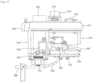
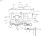
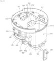
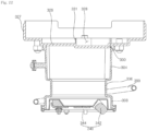
- a humidifying module is described with reference to Figs. 17 to 22 .
- the humidifier of the present invention may include a humidifying module that heats water and produces humidified air.
- the humidifying module may include a heating device 300 that heats water and a humidifying device 350 that produces humidified air using a vibration device 370.
- the humidifying module may include a first connection tube 390 and a second connection tube 392 that connect the heating device 300 and the humidifying device 350.
- the humidifier may include the first connection tube 390 and the second connection tube 392 that connect the heating device 300 and the humidifying device 350.
- the first connection tube 390 can supply water heated at the heating device 300 to the humidifying device 350.
- a second valve 402 is disposed in the first connection tube 390. The second valve 402 can supply water heated at the heating device 300 to the humidifying device 350 by opening/closing the internal channel of the first connection tube 390.
- a pump 404 is disposed at the second connection tube 392.
- the pump 404 When the pump 404 is operated, the water in the humidifying device 350 can flow to the heating device 300.
- the humidifier includes a drain tube 394 for draining water existing in the heating device 300 and a drain tube valve 396 disposed at an end of the drain tube 394 and opening/closing the drain tube 394.
- the drain tube 394 may be connected to a side of the heating device 300.
- the drain tube valve 396 may be disposed at an end of the drain tube 394.
- the drain tube 394 can discharge the water stored in the heating water tank 302 to the outside.
- the drain tube 394 may extend outside the humidifying module housing 410 (see Fig. 24 ).
- the humidifier includes a first temperature sensor 336 that senses the temperature of the water stored in the heating device 300 and a first water level sensor 338 that senses the level of the water stored in the heating device 300.
- a first temperature sensor 336 that senses the temperature of the water stored in the heating device 300
- a first water level sensor 338 that senses the level of the water stored in the heating device 300. Referring to Fig. 18 , the first temperature sensor 336 and the first water level sensor 338 are disposed on a side of the heating device 300.
- the humidifier includes a second temperature sensor 364 that senses the temperature of the water stored in the humidifying device 350 and a second water level sensor 366 that senses the level of the water stored in the humidifying device 350.
- the second temperature sensor 364 and the second water level sensor 366 are disposed on a side of the humidifying device 350.
- the humidifier includes a sensor 234 that senses the quality of the water existing in the supply tube 230.
- the sensor 234 is disposed on a side of the supply tube.
- the sensor 234 can sense the quality of the water flowing from the water tank 100.
- the sensor 234 can sense the replacement time of the water softener 140 disposed in the water tank 100 by sensing the quality of water.
- the humidifier may include a notifier (not shown) that provides notification to a user and a data storage (not shown) that accumulatively stores data showing the degree of purification of water that is sensed by the sensor 234.
- the first valve 400 can open an end of the supply tube 230.
- the notifier can be operated. The notifier can provide a user with notification about replacement of the ion exchange resin disposed in the water softener 140.
- the set level of the degree of purification of water may be set in advance in the humidifier.
- the set level of the degree of purification of water may be differently set in accordance with references.
- the notifier can provide a first alarm notifying of whether to replace the ion exchange resin to a user. Further, the notifier can provide a second alarm notifying of whether the water softener 140 has been mounted to a user.
- the notifier can provide first notification notifying of replacement of the ion exchange resin stored in the water softener 140.
- the notifier can provide second notification for checking whether the water softener 140 has been mounted.
- the case in which the inclination of a variation amount of the degree of purification of water that is accumulated in the data storage is out of a set range may be generated due to un-mounting of a water softener regardless of use of the water softener. Accordingly, it is possible to make a user check whether a water softener has been mounted through second notification.
- the heating device 300 may include a heating water tank 302 forming a space therein in which water is stored and a heater 340 disposed under the heating water tank 302 and heating the water in the heating water tank 302.
- the heating water tank 302 may have a cylindrical shape in which water is stored.
- the underside of the heating water tank 302 may be open and the heater 340 may be disposed under the heating water tank 302.
- the heating water tank 302 may include a lower water tank wall 308, a middle water tank wall 306, and an upper water tank wall 304.
- the lower water tank wall 308, the middle water tank wall 306, and the upper water tank wall 304 may be disposed in parallel upward from the lower side.
- the heater 340 may be disposed at the lower water tank wall 308.
- the heater 340 may be disposed to protrude to the inside of the lower water tank wall 308. However, the heater 340 may be disposed to be spaced radially inward from the inner circumferential surface of the lower water tank wall 308.
- the lower water tank wall 308 may be disposed to be spaced a predetermined distance from the heater 340 disposed therein.
- a drain hole 318 is formed on a side of the lower water tank wall 308.
- the heater 340 may include a heating body 342 that is supplied with electricity and generates heat and a heating plate 344 that is disposed to be in contact with the heating body 342.
- the heating body 342 may be formed in a ring shape with an open side.
- the heating body 342 may be disposed in the lower water tank wall 308.
- the heating plate 344 is disposed over the heating body 342 and transmits heat generated by the heating body 342 to the inside of the heating water tank 302.
- the heating plate 344 may be disposed to cover the heating body 342.
- a portion of the heating plate 344 may be disposed to protrude into the lower water tank wall 308 to cover the heating body 342.
- the heating plate 344 disposed in the lower water tank wall 308 may be disposed to be spaced apart from the inner circumferential surface of the lower water tank wall 308.
- the middle water tank wall 306 is disposed over the lower water tank wall 308.
- the diameter of the middle water tank wall 306 may be smaller than the diameter of the lower water tank wall 308 or the diameter of the upper water tank wall 304.
- the diameter of the middle water tank wall 306 is small, a space in which the configuration of the second valve 402 is disposed can be formed in the humidifying module housing 410. Since the diameter of the middle water tank wall 306 is small, a space in which the configuration of the first connection tube 390 is disposed can be formed in the humidifying module housing 410.
- the first temperature sensor 336 is disposed on a side of the middle water tank wall 306.
- a return inflow hole 314 through which water flows inside from the second connection tube 392 is formed on a side of the middle water tank wall 306.
- An outflow hole 316 through which water flows out to the first connection tube 390 may be formed on the middle water tank wall 306.
- the outflow hole 316 may be disposed at a higher position than the return inflow hole 314.
- the first temperature sensor 336 may be disposed at a higher position than the return inflow hole 314.
- the outflow hole 316 may be disposed at a position higher than or the same as the first temperature sensor 336.
- the first temperature sensor 336 can sense the temperature that is changed due to heating of the water supplied to the heating water tank 302. Further, the first temperature sensor 336 can sense the temperature of the water in the heating water tank 302 after a portion of the water in the heating water tank 302 is supplied to the humidifying water tank 352.
- the first temperature sensor 336 can sense temperature variation in the heating water tank 302.
- the first temperature sensor 336 can sense abnormal operation of the heater 340 in the heating water tank 302.
- the upper water tank wall 304 may extend upward from the middle water tank wall 306.
- the diameter of the upper water tank wall 304 may be larger than the diameter of the middle water tank wall 306.
- the extension length of the upper water tank wall 304 in the up-down direction may be larger than the extension length of the middle water tank wall 308 in the up-down direction.
- the size of the internal space occupied by the upper water tank wall 304 may be larger than the size of the internal space formed by the middle water tank wall 306 and the lower water tank wall 308.
- the first water level sensor 338 is disposed on a side of the upper water tank wall 304.
- the first water level sensor 338 is disposed higher than the first temperature sensor 336.
- the first water level sensor 338 can sense the level of the water in the heating water tank 302.
- the first water level sensor 338 can sense the normal level of water in the heating water tank.
- the normal level of water in the heating water tank 302 may mean the region between the upper end at which water supplied in the heating water tank 302 does not exceed a set water level and the lower end that is the minimum water level at which water has to exist to operate the heater 340.
- the heating device 300 may include upper covers 322 and 324 disposed over the heating water tank 302.
- the upper covers 322 and 324 are disposed over the upper water tank wall 304.
- the upper covers 322 and 324 may be disposed to cover at least a portion of the top of the heating water tank 302.
- the upper covers 322 and 324 may include a first upper cover 322 and a second upper cover 326 disposed under the first upper cover 322.
- the first upper cover 322 is disposed over the second upper cover 326.
- the first upper cover 322 can separate the heating water tank 302 and the supply tube 230.
- the first upper cover 322 can form a side of the supply chamber 232 forming the inside of the supply tube 230.
- the first upper cover 322 has a first supply hole 325 through which water stored in the supply chamber 232 flows.
- the first valve 400 is disposed over the first supply hole 325 and can open/close the first supply hole 325.
- the first upper cover 322 may be disposed to be spaced upward apart from the upper end of the upper water tank wall 304.
- the first upper cover 322 may have a structure connected with an exhaust tube 382 to be described below.
- the first upper cover 322 may be integrally formed with the exhaust tube 382.
- the first upper cover 322 may have an area smaller than the second upper cover 326.
- the first upper cover 322 may be disposed to be spaced upward apart from the second upper cover 326. That is, the first upper cover 322 may be disposed to be spaced upward further than the second upper cover 326.
- a portion of the first upper cover 322 may constitute a portion of the supply tube 230.
- the first upper cover 322 can form a chamber groove 324 recessed downward in the region in which the supply tube 230 is formed.
- the second upper cover 326 may be disposed to cover the first supply hole 325 formed at the first upper cover 322.
- a second supply hole 330 for sending water that flows through the first supply hole 325 to the heating water tank 302 may be formed at the second upper cover 326.
- the second supply hole 330 is disposed to be spaced apart from the first supply hole 325 in a direction perpendicular to the up-down direction.
- a supply channel 328 through which water flowing to the first supply hole 325 flows to the second supply hole 330 may be formed between the second upper cover 326 and the first upper cover 322.
- a supply channel rib 331 protruding upward to form the supply channel 328 may be disposed on the second upper cover 326.
- the supply channel rib 331 may be disposed to protrude upward from the second upper cover 326 and to be in contact with the bottom surface of the first upper cover 322.
- the extension direction of the supply channel 328 may be inclined with respect to the extension direction of the chamber groove 324. As one embodiment, the extension direction of the supply channel 328 may be perpendicular to the extension direction of the chamber groove 324.
- the second supply hole 330 may be formed in the region in which the circumference wall of the heating water tank 302 is positioned. Accordingly, the water flowing through the supply channel 328 can flow downward along the circumference wall of the heating water tank 302 when flowing to the heating water tank 302 through the second supply hole 330. Accordingly, the dropping noise of water that is supplied to the heating water tank 302 can be reduced.
- a first connecting hole 311a may be formed at the second upper cover 326.
- the first connecting hole 311a can connect the heating water tank 302 and the humidifying water tank 352. That is, humidified air produced in the heating water tank 302 can flow to the humidifying water tank 352 through the first connecting hole 311a.
- the first connecting hole 311a may have a structure that is open in the up-down direction. Accordingly, humidified air produced by the heater 340 in the heating water tank 302 can flow upward through the first connecting hole 311a.
- the second upper cover 326 may include an upper rib 333 extending upward around the first connecting hole 311a.
- the upper rib 333 may have a structure protruding upward around the second upper cover 326 at which the first connecting hole 311a is formed.
- the upper cover 312 may be disposed over the second upper cover 326.
- the upper cover 312 may have a structure connected with the upper rib 333.
- the upper cover 312 can form a connecting channel 311 therein together with the upper rib 333.
- the connecting channel 311 can connect the first connecting hole 311a formed at the heating water tank 302 and the second connecting hole 311b formed at the humidifying water tank 352.
- the connecting channel 311 may be disposed over the heating water tank 302. Accordingly, humidified air produced in the heating water tank 302 and flowing upward can flow to the connecting channel 311 through the first connecting hole 311a.
- the connecting channel 311 may be formed by the upper rib 333 of the second upper cover 326 and the upper cover 312.
- the connecting channel 311 extends level to the second connecting hole 311b.
- the humidifying device 350 includes the humidifying water tank 352 forming a space therein in which water is stored, and the vibration device 370 disposed under the humidifying water tank 352 and vibrating to atomize the water in the humidifying water tank 352.
- the humidifying water tank 352 may have a pillar shape forming a space therein.
- the vibration device 370 is disposed under the humidifying water tank 352.
- the humidifying water tank 352 may have a shape of which the cross-sectional area horizontally formed increases upward.
- the upper end of the humidifying water tank 352 may be higher than the upper end of the heating water tank 302.
- the vibration device 370 is disposed on the bottom surface of the humidifying water tank 352.
- An inflow hole 358 through which the water in the heating water tank 302 is supplied may be formed on a side of the humidifying water tank 352.
- a return discharge hole 360 through which the water in the humidifying water tank 352 flows to the heating water tank 302 may be formed on a side of the humidifying water tank 352.
- the inflow hole 358 may be formed at a position lower than an outflow hole 316 formed at the heating water tank 302.
- the return discharge hole 360 may be formed at a position lower than the inflow hole 358.
- the vibration device 370 may be disposed on the bottom surface of the humidifying water tank 352.
- the return groove 361 may be formed at a side of the vibration device 370. That is, the return groove 361 is disposed at a side of the vibration device 370 disposed on the bottom surface of the humidifying water tank 352. That is, the return groove 361 can form a space at the lower end portion inside the humidifying water tank 352.
- the return discharge hole 360 may be formed at a position lower than the return inflow hole 314 formed at the heating water tank 302.
- the second temperature sensor 364 is disposed at a side on the circumferential surface of the humidifying water tank 352.
- the second temperature sensor 364 may be disposed at a higher position than the return discharge hole 360.
- the second temperature sensor 364 may be disposed at a position lower than or the same as the inflow hole 358.
- the second temperature sensor 364 can sense the temperature of water supplied to the humidifying water tank 352. Accordingly, the second temperature sensor 364 can sense whether water at a temperature over a set temperature is supplied into the humidifying water tank 352
- the second water level sensor 366 is disposed at a side on the circumferential surface of the humidifying water tank 352.
- the second water level sensor 366 senses the level of the water existing in the humidifying water tank 352.
- the second water level sensor 366 can sense the minimum water level in the humidifying water tank 352 at which the vibration device 370 can operate. Further, the second water level sensor 366 can sense the amount of water stored in the humidifying water tank 352.
- the second water level sensor 366 can sense the optimal water level for operation of the vibration device 370.
- a water level sensor cover 368 may be disposed in the humidifying water tank 352.
- the water level sensor cover 368 may be disposed at a predetermined distance from the second water level sensor 366.
- the water level sensor cover 368 may be disposed between the second water level sensor 366 and the vibration device 370.
- the water level sensor cover 368 may have a structure protruding upward from the bottom surface of the humidifying water tank 352.
- the second water level sensor 366 can sense a more accurate water level by the water level sensor cover 368.
- the second connecting hole 311b is formed at the upper end portion of the circumference wall of the humidifying water tank 352.
- the second connecting hole 311b is formed at the upper end portion of the circumference wall of the humidifying water tank 352.
- the second connecting hole 311b is open in the direction in which the heating water tank 302 is disposed.
- the second connecting hole 311b is connected to the connecting channel 311.
- the second connecting hole 311b is horizontally open.
- Two vibration devices 370 may be disposed on the bottom surface of the humidifying water tank 352.
- the two vibration devices 370 may be disposed to be spaced apart from each other in a direction perpendicular to the up-down direction.
- the vibration device 370 includes vibration element 372 generating vibration and a vibration element cover 374 disposed over the vibration element 372.
- the vibration element cover 374 is disposed to be in contact with the water stored in the humidifying water tank 352.
- the vibration element cover 374 transmits vibration generated by the vibration element 372 to the water in the humidifying water tank 352.
- the vibration device 370 produces humidified air using the water stored in the humidifying water tank 352.
- the humidifying device 350 includes a humidifying water tank cover 380 disposed over the humidifying water tank 352.
- the humidifying water tank cover 380 can supply humidified air produced inside the humidifying water tank 352 to the first discharge channel 32.
- the humidifying water tank cover 380 includes an exhaust tube 382 for sending humidified air upward.
- the exhaust tube 382 may have a structure extending upward from the humidifying water tank cover 380.
- the exhaust tube 382 may have a substantially elliptical pillar shape.
- the exhaust tube 382 is disposed over a pair of vibration devices 370. Accordingly, humidified air produced by the vibration devices 370 can quickly flow to the exhaust tube 382. Further, when water in the humidifying water tank 352 is splashed upward by the vibration devices 370, the water can move into the exhaust tube 382.
- the upper end of the exhaust tube 382 may be disposed to be in contact with the middle tray 200. In this configuration, the upper end of the exhaust tube 382 may be disposed to be in direct contact with the middle tray 200 or in indirect contact with the middle tray 200 through a separate sealing member 388.
- An exhaust tube inlet 382a (or an exhaust hole) is formed on the lower end of the exhaust tube 382.
- An exhaust tube outlet 382b is formed on the upper end of the exhaust tube 382.
- the exhaust tube 382 can form an exhaust tube channel 383 between the exhaust tube inlet 382a and the exhaust tube outlet 382b.
- Humidified air produced in the humidifying device 350 can be discharged out of the humidifying device 350 through the exhaust tube inlet 382a (or an exhaust hole).
- An air supply hole 387a is formed at a side of the humidifying water tank cover 380. External air can flow into the humidifying water tank 352 through the air supply hole 387a.
- the air supply hole 387a may have an upward open shape.
- the humidifying water tank cover 380 includes an air guide cover 386 for supplying air flowing through the blowing channel 70 to the humidifying water tank 352.
- the air guide cover 386 makes a portion of air, which flows outside the humidifying module housing 410, flow into the humidifying water tank 352 through the air supply hole 387a.
- the air guide cover 386 can guide air flowing outside the humidifying device 350 such that the air flow into the humidifying device 350.
- the air guide cover 386 is disposed to be spaced upward apart from the air supply hole 387a and may have a structure horizontally extending from the exhaust tube 382.
- the air guide cover 386 may extend from the circumference wall of the exhaust tube 382 and may be disposed at a position higher than the upper end of the humidifying water tank 352.
- the air guide cover 386 may have a structure extending outward from the circumferential surface of the humidifying module housing 410 (see Fig. 24 ). Accordingly, the air guide cover 386 can guide air flowing upward along the blowing channel 70 such that a portion of the air flows to the humidifying water tank 352.
- the air guide cover 386 may include a horizontal wall 386a horizontally extending from the exhaust tube 382 and a vertical wall 386b extending downward from an end of the horizontal wall 386a.
- the horizontal wall 386a may be disposed higher than the air supply hole 387a and the upper end of the humidifying water tank 352.
- the vertical wall 386b is disposed to be spaced outward from the circumference wall of the humidifying water tank 352.
- the vertical wall 386b is disposed to be spaced outward from the circumference wall of the humidifying module housing 410.
- the lower end of the vertical wall 386b may be positioned lower than the upper end of the humidifying water tank 352.
- a portion of the air flowing through the blowing channel 70 can flow upward to the space between the humidifying module housing 410 and the vertical wall 386b, flow over the humidifying water tank 352 along the horizontal wall 386a, and then flow to the lower side, at which the humidifying water tank 352 is disposed, along the air supply hole 387a.
- An air inflow channel 387 through which air flows may be formed under the air guide cover 386.
- the air inflow channel 387 is disposed higher than the connecting channel 311.
- the air supply hole 387a may be disposed higher than the connecting channel 311.
- the humidifying water tank cover 380 includes a lower extension wall 384 protruding toward the humidifying water tank 352 from the humidifying water tank cover 380.
- the lower extension wall 384 extends downward from the humidifying water tank cover 380.
- the lower extension wall 384 has a structure protruding downward in the region in which the exhaust tube 382 is formed.
- the lower extension wall 384 is disposed between the exhaust tube inlet 382a and the air supply hole 387a.
- the lower extension wall 384 may have a shape bending toward the exhaust tube inlet 382a when seen from above. Accordingly, the air flowing in the humidifying water tank 352 through the air supply hole 387a can flow along the lower portion and the inner circumferential surface of the humidifying water tank 352.
- the lower extension wall 384 may extend downward between the exhaust tube inlet 382a and the air supply hole 387a.
- the lower extension wall 384 can make the air flowing in the humidifying water tank 352 through the air supply hole 387a flow under the humidifying water tank wall.
- the lower extension wall 384 is not disposed in the direction in which the second connecting hole 311b is formed. That is, the lower extension wall 384 is not disposed in the direction in which the second connecting hole 311b is open. Accordingly, humidified air flowing in the humidifying water tank 352 through the second connecting hole 311b can flow to the exhaust tube inlet 382a of the exhaust tube 382.
- the lower extension wall 384 includes a first lower extension wall 384a extending downward from the exhaust tube 382 at the portion at which the air supply hole 387a is formed, a second lower extension wall 384b disposed at a side of the first lower extension wall 384a, and a third lower extension wall 384c disposed at another side of the first lower extension wall 384a.
- the second lower extension wall 384b and the third lower extension wall 384c may be disposed in opposite directions.
- the second lower extension wall 384b and the third lower extension wall 384c may be disposed to face each other.
- the downward extension lengths of the second lower extension wall 384b and the third lower extension wall 384c from the humidifying water tank cover 380 may be smaller than the downward extension length of the first lower extension wall 384a from the humidifying water tank cover 380.
- the lower end of the first lower extension wall 384a is formed lower than the upper end of the water level sensor cover 368.
- the lower ends of the second lower extension wall 384b and the third lower extension wall 384c are formed higher than the upper end of the water level sensor cover 368.
- the water level sensor cover 368 may be disposed under the second lower extension wall 384b or the third lower extension wall 384c.
- the lower end of the first lower extension wall 384a may be positioned lower than the lower end of the second lower extension wall 384b or the lower end of the third lower extension wall 384c.
- a hole through which humidified air flowing through the second connecting hole 311b flows into the exhaust tube 382 may be formed between the second lower extension wall 384b and the third lower extension wall 384c in the region facing the second connecting hole 311b.
- the humidifying water tank cover 380 may be integrally formed with the first upper cover 322.
- the first connection tube 390 supplies water in the heating water tank 302 to the humidifying water tank 352.
- the first connection tube 390 may be connected to the heating water tank 302 at a side and may be connected to the humidifying water tank 352 at another side.
- the first connection tube 390 can connect the outflow hole 316 of the heating water tank 302 and the inflow hole 358 of the humidifying water tank 352.
- the first connection tube 390 may be disposed to lower toward the inflow hole 358 from the outflow hole 316.
- the first connection tube 390 may extend along the circumference of the heating water tank 302.
- the inflow hole 358 and the outflow hole 316 may be disposed in different directions. Accordingly, the first connection tube 390 may have a structure extending along the circumference of the heating water tank 302.
- the first connection tube 390 may be longer than the second connection tube 392.
- the second valve 402 may be disposed in the first connection tube 390.
- the second valve 402 may be disposed closer to the heating water tank 302 than the humidifying water tank 352.
- the second valve 402 may be disposed closer to the outflow hole 316 than the inflow hole 358.
- the second connection tube 392 supplies water in the humidifying water tank 352 to the heating water tank 302.
- the pump 404 is disposed at the second connection tube 392.
- the second connection tube 392 connects the return discharge hole 360 of the humidifying water tank 352 and the return inflow hole 314 of the heating water tank 302.
- the return discharge hole 360 may be positioned lower than the return inflow hole 314.
- the pump 404 may be disposed higher than the return discharge hole 360 and the return inflow hole 314.
- the second connection tube 392 may include a pump inflow tube 392a connecting the humidifying water tank 352 and the pump 404 and a pump outflow tube 392b connecting the tube 404 and the heating water tank 302.
- the pump 404 may be disposed at a side of the humidifying water tank 352.
- the humidifying module housing is described with reference to Fig. 23 .
- the humidifier includes the humidifying module housing 410 forming a space therein in which the heating device 300 and the humidifying device 350 are disposed.
- a drain tube groove 414 formed to fix the drain tube 394 and a drain tube hole 416 through which the drain tube 394 is disposed are formed on the bottom surface of the humidifying module housing 410.
- the drain tube hole 416 may be disposed at an end at which the drain tube groove 414 is formed.
- An air guide rib 412 may be formed at a side on the outer circumferential surface of the circumference wall of the humidifying module housing 410.
- the air guide rib 412 may be disposed under the air guide cover 386 and can guide air flowing to the air guide cover 386.
- a harness hole 418 may be formed such that an electrical wire is disposed therethrough may be formed on the bottom surface of the humidifying module housing 410. Further, a harness hole rib 418a may be formed around the harness hole 418 on the bottom surface of the humidifying module housing 410. The harness hole rib 418a may have a structure protruding upward around the harness hole 418.
- the humidifying module housing disposed around the humidifying device and the heating device is described with reference to Fig. 24 .
- the heating device 300 and the humidifying device 350 are disposed in the humidifying module housing 410.
- the middle tray 200 may be disposed over the humidifying module housing 410.
- the heating device 300 and the humidifying device 350 may be disposed in the space formed by the humidifying module housing 410 and the middle tray 200.
- the humidifying device 350 and the heating device 300 are disposed in the humidifying module housing 410.
- the air guide cover 386 may be disposed over the air guide rib 412 formed at the humidifying module housing 410. Accordingly, the air guide rib 412 can guide the flow of air flowing into the humidifying water tank 352 through the air guide cover 386.
- the drain tube groove 414 is formed on the bottom surface of the humidifying module housing 410 and the drain tube hole 416 is formed at an end of the drain tube groove 414.
- the drain tube 394 may extend outside the humidifying module housing 410 through the drain tube hole 416 of the humidifying module housing 410.
- Airflow generated around the humidifying module housing is described with reference to Fig. 25 .
- a channel housing 430 may be circumferentially disposed outside the humidifying module housing 410.
- the channel housing 430 is disposed around the humidifying module housing 410.
- the channel housing 430 is disposed inside the intake grill 24 (see Fig. 3 ).
- the channel housing 430 may be disposed inside the upper intake grill section 25b.
- the channel housing 430 can form the blowing channel 70 between the humidifying module housing 410 and the channel housing 430.
- the blowing channel 70 may be connected with the second discharge channel 34 (see Fig. 3 ).
- the channel housing 430 may have a cylindrical shape.
- a drain tube connector 398 recessed inward such that the drain tube valve 396 is disposed is formed on a side of the channel housing 430.
- the channel housing 430 may have a structure extending upward from the blowing housing 68 (see Fig. 3 ).
- the humidifier of the present invention can store water in the water tank 100.
- the water tank 100 has a structure that is open upward, so top water supply can be implemented. Further, since the water tank 100 is disposed to be able to be separated from the structure of the humidifier, water supply can be implemented through separation.
- the water supplied in the water tank 100 can flow to the supply tube 230 disposed at the lower side.
- the water flowing to the supply tube 230 disposed at the lower side may necessarily flow through the water softener 140.
- the water softener 140 disposed in the water tank 100 has a hole at each of the upper portion and the lower potion, so air flowing into the hole formed at the upper portion can be discharged through the hole formed at the lower portion.
- the gasket 152 is disposed on the circumferential surface of the water softener 140, it is possible to prevent water from flowing between the inner water tank 102 and the water softener 140.
- water supplied in the water tank 100 and flowing to the supply tube 230 can flow to the supply tube 230 with ions in the water removed through the water softener 140.
- the sensor 234 that senses the quality of water is disposed in the supply tube 230. Accordingly, the hardness of the water temporarily stored in the supply tube 230 can be sensed by the sensor 234.
- the sensor 234 can sense the replacement time of the water softener 140 or whether the water softener 140 has been replaced by measuring the removed state of ions in the water stored in the supply tube 230.
- the water in the supply tube 230 is supplied to the heating device 300 disposed at the lower side.
- the first valve 400 may be disposed between the heating device 300 and the supply tube 230.
- the water stored in the supply tube 230 can be supplied to the heating water tank 302 of the heating device 300.
- the water stored in the heating device 300 can be heated by the heater 340.
- the heating device 300 can sterilize the water stored therein by heating the water. Water heated and sterilized in the heating device 300 can flow to the humidifying device 350.
- Humidified air produced in the heating device 300 by operation of the heater 340 can flow to the humidifying device 350 through a connecting tube 310.
- the humidifying device 350 produces humidified air using water supplied from the heating device 300.
- water stored therein is atomized by operating the vibration device 370. Further, air blown by the blowing fan 62 flows into the humidifying device.
- the humidified air produced in the humidifying device 350 can flow to the first discharge channel 32 formed between the water tank 100 and the inner shell 180.
- the air blown into the humidifying device 350 by the blowing fan 62 can activate flow of the humidified air produced in the humidifying device 350 and flowing to the first discharge channel 32.
- the water stored in the humidifying device 350 can flow to the heating device 300 through the pump 404.
- the water remaining in the humidifying device 350 is exposed for a long time, the water may be contaminated. Accordingly, it is possible to send the water stored in the humidifying device 350 to the heating device 300 by operating the pump 404.
- the heating device 300 can sterilize the water supplied from the humidifying device 350 by heating the water.
- the water remaining in the heating device 300 can be discharged outside through the drain tube 394. It is possible to open the drain tube 394 and drain the water stored in the heating device 300 to the outside by changing the disposition of the separate drain tube valve 396 (see Fig. 25 ).
- the blowing fan 62 rotates in the case 10 and sends the air flowing inside through the inlet 24a to the outlet 12a.
- the air blown by the blowing fan 62 can flow through the second discharge channel 34.
- the second discharge channel 34 may be formed between the inner shell 180 and the outer shell 22 and air blown by the blowing fan 62 can flow to the second discharge channel 34.
- the second discharge channel 34 may be disposed around the first discharge channel 32. Accordingly, air that is discharged to the outlet 12a can flow as clean air around humidified air.
- the first valve 400 opens the supply tube 230, whereby water can be supplied to the heating water tank 302.
- the first valve 400 may be operated on the basis of the water level sensed by the first water level sensor 338.
- the first valve 400 may open the supply tube 230 when the water level sensed by the first water level sensor 338 is lower than a set water level.
- the first valve 400 closes the supply tube 230 when the water level sensed by the first water level sensor 338 is over a set water level.
- the first valve 400 may close the supply tube 230. Accordingly, water that finishes being heated in the heating water tank 302 can flow through the first connection tube 390.
- the heater 340 When water is supplied in the heating water tank 302 up to a predetermined water level and the first valve 400 closes the supply tube 230, the heater 340 can be operated.
- the heater 340 heats the water stored in the heating water tank 302. Humidified air produced by operation of the heater 340 can flow to the humidifying water tank 352 through the connecting tube 310.
- the blowing fan 62 can be operated. That is, when the heater 340 heats the water stored in the heating water tank 302, the blowing fan 62 can operate and supply air to the humidifying water tank 352. The blowing fan 62 can cool the inside of the humidifying water tank 352 by supplying air to the humidifying water tank 352.
- the heater 340 may be operated until the temperature of water sensed by the first temperature sensor 336 reaches 100°C.
- the water stored in the heating water tank 302 is heated up to the boiling point, whereby it is sterilized.
- the second valve 402 opens the first connection tube 390.
- the second valve 402 may open the first connection valve 390.
- the first temperature sensor 336 may be disposed at a position lower than or the same as the outflow hole 316. Accordingly, it is possible to sense the temperature of water remaining after the water in the humidifying water tank 352 is discharged to the first connection tube 390.
- the water stored in the heating water tank 302 flows to the humidifying water tank 352 by gravity.
- water can move until the water levels of the heating water tank 302 and the humidifying water tank 352 become the same.
- the water level of the heating water tank 302 may lower at the most to the height of the outlet hole 316 formed at the heating water tank 302
- the second valve 402 opens the first connection tube 390 when the second water level sensor 366 is lower than an optimum height at which the vibration device 370 of the humidifying water tank 352 can be operated.
- the second valve 402 opens the first connection tube 390 when the water levels of the heating water tank 302 and the humidifying water tank 352 sensed by the first water level sensor 338 and the second water level sensor 366 are different.
- the second valve 402 may be open for a set time. That is, the second valve 402 may be open for a set time in consideration of the time at which the water levels of the heating water tank 302 and the humidifying water tank 352 become the same, and may close the first connection tube 390 when the set time passes. The second valve 402 may be open for a set time in consideration of the time for which the water in the heating water tank 302 flows to the humidifying water tank 352.
- the blowing fan 62 can operate. Air flowing into the humidifying water tank 352 can cool water flowing into the humidifying water tank 352 through the first connection tube 390 by operation of the blowing fan 62.
- the second temperature sensor 364 senses the temperature of the water stored in the humidifying water tank 352.
- the second temperature sensor 364 can sense the temperature of the water flowing into the humidifying water tank 352 through the inflow hole 358.
- the vibration device 370 can be operated when the temperature of water sensed by the second temperature sensor 364 is under a set temperature.
- a set temperature for operation of the vibration device 370 may be set in consideration of prevention of damage to the vibration device 370.
- the second temperature sensor 364 may be disposed at the height the same as the inflow hole 358 or lower than the inflow hole 358. Accordingly, it is possible to sense the temperature of water flowing inside through the inflow hole 358.
- the second water level sensor 366 can sense the water level of the humidifying water tank 352.
- the second water level sensor 366 can sense the minimum water level of the humidifying water tank 352 at which the vibration device 370 is not operated.
- operation of the vibration device 370 can be stopped.
- the minimum water level at which operation of the vibration device 370 is stopped can be determined on the basis of the level of the water stored in the humidifying water tank 352 to the vibration level of the vibration device 370.
- the second water level sensor 366 can sense a water level at which the vibration device 370 is optimally operated.
- the second water level sensor 366 can sense an upper limit water level and a lower limit water level at which the vibration device 370 can optimally operate, at a position at which the water in the humidifying water tank 352 is higher than the minimum water level at which operation of the vibration device 370 is stopped.
- the water level sensor cover 368 may be disposed between the second water level sensor 366 and the vibration device 370 in the humidifying water tank 352, so it is possible to stably sense a water level even though the vibration device 370 is operated.
- the vibration device 370 can be operated when the water level sensed by the second water level sensor 366 is over a set water level.
- the vibration device 370 may include two vibration elements 372. Accordingly, the two vibration element 372 can be separately operated. The two vibration element 372 can be selectively operated.
- the blowing fan 62 can be operated. Accordingly, humidified air produced by the vibration device 370 can be discharged out of the humidifier together with the air blown to the first discharge channel 32 from the humidifying water tank 352 by the blowing fan 62.
- the blowing fan 62 can activate flow of humidified air produced by the vibration device 370.
- the vibration device 370 and the heater 340 may be simultaneously operated.
- the humidified air produced in the heating water tank 302 can flow to the first discharge channel 32 through the humidifying water tank 352 and the humidified air produced in the humidifying water tank 352 can also flow to the first discharge channel 32.
- the pump 404 sends the water in the humidifying water tank 352 to the heating water tank 302.
- the pump 404 can be operated after operation of the vibration device 370 is stopped.
- the pump 404 can be operated after the second valve 402 closes the first connection tube 390.
- the first valve 400 can close the supply tube 230.
- operation of the blowing fan 62 can be stopped.
- the return discharge hole 360 may be formed at a side at the height at which the vibration device 370 is positioned.
- the return discharge hole 360 is disposed at a position lower than the inflow hole 358 formed at the humidifying device 350.
- the pump 404 is disposed at a position higher than the position at which the return discharge hole 360 and the return inflow hole 314 are formed. Accordingly, it is possible to supply water to the heating water tank 302 by suctioning the water in the humidifying water tank 352.
- the pump 404 may be operated in consideration of the water level of the heating water tank 302 sensed by the first water level sensor 338 and the water level of the humidifying water tank 352 sensed by the second water level sensor 366. When the water level of the heating water tank 302 is over an appropriate water level, operation of the pump 404 can be prevented.
- the water stored in the heating water tank 302 can be discharged outside through the drain tube 394.
- the drain tube valve 396 opens the drain tube 394, the water stored in the heating water tank 302 can be discharged outside.
- the drain hole 318 formed at the heating water tank 302 may be disposed at the position at which the heater 340 is disposed. The water stored between the heater 340 and the heating water tank 302 can flow to the drain tube 394 through the drain hole 318.
- the heating device 300 and the humidifying device may be connected to one connection tube 390'.
- the second valve 402 and the pump 404 may be disposed at the connection tube 390'.
- connection tube 390' Only one connection tube 390' through which water stored in the heating device 300 and the humidifying device 350 flows may be included, and the second valve 402 and the pump 404 may be disposed at the one connection tube 390'.
- the second valve 402 may be disposed close to the heating device 300.
- the pump 404 is disposed close to the humidifying device 350.
- the water in the heating device 300 can flow to the humidifying device 350. Further, when the pump 404 is operated with the second valve 402 open, the water in the humidifying device 350 can flow to the heating device 300.
Landscapes
- Engineering & Computer Science (AREA)
- Chemical & Material Sciences (AREA)
- Combustion & Propulsion (AREA)
- Mechanical Engineering (AREA)
- General Engineering & Computer Science (AREA)
- Dispersion Chemistry (AREA)
- Air Humidification (AREA)
Applications Claiming Priority (1)
| Application Number | Priority Date | Filing Date | Title |
|---|---|---|---|
| KR1020230055154A KR102805642B1 (ko) | 2023-04-27 | 2023-04-27 | 가습기 |
Publications (1)
| Publication Number | Publication Date |
|---|---|
| EP4455565A1 true EP4455565A1 (de) | 2024-10-30 |
Family
ID=90904702
Family Applications (1)
| Application Number | Title | Priority Date | Filing Date |
|---|---|---|---|
| EP24172321.2A Pending EP4455565A1 (de) | 2023-04-27 | 2024-04-25 | Befeuchter |
Country Status (4)
| Country | Link |
|---|---|
| US (1) | US20240361021A1 (de) |
| EP (1) | EP4455565A1 (de) |
| KR (1) | KR102805642B1 (de) |
| CN (1) | CN118856462A (de) |
Families Citing this family (3)
| Publication number | Priority date | Publication date | Assignee | Title |
|---|---|---|---|---|
| USD1112680S1 (en) * | 2022-05-16 | 2026-02-10 | Robert Bosch Gmbh | Air purifier |
| USD1105384S1 (en) * | 2022-11-11 | 2025-12-09 | Changjun WANG | Air purifier |
| USD1073902S1 (en) * | 2022-11-16 | 2025-05-06 | Shenzhen Healthway Electronics Co., Ltd. | Air purifier |
Citations (6)
| Publication number | Priority date | Publication date | Assignee | Title |
|---|---|---|---|---|
| KR0158806B1 (ko) | 1995-08-30 | 1999-01-15 | 배순훈 | 히터식 초음파 가습기 |
| KR101276044B1 (ko) * | 2012-01-18 | 2013-06-20 | 이인영 | 자동 건조기능을 갖는 가습기 |
| KR20130092093A (ko) * | 2012-02-10 | 2013-08-20 | 이은희 | 자동 건조기능을 갖는 가습기 및 습도 제어 방법 |
| US10082303B2 (en) * | 2014-11-12 | 2018-09-25 | Samsung Electronics Co., Ltd. | Appliance for dehumidification and multi-function appliance for dehumidificaton or humidification |
| US20200003449A1 (en) * | 2016-03-03 | 2020-01-02 | Mitsubishi Electrict Corporation | Air-conditioning apparatus |
| KR20210099272A (ko) * | 2020-02-04 | 2021-08-12 | 프롬비 (주) | 사용의 편의성이 향상된 초음파 가습기 |
Family Cites Families (5)
| Publication number | Priority date | Publication date | Assignee | Title |
|---|---|---|---|---|
| JP4155487B2 (ja) * | 2000-09-26 | 2008-09-24 | 株式会社トヨトミ | 超音波振動子付加湿器 |
| KR101552874B1 (ko) * | 2015-05-28 | 2015-09-14 | 김정우 | 초입자 분무장치 |
| CN207584995U (zh) * | 2017-11-03 | 2018-07-06 | 合肥龙多电子科技有限公司 | 一种高温除菌的加湿器结构 |
| JP6925291B2 (ja) * | 2018-03-02 | 2021-08-25 | 株式会社コロナ | 加湿装置 |
| CN108644949B (zh) * | 2018-06-27 | 2019-12-13 | 小熊电器股份有限公司 | 一种上加水加湿器 |
-
2023
- 2023-04-27 KR KR1020230055154A patent/KR102805642B1/ko active Active
-
2024
- 2024-04-23 CN CN202410491214.7A patent/CN118856462A/zh active Pending
- 2024-04-24 US US18/644,574 patent/US20240361021A1/en active Pending
- 2024-04-25 EP EP24172321.2A patent/EP4455565A1/de active Pending
Patent Citations (6)
| Publication number | Priority date | Publication date | Assignee | Title |
|---|---|---|---|---|
| KR0158806B1 (ko) | 1995-08-30 | 1999-01-15 | 배순훈 | 히터식 초음파 가습기 |
| KR101276044B1 (ko) * | 2012-01-18 | 2013-06-20 | 이인영 | 자동 건조기능을 갖는 가습기 |
| KR20130092093A (ko) * | 2012-02-10 | 2013-08-20 | 이은희 | 자동 건조기능을 갖는 가습기 및 습도 제어 방법 |
| US10082303B2 (en) * | 2014-11-12 | 2018-09-25 | Samsung Electronics Co., Ltd. | Appliance for dehumidification and multi-function appliance for dehumidificaton or humidification |
| US20200003449A1 (en) * | 2016-03-03 | 2020-01-02 | Mitsubishi Electrict Corporation | Air-conditioning apparatus |
| KR20210099272A (ko) * | 2020-02-04 | 2021-08-12 | 프롬비 (주) | 사용의 편의성이 향상된 초음파 가습기 |
Also Published As
| Publication number | Publication date |
|---|---|
| US20240361021A1 (en) | 2024-10-31 |
| KR102805642B1 (ko) | 2025-05-09 |
| CN118856462A (zh) | 2024-10-29 |
| KR20240158478A (ko) | 2024-11-05 |
Similar Documents
| Publication | Publication Date | Title |
|---|---|---|
| US20240361021A1 (en) | Humidifier | |
| EP4455568B1 (de) | Befeuchter | |
| EP4700300A1 (de) | Befeuchter | |
| KR20240095793A (ko) | 가습기 | |
| EP4455571A1 (de) | Befeuchter | |
| EP4455572A1 (de) | Befeuchter | |
| KR102809810B1 (ko) | 가습기 | |
| KR102802809B1 (ko) | 가습기 | |
| KR102887219B1 (ko) | 가습기 | |
| KR102887217B1 (ko) | 가습기 | |
| EP4692662A1 (de) | Befeuchter | |
| KR102954076B1 (ko) | 가습기 | |
| KR102954137B1 (ko) | 가습기 | |
| KR102856634B1 (ko) | 가습기 | |
| CN221071975U (zh) | 一种衣物消毒烘干机 | |
| KR102961759B1 (ko) | 가습기 | |
| US20260036313A1 (en) | Humidifier | |
| KR20260023716A (ko) | 가습기 | |
| KR20260030201A (ko) | 가습기 | |
| KR20260030202A (ko) | 가습기 | |
| EP4481286A1 (de) | Befeuchter | |
| JP2026048069A (ja) | 加湿器兼用浄水器 |
Legal Events
| Date | Code | Title | Description |
|---|---|---|---|
| PUAI | Public reference made under article 153(3) epc to a published international application that has entered the european phase |
Free format text: ORIGINAL CODE: 0009012 |
|
| STAA | Information on the status of an ep patent application or granted ep patent |
Free format text: STATUS: REQUEST FOR EXAMINATION WAS MADE |
|
| 17P | Request for examination filed |
Effective date: 20240525 |
|
| AK | Designated contracting states |
Kind code of ref document: A1 Designated state(s): AL AT BE BG CH CY CZ DE DK EE ES FI FR GB GR HR HU IE IS IT LI LT LU LV MC ME MK MT NL NO PL PT RO RS SE SI SK SM TR |