EP4455542B1 - Tank mit innen- und aussenräumen sowie mindestens einer leitung, die diese gehäuse durchquert und eine gekrümmte bahn zwischen den gehäusen - Google Patents
Tank mit innen- und aussenräumen sowie mindestens einer leitung, die diese gehäuse durchquert und eine gekrümmte bahn zwischen den gehäusen Download PDFInfo
- Publication number
- EP4455542B1 EP4455542B1 EP24167911.7A EP24167911A EP4455542B1 EP 4455542 B1 EP4455542 B1 EP 4455542B1 EP 24167911 A EP24167911 A EP 24167911A EP 4455542 B1 EP4455542 B1 EP 4455542B1
- Authority
- EP
- European Patent Office
- Prior art keywords
- enclosures
- enclosure
- tank
- external
- walls
- Prior art date
- Legal status (The legal status is an assumption and is not a legal conclusion. Google has not performed a legal analysis and makes no representation as to the accuracy of the status listed.)
- Active
Links
Images


Classifications
-
- F—MECHANICAL ENGINEERING; LIGHTING; HEATING; WEAPONS; BLASTING
- F17—STORING OR DISTRIBUTING GASES OR LIQUIDS
- F17C—VESSELS FOR CONTAINING OR STORING COMPRESSED, LIQUEFIED OR SOLIDIFIED GASES; FIXED-CAPACITY GAS-HOLDERS; FILLING VESSELS WITH, OR DISCHARGING FROM VESSELS, COMPRESSED, LIQUEFIED, OR SOLIDIFIED GASES
- F17C1/00—Pressure vessels, e.g. gas cylinder, gas tank, replaceable cartridge
-
- F—MECHANICAL ENGINEERING; LIGHTING; HEATING; WEAPONS; BLASTING
- F17—STORING OR DISTRIBUTING GASES OR LIQUIDS
- F17C—VESSELS FOR CONTAINING OR STORING COMPRESSED, LIQUEFIED OR SOLIDIFIED GASES; FIXED-CAPACITY GAS-HOLDERS; FILLING VESSELS WITH, OR DISCHARGING FROM VESSELS, COMPRESSED, LIQUEFIED, OR SOLIDIFIED GASES
- F17C13/00—Details of vessels or of the filling or discharging of vessels
- F17C13/06—Closures, e.g. cap, breakable member
-
- F—MECHANICAL ENGINEERING; LIGHTING; HEATING; WEAPONS; BLASTING
- F17—STORING OR DISTRIBUTING GASES OR LIQUIDS
- F17C—VESSELS FOR CONTAINING OR STORING COMPRESSED, LIQUEFIED OR SOLIDIFIED GASES; FIXED-CAPACITY GAS-HOLDERS; FILLING VESSELS WITH, OR DISCHARGING FROM VESSELS, COMPRESSED, LIQUEFIED, OR SOLIDIFIED GASES
- F17C2201/00—Vessel construction, in particular geometry, arrangement or size
- F17C2201/01—Shape
- F17C2201/0104—Shape cylindrical
- F17C2201/0109—Shape cylindrical with exteriorly curved end-piece
-
- F—MECHANICAL ENGINEERING; LIGHTING; HEATING; WEAPONS; BLASTING
- F17—STORING OR DISTRIBUTING GASES OR LIQUIDS
- F17C—VESSELS FOR CONTAINING OR STORING COMPRESSED, LIQUEFIED OR SOLIDIFIED GASES; FIXED-CAPACITY GAS-HOLDERS; FILLING VESSELS WITH, OR DISCHARGING FROM VESSELS, COMPRESSED, LIQUEFIED, OR SOLIDIFIED GASES
- F17C2201/00—Vessel construction, in particular geometry, arrangement or size
- F17C2201/05—Size
- F17C2201/054—Size medium (>1 m3)
-
- F—MECHANICAL ENGINEERING; LIGHTING; HEATING; WEAPONS; BLASTING
- F17—STORING OR DISTRIBUTING GASES OR LIQUIDS
- F17C—VESSELS FOR CONTAINING OR STORING COMPRESSED, LIQUEFIED OR SOLIDIFIED GASES; FIXED-CAPACITY GAS-HOLDERS; FILLING VESSELS WITH, OR DISCHARGING FROM VESSELS, COMPRESSED, LIQUEFIED, OR SOLIDIFIED GASES
- F17C2201/00—Vessel construction, in particular geometry, arrangement or size
- F17C2201/05—Size
- F17C2201/056—Small (<1 m3)
-
- F—MECHANICAL ENGINEERING; LIGHTING; HEATING; WEAPONS; BLASTING
- F17—STORING OR DISTRIBUTING GASES OR LIQUIDS
- F17C—VESSELS FOR CONTAINING OR STORING COMPRESSED, LIQUEFIED OR SOLIDIFIED GASES; FIXED-CAPACITY GAS-HOLDERS; FILLING VESSELS WITH, OR DISCHARGING FROM VESSELS, COMPRESSED, LIQUEFIED, OR SOLIDIFIED GASES
- F17C2203/00—Vessel construction, in particular walls or details thereof
- F17C2203/01—Reinforcing or suspension means
- F17C2203/011—Reinforcing means
- F17C2203/012—Reinforcing means on or in the wall, e.g. ribs
-
- F—MECHANICAL ENGINEERING; LIGHTING; HEATING; WEAPONS; BLASTING
- F17—STORING OR DISTRIBUTING GASES OR LIQUIDS
- F17C—VESSELS FOR CONTAINING OR STORING COMPRESSED, LIQUEFIED OR SOLIDIFIED GASES; FIXED-CAPACITY GAS-HOLDERS; FILLING VESSELS WITH, OR DISCHARGING FROM VESSELS, COMPRESSED, LIQUEFIED, OR SOLIDIFIED GASES
- F17C2203/00—Vessel construction, in particular walls or details thereof
- F17C2203/01—Reinforcing or suspension means
- F17C2203/014—Suspension means
- F17C2203/018—Suspension means by attachment at the neck
-
- F—MECHANICAL ENGINEERING; LIGHTING; HEATING; WEAPONS; BLASTING
- F17—STORING OR DISTRIBUTING GASES OR LIQUIDS
- F17C—VESSELS FOR CONTAINING OR STORING COMPRESSED, LIQUEFIED OR SOLIDIFIED GASES; FIXED-CAPACITY GAS-HOLDERS; FILLING VESSELS WITH, OR DISCHARGING FROM VESSELS, COMPRESSED, LIQUEFIED, OR SOLIDIFIED GASES
- F17C2203/00—Vessel construction, in particular walls or details thereof
- F17C2203/03—Thermal insulations
-
- F—MECHANICAL ENGINEERING; LIGHTING; HEATING; WEAPONS; BLASTING
- F17—STORING OR DISTRIBUTING GASES OR LIQUIDS
- F17C—VESSELS FOR CONTAINING OR STORING COMPRESSED, LIQUEFIED OR SOLIDIFIED GASES; FIXED-CAPACITY GAS-HOLDERS; FILLING VESSELS WITH, OR DISCHARGING FROM VESSELS, COMPRESSED, LIQUEFIED, OR SOLIDIFIED GASES
- F17C2203/00—Vessel construction, in particular walls or details thereof
- F17C2203/06—Materials for walls or layers thereof; Properties or structures of walls or their materials
- F17C2203/0602—Wall structures; Special features thereof
- F17C2203/0612—Wall structures
- F17C2203/0626—Multiple walls
- F17C2203/0629—Two walls
-
- F—MECHANICAL ENGINEERING; LIGHTING; HEATING; WEAPONS; BLASTING
- F17—STORING OR DISTRIBUTING GASES OR LIQUIDS
- F17C—VESSELS FOR CONTAINING OR STORING COMPRESSED, LIQUEFIED OR SOLIDIFIED GASES; FIXED-CAPACITY GAS-HOLDERS; FILLING VESSELS WITH, OR DISCHARGING FROM VESSELS, COMPRESSED, LIQUEFIED, OR SOLIDIFIED GASES
- F17C2205/00—Vessel construction, in particular mounting arrangements, attachments or identifications means
- F17C2205/03—Fluid connections, filters, valves, closure means or other attachments
- F17C2205/0302—Fittings, valves, filters, or components in connection with the gas storage device
- F17C2205/0311—Closure means
-
- F—MECHANICAL ENGINEERING; LIGHTING; HEATING; WEAPONS; BLASTING
- F17—STORING OR DISTRIBUTING GASES OR LIQUIDS
- F17C—VESSELS FOR CONTAINING OR STORING COMPRESSED, LIQUEFIED OR SOLIDIFIED GASES; FIXED-CAPACITY GAS-HOLDERS; FILLING VESSELS WITH, OR DISCHARGING FROM VESSELS, COMPRESSED, LIQUEFIED, OR SOLIDIFIED GASES
- F17C2209/00—Vessel construction, in particular methods of manufacturing
- F17C2209/22—Assembling processes
- F17C2209/228—Assembling processes by screws, bolts or rivets
-
- F—MECHANICAL ENGINEERING; LIGHTING; HEATING; WEAPONS; BLASTING
- F17—STORING OR DISTRIBUTING GASES OR LIQUIDS
- F17C—VESSELS FOR CONTAINING OR STORING COMPRESSED, LIQUEFIED OR SOLIDIFIED GASES; FIXED-CAPACITY GAS-HOLDERS; FILLING VESSELS WITH, OR DISCHARGING FROM VESSELS, COMPRESSED, LIQUEFIED, OR SOLIDIFIED GASES
- F17C2209/00—Vessel construction, in particular methods of manufacturing
- F17C2209/23—Manufacturing of particular parts or at special locations
- F17C2209/234—Manufacturing of particular parts or at special locations of closing end pieces, e.g. caps
-
- F—MECHANICAL ENGINEERING; LIGHTING; HEATING; WEAPONS; BLASTING
- F17—STORING OR DISTRIBUTING GASES OR LIQUIDS
- F17C—VESSELS FOR CONTAINING OR STORING COMPRESSED, LIQUEFIED OR SOLIDIFIED GASES; FIXED-CAPACITY GAS-HOLDERS; FILLING VESSELS WITH, OR DISCHARGING FROM VESSELS, COMPRESSED, LIQUEFIED, OR SOLIDIFIED GASES
- F17C2221/00—Handled fluid, in particular type of fluid
- F17C2221/01—Pure fluids
- F17C2221/012—Hydrogen
-
- F—MECHANICAL ENGINEERING; LIGHTING; HEATING; WEAPONS; BLASTING
- F17—STORING OR DISTRIBUTING GASES OR LIQUIDS
- F17C—VESSELS FOR CONTAINING OR STORING COMPRESSED, LIQUEFIED OR SOLIDIFIED GASES; FIXED-CAPACITY GAS-HOLDERS; FILLING VESSELS WITH, OR DISCHARGING FROM VESSELS, COMPRESSED, LIQUEFIED, OR SOLIDIFIED GASES
- F17C2223/00—Handled fluid before transfer, i.e. state of fluid when stored in the vessel or before transfer from the vessel
- F17C2223/01—Handled fluid before transfer, i.e. state of fluid when stored in the vessel or before transfer from the vessel characterised by the phase
- F17C2223/0146—Two-phase
- F17C2223/0153—Liquefied gas, e.g. LPG, GPL
- F17C2223/0161—Liquefied gas, e.g. LPG, GPL cryogenic, e.g. LNG, GNL, PLNG
-
- F—MECHANICAL ENGINEERING; LIGHTING; HEATING; WEAPONS; BLASTING
- F17—STORING OR DISTRIBUTING GASES OR LIQUIDS
- F17C—VESSELS FOR CONTAINING OR STORING COMPRESSED, LIQUEFIED OR SOLIDIFIED GASES; FIXED-CAPACITY GAS-HOLDERS; FILLING VESSELS WITH, OR DISCHARGING FROM VESSELS, COMPRESSED, LIQUEFIED, OR SOLIDIFIED GASES
- F17C2223/00—Handled fluid before transfer, i.e. state of fluid when stored in the vessel or before transfer from the vessel
- F17C2223/03—Handled fluid before transfer, i.e. state of fluid when stored in the vessel or before transfer from the vessel characterised by the pressure level
- F17C2223/033—Small pressure, e.g. for liquefied gas
-
- F—MECHANICAL ENGINEERING; LIGHTING; HEATING; WEAPONS; BLASTING
- F17—STORING OR DISTRIBUTING GASES OR LIQUIDS
- F17C—VESSELS FOR CONTAINING OR STORING COMPRESSED, LIQUEFIED OR SOLIDIFIED GASES; FIXED-CAPACITY GAS-HOLDERS; FILLING VESSELS WITH, OR DISCHARGING FROM VESSELS, COMPRESSED, LIQUEFIED, OR SOLIDIFIED GASES
- F17C2260/00—Purposes of gas storage and gas handling
- F17C2260/01—Improving mechanical properties or manufacturing
- F17C2260/011—Improving strength
-
- F—MECHANICAL ENGINEERING; LIGHTING; HEATING; WEAPONS; BLASTING
- F17—STORING OR DISTRIBUTING GASES OR LIQUIDS
- F17C—VESSELS FOR CONTAINING OR STORING COMPRESSED, LIQUEFIED OR SOLIDIFIED GASES; FIXED-CAPACITY GAS-HOLDERS; FILLING VESSELS WITH, OR DISCHARGING FROM VESSELS, COMPRESSED, LIQUEFIED, OR SOLIDIFIED GASES
- F17C2260/00—Purposes of gas storage and gas handling
- F17C2260/03—Dealing with losses
- F17C2260/035—Dealing with losses of fluid
- F17C2260/036—Avoiding leaks
-
- F—MECHANICAL ENGINEERING; LIGHTING; HEATING; WEAPONS; BLASTING
- F17—STORING OR DISTRIBUTING GASES OR LIQUIDS
- F17C—VESSELS FOR CONTAINING OR STORING COMPRESSED, LIQUEFIED OR SOLIDIFIED GASES; FIXED-CAPACITY GAS-HOLDERS; FILLING VESSELS WITH, OR DISCHARGING FROM VESSELS, COMPRESSED, LIQUEFIED, OR SOLIDIFIED GASES
- F17C2270/00—Applications
- F17C2270/01—Applications for fluid transport or storage
- F17C2270/0186—Applications for fluid transport or storage in the air or in space
- F17C2270/0189—Planes
Definitions
- the present application relates to a tank comprising internal and external enclosures as well as at least one conduit passing through said enclosures.
- Such a reservoir is known from US7344045 B2 .
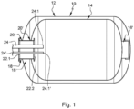
- a hydrogen tank 10 comprises an external enclosure 12, an internal enclosure 14 positioned in the external enclosure 12, thermal insulation between the external and internal enclosures 12, 14 and two diametrically opposed connecting systems 16, 16' connecting the external and internal enclosures 12, 14.
- the internal enclosure 14 may, depending on the situation, contract or expand more than the external enclosure 12. Consequently, at least one of the two connecting systems 16' is configured to allow movement of the internal enclosure 14 relative to the external enclosure 12 in a direction of movement.
- the first connecting system 16 (the one on the left in the Figure 1 ) is substantially rigid and does not allow any relative movement between the external and internal enclosures 12, 14 while a second connecting system 16' (the one on the right on the Figure 1 ) allows relative movement between the external and internal enclosures 12, 14.
- the first connection system 16 comprises a tubular interface 18 passing through the external and internal enclosures 12, 14 and having a first end 18.1 opening outside the external tank 12 and a second end 18.2 opening inside the internal tank 14, each of the external and internal enclosures 12, 14 comprising a through hole 12.1, 14.1 to allow the passage of the tubular interface 18.
- the first connection system 16 comprises a first rigid connection 20 connecting the tubular interface 18 and the external enclosure 12 as well as a second rigid connection 20' connecting the tubular interface 18 and the internal enclosure 14.
- one of the first and second connections 20, 20' comprises at least one flange comprising a first wing pressed against the external or internal enclosure 12, 14 and connected to the latter as well as a second wing pressed against the tubular interface 18 and connected to the latter.
- the first connection system 16 comprises a first closing plate 22.1 closing the first end 18.1 of the tubular interface 18 as well as a second closing plate 22.2 closing the second end 18.2 of the tubular interface 18.
- the hydrogen tank 10 comprises several conduits 24, 24' which pass through the first and second closure plates 22.1, 22.2 and each comprise a first end 24.1, 24.1' opening into the internal enclosure 14. All these conduits 24, 24' are rectilinear between the first and second closure plates 22.1, 22.2.
- Each of the first and second closure plates 22.1, 22.2 comprises, for each conduit 24, 24', an orifice 26 to allow the conduit 24, 24' to pass through said first or second closure plate 22.1, 22.2.
- each conduit 24, 24' is connected to the first or second closure plate 22.1, 22.2 by a weld bead 28 which connects the conduit 24, 24' to the first or second closure plate 22.1, 22.2 in a sealed manner around the entire perimeter of the conduit 24, 24'.
- the materials of the different elements may be different: for example metallic/composite.
- the subject of the invention is a tank comprising an external enclosure, an internal enclosure positioned in the external enclosure, first and second connecting systems connecting the external and internal enclosures, a first wall integral with or forming part of the external enclosure, a second wall integral with or forming part of the internal enclosure as well as at least one conduit passing through the first and second walls.
- the first and second walls comprise, for each conduit, respectively first and second orifices to allow the conduit to pass through them;
- the tank comprising, for each conduit, first and second rigid connections connecting the conduit and respectively the first and second walls, each conduit comprising an intermediate section located between the first and second walls.
- the intermediate section has a curved axis such that the intermediate section has an excess length between said first and second walls.
- the excess length of the intermediate section makes it possible to compensate for a dimensional variation between the first and second walls and to limit the stresses on the first and second connections in order to reduce the risks of damage to the conduits and said first and second connections.
- the intermediate section has an axis which follows a trajectory in the form of a circular helix.
- the first and second walls are substantially parallel to each other and angularly offset by approximately 180°.
- the invention also relates to an aircraft comprising at least one tank according to one of the preceding characteristics.
- a tank 30 comprises an external enclosure 32, an internal enclosure 34 positioned in the external enclosure 32 as well as two diametrically opposed connection systems 36, connecting the external and internal enclosures 32, 34.
- the tank 30 may comprise thermal insulation between the external and internal enclosures 32, 34.
- the first connecting system 36 is substantially rigid while the second connecting system (not shown) allows relative movement between the external and internal enclosures 32, 34.
- the second connecting system is configured to allow relative movement between the external and internal enclosures 32, 34, oriented in a longitudinal direction.
- an aircraft comprises at least one tank 30 used to store a fluid in a cryogenic state, such as hydrogen.
- a cryogenic state such as hydrogen
- the first connection system 36 comprises a tubular interface 38 passing through the external and internal enclosures 32, 34, connected to the latter and having a first end 38.1 opening outside the external enclosure 32 as well as a second end 38.2 opening into the interior of the internal enclosure 34, each of the external and internal enclosures 32, 34 comprising a through hole 32.1, 34.1 to allow the passage of the tubular interface 38.
- the tubular interface 38 has an axis of revolution A38 parallel to the longitudinal direction.
- the first connecting system 36 comprises, for the internal enclosure 34, two L-shaped flanges 40, 40' positioned on either side of the internal enclosure 34, each flange 40, 40' comprising a first wing 40.1, 40.1' pressed against the internal enclosure 34 and connected to the latter as well as a second wing 40.2, 40.2' pressed against the tubular interface 38 and connected to the latter.
- the first connecting system 36 also comprises, for the external enclosure 32, a flange 40 positioned outside the external enclosure 32, comprising a first wing 40.1 pressed against the external enclosure 32 and connected to the latter as well as a second wing 40.2 pressed against the tubular interface 38 and connected to the latter.
- the invention is not limited to this configuration for the connections between the tubular interface 38 and the external and internal enclosures 32, 34.
- the first connecting system 36 comprises a first closing plate 42.1 closing the first end 38.1 of the tubular interface 38 and a second closing plate 42.2 closing the second end 38.2 of the tubular interface 38.
- the tubular interface 38 comprises a first collar 44.1 at its first end 38.1 and a second collar 44.2 at its second end 38.2, each of the first and second collars 44.1, 44.2 having a contact face F44.1, F44.2, positioned in a transverse plane perpendicular to the axis of revolution A38, against which the corresponding closing plate 42.1, 42.2 is pressed.
- the invention is not limited to this embodiment for the tubular interface 38.
- the hydrogen tank 30 comprises at least one conduit 46 which passes through the first and second closure plates 42.1, 42.2 and has a first end 46.1 opening outside the external enclosure 32 as well as a second end 46.2 opening into the internal enclosure 32.
- the first closure plate 42.1 comprises a first orifice 48.1 to allow the conduit 46 to pass through said first closure plate 42.1.
- the reservoir 30 comprises a first connection 50.1 connecting the conduit 46 and the first closure plate 42.1.
- the second closure plate 42.2 comprises a second orifice 48.2 to allow the conduit 46 to pass through said second closure plate 42.2.
- the reservoir 30 comprises a second connection 50.2 connecting the conduit 46 and the second closure plate 42.2.
- the first and second connections 50.1, 50.2 are rigid connections. Each of them is a sealed connection ensuring a fluid seal between the conduit 46 and the first or second closure plate 42.1, 42.2.
- each of the first and second connections 50.1, 50.2 comprises at least one weld bead surrounding the conduit 46 and ensuring a seal between the latter and the closure plate 42.1, 42.2.
- the invention is not limited to this embodiment for the first and second rigid connections 50.1, 50.2.
- the first or second connection 50.1, 50.2 could be in the form of a flange.
- tubular interface 38 and the closure plates 42.1, 42.2 are not further described because they may be identical to those of the prior art.
- Each conduit 46 comprises an intermediate section 52 located between the first and second closing plates 42.1, 42.2.
- the intermediate section 52 has a curved axis A46.
- the axis A46 is not rectilinear between the first and second closure plates 42.1, 42.2 so that the intermediate section 52 of the conduit 46 has an excess length between said first and second closure plates 42.1, 42.2.
- This excess length corresponds to the difference in length between, on the one hand, the length of the intermediate section 52 considered along its curved axis A46 and, on the other hand, the distance between the closure plates 42.1 and 42.2 considered along the axis of revolution A38.
- the outer enclosure 34 and the first closure plate 42.1 are in contact with an environment at room temperature while the inner enclosure 34, the second closure plate 42.2 and the section of the conduit 46 located in the inner enclosure 34 are in contact with a fluid at a cryogenic temperature, significantly lower than the room temperature.
- This temperature difference causes deformations of unequal values for at least two elements among the inner and outer enclosures 32, 34, the conduit 46 as well as the first and second closure plates 42.1, 42.2. This tends to modify the spacing between the first and second closure plates 42.1, 42.2 at level of the first and second orifices 48.1, 48.2 and consequently to generate significant stresses in at least one of the aforementioned elements.
- the excess length of the intermediate section 52 of the conduit 46 makes it possible to compensate for this dimensional variation between the first and second closing plates 42.1, 42.2, to limit the stresses on the first and second connections 50.1, 50.2 and to reduce the risks of damage to said first and second connections 50.1, 50.2.
- the axis A46 of the intermediate section 52 follows a trajectory in the form of a circular helix at least between the first and second closure plates 42.1, 42.2.
- the first and second closure plates 42.1, 42.2 are substantially parallel to each other and angularly offset by approximately 180°. Consequently, if the first orifice 48.1 of the first closure plate 42.1 is located at 6 o'clock, as illustrated in the Figure 5 , the second hole 48.2 of the second closing plate 42.1 is located at 12 o'clock, as illustrated in the Figure 6 .
- the tank 30 comprises several conduits 46, 46', 46" which pass through the first and second closure plates 42.1, 42.2, each of them comprising an intermediate section 52, 52', 52" which has a curved axis A46, A46', A46” .
- all the intermediate sections 52, 52', 52" follow trajectories in the form of a circular helix having approximately the same helix axis, at least between the first and second closing plates 42.1, 42.2.
- the tank 30 comprises a first wall 42.1 integral with or forming part of the external enclosure 32, a second wall 42.2 integral with or forming part of the internal enclosure 34 as well as at least one conduit 46 passing through the first and second walls 42.1, 42.2.
- the first and second walls 42.1, 42.2 respectively comprise first and second orifices 48.1, 48.2 to allow the conduit 46 to pass through the first and second walls 42.1, 42.2.
- the reservoir 30 comprises, for each conduit 46, first and second rigid connections 50.1, 50.2 connecting the conduit 46 and respectively the first and second walls 42.1, 42.2.
Landscapes
- Engineering & Computer Science (AREA)
- Mechanical Engineering (AREA)
- General Engineering & Computer Science (AREA)
- Filling Or Discharging Of Gas Storage Vessels (AREA)
Claims (5)
- Tank, welcher ein äußeres Gehäuse (32), ein inneres Gehäuse (34), das in dem äußeren Gehäuse (32) positioniert ist, ein erstes und ein zweites Verbindungssystem (36), welche das äußere und das innere Gehäuse (32, 34) verbinden, eine erste Wand (42.1), die mit dem äußeren Gehäuse (32) fest verbunden oder dessen Bestandteil ist, eine zweite Wand (42.2), die mit dem inneren Gehäuse (34) fest verbunden oder dessen Bestandteil ist, sowie mindestens eine Leitung (46), welche die erste und die zweite Wand (42.1, 42.2) durchquert, umfasst; wobei die erste und die zweite Wand (42.1, 42.2) für jede Leitung (46) eine erste bzw. zweite Öffnung (48.1, 48.2) aufweisen, um zu ermöglichen, dass die Leitung (46) sie durchquert; wobei der Tank (30) für jede Leitung (46) eine erste und eine zweite starre Verbindung (50.1, 50.2) aufweist, welche die Leitung (46) und die erste bzw. zweite Wand (42.1, 42.2) verbinden; wobei jede Leitung (46) einen Zwischenabschnitt (52) aufweist, der sich zwischen der ersten und der zweiten Wand (42.1, 42.2) befindet;
wobei der Zwischenabschnitt (52) eine gekrümmte Achse (A46) aufweist, derart, dass der Zwischenabschnitt (52) eine Überlänge zwischen der ersten und der zweiten Wand (42.1, 42.2) aufweist; dadurch gekennzeichnet, dass der Zwischenabschnitt (52) eine Achse (A46) aufweist, die einer Trajektorie in Form einer kreisförmigen Schraubenlinie folgt. - Tank nach dem vorhergehenden Anspruch, dadurch gekennzeichnet, dass die erste und die zweite Wand (42.1, 42.2) im Wesentlichen parallel zueinander sind und winkelmäßig um ungefähr 180° versetzt sind.
- Tank nach einem der vorhergehenden Ansprüche, dadurch gekennzeichnet, dass der Tank mehrere Leitungen (46, 46', 46") umfasst, welche die erste und die zweite Wand (42.1, 42.2) durchqueren und Zwischenabschnitte (52, 52', 52") aufweisen, die Trajektorien in Form kreisförmiger Schraubenlinien folgen, die annähernd dieselbe Schraubenlinienachse aufweisen.
- Tank nach einem der vorhergehenden Ansprüche, dadurch gekennzeichnet, dass das erste Verbindungssystem umfasst:- eine rohrförmige Schnittstelle (38), welche das äußere und das innere Gehäuse (32, 34) durchquert, mit diesen Letzteren verbunden ist und ein erstes Ende (38.1), das außerhalb des äußeren Gehäuses (32) mündet, sowie ein zweites Ende (38.2), das im Inneren des inneren Gehäuses (34) mündet, aufweist,- eine erste Verschlussplatte, die das erste Ende (38.1) der rohrförmigen Schnittstelle (38) verschließt und die erste Wand (42.1) bildet,- eine zweite Verschlussplatte, die das zweite Ende (38.2) der rohrförmigen Schnittstelle (38) verschließt und die zweite Wand (42.2) bildet.
- Luftfahrzeug, welches mindestens einen Tank nach einem der vorhergehenden Ansprüche aufweist.
Applications Claiming Priority (1)
| Application Number | Priority Date | Filing Date | Title |
|---|---|---|---|
| FR2304308 | 2023-04-28 |
Publications (2)
| Publication Number | Publication Date |
|---|---|
| EP4455542A1 EP4455542A1 (de) | 2024-10-30 |
| EP4455542B1 true EP4455542B1 (de) | 2025-06-11 |
Family
ID=87554630
Family Applications (1)
| Application Number | Title | Priority Date | Filing Date |
|---|---|---|---|
| EP24167911.7A Active EP4455542B1 (de) | 2023-04-28 | 2024-03-29 | Tank mit innen- und aussenräumen sowie mindestens einer leitung, die diese gehäuse durchquert und eine gekrümmte bahn zwischen den gehäusen |
Country Status (2)
| Country | Link |
|---|---|
| US (1) | US20240360956A1 (de) |
| EP (1) | EP4455542B1 (de) |
Family Cites Families (8)
| Publication number | Priority date | Publication date | Assignee | Title |
|---|---|---|---|---|
| US2515836A (en) * | 1946-01-23 | 1950-07-18 | Linde Air Prod Co | Apparatus for holding and vaporizing liquefied gases |
| US3687176A (en) * | 1970-03-18 | 1972-08-29 | United Aircraft Prod | Phase separator |
| SU1502897A1 (ru) * | 1986-04-30 | 1989-08-23 | Особое конструкторско-технологическое бюро Физико-технического института низких температур АН УССР | Криогенный сосуд дл транспортировани |
| NL8801044A (nl) * | 1988-04-21 | 1989-11-16 | Kelpa Cryogenics B V | Transporttank voor bij lage temperatuur vloeibaar gemaakt gas. |
| CA2441775C (en) * | 2003-09-23 | 2004-09-28 | Westport Research Inc. | Container for holding a cryogenic fluid |
| CA2852451A1 (en) * | 2014-05-23 | 2015-11-23 | Westport Power Inc. | Cryogenic storage vessel support |
| FR3089596B1 (fr) * | 2018-12-11 | 2021-03-19 | Air Liquide | Dispositif de support et conteneur de stockage de gaz liquéfié |
| US20230321607A1 (en) * | 2020-08-17 | 2023-10-12 | InnoSpire Technologies GmbH | Monolithic Membrane Filters |
-
2024
- 2024-03-29 EP EP24167911.7A patent/EP4455542B1/de active Active
- 2024-04-24 US US18/644,966 patent/US20240360956A1/en active Pending
Also Published As
| Publication number | Publication date |
|---|---|
| US20240360956A1 (en) | 2024-10-31 |
| EP4455542A1 (de) | 2024-10-30 |
Similar Documents
| Publication | Publication Date | Title |
|---|---|---|
| WO2022157091A1 (fr) | Dispositif d'accouplement et de détachement d'urgence | |
| EP4215791B1 (de) | Vorrichtung zum verbinden zweier doppelwandleitungen und wasserstoffleitung mit dieser verbindungsvorrichtung | |
| EP0284466B1 (de) | Auspuffrohrverbindungsvorrichtung und mit dieser Vorrichtung ausgestatteter Verbrennungsmotor | |
| WO2013024218A1 (fr) | Cône d'éjection pour turboréacteur d'aéronef | |
| EP3117173B1 (de) | Anschlussvorrichtung für einen wärmetauscher und wärmetauscher mit der anschlussvorrichtung | |
| EP3301344B1 (de) | Anschlussvorrichtung, die eine flexible muffe zum sammeln einer flüssigkeit im falle eines lecks oder aussickerns umfasst | |
| EP4455542B1 (de) | Tank mit innen- und aussenräumen sowie mindestens einer leitung, die diese gehäuse durchquert und eine gekrümmte bahn zwischen den gehäusen | |
| FR3054613A1 (fr) | Repartiteur d'admission a echangeur de chaleur integre | |
| EP4462012B1 (de) | Tank mit innen- und aussenräumen sowie mindestens einer leitung, die mindestens eine verformbare verschlussplatte durchquert | |
| EP0687884A1 (de) | Hülle gegen Durchbiegung | |
| EP4455543B1 (de) | Tank mit innen- und aussenräumen sowie mindestens einer zweiteiligen rohrschnittstelle, die den innen- und aussenraum durchquert | |
| EP3814616B1 (de) | Leitvorrichtung in einer brennkammer | |
| EP4522908A1 (de) | Doppelwandiger flüssiggasspeichertank | |
| WO2020161197A2 (fr) | Elément d'isolation thermique et ensemble comprenant un tel élément | |
| EP4361492B1 (de) | Vorrichtung zur lagerung einer kryogenen flüssigkeit | |
| EP3581781A1 (de) | Antriebssystem eines luftfahrzeugs mit einer befestigten innenstruktur, die einen auslassschlitz aufweist | |
| WO2008152311A2 (fr) | Dispositif d'isolation d'un collecteur d'echappement | |
| EP2006631A1 (de) | Kollektorflansch für einen Wärmetauscher | |
| EP3584488A1 (de) | Kanalisation, die zwei leitungen umfasst, die über ein verbessertes anschlusssystem verbunden sind | |
| FR2886338A1 (fr) | Collecteur d'echappement a double paroi pour moteur a combustion interne | |
| FR3160396A1 (fr) | Réservoir comprenant au moins un système de liaison à lames de jonction périphériques reliant une structure intérieure et une enceinte, aéronef comportant au moins un tel réservoir | |
| WO2023194102A1 (fr) | Boîte froide et procédé de montage | |
| WO2006079732A1 (fr) | Element de ligne d'echappement equipe d'un turbocompresseur | |
| FR3109210A1 (fr) | Echangeur de chaleur, notamment pour vehicule automobile | |
| EP1611388A1 (de) | Gasdichte dichtung für eine verbindung zwischen zwei leitungen und die dichtung enthaltende verbindung zwischen zwei dichtungen |
Legal Events
| Date | Code | Title | Description |
|---|---|---|---|
| PUAI | Public reference made under article 153(3) epc to a published international application that has entered the european phase |
Free format text: ORIGINAL CODE: 0009012 |
|
| STAA | Information on the status of an ep patent application or granted ep patent |
Free format text: STATUS: REQUEST FOR EXAMINATION WAS MADE |
|
| 17P | Request for examination filed |
Effective date: 20240329 |
|
| AK | Designated contracting states |
Kind code of ref document: A1 Designated state(s): AL AT BE BG CH CY CZ DE DK EE ES FI FR GB GR HR HU IE IS IT LI LT LU LV MC ME MK MT NL NO PL PT RO RS SE SI SK SM TR |
|
| GRAP | Despatch of communication of intention to grant a patent |
Free format text: ORIGINAL CODE: EPIDOSNIGR1 |
|
| STAA | Information on the status of an ep patent application or granted ep patent |
Free format text: STATUS: GRANT OF PATENT IS INTENDED |
|
| INTG | Intention to grant announced |
Effective date: 20250115 |
|
| GRAS | Grant fee paid |
Free format text: ORIGINAL CODE: EPIDOSNIGR3 |
|
| RIN1 | Information on inventor provided before grant (corrected) |
Inventor name: MORETTI, LAURE Inventor name: MESIC, CHLOE Inventor name: TOUREILLE, NICOLAS |
|
| GRAA | (expected) grant |
Free format text: ORIGINAL CODE: 0009210 |
|
| STAA | Information on the status of an ep patent application or granted ep patent |
Free format text: STATUS: THE PATENT HAS BEEN GRANTED |
|
| AK | Designated contracting states |
Kind code of ref document: B1 Designated state(s): AL AT BE BG CH CY CZ DE DK EE ES FI FR GB GR HR HU IE IS IT LI LT LU LV MC ME MK MT NL NO PL PT RO RS SE SI SK SM TR |
|
| REG | Reference to a national code |
Ref country code: GB Ref legal event code: FG4D Free format text: NOT ENGLISH |
|
| REG | Reference to a national code |
Ref country code: CH Ref legal event code: EP |
|
| REG | Reference to a national code |
Ref country code: IE Ref legal event code: FG4D Free format text: LANGUAGE OF EP DOCUMENT: FRENCH |
|
| REG | Reference to a national code |
Ref country code: DE Ref legal event code: R096 Ref document number: 602024000192 Country of ref document: DE |
|
| PG25 | Lapsed in a contracting state [announced via postgrant information from national office to epo] |
Ref country code: FI Free format text: LAPSE BECAUSE OF FAILURE TO SUBMIT A TRANSLATION OF THE DESCRIPTION OR TO PAY THE FEE WITHIN THE PRESCRIBED TIME-LIMIT Effective date: 20250611 Ref country code: ES Free format text: LAPSE BECAUSE OF FAILURE TO SUBMIT A TRANSLATION OF THE DESCRIPTION OR TO PAY THE FEE WITHIN THE PRESCRIBED TIME-LIMIT Effective date: 20250611 |
|
| REG | Reference to a national code |
Ref country code: LT Ref legal event code: MG9D |
|
| PG25 | Lapsed in a contracting state [announced via postgrant information from national office to epo] |
Ref country code: GR Free format text: LAPSE BECAUSE OF FAILURE TO SUBMIT A TRANSLATION OF THE DESCRIPTION OR TO PAY THE FEE WITHIN THE PRESCRIBED TIME-LIMIT Effective date: 20250912 Ref country code: NO Free format text: LAPSE BECAUSE OF FAILURE TO SUBMIT A TRANSLATION OF THE DESCRIPTION OR TO PAY THE FEE WITHIN THE PRESCRIBED TIME-LIMIT Effective date: 20250911 |
|
| REG | Reference to a national code |
Ref country code: NL Ref legal event code: MP Effective date: 20250611 |
|
| PG25 | Lapsed in a contracting state [announced via postgrant information from national office to epo] |
Ref country code: BG Free format text: LAPSE BECAUSE OF FAILURE TO SUBMIT A TRANSLATION OF THE DESCRIPTION OR TO PAY THE FEE WITHIN THE PRESCRIBED TIME-LIMIT Effective date: 20250611 |
|
| PG25 | Lapsed in a contracting state [announced via postgrant information from national office to epo] |
Ref country code: HR Free format text: LAPSE BECAUSE OF FAILURE TO SUBMIT A TRANSLATION OF THE DESCRIPTION OR TO PAY THE FEE WITHIN THE PRESCRIBED TIME-LIMIT Effective date: 20250611 |
|
| PG25 | Lapsed in a contracting state [announced via postgrant information from national office to epo] |
Ref country code: RS Free format text: LAPSE BECAUSE OF FAILURE TO SUBMIT A TRANSLATION OF THE DESCRIPTION OR TO PAY THE FEE WITHIN THE PRESCRIBED TIME-LIMIT Effective date: 20250911 |
|
| PG25 | Lapsed in a contracting state [announced via postgrant information from national office to epo] |
Ref country code: LV Free format text: LAPSE BECAUSE OF FAILURE TO SUBMIT A TRANSLATION OF THE DESCRIPTION OR TO PAY THE FEE WITHIN THE PRESCRIBED TIME-LIMIT Effective date: 20250611 |
|
| PG25 | Lapsed in a contracting state [announced via postgrant information from national office to epo] |
Ref country code: NL Free format text: LAPSE BECAUSE OF FAILURE TO SUBMIT A TRANSLATION OF THE DESCRIPTION OR TO PAY THE FEE WITHIN THE PRESCRIBED TIME-LIMIT Effective date: 20250611 |
|
| PG25 | Lapsed in a contracting state [announced via postgrant information from national office to epo] |
Ref country code: PT Free format text: LAPSE BECAUSE OF FAILURE TO SUBMIT A TRANSLATION OF THE DESCRIPTION OR TO PAY THE FEE WITHIN THE PRESCRIBED TIME-LIMIT Effective date: 20251013 |
|
| REG | Reference to a national code |
Ref country code: AT Ref legal event code: MK05 Ref document number: 1802518 Country of ref document: AT Kind code of ref document: T Effective date: 20250611 |
|
| PG25 | Lapsed in a contracting state [announced via postgrant information from national office to epo] |
Ref country code: IS Free format text: LAPSE BECAUSE OF FAILURE TO SUBMIT A TRANSLATION OF THE DESCRIPTION OR TO PAY THE FEE WITHIN THE PRESCRIBED TIME-LIMIT Effective date: 20251011 |
|
| PG25 | Lapsed in a contracting state [announced via postgrant information from national office to epo] |
Ref country code: SM Free format text: LAPSE BECAUSE OF FAILURE TO SUBMIT A TRANSLATION OF THE DESCRIPTION OR TO PAY THE FEE WITHIN THE PRESCRIBED TIME-LIMIT Effective date: 20250611 Ref country code: AT Free format text: LAPSE BECAUSE OF FAILURE TO SUBMIT A TRANSLATION OF THE DESCRIPTION OR TO PAY THE FEE WITHIN THE PRESCRIBED TIME-LIMIT Effective date: 20250611 |
|
| PG25 | Lapsed in a contracting state [announced via postgrant information from national office to epo] |
Ref country code: CZ Free format text: LAPSE BECAUSE OF FAILURE TO SUBMIT A TRANSLATION OF THE DESCRIPTION OR TO PAY THE FEE WITHIN THE PRESCRIBED TIME-LIMIT Effective date: 20250611 |
|
| PG25 | Lapsed in a contracting state [announced via postgrant information from national office to epo] |
Ref country code: PL Free format text: LAPSE BECAUSE OF FAILURE TO SUBMIT A TRANSLATION OF THE DESCRIPTION OR TO PAY THE FEE WITHIN THE PRESCRIBED TIME-LIMIT Effective date: 20250611 |
|
| PG25 | Lapsed in a contracting state [announced via postgrant information from national office to epo] |
Ref country code: EE Free format text: LAPSE BECAUSE OF FAILURE TO SUBMIT A TRANSLATION OF THE DESCRIPTION OR TO PAY THE FEE WITHIN THE PRESCRIBED TIME-LIMIT Effective date: 20250611 |
|
| PG25 | Lapsed in a contracting state [announced via postgrant information from national office to epo] |
Ref country code: SK Free format text: LAPSE BECAUSE OF FAILURE TO SUBMIT A TRANSLATION OF THE DESCRIPTION OR TO PAY THE FEE WITHIN THE PRESCRIBED TIME-LIMIT Effective date: 20250611 |