EP4455448A2 - Leistungsturbinenwelle für einen entkoppelten gasgenerator - Google Patents
Leistungsturbinenwelle für einen entkoppelten gasgenerator Download PDFInfo
- Publication number
- EP4455448A2 EP4455448A2 EP24173140.5A EP24173140A EP4455448A2 EP 4455448 A2 EP4455448 A2 EP 4455448A2 EP 24173140 A EP24173140 A EP 24173140A EP 4455448 A2 EP4455448 A2 EP 4455448A2
- Authority
- EP
- European Patent Office
- Prior art keywords
- power turbine
- end portion
- shaft
- fan
- core engine
- Prior art date
- Legal status (The legal status is an assumption and is not a legal conclusion. Google has not performed a legal analysis and makes no representation as to the accuracy of the status listed.)
- Pending
Links
Images



Classifications
-
- B—PERFORMING OPERATIONS; TRANSPORTING
- B64—AIRCRAFT; AVIATION; COSMONAUTICS
- B64D—EQUIPMENT FOR FITTING IN OR TO AIRCRAFT; FLIGHT SUITS; PARACHUTES; ARRANGEMENT OR MOUNTING OF POWER PLANTS OR PROPULSION TRANSMISSIONS IN AIRCRAFT
- B64D35/00—Transmitting power from power plants to propellers or rotors; Arrangements of transmissions
- B64D35/02—Transmitting power from power plants to propellers or rotors; Arrangements of transmissions specially adapted for specific power plants
-
- F—MECHANICAL ENGINEERING; LIGHTING; HEATING; WEAPONS; BLASTING
- F01—MACHINES OR ENGINES IN GENERAL; ENGINE PLANTS IN GENERAL; STEAM ENGINES
- F01D—NON-POSITIVE DISPLACEMENT MACHINES OR ENGINES, e.g. STEAM TURBINES
- F01D5/00—Blades; Blade-carrying members; Heating, heat-insulating, cooling or antivibration means on the blades or the members
- F01D5/02—Blade-carrying members, e.g. rotors
- F01D5/026—Shaft to shaft connections
-
- B—PERFORMING OPERATIONS; TRANSPORTING
- B64—AIRCRAFT; AVIATION; COSMONAUTICS
- B64D—EQUIPMENT FOR FITTING IN OR TO AIRCRAFT; FLIGHT SUITS; PARACHUTES; ARRANGEMENT OR MOUNTING OF POWER PLANTS OR PROPULSION TRANSMISSIONS IN AIRCRAFT
- B64D27/00—Arrangement or mounting of power plants in aircraft; Aircraft characterised by the type or position of power plants
- B64D27/02—Aircraft characterised by the type or position of power plants
- B64D27/10—Aircraft characterised by the type or position of power plants of gas-turbine type
-
- F—MECHANICAL ENGINEERING; LIGHTING; HEATING; WEAPONS; BLASTING
- F01—MACHINES OR ENGINES IN GENERAL; ENGINE PLANTS IN GENERAL; STEAM ENGINES
- F01D—NON-POSITIVE DISPLACEMENT MACHINES OR ENGINES, e.g. STEAM TURBINES
- F01D5/00—Blades; Blade-carrying members; Heating, heat-insulating, cooling or antivibration means on the blades or the members
- F01D5/02—Blade-carrying members, e.g. rotors
-
- F—MECHANICAL ENGINEERING; LIGHTING; HEATING; WEAPONS; BLASTING
- F01—MACHINES OR ENGINES IN GENERAL; ENGINE PLANTS IN GENERAL; STEAM ENGINES
- F01D—NON-POSITIVE DISPLACEMENT MACHINES OR ENGINES, e.g. STEAM TURBINES
- F01D5/00—Blades; Blade-carrying members; Heating, heat-insulating, cooling or antivibration means on the blades or the members
- F01D5/02—Blade-carrying members, e.g. rotors
- F01D5/06—Rotors for more than one axial stage, e.g. of drum or multiple disc type; Details thereof, e.g. shafts, shaft connections
-
- F—MECHANICAL ENGINEERING; LIGHTING; HEATING; WEAPONS; BLASTING
- F01—MACHINES OR ENGINES IN GENERAL; ENGINE PLANTS IN GENERAL; STEAM ENGINES
- F01D—NON-POSITIVE DISPLACEMENT MACHINES OR ENGINES, e.g. STEAM TURBINES
- F01D5/00—Blades; Blade-carrying members; Heating, heat-insulating, cooling or antivibration means on the blades or the members
- F01D5/02—Blade-carrying members, e.g. rotors
- F01D5/10—Anti- vibration means
-
- F—MECHANICAL ENGINEERING; LIGHTING; HEATING; WEAPONS; BLASTING
- F02—COMBUSTION ENGINES; HOT-GAS OR COMBUSTION-PRODUCT ENGINE PLANTS
- F02C—GAS-TURBINE PLANTS; AIR INTAKES FOR JET-PROPULSION PLANTS; CONTROLLING FUEL SUPPLY IN AIR-BREATHING JET-PROPULSION PLANTS
- F02C3/00—Gas-turbine plants characterised by the use of combustion products as the working fluid
- F02C3/04—Gas-turbine plants characterised by the use of combustion products as the working fluid having a turbine driving a compressor
- F02C3/107—Gas-turbine plants characterised by the use of combustion products as the working fluid having a turbine driving a compressor with two or more rotors connected by power transmission
-
- F—MECHANICAL ENGINEERING; LIGHTING; HEATING; WEAPONS; BLASTING
- F02—COMBUSTION ENGINES; HOT-GAS OR COMBUSTION-PRODUCT ENGINE PLANTS
- F02C—GAS-TURBINE PLANTS; AIR INTAKES FOR JET-PROPULSION PLANTS; CONTROLLING FUEL SUPPLY IN AIR-BREATHING JET-PROPULSION PLANTS
- F02C7/00—Features, components parts, details or accessories, not provided for in, or of interest apart form groups F02C1/00 - F02C6/00; Air intakes for jet-propulsion plants
- F02C7/36—Power transmission arrangements between the different shafts of the gas turbine plant, or between the gas-turbine plant and the power user
-
- F—MECHANICAL ENGINEERING; LIGHTING; HEATING; WEAPONS; BLASTING
- F02—COMBUSTION ENGINES; HOT-GAS OR COMBUSTION-PRODUCT ENGINE PLANTS
- F02K—JET-PROPULSION PLANTS
- F02K3/00—Plants including a gas turbine driving a compressor or a ducted fan
- F02K3/02—Plants including a gas turbine driving a compressor or a ducted fan in which part of the working fluid by-passes the turbine and combustion chamber
- F02K3/04—Plants including a gas turbine driving a compressor or a ducted fan in which part of the working fluid by-passes the turbine and combustion chamber the plant including ducted fans, i.e. fans with high volume, low pressure outputs, for augmenting the jet thrust, e.g. of double-flow type
- F02K3/06—Plants including a gas turbine driving a compressor or a ducted fan in which part of the working fluid by-passes the turbine and combustion chamber the plant including ducted fans, i.e. fans with high volume, low pressure outputs, for augmenting the jet thrust, e.g. of double-flow type with front fan
-
- F—MECHANICAL ENGINEERING; LIGHTING; HEATING; WEAPONS; BLASTING
- F02—COMBUSTION ENGINES; HOT-GAS OR COMBUSTION-PRODUCT ENGINE PLANTS
- F02K—JET-PROPULSION PLANTS
- F02K3/00—Plants including a gas turbine driving a compressor or a ducted fan
- F02K3/02—Plants including a gas turbine driving a compressor or a ducted fan in which part of the working fluid by-passes the turbine and combustion chamber
- F02K3/04—Plants including a gas turbine driving a compressor or a ducted fan in which part of the working fluid by-passes the turbine and combustion chamber the plant including ducted fans, i.e. fans with high volume, low pressure outputs, for augmenting the jet thrust, e.g. of double-flow type
- F02K3/062—Plants including a gas turbine driving a compressor or a ducted fan in which part of the working fluid by-passes the turbine and combustion chamber the plant including ducted fans, i.e. fans with high volume, low pressure outputs, for augmenting the jet thrust, e.g. of double-flow type with aft fan
-
- F—MECHANICAL ENGINEERING; LIGHTING; HEATING; WEAPONS; BLASTING
- F02—COMBUSTION ENGINES; HOT-GAS OR COMBUSTION-PRODUCT ENGINE PLANTS
- F02K—JET-PROPULSION PLANTS
- F02K3/00—Plants including a gas turbine driving a compressor or a ducted fan
- F02K3/12—Plants including a gas turbine driving a compressor or a ducted fan characterised by having more than one gas turbine
-
- F—MECHANICAL ENGINEERING; LIGHTING; HEATING; WEAPONS; BLASTING
- F05—INDEXING SCHEMES RELATING TO ENGINES OR PUMPS IN VARIOUS SUBCLASSES OF CLASSES F01-F04
- F05D—INDEXING SCHEME FOR ASPECTS RELATING TO NON-POSITIVE-DISPLACEMENT MACHINES OR ENGINES, GAS-TURBINES OR JET-PROPULSION PLANTS
- F05D2240/00—Components
- F05D2240/60—Shafts
-
- F—MECHANICAL ENGINEERING; LIGHTING; HEATING; WEAPONS; BLASTING
- F05—INDEXING SCHEMES RELATING TO ENGINES OR PUMPS IN VARIOUS SUBCLASSES OF CLASSES F01-F04
- F05D—INDEXING SCHEME FOR ASPECTS RELATING TO NON-POSITIVE-DISPLACEMENT MACHINES OR ENGINES, GAS-TURBINES OR JET-PROPULSION PLANTS
- F05D2250/00—Geometry
- F05D2250/30—Arrangement of components
- F05D2250/31—Arrangement of components according to the direction of their main axis or their axis of rotation
- F05D2250/314—Arrangement of components according to the direction of their main axis or their axis of rotation the axes being inclined in relation to each other
-
- F—MECHANICAL ENGINEERING; LIGHTING; HEATING; WEAPONS; BLASTING
- F05—INDEXING SCHEMES RELATING TO ENGINES OR PUMPS IN VARIOUS SUBCLASSES OF CLASSES F01-F04
- F05D—INDEXING SCHEME FOR ASPECTS RELATING TO NON-POSITIVE-DISPLACEMENT MACHINES OR ENGINES, GAS-TURBINES OR JET-PROPULSION PLANTS
- F05D2260/00—Function
- F05D2260/40—Transmission of power
-
- F—MECHANICAL ENGINEERING; LIGHTING; HEATING; WEAPONS; BLASTING
- F05—INDEXING SCHEMES RELATING TO ENGINES OR PUMPS IN VARIOUS SUBCLASSES OF CLASSES F01-F04
- F05D—INDEXING SCHEME FOR ASPECTS RELATING TO NON-POSITIVE-DISPLACEMENT MACHINES OR ENGINES, GAS-TURBINES OR JET-PROPULSION PLANTS
- F05D2260/00—Function
- F05D2260/96—Preventing, counteracting or reducing vibration or noise
Definitions
- the present disclosure relates generally to turbine engine that includes a decoupled gas generator driving a propulsive fan and more particularly to a power turbine shaft coupling a gas generator to a propulsive fan.
- Gas turbine engines generally include a gas generating core engine that drives a propulsive fan through a nested shaft.
- the shaft driving the fan may be relatively long as compared to the overall engine structure. Rotor dynamic stability of long shafts can be challenging and require additional bearing structures. Additional bearing structures can complicate engine architectures and inhibit implementation of other desirable engine features.
- a propulsion system for an aircraft includes, among other possible things, a propulsor section that includes a fan with a plurality of fan blades that are rotatable about a fan axis, a core engine that is configured to generate a gas flow, a power turbine where the gas flow from the core engine is expanded to generate shaft power, and a power turbine shaft that is coupled between the power turbine and the propulsor section.
- the power turbine shaft is of an axial length between a first end portion (or first end) and a second end portion (or second end) along the fan axis that is greater than half a distance between a leading edge of the fan blades and a mechanical coupling of the power turbine shaft to the power turbine, and includes an outer diameter that increases in a direction away from each of the first end portion and the second end portion.
- the core engine is centered on a core axis that is inclined relative to the fan axis.
- the propulsor section is forward of the power turbine and the core engine is disposed aft of the power turbine.
- the power turbine shaft is unsupported between the first end portion and the second end portion.
- the propulsor section includes a fan drive gear system that is coupled to the power turbine shaft.
- a cross-sectional area transverse to a longitudinal length of the power turbine shaft is uniform between the first end portion and the second end portion.
- the cross-sectional area may be a material area.
- a ratio of a maximum radial wall thickness and a minimum radial wall thickness of the power turbine shaft is between 1.1 and 3.0.
- a center portion of the power turbine shaft is disposed between the first end portion and the second end portion includes a maximum outer diameter and a minimum wall thickness.
- a ratio of an outer diameter at the center portion to an inner diameter of a bearing assembly at either of the first end portion and the second end portion is between 1.25 and 5.00.
- the center portion is disposed an equal distance from each of the first end portion and the second end portion.
- the center portion is disposed at a location between 50% and 75% of a total length of the power turbine shaft.
- the center portion includes a constant outer diameter over a center axial distance.
- the propulsion system further includes a nacelle that surrounds the core engine and the fan section.
- the nacelle defines a bypass flow path through the nacelle and around the power turbine and the core engine.
- a propulsion system for an aircraft includes, among other possible things, a fan section that includes a fan drive gear system that drives a fan shaft supporting a plurality of fan blades about a fan axis, a core engine that defines a core flow path where air is compressed in a compressor section, communicated to a combustor section, mixed with fuel, and ignited to generate a gas flow that is expanded through a turbine section, a power turbine where the gas flow from the core engine is expanded to generate shaft power, and a power turbine shaft for transmitting torque from the power turbine to the fan drive gear system, the power turbine shaft is hollow and includes an outer diameter that increases in a direction away from each of a first end portion (or first end) and a second end portion (or second end) and is of an axial length between the first end portion and the second end portion along the fan axis that is greater than half a distance between a leading edge of the plurality of fan blades and a mechanical coupling to the power turbine.
- the power turbine shaft is unsupported between the first end portion and the second end portion.
- a cross-sectional area transverse to a longitudinal length of the power turbine shaft is uniform between the first end portion and the second end portion.
- the cross-sectional area may be a material area.
- a center portion of the power turbine shaft is disposed between the first end portion and the second end portion includes a maximum outer diameter and a minimum wall thickness.
- the core engine includes at least one shaft that couples the turbine section to the compressor section and the maximum diameter of the power turbine shaft is greater than any outer diameter of the at least one shaft of the core engine.
- a method of operating a gas turbine engine includes, among other possible things, generating a gas flow with a core engine that is disposed about a core engine axis that is inclined relative to a fan axis, generating shaft power to drive the fan having a plurality of fan blades with a power turbine that receives the gas flow from the core engine, and transmitting shaft power to a fan that is disposed about the fan axis through a power turbine shaft with an axial length along the fan axis that is greater than half a distance between a leading edge of the plurality of fan blades and a mechanical coupling to the power turbine.
- the power turbine shaft includes an outer diameter that increases in a direction away from each of a first end portion (or first end) and a second end portion (or second end) and/or has a 1st mode natural frequency that is at least 15% greater than a similar shaft with a uniform outer diameter.
- Figure 1 schematically illustrates an example propulsion system 20 with a gas generating core engine 22 spaced apart from a propulsive fan section 34. Decoupling from the fan section 34 provides for alternate locations of the core engine 22 and space within the nacelle 60 for additional components useful in alternate engine architectures.
- the core engine 22 is located aft of a power turbine 44. Shaft power generated by the power turbine is transmitted through a power turbine shaft 48 to drive a fan drive gear system 36.
- the spaced apart location of the core engine 22 results in a long power turbine shaft 48.
- Long, unsupported shafts may present rotor dynamic challenges that are not present in conventional engine architectures where the core engine 22 is mechanically coupled directly to the fan section 34.
- the example power turbine shaft 48 includes features that provide rotor dynamic stability without a centrally located bearing support structure.
- the core engine 22 defines a core flow path C through a compressor section 24 that communicates a pressurized airflow to a combustor section 26 where it is mixed with fuel from a fuel system 32 and ignited to generate an exhaust gas flow 30.
- the exhaust gas flow 30 expands through a turbine section 28 that is coupled through at least one shaft 35 to the compressor section 24.
- the exhaust gas flow 30 is then exhausted to the power turbine 44.
- the power turbine 44 is not mechanically coupled to core engine 22 and therefore rotates independent of the compressor section 24 and turbine section 28 of the core engine 22.
- the fuel system 32 is shown schematically and may provide a flow of a liquid hydrogen (LH 2 ) fuel to the core engine 22.
- LH 2 liquid hydrogen
- liquid hydrogen is described by way of example, other non-carbon based fuels, biofuels and sustainable aviation fuels could also be utilized and are within the scope and contemplation of this disclosure. Additionally, traditional carbon-based fuels could also be utilized and are within the contemplation and scope of this disclosure.
- the core engine 22 and the fan section 34 are disposed within a nacelle 60 that defines a bypass flow path B between an inlet 62 and exhaust outlet 64.
- the core engine 22 is at or past the exhaust outlet 64.
- the fan section 34 is disposed near the inlet 62.
- the example fan section 34 includes a plurality of fan blades 40 supported on a fan shaft 38 driven by the fan drive gear system 36.
- the fan drive gear system 36 is driven by the power turbine 44 through the power turbine shaft 48.
- the fan drive gear system 36 may be an epicycle gear train, such as a planetary gear system or other gear system, with a gear reduction ratio between about 2.5:1 and 5:1. It should be understood, however, that the above parameters are only exemplary of one embodiment of a fan drive gear system 36 and other gear system configurations may be utilized within the contemplation and scope of this disclosure.
- the power turbine shaft 48 is disposed along the fan axis A and includes a first end portion 52 coupled to the gear system 36 and a second end portion 54 that is coupled to the power turbine 44 by way of a coupling 46.
- the power turbine shaft 48 includes an axial length 50 that is equal to or greater than 1 ⁇ 2 an axial distance 58 between a leading edge 42 of the fan blades 40 and the coupling 46 to the power turbine 44.
- the power turbine shaft 48 extends the axial length 50 between a first bearing assembly 146 and a second bearing assembly 144.
- the first bearing assembly 142 is supported by a first support structure 146 and the second bearing assembly 144 is supported by a second support structure 150.
- the support structures 146, 150 are shown schematically and may be configured as portions of other static engine or nacelle cases, supports or structures.
- the bearing assemblies 142, 144 are provided with a lubricant flow 152 from a schematically shown engine lubrication system 154.
- the bearing assemblies 142, 144 may be configures as ball, roller, tapered or any combination of bearing structures compatible with the engine environment and shaft speeds.
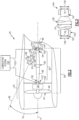
- FIG. 2 another example propulsion system 25 is shown schematically and includes an inclined gas generating core engine 66.
- the core engine 66 is disposed along a core engine axis 68 that is inclined at an angle 70 relative to the fan axis A.
- the angled orientation of the core engine axis 68 provides space for additional structures and systems within the nacelle 60 utilized for alternate propulsion system architectures. It should be understood that other engine architectures and core orientations could be utilized and are within the contemplation of this disclosure.
- Engine shafts utilized within the core engine are formed from metal alloys and compositions capable of withstanding extreme temperatures and loads encountered during turbine engine operation. Shafts within the core engine 22 are typically nested within each other and are subject to space and assembly limitations and constraints. For example, some shafts are nested within other shafts and therefore must be smaller and have substantially uniform diameters. The space constraint due to such a configuration places limits on all aspects of a core engine shaft including material selection, length, diameter, shape, and configuration of supportive bearing structures.
- the example power turbine shaft 48 is not disposed within the core engine 22 and therefore is free from constraints of turbine shafts utilized within a core engine.
- the example power turbine shaft 48 may be formed from metal alloys, light weight steel alloys or alternate composite materials. Alternate composite materials may include carbon fiber reinforced plastic or other advance composite materials.
- the example power turbine shaft 48 has a larger outer diameter than would be practical for shafts utilized within the core engine 22.
- the overall shape of power turbine shaft 48 including the larger center portion 56 is enabled by the disclosed engine architecture that includes the remote core engine 22 location.
- the center portion 56 and end portions 52, 54 are shown schematically.
- the end portions 52, 54 are shown with the corresponding bearing assembly 142, 144.
- Each of the first and second bearing assemblies 142, 144 have a corresponding inner diameter 148, 156.
- the inner diameters 142, 144 corresponding to respective ones of the first bearing assembly 142 and the second bearing assembly 144 may be different.
- both the first and second bearing assemblies 142, 144 have equal inner diameters 148, 156 within accepted standard tolerances.
- the inner diameters 148, 156 are between about 3.5 inches and 8.0 inches (88.9 mm and 203.2 mm).
- the inner diameters 148, 156 are between about 5.0 inches and 6.0 inches (127 mm and 152.4 mm).
- the inner diameters 148, 156 are diameters that correspond with the interface of each of the bearing assemblies 142, 144.
- the end portions 52 and 54 may have different diameters and configurations before and after the bearing configurations that correspond with coupling and attachment features such as splines interfaces. Accordingly, the inner diameters 148, 156 are reflective of diameters that correspond with an interface with the bearing assemblies 142, 144 within each of the end portions 52, 54 of the power turbine shaft 48.
- the center portion 56 includes a center outer diameter 74 that is greater than either a first end outer diameter 76 or a second end outer diameter 72.
- the larger outer diameter 74 increases stiffness of the power turbine shaft 48 and provides for operation and increased speeds.
- Increased operational shaft speeds are supported by the bearing assemblies 142, 144.
- the inner diameters 148, 156 of the bearing assemblies 142, 144 and the larger outer diameter 74 of the center portion 56 are structured to complement each other to enable the increased shaft speeds.
- the relationship between the outer diameter 74 in the center portion 56 is related to a maximum inner diameter to a maximum inner diameter of each bearing assembly
- the outer diameter 74 and a maximum bearing inner diameter 148, 156 of each of the bearing assemblies 148, 156 is related according to a defined ratio.
- the defined ratio accounts for the shaft speed, requires stiffness provided by the outer diameter 74 of the center portion and capabilities of the bearing assemblies 142, 144.
- the specific size of the outer diameter 74 and the inner diameters 148, 156 may be scaled depending on application specific parameters, it is appropriate to describe the relative diameters of the power turbine shaft 48 as a ratio.
- a ratio of the outer diameter 74 to either of the inner diameters 148, 156 of the bearing assemblies 142, 144 is between about 1.25 and 5.00. In another example embodiment, the ratio of the outer diameter 74 to the inner diameter 148, 156 is between about 1.5 and 2.5.
- the power turbine shaft 48 is a one-piece hollow part with a center portion 56 disposed between the first end portion 52 and the second end portion 54.
- the center portion 56 includes the center outer diameter 74 that is greater than either the first end outer diameter 76 or the second end outer diameter 72.
- An outer diameter 78 increases in a direction away from the corresponding end portion 52, 54 toward the center portion 56. Accordingly, the power turbine shaft 48 includes a bulged, larger center outer diameter 74 at the center portion 56.
- the center outer diameter 76 is the maximum outer diameter and is greater than any outer diameter of the at least one shaft 35 of the core engine 22.
- the larger center outer diameter 74 provides an increase in overall shaft stiffness that improves rotor dynamic stability.
- the center outer diameter 74 is uniform for an axial length 88.
- the axial length 88 is centered on a center point 90 of a total longitudinal length 95 of the power turbine shaft 48.
- the center point 90 is spaced an axial distance 92 from each end portion 52, 54.
- the outer diameter 78 expands uniformly over the axial distance 94 from either of the end portion 52, 54 to the center portion 56.
- the increased outer diameter at the center portion 56 provides increased stiffness that improves rotor dynamic response and provides a favorable higher natural frequency as compared to shafts with a single uniform outer diameter over the entire shaft length.
- the power turbine shaft 48 includes a 1 st mode natural frequency that is at least 15% greater than a similar shaft with a uniform outer diameter.
- a wall 80 of the power turbine shaft 48 changes thickness between the end portions 52, 54 and the center portion 56.
- the wall 80 decreases in thickness in a direction away from the end portions 52, 54 toward the center portion 56.
- the example end portions 52, 54 have a wall thickness 84 that is less than a wall thickness 82 within the center portion 56.
- the thickness 84 decreases uniformly along the axial length 94 toward the center portion 56. In the axial length 88, the wall thickness 82 remains constant.
- Each of the end portions 52, 54 may include splines 86 for coupling to the power turbine 44 and the fan drive gear system 36.
- the splined portions 86 may be of a different wall thickness than the wall thickness 84 to accommodate the spline features.
- a radial cross-section transverse to the axis A is shown through the center portion 56 ( Figure 7 ) and through the end portions 52, 54 ( Figure 8 ).
- the decreasing wall thickness provides a uniform material area over the changes in outer diameter. As the outer diameter increases, the wall thickness decreases to maintain a uniform material area across the length of the power turbine shaft 48.
- a ratio of a maximum radial wall thickness at the end portions 52, 54 to a minimum radial wall thickness at the center portion 56 of the power turbine shaft is between 1.1 and 3.0. In another disclosed example embodiment, the ratio of the maximum radial wall radial thickness at the end portions 52, 54 to the minimum radial wall thickness at the center portion of the power turbine shaft 48 is between 1.1 and 2.0. In another disclosed example embodiment, the ratio of the maximum radial wall radial thickness at the end portions 52, 54 to the minimum radial wall thickness at the center portion 56 of the power turbine shaft 48 is between 1.1 and 1.5.
- the thickness at the splines 86 does not correspond with the uniform area as the ends are adapted to provide the coupling to the power turbine 44 and the gear system 36.
- the material area is the area of an annulus between an outer radius and an inner radius.
- the example shaft 48 is shown and disclosed as a perfect circle and therefore the area is determined utilizing the formula ⁇ x (RO 2 - RI 2 ), where RO is the outer radius and RI is the inner radius.
- the area 96 of the center portion 56 is determined utilizing the outer radius 100 and inner radius 98.
- the area 102 in each of the end portions 52, 54 is determined using the outer radius 104 and the inner radius 106.
- the area 96 and the area 102 are equal along the axial length of the shaft 48 to provide for a common or uniform shear area. Accordingly, the material area determined in any two places along the shaft 48, except for the splined portions, are equal in the disclosed example power turbine shaft 48.
- FIG. 9 another example power turbine shaft 108 is schematically shown with an offset midway portion 110 disposed between first and second end portions 112, 114.
- the midway portion 110 includes an outer diameter 116 that is greater than an outer diameter 118 at either of the end portions 112, 114.
- a shaft wall 132 varies in thickness to maintain a common material area along the length of the shaft 108.
- the midway portion 110 is spaced unequal distances from the first and second end portions 112, 114.
- the midway portion 110 is spaced a first axial distance 122 from the first end portion 112 and a second axial distance 126 from the second end portion 114.
- the second axial distance 126 is greater than the first axial distance 122 in this example embodiment.
- the midway portion 110 is disposed at a location between 50% and 75% of a total length 140 of the power turbine shaft 108.
- the material area of the shaft wall 132 remains constant.
- the shaft wall 132 will decrease in thickness in proportion to an increase in the outer diameter. Accordingly, a thickness 134 decreases in a direction away from the second end portion 114 for the axial length 126.
- the thickness 136 is disposed within the axial distance 122 between the first end 112 and the midway portion 110.
- the thickness 136 decreases in a direction toward the midway portion 110.
- the midway portion 110 includes a thickness 138 that is uniform along the axial length 130 of the midway portion 110.
- the outer diameter 116 along with the wall thickness 138 in the midway portion 110 is constant within the axial length 130. Outside of the midway portion 110, the first wall thickness 134 and the second wall thickness 136 increase in a direction toward the corresponding one of the end portions 112, 114.
- first end portion 112 and the second end portion 114 are disclosed as having the same outer diameter 118, different outer diameters could be utilized at each end portion an remain within the contemplation and scope of this disclosure.
- An embodiment with different outer diameters at each of the end portions 112, 114 would also have different wall thicknesses to maintain equal material area along the length of the shaft 108.
- the midway portion 110 is offset closer to the first end 112 than to the second end 114.
- the midway portion 110 is centered about the point 128 that is spaced an axial distance 120 from the first end portion 112 and a distance 124 from the second end portion 114.
- the offset location of the midway portion 110 provides for tailoring the shaft to application specific requirements.
- the midway portion 110 may be located at different locations along the length of the shaft 108 and be closer to the second end portion 114 then to the first end portion 112.
- example power turbine shafts 48, 108 are shown and described by way of example, other configurations of shafts and diameters that maintain a uniform material area along the length are also possible within the scope and contemplation of this disclosure.
- the example disclosed propulsion system embodiments include a long power turbine shaft that enables increased axial distances between a power turbine and the fan section while maintaining rotor dynamic stability.
Landscapes
- Engineering & Computer Science (AREA)
- Mechanical Engineering (AREA)
- General Engineering & Computer Science (AREA)
- Chemical & Material Sciences (AREA)
- Combustion & Propulsion (AREA)
- Aviation & Aerospace Engineering (AREA)
- Structures Of Non-Positive Displacement Pumps (AREA)
- Connection Of Motors, Electrical Generators, Mechanical Devices, And The Like (AREA)
Applications Claiming Priority (1)
| Application Number | Priority Date | Filing Date | Title |
|---|---|---|---|
| US18/308,766 US12091183B1 (en) | 2023-04-28 | 2023-04-28 | Power turbine shaft for decoupled gas generator |
Publications (2)
| Publication Number | Publication Date |
|---|---|
| EP4455448A2 true EP4455448A2 (de) | 2024-10-30 |
| EP4455448A3 EP4455448A3 (de) | 2024-11-27 |
Family
ID=90924475
Family Applications (1)
| Application Number | Title | Priority Date | Filing Date |
|---|---|---|---|
| EP24173140.5A Pending EP4455448A3 (de) | 2023-04-28 | 2024-04-29 | Leistungsturbinenwelle für einen entkoppelten gasgenerator |
Country Status (2)
| Country | Link |
|---|---|
| US (1) | US12091183B1 (de) |
| EP (1) | EP4455448A3 (de) |
Family Cites Families (10)
| Publication number | Priority date | Publication date | Assignee | Title |
|---|---|---|---|---|
| US2380952A (en) | 1943-06-23 | 1945-08-07 | Clarence L Dewey | Propeller shaft |
| DE4011082A1 (de) | 1990-04-05 | 1991-10-10 | Gkn Automotive Ag | Antriebswelle |
| DE4027296A1 (de) | 1990-08-29 | 1992-03-12 | Gkn Automotive Ag | Antriebswelle mit zusatzmassen |
| US8955304B2 (en) * | 2012-02-10 | 2015-02-17 | United Technologies Corporation | Gas turbine engine with modular cores and propulsion unit |
| JP6137512B2 (ja) | 2012-11-08 | 2017-05-31 | デーナ、オータモウティヴ、システィムズ、グループ、エルエルシー | ドライブシャフト管を形成するための方法 |
| US9726112B2 (en) * | 2013-03-07 | 2017-08-08 | United Technologies Corporation | Reverse flow gas turbine engine airflow bypass |
| FR3010443B1 (fr) * | 2013-09-06 | 2017-12-22 | Snecma | Ensemble formant joint d'etancheite pour une turbomachine comportant un joint a brosse et au moins une lechette |
| US10415466B2 (en) * | 2014-10-27 | 2019-09-17 | United Technologies Corporation | Offset cores for gas turbine engines |
| US11724813B2 (en) * | 2021-05-24 | 2023-08-15 | General Electric Company | Midshaft rating for turbomachine engines |
| US20220373019A1 (en) * | 2021-05-24 | 2022-11-24 | General Electric Company | Midshaft rating for turbomachine engines |
-
2023
- 2023-04-28 US US18/308,766 patent/US12091183B1/en active Active
-
2024
- 2024-04-29 EP EP24173140.5A patent/EP4455448A3/de active Pending
Also Published As
| Publication number | Publication date |
|---|---|
| US12091183B1 (en) | 2024-09-17 |
| EP4455448A3 (de) | 2024-11-27 |
Similar Documents
| Publication | Publication Date | Title |
|---|---|---|
| US12359628B2 (en) | High power epicyclic gearbox and operation thereof | |
| US10914240B2 (en) | Gas turbine | |
| US10837370B1 (en) | Gas turbine engine including gearbox structure having stiffness | |
| EP3144487B1 (de) | Kopplung für einen getriebefan | |
| EP2597292B1 (de) | Turbomotorenarchitektur mit niederdruckverdichter zwischen den axiallagern der hochdruck-und niederdruck-rotoren | |
| US20180334964A1 (en) | Support assembly for a propeller shaft | |
| EP2565424A2 (de) | Drehmomentrahmen und asymmetrisches Gleitlager für ein Fan- Getriebesystem | |
| US20240295193A1 (en) | High power epicyclic gearbox and operation thereof | |
| US11802515B2 (en) | Aeronautic propulsion system with low leakage rate and improved propulsion efficiency | |
| US12221929B2 (en) | High power epicyclic gearbox and operation thereof | |
| US20200165981A1 (en) | Shaft component and method for producing a shaft component | |
| US10830154B1 (en) | Gas turbine engine having fan shaft stiffness ratio | |
| US11131209B2 (en) | Gas turbine | |
| US20220298976A1 (en) | Aircraft engine | |
| EP4455448A2 (de) | Leistungsturbinenwelle für einen entkoppelten gasgenerator | |
| US12297779B2 (en) | Geared gas turbine engine | |
| EP3587764A1 (de) | Gasturbine | |
| US12352314B2 (en) | Air turbine starter with bearing support structure | |
| US11486267B2 (en) | Rolling element device with jointly tiltable raceways | |
| CN114017186A (zh) | 带有偏移接口的空气启动器 | |
| EP4628715A1 (de) | Heckgetriebemotor mit wärmerückgewinnungssystem | |
| US11585277B2 (en) | Stiffened rotor shaft for a gas turbine engine | |
| US11852080B1 (en) | Gearbox assembly |
Legal Events
| Date | Code | Title | Description |
|---|---|---|---|
| PUAI | Public reference made under article 153(3) epc to a published international application that has entered the european phase |
Free format text: ORIGINAL CODE: 0009012 |
|
| STAA | Information on the status of an ep patent application or granted ep patent |
Free format text: STATUS: THE APPLICATION HAS BEEN PUBLISHED |
|
| PUAL | Search report despatched |
Free format text: ORIGINAL CODE: 0009013 |
|
| AK | Designated contracting states |
Kind code of ref document: A2 Designated state(s): AL AT BE BG CH CY CZ DE DK EE ES FI FR GB GR HR HU IE IS IT LI LT LU LV MC ME MK MT NL NO PL PT RO RS SE SI SK SM TR |
|
| AK | Designated contracting states |
Kind code of ref document: A3 Designated state(s): AL AT BE BG CH CY CZ DE DK EE ES FI FR GB GR HR HU IE IS IT LI LT LU LV MC ME MK MT NL NO PL PT RO RS SE SI SK SM TR |
|
| RIC1 | Information provided on ipc code assigned before grant |
Ipc: F02K 3/12 20060101ALI20241022BHEP Ipc: F02K 3/04 20060101ALI20241022BHEP Ipc: F02K 3/02 20060101ALI20241022BHEP Ipc: F02C 3/04 20060101ALI20241022BHEP Ipc: F01D 5/10 20060101ALI20241022BHEP Ipc: F01D 5/06 20060101ALI20241022BHEP Ipc: F02K 3/062 20060101ALI20241022BHEP Ipc: F02K 3/06 20060101ALI20241022BHEP Ipc: F02C 7/36 20060101ALI20241022BHEP Ipc: F02C 3/107 20060101ALI20241022BHEP Ipc: F01D 5/02 20060101AFI20241022BHEP |
|
| STAA | Information on the status of an ep patent application or granted ep patent |
Free format text: STATUS: REQUEST FOR EXAMINATION WAS MADE |
|
| 17P | Request for examination filed |
Effective date: 20250527 |