EP4455080A1 - Phosphorus-carbon composite material, phosphorus-carbon composite material production method, negative electrode active material, negative electrode for lithium secondary battery, and lithium secondary battery - Google Patents
Phosphorus-carbon composite material, phosphorus-carbon composite material production method, negative electrode active material, negative electrode for lithium secondary battery, and lithium secondary battery Download PDFInfo
- Publication number
- EP4455080A1 EP4455080A1 EP22911425.1A EP22911425A EP4455080A1 EP 4455080 A1 EP4455080 A1 EP 4455080A1 EP 22911425 A EP22911425 A EP 22911425A EP 4455080 A1 EP4455080 A1 EP 4455080A1
- Authority
- EP
- European Patent Office
- Prior art keywords
- phosphorus
- carbon
- composite material
- carbon composite
- negative electrode
- Prior art date
- Legal status (The legal status is an assumption and is not a legal conclusion. Google has not performed a legal analysis and makes no representation as to the accuracy of the status listed.)
- Pending
Links
Images


Classifications
-
- H—ELECTRICITY
- H01—ELECTRIC ELEMENTS
- H01M—PROCESSES OR MEANS, e.g. BATTERIES, FOR THE DIRECT CONVERSION OF CHEMICAL ENERGY INTO ELECTRICAL ENERGY
- H01M4/00—Electrodes
- H01M4/02—Electrodes composed of, or comprising, active material
- H01M4/36—Selection of substances as active materials, active masses, active liquids
- H01M4/362—Composites
- H01M4/366—Composites as layered products
-
- H—ELECTRICITY
- H01—ELECTRIC ELEMENTS
- H01M—PROCESSES OR MEANS, e.g. BATTERIES, FOR THE DIRECT CONVERSION OF CHEMICAL ENERGY INTO ELECTRICAL ENERGY
- H01M4/00—Electrodes
- H01M4/02—Electrodes composed of, or comprising, active material
- H01M4/13—Electrodes for accumulators with non-aqueous electrolyte, e.g. for lithium-accumulators; Processes of manufacture thereof
- H01M4/133—Electrodes based on carbonaceous material, e.g. graphite-intercalation compounds or CFx
-
- C—CHEMISTRY; METALLURGY
- C01—INORGANIC CHEMISTRY
- C01B—NON-METALLIC ELEMENTS; COMPOUNDS THEREOF; METALLOIDS OR COMPOUNDS THEREOF NOT COVERED BY SUBCLASS C01C
- C01B25/00—Phosphorus; Compounds thereof
-
- C—CHEMISTRY; METALLURGY
- C01—INORGANIC CHEMISTRY
- C01B—NON-METALLIC ELEMENTS; COMPOUNDS THEREOF; METALLOIDS OR COMPOUNDS THEREOF NOT COVERED BY SUBCLASS C01C
- C01B25/00—Phosphorus; Compounds thereof
- C01B25/02—Preparation of phosphorus
-
- H—ELECTRICITY
- H01—ELECTRIC ELEMENTS
- H01M—PROCESSES OR MEANS, e.g. BATTERIES, FOR THE DIRECT CONVERSION OF CHEMICAL ENERGY INTO ELECTRICAL ENERGY
- H01M10/00—Secondary cells; Manufacture thereof
- H01M10/05—Accumulators with non-aqueous electrolyte
- H01M10/052—Li-accumulators
-
- H—ELECTRICITY
- H01—ELECTRIC ELEMENTS
- H01M—PROCESSES OR MEANS, e.g. BATTERIES, FOR THE DIRECT CONVERSION OF CHEMICAL ENERGY INTO ELECTRICAL ENERGY
- H01M10/00—Secondary cells; Manufacture thereof
- H01M10/05—Accumulators with non-aqueous electrolyte
- H01M10/052—Li-accumulators
- H01M10/0525—Rocking-chair batteries, i.e. batteries with lithium insertion or intercalation in both electrodes; Lithium-ion batteries
-
- H—ELECTRICITY
- H01—ELECTRIC ELEMENTS
- H01M—PROCESSES OR MEANS, e.g. BATTERIES, FOR THE DIRECT CONVERSION OF CHEMICAL ENERGY INTO ELECTRICAL ENERGY
- H01M4/00—Electrodes
- H01M4/02—Electrodes composed of, or comprising, active material
- H01M4/13—Electrodes for accumulators with non-aqueous electrolyte, e.g. for lithium-accumulators; Processes of manufacture thereof
- H01M4/136—Electrodes based on inorganic compounds other than oxides or hydroxides, e.g. sulfides, selenides, tellurides, halogenides or LiCoFy
-
- H—ELECTRICITY
- H01—ELECTRIC ELEMENTS
- H01M—PROCESSES OR MEANS, e.g. BATTERIES, FOR THE DIRECT CONVERSION OF CHEMICAL ENERGY INTO ELECTRICAL ENERGY
- H01M4/00—Electrodes
- H01M4/02—Electrodes composed of, or comprising, active material
- H01M4/36—Selection of substances as active materials, active masses, active liquids
- H01M4/362—Composites
-
- H—ELECTRICITY
- H01—ELECTRIC ELEMENTS
- H01M—PROCESSES OR MEANS, e.g. BATTERIES, FOR THE DIRECT CONVERSION OF CHEMICAL ENERGY INTO ELECTRICAL ENERGY
- H01M4/00—Electrodes
- H01M4/02—Electrodes composed of, or comprising, active material
- H01M4/36—Selection of substances as active materials, active masses, active liquids
- H01M4/38—Selection of substances as active materials, active masses, active liquids of elements or alloys
-
- H—ELECTRICITY
- H01—ELECTRIC ELEMENTS
- H01M—PROCESSES OR MEANS, e.g. BATTERIES, FOR THE DIRECT CONVERSION OF CHEMICAL ENERGY INTO ELECTRICAL ENERGY
- H01M4/00—Electrodes
- H01M4/02—Electrodes composed of, or comprising, active material
- H01M4/36—Selection of substances as active materials, active masses, active liquids
- H01M4/58—Selection of substances as active materials, active masses, active liquids of inorganic compounds other than oxides or hydroxides, e.g. sulfides, selenides, tellurides, halogenides or LiCoFy; of polyanionic structures, e.g. phosphates, silicates or borates
- H01M4/583—Carbonaceous material, e.g. graphite-intercalation compounds or CFx
-
- H—ELECTRICITY
- H01—ELECTRIC ELEMENTS
- H01M—PROCESSES OR MEANS, e.g. BATTERIES, FOR THE DIRECT CONVERSION OF CHEMICAL ENERGY INTO ELECTRICAL ENERGY
- H01M4/00—Electrodes
- H01M4/02—Electrodes composed of, or comprising, active material
- H01M4/36—Selection of substances as active materials, active masses, active liquids
- H01M4/58—Selection of substances as active materials, active masses, active liquids of inorganic compounds other than oxides or hydroxides, e.g. sulfides, selenides, tellurides, halogenides or LiCoFy; of polyanionic structures, e.g. phosphates, silicates or borates
- H01M4/583—Carbonaceous material, e.g. graphite-intercalation compounds or CFx
- H01M4/587—Carbonaceous material, e.g. graphite-intercalation compounds or CFx for inserting or intercalating light metals
-
- H—ELECTRICITY
- H01—ELECTRIC ELEMENTS
- H01M—PROCESSES OR MEANS, e.g. BATTERIES, FOR THE DIRECT CONVERSION OF CHEMICAL ENERGY INTO ELECTRICAL ENERGY
- H01M4/00—Electrodes
- H01M4/02—Electrodes composed of, or comprising, active material
- H01M2004/021—Physical characteristics, e.g. porosity, surface area
-
- H—ELECTRICITY
- H01—ELECTRIC ELEMENTS
- H01M—PROCESSES OR MEANS, e.g. BATTERIES, FOR THE DIRECT CONVERSION OF CHEMICAL ENERGY INTO ELECTRICAL ENERGY
- H01M4/00—Electrodes
- H01M4/02—Electrodes composed of, or comprising, active material
- H01M2004/026—Electrodes composed of, or comprising, active material characterised by the polarity
- H01M2004/027—Negative electrodes
-
- Y—GENERAL TAGGING OF NEW TECHNOLOGICAL DEVELOPMENTS; GENERAL TAGGING OF CROSS-SECTIONAL TECHNOLOGIES SPANNING OVER SEVERAL SECTIONS OF THE IPC; TECHNICAL SUBJECTS COVERED BY FORMER USPC CROSS-REFERENCE ART COLLECTIONS [XRACs] AND DIGESTS
- Y02—TECHNOLOGIES OR APPLICATIONS FOR MITIGATION OR ADAPTATION AGAINST CLIMATE CHANGE
- Y02E—REDUCTION OF GREENHOUSE GAS [GHG] EMISSIONS, RELATED TO ENERGY GENERATION, TRANSMISSION OR DISTRIBUTION
- Y02E60/00—Enabling technologies; Technologies with a potential or indirect contribution to GHG emissions mitigation
- Y02E60/10—Energy storage using batteries
Definitions
- the present invention relates to a phosphorus-carbon composite material, a method of producing a phosphorus-carbon composite material, a negative electrode active material, a negative electrode for a lithium secondary battery, and a lithium secondary battery.
- a lithium secondary battery is used as a power source of small electronic devices such as mobile phones and notebook computers.
- the lithium secondary battery has also been put into practical use in medium or large power sources, such as for automobiles power storage, and the like.
- a negative electrode active material of the lithium secondary battery As a negative electrode active material of the lithium secondary battery, a carbon material is known.
- a negative electrode active material in which phosphorus is further contained in a carbon material for the purpose of improving battery performance has been known (for example, refer to Patent Document 1).
- the negative electrode active material described in Patent Document 1 since the negative electrode active material containing the carbon material further contains phosphorus, a negative electrode having excellent charge and discharge capacities can be obtained.
- Patent Document 1 Japanese Unexamined Patent Application, First Publication No. H11-67207
- the present invention has been made in view of such circumstances, and an object of the present invention is to provide a novel phosphorus-carbon composite material containing phosphorus and carbon.
- another object is to provide a method of producing a phosphorus-carbon composite material, which enables favorable production of such a novel phosphorus-carbon composite material.
- still another object is to provide a negative electrode active material containing such a novel phosphorus-carbon composite material, a negative electrode for a lithium secondary battery, and a lithium secondary battery.
- an aspect of the present invention includes the following aspects.
- a novel phosphorus-carbon composite material including phosphorus and carbon.
- a method of producing a phosphorus-carbon composite material which suitably enables the production of such a novel phosphorus-carbon composite material.
- a negative electrode active material including such a novel phosphorus-carbon composite material, a negative electrode for a lithium secondary battery, and a lithium secondary battery.
- FIGS. 1 to 6 a method of producing a phosphorus-carbon composite material, a negative electrode active material, a negative electrode for a lithium secondary battery, and a lithium secondary battery according to the present embodiment will be described with reference to FIGS. 1 to 6 .
- the dimensions and ratios of each constituent element are appropriately modified in order to make the drawings easier to see.
- a phosphorus-carbon composite material includes phosphorus atoms and carbon atoms.
- the "phosphorus-carbon composite material” may be simply referred to as "P-C material”.
- a content ratio of the phosphorus atoms in the P-C material is 10 mass% or more and 95 mass% or less.
- a content ratio of the carbon atoms in the P-C material is 5 mass% or more and 90 mass% or less.
- the "content ratio of a certain atom in the P-C material” means “the content ratio (mass%) of a certain atom when the entire P-C material is 100 mass%".
- a sum of the content ratio of the carbon atoms and the content ratio of the phosphorus atoms in the P-C material is 100 mass%. Even in the case where the P-C material consists of the carbon atoms and the phosphorus atoms, impurities that are inevitably mixed in from raw materials or production steps of the P-C material are allowed.
- the P-C material may have 60 mass% or more of the entire P-C material consist of the phosphorus atoms and the carbon atoms, and may further include elements other than the phosphorus atoms and the carbon atoms.
- Examples of the element other than the phosphorus atoms and the carbon atoms included in the P-C material include lithium, silicon, germanium, tin, aluminum, zinc, magnesium, transition metals, nitrogen, oxygen, fluorine, silicon, titanium, niobium, sulfur, and chlorine.
- the P-C material includes these elements
- a metal oxide, a composite metal oxide, a metal fluoride, a metal sulfide, a metal chloride, silicon oxide, silicate, titanate, or aluminate of these elements can be used as a raw material of the P-C material.
- the content ratio of the phosphorus atoms, the content ratio of the carbon atoms, and a content ratio of any other atoms which can be further included in the P-C material can be determined by known ICP analysis.
- the content ratio of the phosphorus atoms is preferably 20 mass% or more, more preferably 30 mass% or more, and still more preferably 50 mass% or more.
- a higher content ratio of phosphorus can increase initial charge and discharge capacities of the P-C material.
- the content ratio of the phosphorus atoms is preferably 90 mass% or less, more preferably 80 mass% or less, and still more preferably 75 mass% or less. The reason is that, in a case where the content ratio of the phosphorus atoms is too high, cycle characteristics of the P-C material deteriorate. An upper limit and a lower limit of the content ratio of the phosphorus atoms can be combined at will.
- the content ratio of the carbon atoms is preferably 10 mass% or more, more preferably 20 mass% or more, and still more preferably 25 mass% or more.
- a content ratio of the carbon atoms can enhance the cycle characteristics of the P-C material.
- the content ratio of the carbon atoms is preferably 80 mass% or less, more preferably 70 mass% or less, and still more preferably 50 mass% or less. This is because, in a case where the content ratio of the carbon atom is too high, the initial charge and discharge capacities of the P-C material decrease. An upper limit and a lower limit of the content ratio of the carbon atoms can be combined at will.
- the P-C material can be produced by performing ball mill mixing on phosphorus and a carbon material.
- the inventors conducted detailed analysis and examination on the obtained P-C material, and confirmed that the P-C material is not a mixture simply obtained by mixing phosphorus and the carbon material, which are raw materials, but is a novel material in which phosphorus atoms and carbon atoms are chemically bonded (covalently bonded) and provide physical properties different from those of phosphorus and the carbon material of the raw materials.
- P-C mixture the mixture of phosphorus and the carbon material
- the raw materials of the P-C material and the raw materials of the P-C mixture both contain black phosphorus and the carbon material in a ratio of 6:4 (mass ratio).
- CSCNT cup-stacked carbon nanotubes
- Other carbon materials that can be used as the raw material of the P-C material in addition to CSCNT will be described below.
- a ratio WL 620 /WL 780 of a weight loss ratio WL 620 at a measurement temperature of 620°C and a weight loss ratio WL 780 at a measurement temperature of 780°C which are obtained by thermogravimetric measurement under the following conditions, is 0.1 or more and 0.9 or less.
- 10 mg of the phosphorus-carbon composite material is accurately weighed to prepare a sample, and using a thermogravimetric measuring device, a weight change when the sample is heated from 50°C to 800°C at a temperature rising rate of 10 °C/min in a nitrogen stream is measured.
- a ratio of a weight of the sample at the measurement temperature to a weight of the accurately weighed sample is defined as a weight loss ratio (weight%) at the measurement temperature.
- weight loss ratio weight%
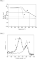
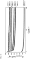
- FIG. 1 is a graph showing results of the above thermogravimetric measurement performed on the P-C material and the P-C mixture.
- FIG. 1 shows a heating temperature (°C) on a horizontal axis and the weight loss ratio (weight%) with respect to the weight of the sample on a vertical axis.
- reference sign A indicates a behavior of the P-C material
- reference sign X indicates a behavior of the P-C mixture.
- the weight loss ratio WL 620 (indicated by reference sign X1 in FIG. 1 ) at the measurement temperature of 620°C and the weight loss ratio WL 780 (indicated by reference sign X2 in FIG. 1 ) at the measurement temperature of 780°C are both less than 58%.
- the P-C mixture shows a steep weight loss at a measurement temperature of about 350°C to 450°C, and at 620°C, about 60% of the weight of the sample is lost from the initial weight.
- the ratio WL 620 /WL 780 between WL 620 and WL 780 is more than 0.9.
- the loss in weight in the thermogravimetric measurement of the P-C mixture is considered to correspond to a weight of black phosphorus, which is the raw material.
- black phosphorus included in the P-C mixture is lost by heating.
- black phosphorus is changed to red phosphorus, which is an allotrope of black phosphorus, when heated to 125°C.
- red phosphorus is sublimated at 416°C under normal pressure.
- the P-C material continues to lose weight from the measurement temperature of about 350°C until 800°C, which is an upper limit of a measurement temperature range, is reached.
- a weight loss is also observed between the measurement temperature of 620°C and the measurement temperature of 780°C.
- the ratio WL 620 /WL 780 of the weight loss ratio WL 620 (indicated by reference sign A1 in FIG. 1 ) at the measurement temperature of 620°C to the weight loss ratio WL 780 (indicated by reference sign A2 in FIG. 1 ) at the measurement temperature of 780°C is included in a range of 0.1 or more and 0.9 or less.
- a ratio WL 300 /WL 600 of a weight loss ratio WL 300 (indicated by reference sign A3 in FIG. 1 ) at a measurement temperature of 300°C to the weight loss ratio WL 600 (indicated by reference sign A4 in FIG. 1 ) at the measurement temperature of 600°C, which are obtained by the thermogravimetric measurement described above, is included in a range of -0.1 or more and 0.1 or less.
- the P-C material has no substantial weight loss up to the measurement temperature of 300°C, and is thermally stable at the measurement temperature of 300°C. Therefore, WL 300 is extremely small, and WL 300 /WL 600 is also a value near zero, that is, in a range of -0.1 or more and 0.1 or less.
- WL 620 /WL 780 is preferably 0.1 or more, more preferably 0.3 or more, and still more preferably 0.5 or more. In addition, WL 620 /WL 780 is preferably 0.9 or less and more preferably 0.8 or less. An upper limit and a lower limit of WL 620 /WL 780 may be combined at will.
- WL 300 /WL 600 is preferably -0.1 or more and more preferably -0.08 or more. In addition, WL 300 /WL 600 is preferably 0.1 or less and more preferably 0.08 or less. An upper limit and a lower limit of WL 300 /WL 600 may be combined at will.
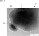
- the P-C material has a peak showing a bond between the phosphorus atom and the carbon atom in an XPS spectrum. It is known that the "peak showing the bond between the phosphorus atom and the carbon atom" appears in a range of 132 to 136 eV in the XPS spectrum. In the following description, the bond between the phosphorus atom and the carbon atom may be simply referred to as a "P-C bond".
- FIG. 2 shows XPS spectra of the P-C material and the P-C mixture.
- FIG. 2 shows a binding energy (eV) on a horizontal axis and the number of detected photoelectrons (counts per second (cps)) on a vertical axis.
- eV binding energy
- cps counts per second
- reference sign A indicates the P-C material
- reference sign X indicates the P-C mixture.
- the XPS spectrum is measured under the following measurement conditions.
- the obtained XPS spectrum may include noise in the analysis. Therefore, in the present embodiment, in a case where a line connecting two adjacent local minima in the XPS spectrum is set as a baseline, and a half-width of a local curve including a local maximum sandwiched between the two local minima is 0.5 eV or less, the curve is determined to be "noise". In a case where the presence or absence of the P-C bond is determined using the XPS spectrum, the presence or absence of a peak in the range of 132 to 136 eV is confirmed after excluding the "noise" according to the above definition.
- the P-C material is a material having chemical bonds between the phosphorus atoms and the carbon atoms.
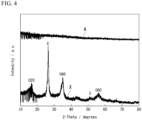
- the P-C material includes a core particle containing the phosphorus atom, and a carbon film covering a surface of the core particle.
- FIG. 3 is a transmission electron microscope (TEM) photograph of the P-C material.
- TEM transmission electron microscope
- EDX energy dispersive X-ray spectroscopy
- the phosphorus atom which is a heavier atom, appears darker in the TEM photograph. Therefore, based on the TEM photograph, the presence of the core-shell structure in which the phosphorus atom is included in the core particle 51 and is covered with the carbon film 52 including the carbon atom can be simply determined.
- the TEM photograph is taken under the following imaging conditions.
- the P-C material preferably has the above-described core-shell structure in addition to satisfying the requirements for [Behavior with Respect to Heat] described above.
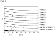
- FIG. 4 shows X-ray diffraction (XRD) profiles of the P-C material and the P-C mixture.
- FIG. 4 shows a diffraction angle (2 ⁇ , °) on a horizontal axis and a diffraction X-ray intensity (a.u.) on a vertical axis.
- the XRD profile indicated by reference sign A indicates the P-C material
- the XRD profile indicated by reference sign X indicates the P-C mixture.
- the XRD profile is measured under the following measurement conditions.
- each of the carbon material and black phosphorus has a certain crystallinity and shows a diffraction peak.
- the diffraction peaks observed in the P-C mixture is not observed, and only noise is confirmed in the entire measurement range. That is, from the results shown in FIG. 4 , it is considered that, in the P-C material, the carbon material used as the raw material either loses crystallinity and becomes amorphous, or has become a carbon material so fine that a crystalline state cannot be confirmed.
- P represented by Expression (2) above is a difference between the intensity I 40 at the reference point and the intensity I 26.3 at the position at which the peak of the carbon material is present, and indicates a difference in the peak from the reference point.
- the P-C material is a novel material that is different from the mixture obtained by mixing phosphorus (black phosphorus in FIGS. 1 to 4 ) and the carbon material as the raw materials in behavior with respect to heat, bonding state, external appearance, and crystalline state.
- the P-C material can be produced by a production method that includes a step of compositing the carbon material and phosphorus through a mixing and grinding process accompanied by compression.
- the carbon material which is the raw material at least one selected from the group consisting of amorphous carbon, graphite, porous carbon, mesocarbon microbeads (MCMB), fullerenes, carbon nanotubes, graphene, graphene oxide, carbon nitride (C 3 N 4 ), and layered carbon nanofibers (carbon nanofibers platelets) can be used. All of these carbon materials have a graphite structure.
- amorphous carbon examples include carbon black (CB), acetylene black (AB), Ketjen black, hard carbon, and soft carbon.
- Examples of the fullerenes include C 60 , C 72 , and C 84 .
- Examples of the carbon nanotubes include single-walled carbon nanotubes (SWCNT), multi-walled carbon nanotubes (MWCNT), cup-stacked carbon nanotubes (CSCNT), and carbon nanofiber vapor grown carbon fibers (VGCF). These have a structure (one-dimensional structure) extending in one axial direction.
- SWCNT single-walled carbon nanotubes
- MWCNT multi-walled carbon nanotubes
- CSCNT cup-stacked carbon nanotubes
- VGCF carbon nanofiber vapor grown carbon fibers
- the graphene, the graphene oxide, the carbon nitride (C 3 N 4 ), and the layered carbon nanofibers (carbon nanofibers platelets) have a structure (two-dimensional structure) that spreads in a planar direction.
- an end portion (edge site) of the graphite structure has a higher activity than portions other than the edge site because conjugation of sp 2 hybrid orbitals is interrupted. Therefore, it is assumed that most of the P-C bonds are formed at the edge sites of the carbon material. Therefore, from the viewpoint of facilitating the formation of the P-C bonds, it is considered that the carbon material to be used is preferably a material having many edge sites.
- Examples of the carbon material having many edge sites include CSCNT, graphite, mesocarbon microbeads (MCMB), graphene, graphene oxide, carbon nitride (C 3 N 4 ), and layered carbon nanofibers.
- CSCNT is preferable as the carbon material.
- any known phosphorus allotropes can be used as the raw phosphorus material.
- Phosphorus is preferably black phosphorus, which is the most chemically stable and a good conductor of electricity among the phosphorus allotropes.
- the "mixing and grinding process accompanied by compression” is a process of applying a compression force to a plurality of kinds of powder raw materials to mix and grind the raw materials. It is considered that, by performing the mixing and grinding process accompanied by compression on the carbon material and phosphorus, a strong impact force is applied to the carbon material and phosphorus, and thus a chemical change that cannot be obtained in a normal mixture occurs while the raw material powders are mixed and ground. As a result, it is considered that a P-C material in which a P-C bond that is not present in the raw material is formed and a crystalline state that is observed in the raw material is not observed is obtained as a product.
- the “mixing and grinding process accompanied by compression” may be performed until a peak derived from the raw material disappears in the XRD profile of the mixed material.
- the “mixing and grinding process accompanied by compression” may be performed until the occurrence of the P-C bond can be confirmed in the XPS spectrum of the mixed material.
- Examples of a processing device (grinder) capable of performing the mixing and grinding process accompanied by compression include a roller mill, a jet mill, a hammer mill, a pin mill, a disk mill, a rod mill, a ball mill, a vibratory mill, an attritor, and a beads mill.
- a roller mill a jet mill, a hammer mill, a pin mill, a disk mill, a rod mill, a ball mill, a vibratory mill, an attritor, and a beads mill.
- a stirred type grinder equipped with a grinding container and a rotating body, particularly from the viewpoint that mixing and grinding can be performed at the same time.
- Examples of the stirred type grinder include a pin mill, a disk mill, a rod mill, a ball mill, a vibratory mill, an attritor, and a beads mill.
- a medium-stirred type grinder is preferable because the raw material powders can be mixed and ground and a strong impact force can be applied to the carbon material and phosphorus at the same time.
- the medium-stirred type grinder include a ball mill, a vibratory mill, an attritor, and a beads mill.
- a ball mill is a particularly preferable grinder from the viewpoint that property conditions can be easily controlled.
- production conditions can be controlled by adjusting a rotation speed of a ball mill device, an amount of media (balls) with respect to the raw materials (ball powder ratio), and a mixing time. That is, by adjusting conditions such as increasing the rotation speed of the ball mill device, increasing the amount of media with respect to the raw materials, and increasing the mixing time, the mixing of phosphorus and the carbon material is promoted, and the P-C material is easily obtained.
- the generation of the P-C bond is promoted, and a P-C material satisfying a WL 620 /WL 780 of 0.1 or more and 0.9 or less is easily produced.
- Balls are grinding media for grinding a metal material.
- a diameter of the balls is an average particle diameter of the balls.
- the balls flow at a high speed in the grinding container by the rotation of the grinding container itself within the grinder, and collide with the powder raw materials including the carbon material and phosphorus, thereby grinding the powder raw materials into particles having a smaller average particle diameter. It is preferable that in a grinding step, the grinding container and beads are not excessively worn. Therefore, a shape of the ball is preferably spherical or ellipsoidal.
- the diameter of the balls is preferably larger than an average particle diameter of the P-C material after the grinding.
- a large grinding energy can be imparted to the metal material, so that it is possible to efficiently obtain metal particles within a short period of time.
- the diameter of the balls is too large, re-agglomeration of the P-C material is promoted, and the P-C material having a wide particle size distribution is generated.
- the diameter of the balls is preferably 0.1 to 10 mm and more preferably 1 to 10 mm. In a case where the diameter of the balls is within this range, the generation of the P-C bond can be promoted, and the re-agglomeration can be suppressed.
- the diameters of the balls to be put into the grinding container may be uniform or different from each other.
- Examples of a material of the ball include glass, agate, alumina, zirconia, stainless steel, chrome steel, tungsten carbide, silicon carbide, and silicon nitride.
- zirconia is preferable because of its relatively high hardness, which makes it resistant to wear, and of its relatively high specific gravity, which makes it possible to obtain a high grinding energy.
- a weight ratio of the balls to the raw material powders of the P-C material (a weight of the balls when a weight of the raw material powders of the P-C material is set to 1) is referred to as a ball-to-powder ratio.
- a ball-to-powder ratio By increasing the ball-to-powder ratio, a strong impact force can be imparted to the raw material powders of the P-C material at a high frequency, so that the generation of the P-C bond can be further promoted.
- the ball-to-powder ratio is too high, the amount of the P-C material produced per unit operation is reduced. Therefore, a preferable ball-to-powder ratio is 0.5 to 500, more preferably 1 to 200, and still more preferably 10 to 200.
- the balls are separated from the P-C material using a filter or the like.
- the fact that the above-described P-C material is obtained by the ball mill mixing can be confirmed by measuring an XRD profile of the mixed material and confirming that a peak derived from the raw material disappears as shown in FIG. 4 .
- a duration of the ball mill mixing may be determined by conducting a preliminary experiment on a correspondence between the mixing time and the time until the peak derived from the raw material disappears. In other words, the ball mill mixing may be performed until the peak derived from the raw material disappears in the XRD profile of the mixed material.
- the P-C material may be confirmed by measuring an XPS spectrum of the mixed material and observing the presence of the P-C bond as shown in FIG. 2 .
- the duration of the ball mill mixing may be determined by conducting a preliminary experiment on a correspondence between the mixing time and the time until the P-C bond is generated.
- the ball mill mixing may be performed until the generation of the P-C bond can be confirmed in the XPS spectrum of the mixed material.
- the carbon material or phosphorus is interposed between the media colliding with each other or between the media and the ball mill container, so that a strong local impact (pressure) is applied to the carbon material or phosphorus.
- a strong local impact pressure
- the details are not clear, but it is considered that, by applying such an impact, a chemical change that cannot be obtained in a normal mixture occurs, a P-C bond which is not present in the raw material is formed, and a P-C material that does not have the crystalline state observed in the raw materials is obtained.
- the above-described P-C material can be easily produced by performing the mixing and grinding process accompanied by compression on the carbon material and phosphorus.
- the above-described P-C material can be easily produced by a simple method of performing ball mill mixing on the carbon material and phosphorus.
- a negative electrode active material includes the above-described P-C material.
- the negative electrode active material may solely use the above-described P-C material, or may include a known material used as a negative electrode active material in addition to the P-C material.
- a material include (i) a carbon material capable of inserting and extracting lithium ions, (ii) an alloy-based negative electrode active material which involves the formation of a lithium alloy phase, (iii) a transition metal oxide which undergoes decomposition and regeneration reactions (conversion reactions) with lithium ions, and (iv) an oxide or a composite oxide which has an activity as a negative electrode material active material.
- Examples of (i) the carbon material include graphite, hard carbon, soft carbon, and carbon nanotubes.
- alloy-based negative electrode active material examples include a metal of silicon, germanium, tin, aluminum, zinc, or magnesium, or an alloy of these metals.
- transition metal oxide examples include a manganese oxide, an iron oxide, a cobalt oxide, a nickel oxide, a copper oxide, and a magnesium oxide. These oxides may be composite metal oxides further containing another metal (for example, lithium).
- Examples of (iv) the oxide or composite oxide include titanium oxide, lithium titanate, and silicon oxide.
- a negative electrode for a lithium secondary battery includes the above-described negative electrode active material.
- the negative electrode for a lithium secondary battery includes, in addition to the negative electrode active material, a current collector and a binder for binding the negative electrode active material to the current collector.
- the current collector and the binder can adopt a known configuration.
- copper or a copper alloy can be suitably used as a material of the current collector.
- PVdF polyvinylidene fluoride
- a lithium secondary battery includes the above-described negative electrode for a lithium secondary battery (hereinafter, negative electrode).
- An example of a lithium secondary battery that is suitable in a case where the above-described negative electrode active material is used has a positive electrode, a negative electrode, a separator interposed between the positive electrode and the negative electrode, and an electrolytic solution disposed between the positive electrode and the negative electrode.
- An example of the lithium secondary battery has a positive electrode, a negative electrode, a separator interposed between the positive electrode and the negative electrode, and an electrolytic solution disposed between the positive electrode and the negative electrode.
- FIG. 5 is a schematic view showing an example of the lithium secondary battery.
- a cylindrical lithium secondary battery 10 is produced as follows.
- a pair of separators 1 having a strip shape, a strip-shaped positive electrode 2 having a positive electrode lead 21 at one end, and a strip-shaped negative electrode 3 having a negative electrode lead 31 at one end are stacked in order of the separator 1, the positive electrode 2, the separator 1, and the negative electrode 3 and are wound to form an electrode group 4.
- the electrode group 4 and an insulator are accommodated in a battery can 5, a can bottom is then sealed, the electrode group 4 is impregnated with an electrolytic solution 6, and an electrolyte is disposed between the positive electrode 2 and the negative electrode 3. Furthermore, an upper portion of the battery can 5 is sealed with a top insulator 7 and a sealing body 8, whereby the lithium secondary battery 10 can be produced.
- Examples of a shape of the electrode group 4 include a columnar shape in which a cross-sectional shape when the electrode group 4 is cut in a direction perpendicular to a winding axis becomes a circle, an ellipse, a rectangle, or a rectangle with rounded corners.
- a shape defined by IEC60086 which is a standard for a battery defined by the International Electrotechnical Commission (IEC), or by JIS C 8500 can be adopted. Examples thereof include shapes such as a cylindrical shape or a square shape.
- the lithium secondary battery is not limited to the wound type configuration, and may have a stacked type configuration in which a stacked structure of a positive electrode, a separator, a negative electrode, and a separator is repeatedly stacked.
- a so-called coin type battery, a button type battery, and a paper type (or sheet type) battery are exemplary examples of the stacked type lithium secondary battery.
- the positive electrode can be produced by preparing a positive electrode mixture containing a positive electrode active material, a conductive material, and a binder, and supporting the positive electrode mixture by a positive electrode current collector.
- a lithium-containing compound or a compound containing another metal can be used as the positive electrode active material.
- the lithium-containing compound include a lithium cobalt composite oxide having a layered structure, a lithium nickel composite oxide having a layered structure, a lithium manganese composite oxide having a spinel structure, and a lithium iron phosphate having an olivine structure.
- Examples of the compound containing another metal include oxides such as titanium oxide, vanadium oxide, and manganese dioxide, and sulfides such as titanium sulfide and molybdenum sulfide.
- a carbon material As the conductive material included in the positive electrode, a carbon material can be used.
- the carbon material include graphite powder, carbon black (for example, acetylene black), and a fibrous carbon material.
- a proportion of the conductive material in the positive electrode mixture is preferably 5 to 20 parts by mass with respect to 100 parts by mass of the positive electrode active material.
- thermoplastic resin As the binder in the positive electrode, a thermoplastic resin can be used.
- the thermoplastic resin include a polyimide resin; a fluororesin such as polyvinylidene fluoride (PVdF) and polytetrafluoroethylene; and a polyolefin resin such as polyethylene and polypropylene and a resin described in WO2019/098384A1 or US2020/0274158A1 .
- a strip-shaped member formed of a metal material such as Al, Ni, or stainless steel as a forming material can be used.
- a method for supporting the positive electrode mixture by the positive electrode current collector a method in which a paste of the positive electrode mixture is prepared using an organic solvent, the obtained paste of the positive electrode mixture is applied to at least one surface side of the positive electrode current collector and dried, and the paste is fixed by performing an electrode pressing step is an exemplary example.
- NMP N-methyl-2-pyrrolidone
- Examples of a method of applying the paste of the positive electrode mixture to the positive electrode current collector include a slit die coating method, a screen coating method, a curtain coating method, a knife coating method, a gravure coating method, and an electrostatic spraying method.
- the positive electrode can be manufactured by the method mentioned above.
- the negative electrode included in the lithium secondary battery uses the negative electrode for a lithium secondary battery described above.
- a material that is made of a material such as a polyolefin resin such as polyethylene or polypropylene, a fluororesin, or a nitrogen-containing aromatic polymer and has a form such as a porous film, a non-woven fabric, or a woven fabric can be used.
- a separator described in JP-A-2000-030686 or US2009/0111025A1 may be used.
- the electrolytic solution included in the lithium secondary battery contains an electrolyte and an organic solvent.
- Examples of the electrolyte contained in the electrolytic solution include lithium salts such as LiClO 4 , LiPF 6 , LiAsF 6 , LiSbF 6 , LiBF 4 , LiCF 3 SO 3 , LiN(SO 2 CF 3 ) 2 , LiN(SO 2 C 2 F 5 ) 2 , LiN(SO 2 CF 3 )(COCF 3 ), Li(C 4 F 9 SO 3 ), LiC(SO 2 CF 3 ) 3 , Li 2 B 10 Cl 10 , LiBOB (here, BOB refers to bis(oxalato)borate), LiFSI (here, FSI refers to bis(fluorosulfonyl)imide), lower aliphatic carboxylic acid lithium salts, and LiAlCl 4 , and a mixture of two or more of these may be used.
- lithium salts such as LiClO 4 , LiPF 6 , LiAsF 6 , LiSbF 6 , LiBF 4
- the electrolyte it is preferable to use at least one selected from the group consisting of LiPF 6 , LiAsF 6 , LiSbF 6 , LiBF 4 , LiCF 3 SO 3 , LiN(SO 2 CF 3 ) 2 , and LiC(SO 2 CF 3 ) 3 , which contain fluorine.
- organic solvent that is contained in the electrolytic solution for example, carbonates such as propylene carbonate, ethylene carbonate, dimethyl carbonate, diethyl carbonate, ethyl methyl carbonate, 4-trifluoromethyl-1,3-dioxolan-2-one, and 1,2-di(methoxycarbonyloxy)ethane; ethers such as 1,2-dimethoxyethane, 1,3-dimethoxypropane, pentafluoropropyl methyl ether, 2,2,3,3-tetrafluoropropyl difluoromethyl ether, tetrahydrofuran, and 2-methyltetrahydrofuran; esters such as methyl formate, methyl acetate, propyl propionate, and ⁇ -butyrolactone; nitriles such as acetonitrile and butyronitrile; amides such as N,N-dimethylformamide and N,N-dimethylacetamide; carb
- the electrolytic solution may contain additives such as tris(trimethylsilyl) phosphate and tris(trimethylsilyl) borate.
- the organic solvent it is preferable to use a mixture of two or more thereof.
- a mixed solvent containing a carbonate is preferable, and a mixed solvent of a cyclic carbonate and a non-cyclic carbonate and a mixed solvent of a cyclic carbonate and an ether are more preferable.
- the electrolytic solution it is preferable to use an electrolytic solution containing a lithium salt containing fluorine such as LiPF 6 and an organic solvent having a fluorine substituent in order to enhance the safety of the obtained lithium secondary battery.
- a lithium salt containing fluorine such as LiPF 6
- an organic solvent having a fluorine substituent in order to enhance the safety of the obtained lithium secondary battery.
- the electrolyte and the organic solvent that are contained in the electrolytic solution the electrolytes and the organic solvents described in WO2019/098384A1 or US2020/0274158A1 may be used.
- FIG. 6 is a schematic view showing an example of the all-solid-state lithium secondary battery.
- An all-solid-state lithium secondary battery (lithium secondary battery) 1000 shown in FIG. 6 includes a laminate 100 including a positive electrode 110, a negative electrode 120, and a solid electrolyte layer 130, and an exterior body 200 that accommodates the laminate 100.
- the all-solid-state lithium secondary battery 1000 may have a bipolar structure in which a positive electrode active material and a negative electrode active material are disposed on both sides of a current collector.
- the bipolar structure for example, the structures described in JP-A-2004-95400 are exemplary examples. A material that configures each member will be described below.
- the laminate 100 may have an external terminal 113 that is connected to a positive electrode current collector 112 and an external terminal 123 that is connected to a negative electrode current collector 122.
- the all-solid-state lithium secondary battery 1000 may have a separator between the positive electrode 110 and the negative electrode 120.
- the all-solid-state lithium secondary battery 1000 further has an insulator (not shown) that insulates the laminate 100 and the exterior body 200 from each other and a sealant (not shown) that seals an opening portion 200a of the exterior body 200.
- a container formed of a highly corrosion-resistant metal material such as aluminum, stainless steel, or nickel-plated steel can be used as the exterior body 200.
- a container obtained by processing a laminate film having at least one surface subjected to a corrosion resistant process into a bag shape can also be used as the exterior body 200.
- Example of a shape of the all-solid-state lithium secondary battery 1000 include shapes such as a coin type, a button type, a paper type (or a sheet type), a cylindrical type, a square type, and a laminate type (pouch type).
- the all-solid-state lithium secondary battery 1000 may have a configuration in which the laminate 100 is used as a unit cell and a plurality of unit cells (laminates 100) is sealed inside the exterior body 200.
- the positive electrode 110 has a positive electrode active material layer 111 and the positive electrode current collector 112.
- the positive electrode active material layer 111 contains a positive electrode active material and a solid electrolyte.
- the positive electrode active material layer 111 may contain a conductive material and a binder.
- a solid electrolyte that has lithium ion conductivity and is used in well-known all-solid-state lithium secondary batteries can be adopted.
- the solid electrolyte include an inorganic electrolyte and an organic electrolyte.
- the inorganic electrolyte include an oxide-based solid electrolyte, a sulfide-based solid electrolyte, and a hydride-based solid electrolyte.
- the organic electrolyte include a polymer-based solid electrolyte.
- each electrolyte include the compounds described in WO 2020/208872A1 , US2016/0233510A1 , US2012/0251871A1 , and US2018/0159169A1 , and examples thereof include the following compounds.
- oxide-based solid electrolyte examples include a perovskite-type oxide, a NASICON-type oxide, a LISICON-type oxide, and a garnet-type oxide.
- specific examples of each oxide include the compounds described in WO 2020/208872A1 , US2016/0233510A1 , and US2020/0259213A1 , and examples thereof include the following compounds.
- perovskite-type oxide examples include Li-La-Ti-based oxides such as Li a La 1-a TiO 3 (0 ⁇ a ⁇ 1), Li-La-Ta-based oxides such as Li b La 1-b TaO 3 (0 ⁇ b ⁇ 1), and Li-La-Nb-based oxides such as Li c La 1-c NbO 3 (0 ⁇ c ⁇ 1).
- the NASICON-type oxide examples include Li 1+d Al d Ti 2-d (PO 4 ) 3 (0 ⁇ d ⁇ 1).
- the NASICON-type oxide is an oxide represented by Li m M 1 n M 2 o P p O q (in the formula, M 1 is one or more elements selected from the group consisting of B, Al, Ga, In, C, Si, Ge, Sn, Sb, and Se, M 2 is one or more elements selected from the group consisting of Ti, Zr, Ge, In, Ga, Sn, and Al, and m, n, o, p, and q areany positive numbers).
- LISICON-type oxide examples include an oxide represented by Li 4 M 3 O 4 -Li 3 M 4 O 4 (M 3 is one or more elements selected from the group consisting of Si, Ge, and Ti, and M 4 is one or more elements selected from the group consisting of P, As, and V).
- garnet-type oxide examples include an Li-La-Zr-based oxide such as Li 7 La 3 Zr 2 O 12 (also referred to as LLZ).
- the oxide-based solid electrolyte may be a crystalline material or an amorphous material.
- Examples of the sulfide-based solid electrolyte include Li 2 S-P 2 S 5 -based compounds, Li 2 S-SiS 2 -based compounds, Li 2 S-GeS 2 -based compounds, Li 2 S-B 2 S 3 -based compounds, LiI-Si 2 S-P 2 S 5 -based compounds, LiI-Li 2 S-P 2 O 5 -based compounds, LiI-Li 3 PO 4 -P 2 S 5 -based compounds, and Li 10 GeP 2 S 12 -based compounds.
- the expression "-based compound” indicating the sulfide-based solid electrolyte is used as a general term for solid electrolytes primarily containing raw materials such as "Li 2 S” and "P 2 S 5 " described before the "-based compound".
- the Li 2 S-P 2 S 5 -based compounds include solid electrolytes primarily containing Li 2 S and P 2 S 5 and further containing a different raw material.
- a proportion of Li 2 S that is contained in the Li 2 S-P 2 S 5 -based compound is, for example, 50 to 90 mass% with respect to the entire Li 2 S-P 2 S 5 -based compound.
- a proportion of P 2 S 5 that is contained in the Li 2 S-P 2 S 5 -based compound is, for example, 10 to 50 mass% with respect to the entire Li 2 S-P 2 S 5 -based compound.
- a proportion of the different raw material that is contained in the Li 2 S-P 2 S 5 -based compound is, for example, 0 to 30 mass% with respect to the entire Li 2 S-P 2 S 5 -based compound.
- the Li 2 S-P 2 S 5 -based compound also includes a solid electrolyte having a different mixing ratio of Li 2 S and P 2 S 5 .
- Li 2 S-P 2 S 5 -based compounds include Li 2 S-P 2 S 5 , Li 2 S-P 2 S 5 -LiI, Li 2 S-P 2 S 5 -LiCl, Li 2 S-P 2 S 5 -LiBr, Li 2 S-P 2 S 5 -LiI-LiBr, Li 2 S-P 2 S 5 -Li 2 O, Li 2 S-P 2 S 5 -Li 2 O-LiI, and Li 2 S-P 2 S 5 -Z m S n (m and n are positive numbers, and Z is Ge, Zn, or Ga).
- Li 2 S-SiS 2 -based compounds include Li 2 S-SiS 2 , Li 2 S-SiS 2 -LiI, Li 2 S-SiS 2 -LiBr, Li 2 S-SiS 2 -LiCl, Li 2 S-SiS 2 -B 2 S 3 -LiI, Li 2 S-SiS 2 -P 2 S 5 -LiI, Li 2 S-SiS 2 -P 2 S 5 -LiCl, Li 2 S-SiS 2 -Li 3 PO 4 , Li 2 S-SiS 2 -Li 2 SO 4 , and Li 2 S-SiS 2 -Li x MO y (x and y are positive numbers, and M is P, Si, Ge, B, Al, Ga, or In).
- Li 2 S-GeS 2 -based compounds examples include Li 2 S-GeS 2 and Li 2 S-GeS 2 -P 2 S 5 .
- the sulfide-based solid electrolyte may be a crystalline material or an amorphous material.
- Examples of a hydride-based solid electrolyte material include LiBH 4 , LiBH 4 -3KI, LiBH 4 -PI 2 , LiBH 4 -P 2 S 5 , LiBH 4 -LiNH 2 , 3LiBH 4 -LiI, LiNH 2 , Li 2 AlH 6 , Li(NH 2 ) 2 I, Li 2 NH, LiGd(BH 4 ) 3 Cl, Li 2 (BH 4 )(NH 2 ), Li 3 (NH 2 )I, and Li 4 (BH 4 )(NH 2 ) 3 .
- polymer-based solid electrolyte examples include organic polymer electrolytes such as polymer compounds containing one or more selected from the group consisting of a polyethylene oxide-based polymer compound, a polyorganosiloxane chain, and a polyoxyalkylene chain.
- organic polymer electrolytes such as polymer compounds containing one or more selected from the group consisting of a polyethylene oxide-based polymer compound, a polyorganosiloxane chain, and a polyoxyalkylene chain.
- gel type in which a non-aqueous electrolytic solution is held in a polymer compound can also be used.
- Two or more kinds of solid electrolytes can be used in combination as long as the effects of the invention are not impaired.
- the materials described in the above-described (conductive material) can be used.
- the proportion of the conductive material in the positive electrode mixture the proportions described in the above-described (conductive material) can be applied in the same manner.
- the binder that the positive electrode has the materials described in the above-described (binder) can be used.
- the materials described in the above-described can be used.
- Examples of a method for supporting the positive electrode active material layer 111 by the positive electrode current collector 112 include a method of pressure-molding the positive electrode active material layer 111 on the positive electrode current collector 112.
- a cold press or a hot press can be used for the pressure molding.
- the positive electrode active material layer 111 may be supported by the positive electrode current collector 112 by preparing a paste of a mixture of the positive electrode active material, the solid electrolyte, the conductive material, and the binder using an organic solvent to produce a positive electrode mixture, applying and drying the obtained positive electrode mixture on at least one surface of the positive electrode current collector 112, and fixing the positive electrode mixture by pressing.
- the positive electrode active material layer 111 may be supported by the positive electrode current collector 112 by preparing a paste of a mixture of the positive electrode active material, the solid electrolyte, and the conductive material using an organic solvent to produce a positive electrode mixture, applying and drying the obtained positive electrode mixture on at least one surface of the positive electrode current collector 112, and sintering the positive electrode mixture.
- the positive electrode active material that can be used for the positive electrode mixture the same material as the positive electrode active material described above in (Positive Electrode Active Material) can be used.
- the organic solvent that can be used for the positive electrode mixture the same organic solvent as the organic solvent that can be used in a case of preparing the paste of the positive electrode mixture described above in (Positive Electrode Current Collector) can be used.
- Examples of a method of applying the positive electrode mixture to the positive electrode current collector 112 include the methods described above in (Positive Electrode Current Collector).
- the positive electrode 110 can be produced by the methods mentioned above.
- Examples of a combination of specific materials that are used for the positive electrode 110 include combinations shown in Table 1 with the positive electrode active material.
- Table 1 Solid electrolyte Binder Conductive material Perovskite-type oxide Polyimide-based resin Graphite powder Carbon black Fibrous carbon material Fluororesin Graphite powder Carbon black Fibrous carbon material Polyolefin resin Graphite powder Carbon black Fibrous carbon material NASICON-type oxide Polyimide-based resin Graphite powder Carbon black Fibrous carbon material Fluororesin Graphite powder Carbon black Fibrous carbon material Polyolefin resin Graphite powder Carbon black Fibrous carbon material LISICON-type oxide Polyimide-based resin Graphite powder Carbon black Fibrous carbon material Fluororesin Graphite powder Carbon black Fibrous carbon material Polyolefin resin Graphite powder Carbon black Fibrous carbon material Garnet-type oxide Polyimide-based resin Graphite powder Carbon black Fibrous carbon material Fluororesin Graphite powder Carbon black
- the negative electrode 120 has a negative electrode active material layer 121 and the negative electrode current collector 122.
- the negative electrode active material layer 121 contains the negative electrode active material of the present embodiment.
- the solid electrolyte layer 130 has the above-described solid electrolyte.
- Examples of a method for producing the solid electrolyte layer 130 include a sputtering method in which an inorganic solid electrolyte is sputtered onto a surface of the positive electrode active material layer 111 included in the positive electrode 110 and a method of applying and drying a paste-form mixture containing a solid electrolyte.
- the solid electrolyte layer 130 may be formed by pressing the dried paste-form mixture and further pressurizing the paste-form mixture by a cold isostatic pressure method (CIP).
- CIP cold isostatic pressure method
- the laminate 100 can be produced by laminating the negative electrode 120 on the solid electrolyte layer 130 provided on the positive electrode 110 as described above using a well-known method in a form in which the negative electrode active material layer 121 is in contact with the surface of the solid electrolyte layer 130.
- the negative electrode active material including the above-described P-C material is used for the negative electrode. Therefore, a lithium battery having a high capacity and excellent cycle characteristics is achieved.
- the present invention also includes the following aspects.
- 10 mg of the phosphorus-carbon composite material is accurately weighed to prepare a sample, and using a thermogravimetric measuring device, a weight change when the sample is heated from 50°C to 780°C at a temperature rising rate of 10 °C/min in a nitrogen stream is measured.
- Imaging was performed according to (Imaging Conditions of TEM Photograph) described above.
- Black phosphorus and the carbon material were weighed in the ratios shown in Table 4 (total amount 0.5 g), and mixed using a ball mill under the following conditions to obtain P-C materials.
- evaluation batteries were produced by the following method, and evaluation was performed.
- the evaluation results are shown in Table 5.
- the materials used are as follows.
- the above-described mixture and a solvent (N-methyl-2-pyrrolidone (NMP)) were kneaded using an agate mortar to prepare a negative electrode slurry.
- NMP N-methyl-2-pyrrolidone
- a slurry concentration was adjusted to set a content ratio of the negative electrode active material (sum of the P-C material or the P-C mixture, the conductive material, and the binder) in the negative electrode slurry to 30% to 60 mass%.
- the negative electrode slurry was applied onto a copper foil current collector using a doctor blade, and then air-dried at 120°C for 1 hour to remove the solvent, thereby obtaining a laminate.
- the obtained laminate was pressed at a pressure of 10 mPa for 10 seconds and then further vacuum-dried at 120°C for 12 hours to obtain a negative electrode.
- the preparation of the negative electrode slurry and the preparation of the negative electrode described above were performed in a glove box with an argon atmosphere.
- a lithium-ion secondary battery (coin type battery R2032) was produced by combining the negative electrode produced in (1), a counter electrode, an electrolytic solution, and a separator. The battery was assembled in a glove box with an argon atmosphere.
- a metal lithium foil was used as the counter electrode.
- electrolytic solution a mixed solution obtained by adding 10 mass% of fluoroethylene carbonate (FEC) to a LiPF 6 solution (manufactured by Kishida Chemical Co., Ltd.) was used.
- FEC fluoroethylene carbonate
- LiPF 6 solution a solution obtained by dissolving LiPF 6 in a mixed solvent in which ethylene carbonate (EC), diethyl carbonate (DEC), and ethyl methyl carbonate (EMC) were mixed in a volume ratio of 30:35:35 such that a concentration of LiPF 6 was 1 mol/L was used.
- EC ethylene carbonate
- DEC diethyl carbonate
- EMC ethyl methyl carbonate
- a laminated film separator (16 ⁇ m thick) in which a heatresistant porous layer was laminated on a polyethylene porous film was used.
- a charge/discharge test was conducted under the following conditions at 25°C.
- a theoretical capacity of phosphorus was set to 2600 mAh/g
- a 1C current at which an electrode capacity was charged or discharged for 1 hour was set to 2600 mAh/g.
- the 1C current was calculated from the mass of phosphorus included in the negative electrode.
- cycle characteristics were evaluated by repeating charging and discharging under the following conditions while held at 25°C. Cycle characteristics were evaluated using a ratio (D100/D1) of a discharge capacity D 100 in a 100th cycle at a 1C-rate current to a charge capacity D 1 in a first cycle. The larger D100/D1 is, the higher a retention ratio of the discharge capacity over the cycles is, so that it can be determined that the negative electrode active material is excellent.
- FIG. 7 is a graph showing the results of the thermogravimetric measurement of the P-C materials produced in Examples 1 and 4 to 7 and the P-C mixture produced in Comparative Example 2. As shown in FIG. 7 , all of the P-C materials satisfied a WL 620 /WL 780 of 0. 1 or more and 0.9 or less.
- the P-C material of Example 7 had a WL 620 /WL 780 of 0.75, which was larger than that of the P-C materials of the other examples. It is considered that SWCNT, which is the carbon material used in Example 7, has a smaller amount of edge sites with respect to the amount of carbon atoms than other carbon materials. In such a carbon material having fewer edge sites, it is considered that the amount of P-C bonds generated is smaller than that in the carbon material having many edge sites. It is considered that such a difference in the amount of P-C bonds is shown as a difference in the results of the thermogravimetric measurement between the P-C material of Example 7 and the P-C materials of the other examples.
- the P-C mixtures of Comparative Examples 1 and 2 had a WL 620 /WL 780 of more than 0.9, showed a steep weight loss at a measurement temperature of about 350°C to 450°C, and showed almost no weight loss at a temperature of 500°C or higher. Therefore, it can be said that the P-C mixtures of Comparative Examples 1 and 2 did not form new bonds capable of withstanding a temperature as high as 620°C or higher and were in a state of a mixture of phosphorus and the carbon material as the raw materials. For WL 300 /WL 600 , both measurement samples satisfied -0.1 or more and 0.1 or less.
- FIG. 8 shows XPS spectra of the P-C materials produced in Examples 1 to 5 and 7. As shown in FIG. 8 , a peak had occurred in a range of 132 to 136 eV in all of the P-C materials, so that the formation of P-C bonds could be confirmed. A peak was observed in a range of 132 to 136 eV also in the P-C material of Example 6.
- FIG. 10 is a graph showing discharge capacities of the lithium secondary batteries using the P-C materials of Examples 1 to 7 and Comparative Example 2 up to 100 cycles. Evaluation of battery performance showed that the P-C materials of Examples 1 to 7 had a high discharge capacity and excellent cycle characteristics when used as a negative electrode active material. In contrast, the P-C mixture of Comparative Example 2 did not obtain a sufficient discharge capacity and had extremely low cycle characteristics compared to those of the examples.
Landscapes
- Chemical & Material Sciences (AREA)
- Chemical Kinetics & Catalysis (AREA)
- Electrochemistry (AREA)
- General Chemical & Material Sciences (AREA)
- Engineering & Computer Science (AREA)
- Inorganic Chemistry (AREA)
- Composite Materials (AREA)
- Materials Engineering (AREA)
- Organic Chemistry (AREA)
- Manufacturing & Machinery (AREA)
- Battery Electrode And Active Subsutance (AREA)
Abstract
Description
- The present invention relates to a phosphorus-carbon composite material, a method of producing a phosphorus-carbon composite material, a negative electrode active material, a negative electrode for a lithium secondary battery, and a lithium secondary battery.
- Priority is claimed on
Japanese Patent Application No. 2021-211116, filed on December 24, 2021 - A lithium secondary battery is used as a power source of small electronic devices such as mobile phones and notebook computers. In recent years, the lithium secondary battery has also been put into practical use in medium or large power sources, such as for automobiles power storage, and the like.
- As a negative electrode active material of the lithium secondary battery, a carbon material is known. In the related art, a negative electrode active material in which phosphorus is further contained in a carbon material for the purpose of improving battery performance has been known (for example, refer to Patent Document 1). In the negative electrode active material described in
Patent Document 1, since the negative electrode active material containing the carbon material further contains phosphorus, a negative electrode having excellent charge and discharge capacities can be obtained. - [Patent Document 1]
Japanese Unexamined Patent Application, First Publication No. H11-67207 - In order to obtain a lithium secondary battery having high reliability and high performance, as the negative electrode active material, a material having excellent durability in addition to charge and discharge capacities is required. There is still room for improvement in the negative electrode active material in the related art in order to improve the performance of the lithium secondary battery.
- The present invention has been made in view of such circumstances, and an object of the present invention is to provide a novel phosphorus-carbon composite material containing phosphorus and carbon. In addition, another object is to provide a method of producing a phosphorus-carbon composite material, which enables favorable production of such a novel phosphorus-carbon composite material. Furthermore, still another object is to provide a negative electrode active material containing such a novel phosphorus-carbon composite material, a negative electrode for a lithium secondary battery, and a lithium secondary battery.
- In order to achieve the above objects, an aspect of the present invention includes the following aspects.
- [1] A phosphorus-carbon composite material including: phosphorus atoms; and carbon atoms, in which a content ratio of the phosphorus atoms in the phosphorus-carbon composite material is 10 mass% or more and 95 mass% or less, a content ratio of the carbon atoms in the phosphorus-carbon composite material is 5 mass% or more and 90 mass% or less, and a ratio WL620/WL780 of a weight loss ratio WL620 at a measurement temperature of 620°C and a weight loss ratio WL780 at a measurement temperature of 780°C, which are obtained by thermogravimetric measurement under the following conditions, is 0.1 or more and 0.9 or less, in which
- (thermogravimetric measurement)
- 10 mg of the phosphorus-carbon composite material is accurately weighed to prepare a sample, and using a thermogravimetric measuring device, a weight change when the sample is heated from 50°C to 780°C at a temperature rising rate of 10 °C/min in a nitrogen stream is measured, and
- (weight loss ratio)
- a ratio of a weight of the sample at the measurement temperature to a weight of the accurately weighed sample is defined as a weight loss ratio (weight%) at the measurement temperature.
- [2] The phosphorus-carbon composite material according to [1], in which a ratio WL300/WL600 of a weight loss ratio WL300 at a measurement temperature of 300°C and a weight loss ratio WL600 at a measurement temperature of 600°C, which are obtained by the thermogravimetric measurement, is -0.1 or more and 0.1 or less.
- [3] The phosphorus-carbon composite material according to [1] or [2], in which in an XPS spectrum, a peak indicating a bond between a phosphorus atom and a carbon atom is present.
- [4] The phosphorus-carbon composite material according to any one of [1] to [3], in which, in an XRD profile measured using CuKα radiation, an intensity I20 at 20 = 20°, an intensity I26.3 at 20 = 26.3°, and an intensity I40 at 20 = 40° satisfy Expressions (1) to (3) below,



- [5] The phosphorus-carbon composite material according to any one of [1] to [4], in which the phosphorus-carbon composite material includes a core particle containing phosphorus atoms and a carbon film covering a surface of the core particle.
- [6] A method of producing a phosphorus-carbon composite material, the method including: a step of compositing a carbon material and phosphorus by a mixing and grinding process accompanied by compression.
- [7] A method of producing a phosphorus-carbon composite material, the method including: a step of performing ball mill mixing on a carbon material and phosphorus.
- [8] The method of producing a phosphorus-carbon composite material according to [6] or [7], in which the carbon material is at least one selected from the group consisting of amorphous carbon, graphite, porous carbon, a mesocarbon microbead, a fullerene, a carbon nanotube, graphene, graphene oxide, carbon nitride (C3N4), and a layered carbon nanofiber.
- [9] The method of producing a phosphorus-carbon composite material according to any one of [6] to [8], in which the phosphorus is black phosphorus.
- [10] A negative electrode active material including: the phosphorus-carbon composite material according to any one of [1] to [5].
- [11] A negative electrode for a lithium secondary battery, including: the negative electrode active material according to [10].
- [12] A lithium secondary battery including: the negative electrode for a lithium secondary battery according to [11].
- According to the present invention, it is possible to provide a novel phosphorus-carbon composite material including phosphorus and carbon. In addition, it is possible to provide a method of producing a phosphorus-carbon composite material, which suitably enables the production of such a novel phosphorus-carbon composite material. Furthermore, it is possible to provide a negative electrode active material including such a novel phosphorus-carbon composite material, a negative electrode for a lithium secondary battery, and a lithium secondary battery.
-
-
FIG. 1 is a graph showing results of thermogravimetric measurement performed on a P-C material and a P-C mixture. -
FIG. 2 shows XPS spectra of the P-C material and the P-C mixture. -
FIG. 3 is a transmission electron microscope (TEM) photograph of the P-C material. -
FIG. 4 shows XRD profiles of the P-C material and the P-C mixture. -
FIG. 5 is a schematic view showing an example of a lithium secondary battery. -
FIG. 6 is a schematic view showing an example of an all-solid-state lithium secondary battery. -
FIG. 7 is a graph showing results of thermogravimetric measurement of P-C materials produced in Examples 1 and 4 to 7 and a P-C mixture produced in Comparative Example 2. -
FIG. 8 shows XPS spectra of the P-C materials produced in Examples 1 to 5 and 7. -
FIG. 9 shows XRD profiles of the P-C materials produced in Examples 1 to 7 and the P-C mixtures produced in Comparative Examples 1 and 2. -
FIG. 10 is a graph showing discharge capacities of lithium secondary batteries using the P-C materials of Examples 1 to 7 and Comparative Example 2 up to 100 cycles. - Hereinafter, a method of producing a phosphorus-carbon composite material, a negative electrode active material, a negative electrode for a lithium secondary battery, and a lithium secondary battery according to the present embodiment will be described with reference to
FIGS. 1 to 6 . In all the drawings below, the dimensions and ratios of each constituent element are appropriately modified in order to make the drawings easier to see. - A phosphorus-carbon composite material includes phosphorus atoms and carbon atoms. In the following description, the "phosphorus-carbon composite material" may be simply referred to as "P-C material".
- Regarding the P-C material, a content ratio of the phosphorus atoms in the P-C material is 10 mass% or more and 95 mass% or less. In addition, a content ratio of the carbon atoms in the P-C material is 5 mass% or more and 90 mass% or less. In the present specification, the "content ratio of a certain atom in the P-C material" means "the content ratio (mass%) of a certain atom when the entire P-C material is 100 mass%". In a case where the P-C material consists of the phosphorus atoms and the carbon atoms, a sum of the content ratio of the carbon atoms and the content ratio of the phosphorus atoms in the P-C material is 100 mass%. Even in the case where the P-C material consists of the carbon atoms and the phosphorus atoms, impurities that are inevitably mixed in from raw materials or production steps of the P-C material are allowed.
- The P-C material may have 60 mass% or more of the entire P-C material consist of the phosphorus atoms and the carbon atoms, and may further include elements other than the phosphorus atoms and the carbon atoms.
- Examples of the element other than the phosphorus atoms and the carbon atoms included in the P-C material include lithium, silicon, germanium, tin, aluminum, zinc, magnesium, transition metals, nitrogen, oxygen, fluorine, silicon, titanium, niobium, sulfur, and chlorine.
- In a case where the P-C material includes these elements, as a raw material of the P-C material, a metal oxide, a composite metal oxide, a metal fluoride, a metal sulfide, a metal chloride, silicon oxide, silicate, titanate, or aluminate of these elements can be used.
- The content ratio of the phosphorus atoms, the content ratio of the carbon atoms, and a content ratio of any other atoms which can be further included in the P-C material can be determined by known ICP analysis.
- In the P-C material, the content ratio of the phosphorus atoms is preferably 20 mass% or more, more preferably 30 mass% or more, and still more preferably 50 mass% or more. A higher content ratio of phosphorus can increase initial charge and discharge capacities of the P-C material. In addition, in the P-C material, the content ratio of the phosphorus atoms is preferably 90 mass% or less, more preferably 80 mass% or less, and still more preferably 75 mass% or less. The reason is that, in a case where the content ratio of the phosphorus atoms is too high, cycle characteristics of the P-C material deteriorate. An upper limit and a lower limit of the content ratio of the phosphorus atoms can be combined at will.
- In the P-C material, the content ratio of the carbon atoms is preferably 10 mass% or more, more preferably 20 mass% or more, and still more preferably 25 mass% or more. A content ratio of the carbon atoms can enhance the cycle characteristics of the P-C material. In addition, in the P-C material, the content ratio of the carbon atoms is preferably 80 mass% or less, more preferably 70 mass% or less, and still more preferably 50 mass% or less. This is because, in a case where the content ratio of the carbon atom is too high, the initial charge and discharge capacities of the P-C material decrease. An upper limit and a lower limit of the content ratio of the carbon atoms can be combined at will.
- Although details will be described below, the P-C material can be produced by performing ball mill mixing on phosphorus and a carbon material. The inventors conducted detailed analysis and examination on the obtained P-C material, and confirmed that the P-C material is not a mixture simply obtained by mixing phosphorus and the carbon material, which are raw materials, but is a novel material in which phosphorus atoms and carbon atoms are chemically bonded (covalently bonded) and provide physical properties different from those of phosphorus and the carbon material of the raw materials.
- Hereinafter, physical properties of the P-C material will be described in detail while comparing the P-C material to the mixture of phosphorus and the carbon material (hereinafter, sometimes referred to as "P-C mixture").
- In the following description, an example of the P-C material and an example of a mixture obtained by mixing the same raw materials as those of the P-C material in a mortar are compared to each other. In the examples shown below, the raw materials of the P-C material and the raw materials of the P-C mixture both contain black phosphorus and the carbon material in a ratio of 6:4 (mass ratio). In addition, in the examples shown below, as the raw materials of both the P-C material and the P-C mixture, cup-stacked carbon nanotubes (CSCNT) are used as the carbon material. Other carbon materials that can be used as the raw material of the P-C material in addition to CSCNT will be described below.
- In the P-C material, a ratio WL620/WL780 of a weight loss ratio WL620 at a measurement temperature of 620°C and a weight loss ratio WL780 at a measurement temperature of 780°C, which are obtained by thermogravimetric measurement under the following conditions, is 0.1 or more and 0.9 or less.
- 10 mg of the phosphorus-carbon composite material is accurately weighed to prepare a sample, and using a thermogravimetric measuring device, a weight change when the sample is heated from 50°C to 800°C at a temperature rising rate of 10 °C/min in a nitrogen stream is measured.
- a ratio of a weight of the sample at the measurement temperature to a weight of the accurately weighed sample is defined as a weight loss ratio (weight%) at the measurement temperature. Specifically, the ratio of a loss in weight of the sample from the initial weight to each measurement temperature to the weight (initial weight) of the accurately weighed sample is referred to as the "weight loss ratio (weight%)"
-
FIG. 1 is a graph showing results of the above thermogravimetric measurement performed on the P-C material and the P-C mixture.FIG. 1 shows a heating temperature (°C) on a horizontal axis and the weight loss ratio (weight%) with respect to the weight of the sample on a vertical axis. InFIG. 1 , reference sign A indicates a behavior of the P-C material, and reference sign X indicates a behavior of the P-C mixture. - As shown in
FIG. 1 , in the P-C mixture, the weight loss ratio WL620 (indicated by reference sign X1 inFIG. 1 ) at the measurement temperature of 620°C and the weight loss ratio WL780 (indicated by reference sign X2 inFIG. 1 ) at the measurement temperature of 780°C are both less than 58%. The P-C mixture shows a steep weight loss at a measurement temperature of about 350°C to 450°C, and at 620°C, about 60% of the weight of the sample is lost from the initial weight. In addition, after the steep weight loss at the measurement temperature of about 350°C to 450°C, almost no weight loss is observed. As a result, in the P-C mixture, the ratio WL620/WL780 between WL620 and WL780 is more than 0.9. - The loss in weight in the thermogravimetric measurement of the P-C mixture is considered to correspond to a weight of black phosphorus, which is the raw material. In the P-C mixture, it is considered that the black phosphorus included in the P-C mixture is lost by heating. It is known that black phosphorus is changed to red phosphorus, which is an allotrope of black phosphorus, when heated to 125°C. In addition, it is known that red phosphorus is sublimated at 416°C under normal pressure.
- In contrast, the P-C material continues to lose weight from the measurement temperature of about 350°C until 800°C, which is an upper limit of a measurement temperature range, is reached. A weight loss is also observed between the measurement temperature of 620°C and the measurement temperature of 780°C. As a result, the ratio WL620/WL780 of the weight loss ratio WL620 (indicated by reference sign A1 in
FIG. 1 ) at the measurement temperature of 620°C to the weight loss ratio WL780 (indicated by reference sign A2 inFIG. 1 ) at the measurement temperature of 780°C is included in a range of 0.1 or more and 0.9 or less. - In addition, in the P-C material, it is preferable that a ratio WL300/WL600 of a weight loss ratio WL300 (indicated by reference sign A3 in
FIG. 1 ) at a measurement temperature of 300°C to the weight loss ratio WL600 (indicated by reference sign A4 inFIG. 1 ) at the measurement temperature of 600°C, which are obtained by the thermogravimetric measurement described above, is included in a range of -0.1 or more and 0.1 or less. - That is, unlike the P-C mixture, the P-C material has no substantial weight loss up to the measurement temperature of 300°C, and is thermally stable at the measurement temperature of 300°C. Therefore, WL300 is extremely small, and WL300/WL600 is also a value near zero, that is, in a range of -0.1 or more and 0.1 or less.
- WL620/WL780 is preferably 0.1 or more, more preferably 0.3 or more, and still more preferably 0.5 or more. In addition, WL620/WL780 is preferably 0.9 or less and more preferably 0.8 or less. An upper limit and a lower limit of WL620/WL780 may be combined at will.
- WL300/WL600 is preferably -0.1 or more and more preferably -0.08 or more. In addition, WL300/WL600 is preferably 0.1 or less and more preferably 0.08 or less. An upper limit and a lower limit of WL300/WL600 may be combined at will.
- From the results shown in
FIG. 1 , it is considered that the black phosphorus used as the raw material in the P-C material has been altered and becomes a material that exhibits a behavior different from that of black phosphorus with respect to heat. - The P-C material has a peak showing a bond between the phosphorus atom and the carbon atom in an XPS spectrum. It is known that the "peak showing the bond between the phosphorus atom and the carbon atom" appears in a range of 132 to 136 eV in the XPS spectrum. In the following description, the bond between the phosphorus atom and the carbon atom may be simply referred to as a "P-C bond".
-
FIG. 2 shows XPS spectra of the P-C material and the P-C mixture.FIG. 2 shows a binding energy (eV) on a horizontal axis and the number of detected photoelectrons (counts per second (cps)) on a vertical axis. InFIG. 2 , reference sign A indicates the P-C material, and reference sign X indicates the P-C mixture. - The XPS spectrum is measured under the following measurement conditions.
- · Measuring instrument: XPS device, ESCA-3400 (manufactured by Shimadzu Corporation)
- · X-ray source: Mg Kα radiation (20 mA, 10 kV)
- In a case where a peak is detected in the range of 132 to 136 eV, it is determined that the P-C bond is present.
- The obtained XPS spectrum may include noise in the analysis. Therefore, in the present embodiment, in a case where a line connecting two adjacent local minima in the XPS spectrum is set as a baseline, and a half-width of a local curve including a local maximum sandwiched between the two local minima is 0.5 eV or less, the curve is determined to be "noise". In a case where the presence or absence of the P-C bond is determined using the XPS spectrum, the presence or absence of a peak in the range of 132 to 136 eV is confirmed after excluding the "noise" according to the above definition.
- As shown in
FIG. 2 , it can be seen that in the P-C mixture, no peak showing the P-C bond is detected in the range of 132 to 136 eV, while peaks indicating the P-C bond (indicated by reference sign α) are detected in the P-C material. - From the results shown in
FIG. 2 , it is considered that the P-C material is a material having chemical bonds between the phosphorus atoms and the carbon atoms. - The P-C material includes a core particle containing the phosphorus atom, and a carbon film covering a surface of the core particle.
-
FIG. 3 is a transmission electron microscope (TEM) photograph of the P-C material. As shown inFIG. 3 , aparticle 50 of the P-C material has a core-shell structure in which a surface of acore particle 51 including the phosphorus atom is covered with acarbon film 52. - The presence of the phosphorus atom and the carbon atom in the P-C material can be confirmed by using energy dispersive X-ray spectroscopy (EDX).
- In addition, in a case where the P-C material consists of only the phosphorus atoms and the carbon atoms, the phosphorus atom, which is a heavier atom, appears darker in the TEM photograph. Therefore, based on the TEM photograph, the presence of the core-shell structure in which the phosphorus atom is included in the
core particle 51 and is covered with thecarbon film 52 including the carbon atom can be simply determined. - The TEM photograph is taken under the following imaging conditions.
- · TEM device: Transmission electron microscope H-9000NAR (manufactured by Hitachi, Ltd.)
- · Field of view: Up to of 500 nm × 500 nm The photograph is taken with at least a part of the particles of the P-C material within the field of view.
- The P-C material preferably has the above-described core-shell structure in addition to satisfying the requirements for [Behavior with Respect to Heat] described above.
-
FIG. 4 shows X-ray diffraction (XRD) profiles of the P-C material and the P-C mixture.FIG. 4 shows a diffraction angle (2θ, °) on a horizontal axis and a diffraction X-ray intensity (a.u.) on a vertical axis. InFIG. 4 , the XRD profile indicated by reference sign A indicates the P-C material, and the XRD profile indicated by reference sign X indicates the P-C mixture. - The XRD profile is measured under the following measurement conditions.
- · Measuring instrument: Sample horizontal type multipurpose X-ray diffractometer Ultima IV (manufactured by Rigaku Corporation)
- · X-ray source: Cu Kα radiation
- · Measurement range (20): 10° to 90°
- · Scanning speed: 4°/min
- · Sampling: 0.02°
- · Voltage: 40 kV, current: 40 mA
- As shown in
FIG. 4 , in the P-C mixture, each of the carbon material and black phosphorus has a certain crystallinity and shows a diffraction peak. By contrast, in the P-C material, the diffraction peaks observed in the P-C mixture is not observed, and only noise is confirmed in the entire measurement range. That is, from the results shown inFIG. 4 , it is considered that, in the P-C material, the carbon material used as the raw material either loses crystallinity and becomes amorphous, or has become a carbon material so fine that a crystalline state cannot be confirmed. - Here, in a case where the XRD profile is measured for the P-C material under the above-described conditions, an intensity I20 at 20 = 20°, an intensity I26.3 at 20 = 26.3°, and an intensity I40 at 20 = 40° in the XRD profile measured under the above-described conditions satisfy Relationship Expressions (1) to (3) below.


- In a case where the XRD profile is measured for the carbon material, which is the raw material, a peak of the carbon material appears at 20 = 26.3° corresponding to a peak of graphite (002). On the other hand, in an XRD profile of a normal carbon material, there is no peak at 20 = 20° or 20 = 40°. Therefore, in Expression (1) above, the state of the carbon material can be determined by setting 20 = 40°, at which no peak of the carbon material is present, as a reference point, and comparing an intensity at the reference point in the XRD profile and an intensity at a position (20 = 26.3°) at which the peak of the carbon material of the raw material is present.
- "P" represented by Expression (2) above is a difference between the intensity I40 at the reference point and the intensity I26.3 at the position at which the peak of the carbon material is present, and indicates a difference in the peak from the reference point.
- "B" represented by Expression (3) above indicates the baseline intensity at 20 = 26.3°, which is estimated from two positions (20 = 20° and 20 = 40°) where no peak is present.
- From a ratio (|P|/|B|) between absolute values of P and B represented by Expression (1) above, the ratio of the baseline intensity to the peak intensity from the reference point is obtained. A |P|/|B| of 2 or more indicates the presence of a peak of the carbon material.
- On the other hand, when |P|/|B| is less than 2 and Expression (1) is satisfied, it can be determined that the peak of the carbon material is reduced and the crystallinity of the carbon material is lowered to where the carbon material is amorphous or the carbon material is so fine that the crystalline state of the carbon material cannot be confirmed. Therefore, it is preferable that the P-C material satisfies Relationship Expressions (1) to (3) above, in addition to satisfying the requirements for [Behavior with Respect to Heat] described above.
- As described above, the P-C material is a novel material that is different from the mixture obtained by mixing phosphorus (black phosphorus in
FIGS. 1 to 4 ) and the carbon material as the raw materials in behavior with respect to heat, bonding state, external appearance, and crystalline state. - As described above, the P-C material can be produced by a production method that includes a step of compositing the carbon material and phosphorus through a mixing and grinding process accompanied by compression.
- In the above-described production method, as the carbon material which is the raw material, at least one selected from the group consisting of amorphous carbon, graphite, porous carbon, mesocarbon microbeads (MCMB), fullerenes, carbon nanotubes, graphene, graphene oxide, carbon nitride (C3N4), and layered carbon nanofibers (carbon nanofibers platelets) can be used. All of these carbon materials have a graphite structure.
- Examples of the amorphous carbon include carbon black (CB), acetylene black (AB), Ketjen black, hard carbon, and soft carbon.
- Examples of the fullerenes include C60, C72, and C84.
- Examples of the carbon nanotubes include single-walled carbon nanotubes (SWCNT), multi-walled carbon nanotubes (MWCNT), cup-stacked carbon nanotubes (CSCNT), and carbon nanofiber vapor grown carbon fibers (VGCF). These have a structure (one-dimensional structure) extending in one axial direction.
- The graphene, the graphene oxide, the carbon nitride (C3N4), and the layered carbon nanofibers (carbon nanofibers platelets) have a structure (two-dimensional structure) that spreads in a planar direction.
- In the carbon material, an end portion (edge site) of the graphite structure has a higher activity than portions other than the edge site because conjugation of sp2 hybrid orbitals is interrupted. Therefore, it is assumed that most of the P-C bonds are formed at the edge sites of the carbon material. Therefore, from the viewpoint of facilitating the formation of the P-C bonds, it is considered that the carbon material to be used is preferably a material having many edge sites.
- Examples of the carbon material having many edge sites include CSCNT, graphite, mesocarbon microbeads (MCMB), graphene, graphene oxide, carbon nitride (C3N4), and layered carbon nanofibers. Among these, as the carbon material, CSCNT is preferable.
- In addition, in the above-described production method, any known phosphorus allotropes can be used as the raw phosphorus material. Phosphorus is preferably black phosphorus, which is the most chemically stable and a good conductor of electricity among the phosphorus allotropes.
- In the above-described production method, the "mixing and grinding process accompanied by compression" is a process of applying a compression force to a plurality of kinds of powder raw materials to mix and grind the raw materials. It is considered that, by performing the mixing and grinding process accompanied by compression on the carbon material and phosphorus, a strong impact force is applied to the carbon material and phosphorus, and thus a chemical change that cannot be obtained in a normal mixture occurs while the raw material powders are mixed and ground. As a result, it is considered that a P-C material in which a P-C bond that is not present in the raw material is formed and a crystalline state that is observed in the raw material is not observed is obtained as a product.
- The "mixing and grinding process accompanied by compression" may be performed until a peak derived from the raw material disappears in the XRD profile of the mixed material. Alternatively, the "mixing and grinding process accompanied by compression" may be performed until the occurrence of the P-C bond can be confirmed in the XPS spectrum of the mixed material.
- Examples of a processing device (grinder) capable of performing the mixing and grinding process accompanied by compression include a roller mill, a jet mill, a hammer mill, a pin mill, a disk mill, a rod mill, a ball mill, a vibratory mill, an attritor, and a beads mill. In the production of the P-C material, it is preferable to use a stirred type grinder equipped with a grinding container and a rotating body, particularly from the viewpoint that mixing and grinding can be performed at the same time. Examples of the stirred type grinder include a pin mill, a disk mill, a rod mill, a ball mill, a vibratory mill, an attritor, and a beads mill.
- Furthermore, as the above-described processing device, a medium-stirred type grinder is preferable because the raw material powders can be mixed and ground and a strong impact force can be applied to the carbon material and phosphorus at the same time. Examples of the medium-stirred type grinder include a ball mill, a vibratory mill, an attritor, and a beads mill. Among these, a ball mill is a particularly preferable grinder from the viewpoint that property conditions can be easily controlled.
- It is considered that, in ball mill mixing, first, the pulverization of phosphorus and the decomposition of carbon material occur, followed by the formation of P-C bonds. In these ball mill mixing procedures, phosphorus becomes the core particles described above.
- Thereafter, it is considered that the above-described carbon film is formed around the core particles including the phosphorus atoms to be composited, whereby the P-C material is obtained.
- During ball mill mixing, production conditions can be controlled by adjusting a rotation speed of a ball mill device, an amount of media (balls) with respect to the raw materials (ball powder ratio), and a mixing time. That is, by adjusting conditions such as increasing the rotation speed of the ball mill device, increasing the amount of media with respect to the raw materials, and increasing the mixing time, the mixing of phosphorus and the carbon material is promoted, and the P-C material is easily obtained. By controlling the above-described production conditions, the generation of the P-C bond is promoted, and a P-C material satisfying a WL620/WL780 of 0.1 or more and 0.9 or less is easily produced.
- Balls are grinding media for grinding a metal material. A diameter of the balls is an average particle diameter of the balls. The balls flow at a high speed in the grinding container by the rotation of the grinding container itself within the grinder, and collide with the powder raw materials including the carbon material and phosphorus, thereby grinding the powder raw materials into particles having a smaller average particle diameter. It is preferable that in a grinding step, the grinding container and beads are not excessively worn. Therefore, a shape of the ball is preferably spherical or ellipsoidal.
- The diameter of the balls is preferably larger than an average particle diameter of the P-C material after the grinding. By using such balls, a large grinding energy can be imparted to the metal material, so that it is possible to efficiently obtain metal particles within a short period of time. On the other hand, when the diameter of the balls is too large, re-agglomeration of the P-C material is promoted, and the P-C material having a wide particle size distribution is generated.
- The diameter of the balls is preferably 0.1 to 10 mm and more preferably 1 to 10 mm. In a case where the diameter of the balls is within this range, the generation of the P-C bond can be promoted, and the re-agglomeration can be suppressed. The diameters of the balls to be put into the grinding container may be uniform or different from each other.
- Examples of a material of the ball include glass, agate, alumina, zirconia, stainless steel, chrome steel, tungsten carbide, silicon carbide, and silicon nitride. Among these, zirconia is preferable because of its relatively high hardness, which makes it resistant to wear, and of its relatively high specific gravity, which makes it possible to obtain a high grinding energy. By using these balls, the raw material powders of the P-C material can be efficiently ground.
- A weight ratio of the balls to the raw material powders of the P-C material (a weight of the balls when a weight of the raw material powders of the P-C material is set to 1) is referred to as a ball-to-powder ratio. By increasing the ball-to-powder ratio, a strong impact force can be imparted to the raw material powders of the P-C material at a high frequency, so that the generation of the P-C bond can be further promoted. When the ball-to-powder ratio is too high, the amount of the P-C material produced per unit operation is reduced. Therefore, a preferable ball-to-powder ratio is 0.5 to 500, more preferably 1 to 200, and still more preferably 10 to 200.
- In addition, after the ball mill mixing is ended, the balls are separated from the P-C material using a filter or the like.
- The fact that the above-described P-C material is obtained by the ball mill mixing can be confirmed by measuring an XRD profile of the mixed material and confirming that a peak derived from the raw material disappears as shown in
FIG. 4 . A duration of the ball mill mixing may be determined by conducting a preliminary experiment on a correspondence between the mixing time and the time until the peak derived from the raw material disappears. In other words, the ball mill mixing may be performed until the peak derived from the raw material disappears in the XRD profile of the mixed material. - Alternatively, the P-C material may be confirmed by measuring an XPS spectrum of the mixed material and observing the presence of the P-C bond as shown in
FIG. 2 . In this case, the duration of the ball mill mixing may be determined by conducting a preliminary experiment on a correspondence between the mixing time and the time until the P-C bond is generated. In other words, the ball mill mixing may be performed until the generation of the P-C bond can be confirmed in the XPS spectrum of the mixed material. - In the ball mill mixing, the carbon material or phosphorus is interposed between the media colliding with each other or between the media and the ball mill container, so that a strong local impact (pressure) is applied to the carbon material or phosphorus. The details are not clear, but it is considered that, by applying such an impact, a chemical change that cannot be obtained in a normal mixture occurs, a P-C bond which is not present in the raw material is formed, and a P-C material that does not have the crystalline state observed in the raw materials is obtained.
- Therefore, according to the production method of the present embodiment, the above-described P-C material can be easily produced by performing the mixing and grinding process accompanied by compression on the carbon material and phosphorus.
- In addition, according to the production method of the present embodiment, the above-described P-C material can be easily produced by a simple method of performing ball mill mixing on the carbon material and phosphorus.
- A negative electrode active material includes the above-described P-C material.
- The negative electrode active material may solely use the above-described P-C material, or may include a known material used as a negative electrode active material in addition to the P-C material. Examples of such a material include (i) a carbon material capable of inserting and extracting lithium ions, (ii) an alloy-based negative electrode active material which involves the formation of a lithium alloy phase, (iii) a transition metal oxide which undergoes decomposition and regeneration reactions (conversion reactions) with lithium ions, and (iv) an oxide or a composite oxide which has an activity as a negative electrode material active material.
- Examples of (i) the carbon material include graphite, hard carbon, soft carbon, and carbon nanotubes.
- Examples of (ii) the alloy-based negative electrode active material include a metal of silicon, germanium, tin, aluminum, zinc, or magnesium, or an alloy of these metals.
- Examples of (iii) the transition metal oxide include a manganese oxide, an iron oxide, a cobalt oxide, a nickel oxide, a copper oxide, and a magnesium oxide. These oxides may be composite metal oxides further containing another metal (for example, lithium).
- Examples of (iv) the oxide or composite oxide include titanium oxide, lithium titanate, and silicon oxide.
- A negative electrode for a lithium secondary battery includes the above-described negative electrode active material. The negative electrode for a lithium secondary battery includes, in addition to the negative electrode active material, a current collector and a binder for binding the negative electrode active material to the current collector. The current collector and the binder can adopt a known configuration.
- As a material of the current collector, copper or a copper alloy can be suitably used.
- As the binder, polyvinylidene fluoride (hereinafter, sometimes referred to as PVdF) can be suitably used.
- A lithium secondary battery includes the above-described negative electrode for a lithium secondary battery (hereinafter, negative electrode).
- An example of a lithium secondary battery that is suitable in a case where the above-described negative electrode active material is used has a positive electrode, a negative electrode, a separator interposed between the positive electrode and the negative electrode, and an electrolytic solution disposed between the positive electrode and the negative electrode.
- An example of the lithium secondary battery has a positive electrode, a negative electrode, a separator interposed between the positive electrode and the negative electrode, and an electrolytic solution disposed between the positive electrode and the negative electrode.
-
FIG. 5 is a schematic view showing an example of the lithium secondary battery. - A cylindrical lithium
secondary battery 10 is produced as follows. - First, as shown in
FIG. 5 , a pair ofseparators 1 having a strip shape, a strip-shapedpositive electrode 2 having apositive electrode lead 21 at one end, and a strip-shapednegative electrode 3 having anegative electrode lead 31 at one end are stacked in order of theseparator 1, thepositive electrode 2, theseparator 1, and thenegative electrode 3 and are wound to form anelectrode group 4. - Next, the
electrode group 4 and an insulator (not shown) are accommodated in a battery can 5, a can bottom is then sealed, theelectrode group 4 is impregnated with anelectrolytic solution 6, and an electrolyte is disposed between thepositive electrode 2 and thenegative electrode 3. Furthermore, an upper portion of the battery can 5 is sealed with atop insulator 7 and a sealing body 8, whereby the lithiumsecondary battery 10 can be produced. - Examples of a shape of the
electrode group 4 include a columnar shape in which a cross-sectional shape when theelectrode group 4 is cut in a direction perpendicular to a winding axis becomes a circle, an ellipse, a rectangle, or a rectangle with rounded corners. - In addition, as a shape of the lithium secondary battery having the
electrode group 4, a shape defined by IEC60086, which is a standard for a battery defined by the International Electrotechnical Commission (IEC), or by JIS C 8500 can be adopted. Examples thereof include shapes such as a cylindrical shape or a square shape. - Furthermore, the lithium secondary battery is not limited to the wound type configuration, and may have a stacked type configuration in which a stacked structure of a positive electrode, a separator, a negative electrode, and a separator is repeatedly stacked.
- A so-called coin type battery, a button type battery, and a paper type (or sheet type) battery are exemplary examples of the stacked type lithium secondary battery.
- Hereinafter, each configuration will be described in order.
- The positive electrode can be produced by preparing a positive electrode mixture containing a positive electrode active material, a conductive material, and a binder, and supporting the positive electrode mixture by a positive electrode current collector.
- As the positive electrode active material, a lithium-containing compound or a compound containing another metal can be used. Examples of the lithium-containing compound include a lithium cobalt composite oxide having a layered structure, a lithium nickel composite oxide having a layered structure, a lithium manganese composite oxide having a spinel structure, and a lithium iron phosphate having an olivine structure.
- Examples of the compound containing another metal include oxides such as titanium oxide, vanadium oxide, and manganese dioxide, and sulfides such as titanium sulfide and molybdenum sulfide.
- As the conductive material included in the positive electrode, a carbon material can be used. Examples of the carbon material include graphite powder, carbon black (for example, acetylene black), and a fibrous carbon material.
- A proportion of the conductive material in the positive electrode mixture is preferably 5 to 20 parts by mass with respect to 100 parts by mass of the positive electrode active material.
- As the binder in the positive electrode, a thermoplastic resin can be used. Examples of the thermoplastic resin include a polyimide resin; a fluororesin such as polyvinylidene fluoride (PVdF) and polytetrafluoroethylene; and a polyolefin resin such as polyethylene and polypropylene and a resin described in
WO2019/098384A1 orUS2020/0274158A1 . - As the positive electrode current collector included in the positive electrode, a strip-shaped member formed of a metal material such as Al, Ni, or stainless steel as a forming material can be used.
- As a method for supporting the positive electrode mixture by the positive electrode current collector, a method in which a paste of the positive electrode mixture is prepared using an organic solvent, the obtained paste of the positive electrode mixture is applied to at least one surface side of the positive electrode current collector and dried, and the paste is fixed by performing an electrode pressing step is an exemplary example.
- As the organic solvent that can be used in a case where the paste of the positive electrode mixture is prepared, N-methyl-2-pyrrolidone (hereinafter, referred to as NMP in some cases) is an exemplary example.
- Examples of a method of applying the paste of the positive electrode mixture to the positive electrode current collector include a slit die coating method, a screen coating method, a curtain coating method, a knife coating method, a gravure coating method, and an electrostatic spraying method. The positive electrode can be manufactured by the method mentioned above.
- The negative electrode included in the lithium secondary battery uses the negative electrode for a lithium secondary battery described above.
- As the separator included in the lithium secondary battery, for example, a material that is made of a material such as a polyolefin resin such as polyethylene or polypropylene, a fluororesin, or a nitrogen-containing aromatic polymer and has a form such as a porous film, a non-woven fabric, or a woven fabric can be used. In addition, two or more of these materials may be used to form the separator, or these materials may be laminated to form the separator. Alternatively, a separator described in
JP-A-2000-030686 US2009/0111025A1 may be used. - The electrolytic solution included in the lithium secondary battery contains an electrolyte and an organic solvent.
- Examples of the electrolyte contained in the electrolytic solution include lithium salts such as LiClO4, LiPF6, LiAsF6, LiSbF6, LiBF4, LiCF3SO3, LiN(SO2CF3)2, LiN(SO2C2F5)2, LiN(SO2CF3)(COCF3), Li(C4F9SO3), LiC(SO2CF3)3, Li2B10Cl10, LiBOB (here, BOB refers to bis(oxalato)borate), LiFSI (here, FSI refers to bis(fluorosulfonyl)imide), lower aliphatic carboxylic acid lithium salts, and LiAlCl4, and a mixture of two or more of these may be used. Among these, as the electrolyte, it is preferable to use at least one selected from the group consisting of LiPF6, LiAsF6, LiSbF6, LiBF4, LiCF3SO3, LiN(SO2CF3)2, and LiC(SO2CF3)3, which contain fluorine.
- In addition, as the organic solvent that is contained in the electrolytic solution, for example, carbonates such as propylene carbonate, ethylene carbonate, dimethyl carbonate, diethyl carbonate, ethyl methyl carbonate, 4-trifluoromethyl-1,3-dioxolan-2-one, and 1,2-di(methoxycarbonyloxy)ethane; ethers such as 1,2-dimethoxyethane, 1,3-dimethoxypropane, pentafluoropropyl methyl ether, 2,2,3,3-tetrafluoropropyl difluoromethyl ether, tetrahydrofuran, and 2-methyltetrahydrofuran; esters such as methyl formate, methyl acetate, propyl propionate, and γ-butyrolactone; nitriles such as acetonitrile and butyronitrile; amides such as N,N-dimethylformamide and N,N-dimethylacetamide; carbamates such as 3-methyl-2-oxazolidone; and sulfur-containing compounds such as sulfolane, dimethyl sulfoxide, and 1,3-propanesultone, or those obtained by further introducing a fluoro group into these organic solvents (those obtained by substituting one or more hydrogen atoms in the organic solvents with a fluorine atom) can be used.
- The electrolytic solution may contain additives such as tris(trimethylsilyl) phosphate and tris(trimethylsilyl) borate.
- As the organic solvent, it is preferable to use a mixture of two or more thereof. Among these, a mixed solvent containing a carbonate is preferable, and a mixed solvent of a cyclic carbonate and a non-cyclic carbonate and a mixed solvent of a cyclic carbonate and an ether are more preferable.
- Furthermore, as the electrolytic solution, it is preferable to use an electrolytic solution containing a lithium salt containing fluorine such as LiPF6 and an organic solvent having a fluorine substituent in order to enhance the safety of the obtained lithium secondary battery. As the electrolyte and the organic solvent that are contained in the electrolytic solution, the electrolytes and the organic solvents described in
WO2019/098384A1 orUS2020/0274158A1 may be used. - Next, an all-solid-state lithium secondary battery including the negative electrode described above will be described while a configuration of the all-solid-state lithium secondary battery is described.
-
FIG. 6 is a schematic view showing an example of the all-solid-state lithium secondary battery. An all-solid-state lithium secondary battery (lithium secondary battery) 1000 shown inFIG. 6 includes a laminate 100 including apositive electrode 110, anegative electrode 120, and asolid electrolyte layer 130, and anexterior body 200 that accommodates the laminate 100. In addition, the all-solid-state lithiumsecondary battery 1000 may have a bipolar structure in which a positive electrode active material and a negative electrode active material are disposed on both sides of a current collector. As specific examples of the bipolar structure, for example, the structures described inJP-A-2004-95400 - The laminate 100 may have an
external terminal 113 that is connected to a positive electrodecurrent collector 112 and anexternal terminal 123 that is connected to a negative electrodecurrent collector 122. In addition, the all-solid-state lithiumsecondary battery 1000 may have a separator between thepositive electrode 110 and thenegative electrode 120. - The all-solid-state lithium
secondary battery 1000 further has an insulator (not shown) that insulates the laminate 100 and theexterior body 200 from each other and a sealant (not shown) that seals anopening portion 200a of theexterior body 200. - As the
exterior body 200, a container formed of a highly corrosion-resistant metal material such as aluminum, stainless steel, or nickel-plated steel can be used. In addition, as theexterior body 200, a container obtained by processing a laminate film having at least one surface subjected to a corrosion resistant process into a bag shape can also be used. - Example of a shape of the all-solid-state lithium
secondary battery 1000 include shapes such as a coin type, a button type, a paper type (or a sheet type), a cylindrical type, a square type, and a laminate type (pouch type). - As an example of the all-solid-state lithium
secondary battery 1000, a form in which onelaminate 100 is provided is shown in the drawings, but the all-solid-state lithiumsecondary battery 1000 is not limited thereto. The all-solid-state lithiumsecondary battery 1000 may have a configuration in which thelaminate 100 is used as a unit cell and a plurality of unit cells (laminates 100) is sealed inside theexterior body 200. - Hereinafter, each configuration will be described in order.
- The
positive electrode 110 has a positive electrodeactive material layer 111 and the positive electrodecurrent collector 112. - The positive electrode
active material layer 111 contains a positive electrode active material and a solid electrolyte. In addition, the positive electrodeactive material layer 111 may contain a conductive material and a binder. - As the solid electrolyte that is contained in the positive electrode
active material layer 111, a solid electrolyte that has lithium ion conductivity and is used in well-known all-solid-state lithium secondary batteries can be adopted. Examples of the solid electrolyte include an inorganic electrolyte and an organic electrolyte. Examples of the inorganic electrolyte include an oxide-based solid electrolyte, a sulfide-based solid electrolyte, and a hydride-based solid electrolyte. Examples of the organic electrolyte include a polymer-based solid electrolyte. Examples of each electrolyte include the compounds described inWO 2020/208872A1 ,US2016/0233510A1 ,US2012/0251871A1 , andUS2018/0159169A1 , and examples thereof include the following compounds. - Examples of the oxide-based solid electrolyte include a perovskite-type oxide, a NASICON-type oxide, a LISICON-type oxide, and a garnet-type oxide. Specific examples of each oxide include the compounds described in
WO 2020/208872A1 ,US2016/0233510A1 , andUS2020/0259213A1 , and examples thereof include the following compounds. - Examples of the perovskite-type oxide include Li-La-Ti-based oxides such as LiaLa1-aTiO3 (0 < a < 1), Li-La-Ta-based oxides such as LibLa1-bTaO3 (0 < b < 1), and Li-La-Nb-based oxides such as LicLa1-cNbO3 (0 < c < 1).
- Examples of the NASICON-type oxide include Li1+dAldTi2-d(PO4)3 (0 ≤ d ≤ 1). The NASICON-type oxide is an oxide represented by LimM1 nM2 oPpOq (in the formula, M1 is one or more elements selected from the group consisting of B, Al, Ga, In, C, Si, Ge, Sn, Sb, and Se, M2 is one or more elements selected from the group consisting of Ti, Zr, Ge, In, Ga, Sn, and Al, and m, n, o, p, and q areany positive numbers).
- Examples of the LISICON-type oxide include an oxide represented by Li4M3O4-Li3M4O4 (M3 is one or more elements selected from the group consisting of Si, Ge, and Ti, and M4 is one or more elements selected from the group consisting of P, As, and V).
- Examples of the garnet-type oxide include an Li-La-Zr-based oxide such as Li7La3Zr2O12 (also referred to as LLZ).
- The oxide-based solid electrolyte may be a crystalline material or an amorphous material.
- Examples of the sulfide-based solid electrolyte include Li2S-P2S5-based compounds, Li2S-SiS2-based compounds, Li2S-GeS2-based compounds, Li2S-B2S3-based compounds, LiI-Si2S-P2S5-based compounds, LiI-Li2S-P2O5-based compounds, LiI-Li3PO4-P2S5-based compounds, and Li10GeP2S12-based compounds.
- In this specification, the expression "-based compound" indicating the sulfide-based solid electrolyte is used as a general term for solid electrolytes primarily containing raw materials such as "Li2S" and "P2S5" described before the "-based compound". For example, the Li2S-P2S5-based compounds include solid electrolytes primarily containing Li2S and P2S5 and further containing a different raw material. A proportion of Li2S that is contained in the Li2S-P2S5-based compound is, for example, 50 to 90 mass% with respect to the entire Li2S-P2S5-based compound. A proportion of P2S5 that is contained in the Li2S-P2S5-based compound is, for example, 10 to 50 mass% with respect to the entire Li2S-P2S5-based compound. In addition, a proportion of the different raw material that is contained in the Li2S-P2S5-based compound is, for example, 0 to 30 mass% with respect to the entire Li2S-P2S5-based compound. The Li2S-P2S5-based compound also includes a solid electrolyte having a different mixing ratio of Li2S and P2S5.
- Examples of the Li2S-P2S5-based compounds include Li2S-P2S5, Li2S-P2S5-LiI, Li2S-P2S5-LiCl, Li2S-P2S5-LiBr, Li2S-P2S5-LiI-LiBr, Li2S-P2S5-Li2O, Li2S-P2S5-Li2O-LiI, and Li2S-P2S5-ZmSn (m and n are positive numbers, and Z is Ge, Zn, or Ga).
- Examples of the Li2S-SiS2-based compounds include Li2S-SiS2, Li2S-SiS2-LiI, Li2S-SiS2-LiBr, Li2S-SiS2-LiCl, Li2S-SiS2-B2S3-LiI, Li2S-SiS2-P2S5-LiI, Li2S-SiS2-P2S5-LiCl, Li2S-SiS2-Li3PO4, Li2S-SiS2-Li2SO4, and Li2S-SiS2-LixMOy (x and y are positive numbers, and M is P, Si, Ge, B, Al, Ga, or In).
- Examples of the Li2S-GeS2-based compounds include Li2S-GeS2 and Li2S-GeS2-P2S5.
- The sulfide-based solid electrolyte may be a crystalline material or an amorphous material.
- Examples of a hydride-based solid electrolyte material include LiBH4, LiBH4-3KI, LiBH4-PI2, LiBH4-P2S5, LiBH4-LiNH2, 3LiBH4-LiI, LiNH2, Li2AlH6, Li(NH2)2I, Li2NH, LiGd(BH4)3Cl, Li2(BH4)(NH2), Li3(NH2)I, and Li4(BH4)(NH2)3.
- Examples of the polymer-based solid electrolyte include organic polymer electrolytes such as polymer compounds containing one or more selected from the group consisting of a polyethylene oxide-based polymer compound, a polyorganosiloxane chain, and a polyoxyalkylene chain. A so-called gel type in which a non-aqueous electrolytic solution is held in a polymer compound can also be used.
- Two or more kinds of solid electrolytes can be used in combination as long as the effects of the invention are not impaired.
- As the conductive material included in the positive electrode
active material layer 111, the materials described in the above-described (conductive material) can be used. In addition, as for the proportion of the conductive material in the positive electrode mixture, the proportions described in the above-described (conductive material) can be applied in the same manner. In addition, as the binder that the positive electrode has, the materials described in the above-described (binder) can be used. - As the positive electrode
current collector 112 included in thepositive electrode 110, the materials described in the above-described (Positive Electrode Current Collector) can be used. - Examples of a method for supporting the positive electrode
active material layer 111 by the positive electrodecurrent collector 112 include a method of pressure-molding the positive electrodeactive material layer 111 on the positive electrodecurrent collector 112. - A cold press or a hot press can be used for the pressure molding.
- In addition, the positive electrode
active material layer 111 may be supported by the positive electrodecurrent collector 112 by preparing a paste of a mixture of the positive electrode active material, the solid electrolyte, the conductive material, and the binder using an organic solvent to produce a positive electrode mixture, applying and drying the obtained positive electrode mixture on at least one surface of the positive electrodecurrent collector 112, and fixing the positive electrode mixture by pressing. - Alternatively, the positive electrode
active material layer 111 may be supported by the positive electrodecurrent collector 112 by preparing a paste of a mixture of the positive electrode active material, the solid electrolyte, and the conductive material using an organic solvent to produce a positive electrode mixture, applying and drying the obtained positive electrode mixture on at least one surface of the positive electrodecurrent collector 112, and sintering the positive electrode mixture. - As the positive electrode active material that can be used for the positive electrode mixture, the same material as the positive electrode active material described above in (Positive Electrode Active Material) can be used.
- As the organic solvent that can be used for the positive electrode mixture, the same organic solvent as the organic solvent that can be used in a case of preparing the paste of the positive electrode mixture described above in (Positive Electrode Current Collector) can be used.
- Examples of a method of applying the positive electrode mixture to the positive electrode
current collector 112 include the methods described above in (Positive Electrode Current Collector). - The
positive electrode 110 can be produced by the methods mentioned above. - Examples of a combination of specific materials that are used for the
positive electrode 110 include combinations shown in Table 1 with the positive electrode active material.[Table 1] Solid electrolyte Binder Conductive material Perovskite-type oxide Polyimide-based resin Graphite powder Carbon black Fibrous carbon material Fluororesin Graphite powder Carbon black Fibrous carbon material Polyolefin resin Graphite powder Carbon black Fibrous carbon material NASICON-type oxide Polyimide-based resin Graphite powder Carbon black Fibrous carbon material Fluororesin Graphite powder Carbon black Fibrous carbon material Polyolefin resin Graphite powder Carbon black Fibrous carbon material LISICON-type oxide Polyimide-based resin Graphite powder Carbon black Fibrous carbon material Fluororesin Graphite powder Carbon black Fibrous carbon material Polyolefin resin Graphite powder Carbon black Fibrous carbon material Garnet-type oxide Polyimide-based resin Graphite powder Carbon black Fibrous carbon material Fluororesin Graphite powder Carbon black Fibrous carbon material Polyolefin resin Graphite powder Carbon black Fibrous carbon material [Table 2] Solid electrolyte Binder Conductive material Li2S-P2S5-based compound Polyimide-based resin Graphite powder Carbon black Fibrous carbon material Fluororesin Graphite powder Carbon black Fibrous carbon material Polyolefin resin Graphite powder Carbon black Fibrous carbon material Li2S-SiS2-based compound Polyimide-based resin Graphite powder Carbon black Fibrous carbon material Fluororesin Graphite powder Carbon black Fibrous carbon material Polyolefin resin Graphite powder Carbon black Fibrous carbon material Li2S-GeS2-based compound Polyimide-based resin Graphite powder Carbon black Fibrous carbon material Fluororesin Graphite powder Carbon black Fibrous carbon material Polyolefin resin Graphite powder Carbon black Fibrous carbon material Li2S-B2S3-based compound Polyimide-based resin Graphite powder Carbon black Fibrous carbon material Fluororesin Graphite powder Carbon black Fibrous carbon material Polyolefin resin Graphite powder Carbon black Fibrous carbon material [Table 3] Solid electrolyte Binder Conductive material LiI-Si2S-P2S5-based compound Polyimide-based resin Graphite powder Carbon black Fibrous carbon material Fluororesin Graphite powder Carbon black Fibrous carbon material Polyolefin resin Graphite powder black Fibrous carbon material LiI-Li2S-P2O5-based compound Polyimide-based resin Graphite powder Carbon black Fibrous carbon material Fluororesin Graphite powder Carbon black Fibrous carbon material Polyolefin resin Graphite powder Carbon black Fibrous carbon material LiI-Li3PO4-P2S5-based compound Polyimide-based resin Graphite powder Carbon black Fibrous carbon material Fluororesin Graphite powder Carbon black Fibrous carbon material Polyolefin resin Graphite powder Carbon black Fibrous carbon material Li10GeP2S12-based compound Polyimide-based resin Graphite powder Carbon black Fibrous carbon material Fluororesin Graphite powder Carbon black Fibrous carbon material Polyolefin resin Graphite powder Carbon black Fibrous carbon material - The
negative electrode 120 has a negative electrodeactive material layer 121 and the negative electrodecurrent collector 122. The negative electrodeactive material layer 121 contains the negative electrode active material of the present embodiment. - The
solid electrolyte layer 130 has the above-described solid electrolyte. - Examples of a method for producing the
solid electrolyte layer 130 include a sputtering method in which an inorganic solid electrolyte is sputtered onto a surface of the positive electrodeactive material layer 111 included in thepositive electrode 110 and a method of applying and drying a paste-form mixture containing a solid electrolyte. For the latter, thesolid electrolyte layer 130 may be formed by pressing the dried paste-form mixture and further pressurizing the paste-form mixture by a cold isostatic pressure method (CIP). - The laminate 100 can be produced by laminating the
negative electrode 120 on thesolid electrolyte layer 130 provided on thepositive electrode 110 as described above using a well-known method in a form in which the negative electrodeactive material layer 121 is in contact with the surface of thesolid electrolyte layer 130. - According to the lithium secondary battery having the above-described configuration, the negative electrode active material including the above-described P-C material is used for the negative electrode. Therefore, a lithium battery having a high capacity and excellent cycle characteristics is achieved.
- As one aspect, the present invention also includes the following aspects.
- <1> A phosphorus-carbon composite material including: phosphorus atoms; and carbon atoms, in which a content ratio of the phosphorus atoms in the phosphorus-carbon composite material is 10 mass% or more and 95 mass% or less, a content ratio of the carbon atoms in the phosphorus-carbon composite material is 5 mass% or more and 90 mass% or less, and in an XPS spectrum, a peak indicating a bond between the phosphorus atom and the carbon atom is present.
- <2> A phosphorus-carbon composite material including: phosphorus atoms; and carbon atoms, in which a content ratio of the phosphorus atoms in the phosphorus-carbon composite material is 10 mass% or more and 95 mass% or less, a content ratio of the carbon atoms in the phosphorus-carbon composite material is 5 mass% or more and 90 mass% or less, and in an XRD profile measured using CuKα radiation, an intensity I20 at 20 = 20°, an intensity I26.3 at 20 = 26.3°, and an intensity I40 at 20 = 40° satisfy Expressions (1) to (3) below.


- <3> A phosphorus-carbon composite material including: phosphorus atoms; and carbon atoms, in which a content ratio of the phosphorus atoms in the phosphorus-carbon composite material is 10 mass% or more and 95 mass% or less, a content ratio of the carbon atoms in the phosphorus-carbon composite material is 5 mass% or more and 90 mass% or less, and the phosphorus-carbon composite material includes a core particle containing the phosphorus atom and a carbon film covering a surface of the core particle.
- As described above, although preferred examples of the embodiments according to the present invention have been described with reference to the accompanying drawings, the present invention is not limited to such examples.
- The variety of shapes, combinations, and the like of the individual constituent members described in the above-described examples are examples, and a variety of modifications are permitted based on design requirements and the like without departing from the gist of the present invention.
- Hereinafter, the present invention will be described with reference to examples, but the present invention is not limited to these examples.
- In the present example, physical properties were measured by the following methods.
- 10 mg of the phosphorus-carbon composite material is accurately weighed to prepare a sample, and using a thermogravimetric measuring device, a weight change when the sample is heated from 50°C to 780°C at a temperature rising rate of 10 °C/min in a nitrogen stream is measured.
- Measurement was performed according to (XPS Spectrum Measurement Conditions) described above.
- Measurement was performed according to (Raman Spectrum Measurement Conditions) described above.
- Imaging was performed according to (Imaging Conditions of TEM Photograph) described above.
- Measurement was performed according to (XRD Profile Measurement Conditions)described above.
- In examples and comparative examples, the following materials were used.
- Black phosphorus manufactured by RASA Industries, LTD.
-
- CSCNT: manufactured by GSI Creos Corporation
- MCMB1: MG10, manufactured by China Steel Chemical Corporation
- MCMB2: MG11, manufactured by China Steel Chemical Corporation
- MCMB3: MG12, manufactured by China Steel Chemical Corporation
- Graphite: SNO15, manufactured by SEC Carbon Ltd.
- AB: DENKA BLACK HS100, manufactured by Denka Company Limited
- SWCNT: manufactured by GSI Creos Corporation
- Black phosphorus and the carbon material were weighed in the ratios shown in Table 4 (total amount 0.5 g), and mixed using a ball mill under the following conditions to obtain P-C materials.
-
- Device: Retsch PM-100
- Container: 50 mL container made of ZrO2
- Media: 5 mmcp balls made of ZrO2, 60 g
- Atmosphere: Argon gas filled
- Amount of sample: 0.5 g as a mixture of raw materials
- Ball/powder ratio: 120 (weight ratio)
- Mixing time: 12 hours
- Black phosphorus and the carbon material were weighed in the ratios shown in Table 4 (total amount 0.5 g) and mixed using a mortar to obtain a P-C mixture.
[Table 4] Phosphorus Carbon material Mixing method Mixing ratio (mass ratio) (P:C) Example 1 Black phosphorus CSCNT Ball mill 60:40 Example 2 MCMB1 Example 3 MCMB2 Example 4 MCMB3 Example 5 Graphite Example 6 AB Example 7 SWCNT Comparative Example 1 CSCNT Mortar Comparative Example 2 AB - Using the obtained materials, evaluation batteries were produced by the following method, and evaluation was performed. The evaluation results are shown in Table 5.
- The P-C material or the P-C mixture, the conductive material, and the binder were weighed to obtain a mixture of [P-C material or P-C mixture]:[conductive material]:[binder] = 80:10:10 (mass ratio). The materials used are as follows.
- Binder: polyvinylidene fluoride PVdF KUREHAKF polymer #1100 (manufactured by Kureha Corporation)
- Conductive material: acetylene black, DENKA BLACK HS100 (manufactured by Denka Company Limited)
- The above-described mixture and a solvent (N-methyl-2-pyrrolidone (NMP)) were kneaded using an agate mortar to prepare a negative electrode slurry. At this time, a slurry concentration was adjusted to set a content ratio of the negative electrode active material (sum of the P-C material or the P-C mixture, the conductive material, and the binder) in the negative electrode slurry to 30% to 60 mass%.
- The negative electrode slurry was applied onto a copper foil current collector using a doctor blade, and then air-dried at 120°C for 1 hour to remove the solvent, thereby obtaining a laminate. The obtained laminate was pressed at a pressure of 10 mPa for 10 seconds and then further vacuum-dried at 120°C for 12 hours to obtain a negative electrode.
- The preparation of the negative electrode slurry and the preparation of the negative electrode described above were performed in a glove box with an argon atmosphere.
- A lithium-ion secondary battery (coin type battery R2032) was produced by combining the negative electrode produced in (1), a counter electrode, an electrolytic solution, and a separator. The battery was assembled in a glove box with an argon atmosphere.
- As the counter electrode, a metal lithium foil was used.
- As the electrolytic solution, a mixed solution obtained by adding 10 mass% of fluoroethylene carbonate (FEC) to a LiPF6 solution (manufactured by Kishida Chemical Co., Ltd.) was used.
- As the LiPF6 solution, a solution obtained by dissolving LiPF6 in a mixed solvent in which ethylene carbonate (EC), diethyl carbonate (DEC), and ethyl methyl carbonate (EMC) were mixed in a volume ratio of 30:35:35 such that a concentration of LiPF6 was 1 mol/L was used.
- As the separator, a laminated film separator (16 µm thick) in which a heatresistant porous layer was laminated on a polyethylene porous film was used.
- Using the above evaluation battery, a charge/discharge test was conducted under the following conditions at 25°C. Here, a theoretical capacity of phosphorus was set to 2600 mAh/g, and a 1C current at which an electrode capacity was charged or discharged for 1 hour was set to 2600 mAh/g. In the charge/discharge test, the 1C current was calculated from the mass of phosphorus included in the negative electrode.
- The definition of 1C in the examples is the same as below.
- Minimum charging voltage: 0.005 V
- Charging current: 0.1 C (1C = 2600 mA/g)
- Maximum discharging voltage: 2.0 V
- Discharging current: 0.1C (1C = 2600 mA/g)
- In
Evaluation 1, those having a discharge capacity of 500 mAh/g or more were determined to be good products, and those having a discharge capacity of less than 500 mAh/g were determined to be defective products. As a reference value, a theoretical discharge capacity of graphite, which is a carbon material, is 372 mAh/g. - Using the above evaluation battery, cycle characteristics were evaluated by repeating charging and discharging under the following conditions while held at 25°C. Cycle characteristics were evaluated using a ratio (D100/D1) of a
discharge capacity D 100 in a 100th cycle at a 1C-rate current to acharge capacity D 1 in a first cycle. The larger D100/D1 is, the higher a retention ratio of the discharge capacity over the cycles is, so that it can be determined that the negative electrode active material is excellent. - Minimum charging voltage: 0.005 V
- Charging current: 1C (1C = 2600 mA/g)
- Maximum discharging voltage: 2.0 V
- Discharging current: 1C (1C = 2600 mA/g)
- In
Evaluation 2, those having a D100/D 1 of 50% or more were determined to be good products, and those having a D100/D1 of less than 50% were determined to be defective products.[Table 5] WL620/ WL780 WL300/ WL600 XPS XRD P/B Discharge capacity (mAh/g) Cycle Characteristics D100/D1 (%) Example 1 0.58 -0.02 Peak present 1.17 1750 95 Example 2 0.58 0.01 Peak present 1.41 1391 64 Example 3 0.59 -0.05 Peak present 0.88 1273 60 Example 4 0.59 -0.03 Peak present 0.95 1095 59 Example 5 0.59 -0.03 Peak present 0.89 1530 91 Example 6 0.62 -0.08 Peak present 1.01 1480 83 Example 7 0.75 -0.02 Peak present 1.05 1440 93 Comparative Example 1 0.96 -0.03 No peak 17.21 330 32 Comparative Example 2 1.01 -0.01 No peak 2.17 270 42 -
FIG. 7 is a graph showing the results of the thermogravimetric measurement of the P-C materials produced in Examples 1 and 4 to 7 and the P-C mixture produced in Comparative Example 2. As shown inFIG. 7 , all of the P-C materials satisfied a WL620/WL780 of 0. 1 or more and 0.9 or less. - In addition, the P-C material of Example 7 had a WL620/WL780 of 0.75, which was larger than that of the P-C materials of the other examples. It is considered that SWCNT, which is the carbon material used in Example 7, has a smaller amount of edge sites with respect to the amount of carbon atoms than other carbon materials. In such a carbon material having fewer edge sites, it is considered that the amount of P-C bonds generated is smaller than that in the carbon material having many edge sites. It is considered that such a difference in the amount of P-C bonds is shown as a difference in the results of the thermogravimetric measurement between the P-C material of Example 7 and the P-C materials of the other examples.
- In contrast, the P-C mixtures of Comparative Examples 1 and 2 had a WL620/WL780 of more than 0.9, showed a steep weight loss at a measurement temperature of about 350°C to 450°C, and showed almost no weight loss at a temperature of 500°C or higher. Therefore, it can be said that the P-C mixtures of Comparative Examples 1 and 2 did not form new bonds capable of withstanding a temperature as high as 620°C or higher and were in a state of a mixture of phosphorus and the carbon material as the raw materials. For WL300/WL600, both measurement samples satisfied -0.1 or more and 0.1 or less.
-
FIG. 8 shows XPS spectra of the P-C materials produced in Examples 1 to 5 and 7. As shown inFIG. 8 , a peak had occurred in a range of 132 to 136 eV in all of the P-C materials, so that the formation of P-C bonds could be confirmed. A peak was observed in a range of 132 to 136 eV also in the P-C material of Example 6. - On the other hand, although not shown in
FIG. 8 , the P-C mixtures of Comparative Examples 1 and 2 had no peak in a range of 132 to 136 eV in the XPS spectra, and P-C bonds could not be confirmed. -
FIG. 9 shows XRD profiles of the P-C materials produced in Examples 1 to 7 and the P-C mixtures produced in Comparative Examples 1 and 2. As shown inFIG. 9 , in all of the P-C materials, no peak could be confirmed at a position of 2θ = 26.3°, and it can be determined that the carbon material became amorphous, or became a carbon material so fine that a crystalline state could not be confirmed. - On the other hand, in the P-C mixtures of Comparative Examples 1 and 2, since a peak was confirmed at a position of 2θ = 26.3°, it can be determined that the amorphization of the carbon material was insufficient.
-
FIG. 10 is a graph showing discharge capacities of the lithium secondary batteries using the P-C materials of Examples 1 to 7 and Comparative Example 2 up to 100 cycles. Evaluation of battery performance showed that the P-C materials of Examples 1 to 7 had a high discharge capacity and excellent cycle characteristics when used as a negative electrode active material. In contrast, the P-C mixture of Comparative Example 2 did not obtain a sufficient discharge capacity and had extremely low cycle characteristics compared to those of the examples. - From the above results, it was confirmed that the present invention was useful.
-
- 3, 120: Negative electrode
- 10: Lithium secondary battery
- 50: Particle
- 51: Core particle
- 52: Carbon film
- 1000: All-solid-state lithium secondary battery (lithium secondary battery)
Claims (12)
- A phosphorus-carbon composite material comprising:phosphorus atoms; andcarbon atoms,wherein a content ratio of the phosphorus atoms in the phosphorus-carbon composite material is 10 mass% or more and 95 mass% or less,a content ratio of the carbon atoms in the phosphorus-carbon composite material is 5 mass% or more and 90 mass% or less, anda ratio WL620/WL780 of a weight loss ratio WL620 at a measurement temperature of 620°C and a weight loss ratio WL780 at a measurement temperature of 780°C, which are obtained by thermogravimetric measurement under the following conditions, is 0.1 or more and 0.9 or less, in which(thermogravimetric measurement)10 mg of the phosphorus-carbon composite material is accurately weighed to prepare a sample, and using a thermogravimetric measuring device, a weight change when the sample is heated from 50°C to 780°C at a temperature rising rate of 10 °C/min in a nitrogen stream is measured, and(weight loss ratio)a ratio of a weight of the sample at the measurement temperature to a weight of the accurately weighed sample is defined as a weight loss ratio (weight%) at the measurement temperature.
- The phosphorus-carbon composite material according to Claim 1,
wherein a ratio WL300/WL600 of a weight loss ratio WL300 at a measurement temperature of 300°C and a weight loss ratio WL600 at a measurement temperature of 600°C, which are obtained by the thermogravimetric measurement, is -0.1 or more and 0.1 or less. - The phosphorus-carbon composite material according to Claim 1 or 2,
wherein, in an XPS spectrum, a peak indicating a bond between a phosphorus atom and a carbon atom is present. - The phosphorus-carbon composite material according to any one of Claims 1 to 3,
wherein, in an XRD profile measured using CuKα radiation, an intensity I20 at 20 = 20°, an intensity I26.3 at 20 = 26.3°, and an intensity I40 at 20 = 40° satisfy Expressions (1) to (3) below,


- The phosphorus-carbon composite material according to any one of Claims 1 to 4,wherein the phosphorus-carbon composite material includesa core particle containing a phosphorus atom anda carbon film covering a surface of the core particle.
- A method of producing a phosphorus-carbon composite material, the method comprising:
a step of compositing a carbon material and phosphorus by a mixing and grinding process accompanied by compression. - A method of producing a phosphorus-carbon composite material, the method comprising:
a step of performing ball mill mixing on a carbon material and phosphorus. - The method of producing a phosphorus-carbon composite material according to Claim 6 or 7,
wherein the carbon material is at least one selected from the group consisting of amorphous carbon, graphite, porous carbon, a mesocarbon microbead, a fullerene, a carbon nanotube, graphene, graphene oxide, carbon nitride (C3N4), and a layered carbon nanofiber. - The method of producing a phosphorus-carbon composite material according to any one of Claims 6 to 8,
wherein the phosphorus is black phosphorus. - A negative electrode active material comprising:
the phosphorus-carbon composite material according to any one of Claims 1 to 5. - A negative electrode for a lithium secondary battery, comprising:
the negative electrode active material according to Claim 10. - A lithium secondary battery comprising:
the negative electrode for a lithium secondary battery according to Claim 11.
Applications Claiming Priority (2)
| Application Number | Priority Date | Filing Date | Title |
|---|---|---|---|
| JP2021211116A JP2023095306A (en) | 2021-12-24 | 2021-12-24 | Phosphorus-Carbon Composite Material, Method for Producing Phosphorus-Carbon Composite Material, Negative Electrode Active Material, Negative Electrode for Lithium Secondary Battery and Lithium Secondary Battery |
| PCT/JP2022/047738 WO2023120724A1 (en) | 2021-12-24 | 2022-12-23 | Phosphorus-carbon composite material, phosphorus-carbon composite material production method, negative electrode active material, negative electrode for lithium secondary battery, and lithium secondary battery |
Publications (2)
| Publication Number | Publication Date |
|---|---|
| EP4455080A1 true EP4455080A1 (en) | 2024-10-30 |
| EP4455080A4 EP4455080A4 (en) | 2026-02-18 |
Family
ID=86902877
Family Applications (1)
| Application Number | Title | Priority Date | Filing Date |
|---|---|---|---|
| EP22911425.1A Pending EP4455080A4 (en) | 2021-12-24 | 2022-12-23 | PHOSPHORUS-CARBONATE COMPOSITE MATERIAL, MANUFACTURING PROCESS FOR PHOSPHORUS-CARBONATE COMPOSITE MATERIAL, NEGATIVE ELECTRODE DEACTIVATED MATERIAL, NEGATIVE ELECTRODE FOR LITHIUM SECONDARY BATTERY AND LITHIUM SECONDARY BATTERY |
Country Status (6)
| Country | Link |
|---|---|
| US (1) | US20250158030A1 (en) |
| EP (1) | EP4455080A4 (en) |
| JP (2) | JP2023095306A (en) |
| KR (1) | KR20240123803A (en) |
| CN (1) | CN118679120A (en) |
| WO (1) | WO2023120724A1 (en) |
Families Citing this family (9)
| Publication number | Priority date | Publication date | Assignee | Title |
|---|---|---|---|---|
| CN115621445B (en) * | 2022-10-25 | 2024-11-12 | 湖北三峡实验室 | A red phosphorus-carbon negative electrode material and preparation method thereof |
| WO2025033290A1 (en) * | 2023-08-04 | 2025-02-13 | 住友化学株式会社 | Battery, negative electrode material, and multilayer body |
| WO2025033314A1 (en) * | 2023-08-04 | 2025-02-13 | 住友化学株式会社 | Phosphorus-carbon composite negative electrode material, negative electrode active material, negative electrode for lithium secondary battery, and lithium secondary battery |
| KR20260042222A (en) * | 2023-08-04 | 2026-03-30 | 스미또모 가가꾸 가부시키가이샤 | Phosphorus-carbon composite negative electrode material, negative electrode active material, negative electrode for lithium secondary battery, lithium secondary battery and method for manufacturing phosphorus-carbon composite negative electrode material |
| JP2025117901A (en) * | 2024-01-31 | 2025-08-13 | 住友化学株式会社 | Negative electrode composition, negative electrode for lithium secondary battery, and lithium secondary battery |
| JP2025130316A (en) * | 2024-02-27 | 2025-09-08 | 住友化学株式会社 | Negative electrode for lithium secondary battery and lithium secondary battery |
| WO2026005013A1 (en) * | 2024-06-28 | 2026-01-02 | 住友化学株式会社 | Phosphorus-carbon composite negative electrode material, negative electrode active material, negative electrode for lithium secondary battery, lithium secondary battery, and method for producing phosphorus-carbon composite negative electrode material |
| WO2026005024A1 (en) * | 2024-06-28 | 2026-01-02 | 住友化学株式会社 | Composition, negative electrode active material, negative electrode for lithium secondary battery, lithium secondary battery, and method for producing composition |
| CN119993987A (en) * | 2025-03-06 | 2025-05-13 | 中国科学技术大学 | Negative electrode sheet and preparation method thereof, lithium ion secondary battery |
Family Cites Families (11)
| Publication number | Priority date | Publication date | Assignee | Title |
|---|---|---|---|---|
| JPH1167207A (en) | 1997-08-12 | 1999-03-09 | Toyota Central Res & Dev Lab Inc | Negative electrode for lithium secondary battery |
| JP3175730B2 (en) | 1998-04-27 | 2001-06-11 | 住友化学工業株式会社 | Non-aqueous electrolyte battery separator and lithium secondary battery |
| JP2004095400A (en) | 2002-08-30 | 2004-03-25 | Nissan Motor Co Ltd | Bipolar battery and control method thereof |
| KR100775310B1 (en) | 2004-12-22 | 2007-11-08 | 주식회사 엘지화학 | Organic/inorganic composite microporous membrane and electrochemical device prepared thereby |
| US20120251871A1 (en) | 2011-03-29 | 2012-10-04 | Tohoku University | All-solid-state battery |
| WO2015068268A1 (en) | 2013-11-08 | 2015-05-14 | 株式会社日立製作所 | All-solid-state cell, electrode for all-solid-state cell, and method for manufacturing same |
| EP3285324B1 (en) | 2015-10-30 | 2020-01-01 | LG Chem, Ltd. | Polymer electrolyte having multi-layer structure, and all-solid battery comprising same |
| CN111213276A (en) | 2017-11-13 | 2020-05-29 | 株式会社村田制作所 | All-solid-state battery |
| JP6495997B1 (en) | 2017-11-20 | 2019-04-03 | 住友化学株式会社 | Positive electrode active material for lithium secondary battery, positive electrode for lithium secondary battery, and lithium secondary battery |
| JP6630863B1 (en) | 2019-04-12 | 2020-01-15 | 住友化学株式会社 | Lithium metal composite oxide powder, positive electrode active material for lithium secondary batteries |
| CN112018363A (en) * | 2020-08-31 | 2020-12-01 | 中国科学技术大学 | Black phosphorus-based composite negative electrode material, preparation method thereof and application thereof in metal secondary battery |
-
2021
- 2021-12-24 JP JP2021211116A patent/JP2023095306A/en active Pending
-
2022
- 2022-12-23 US US18/723,340 patent/US20250158030A1/en active Pending
- 2022-12-23 CN CN202280084539.2A patent/CN118679120A/en active Pending
- 2022-12-23 WO PCT/JP2022/047738 patent/WO2023120724A1/en not_active Ceased
- 2022-12-23 EP EP22911425.1A patent/EP4455080A4/en active Pending
- 2022-12-23 KR KR1020247020914A patent/KR20240123803A/en active Pending
-
2024
- 2024-09-24 JP JP2024164964A patent/JP2024173980A/en active Pending
Also Published As
| Publication number | Publication date |
|---|---|
| WO2023120724A1 (en) | 2023-06-29 |
| JP2023095306A (en) | 2023-07-06 |
| CN118679120A (en) | 2024-09-20 |
| JP2024173980A (en) | 2024-12-13 |
| EP4455080A4 (en) | 2026-02-18 |
| KR20240123803A (en) | 2024-08-14 |
| US20250158030A1 (en) | 2025-05-15 |
Similar Documents
| Publication | Publication Date | Title |
|---|---|---|
| EP4455080A1 (en) | Phosphorus-carbon composite material, phosphorus-carbon composite material production method, negative electrode active material, negative electrode for lithium secondary battery, and lithium secondary battery | |
| CN111095650B (en) | Lithium ion secondary battery | |
| EP3026736B1 (en) | Anode active material for lithium secondary battery | |
| EP2960971B1 (en) | Composite active material for lithium secondary battery and method for producing same | |
| US10205165B2 (en) | Negative electrode active material for nonaqueous electrolyte secondary batteries and nonaqueous electrolyte secondary battery | |
| EP2675002A1 (en) | Positive active material, method of preparing the same, and lithium battery including the positive active material | |
| KR20210150399A (en) | Lithium metal composite oxide powder and positive electrode active material for lithium secondary batteries | |
| US20170352885A1 (en) | Positive electrode active material for nonaqueous electrolyte secondary battery, method for producing same, and nonaqueous electrolyte secondary battery using said positive electrode active material | |
| EP3208872A1 (en) | Positive electrode active material for lithium secondary battery, positive electrode for lithium secondary battery, and lithium secondary battery | |
| EP3467912B1 (en) | Negative electrode active material, mixed negative electrode active material, and method for producing negative electrode active material | |
| JPWO2015182665A1 (en) | Positive electrode active material for lithium secondary battery, positive electrode for lithium secondary battery, and lithium secondary battery | |
| EP3467913B1 (en) | Negative electrode active material, mixed negative electrode active material, and method for producing negative electrode active material | |
| EP3954659A1 (en) | Lithium metal composite oxide powder, positive electrode active material for lithium secondary batteries, positive electrode, and lithium secondary battery | |
| EP4230586A1 (en) | Electrode active material for electrochemical element and method for producing same, electrode material for electrochemical element, electrode for electrochemical element, electrochemical element, and mobile object | |
| CN114744183B (en) | Negative electrode active material, method for producing same, mixed negative electrode active material, negative electrode, lithium ion secondary battery, and method for producing same | |
| EP3067321B1 (en) | Active material, nonaqueous electrolyte battery, battery pack, and battery module | |
| WO2013151209A1 (en) | Cathode active material for lithium ion capacitor and method for manufacturing same | |
| EP4134350A1 (en) | Positive electrode material and battery | |
| WO2019193691A1 (en) | Positive electrode, electrode group and nonaqueous electrolyte battery | |
| EP3509142A1 (en) | Positive electrode active material for lithium secondary batteries, positive electrode for lithium secondary batteries, and lithium secondary battery | |
| EP3954657A1 (en) | Lithium metal complex oxide powder, positive electrode active substance for lithium secondary battery, and lithium metal complex oxide powder production method | |
| EP3683865B1 (en) | Electrode and nonaqueous electrolyte battery | |
| WO2022190933A1 (en) | Electrode active material for electrochemical elements, electrode material for electrochemical elements, electrode for electrochemical elements, electrochemical element, and mobile object | |
| EP4614608A1 (en) | Positive electrode active material for lithium ion secondary battery, and lithium ion secondary battery | |
| EP4535447A1 (en) | Electrode composition for all-solid-state secondary batteries, electrode sheet for all-solid-state secondary batteries, all-solid-state secondary battery, and methods for producing electrode sheet for all-solid-state secondary batteries and for producing all-solid-state secondary battery |
Legal Events
| Date | Code | Title | Description |
|---|---|---|---|
| STAA | Information on the status of an ep patent application or granted ep patent |
Free format text: STATUS: THE INTERNATIONAL PUBLICATION HAS BEEN MADE |
|
| PUAI | Public reference made under article 153(3) epc to a published international application that has entered the european phase |
Free format text: ORIGINAL CODE: 0009012 |
|
| STAA | Information on the status of an ep patent application or granted ep patent |
Free format text: STATUS: REQUEST FOR EXAMINATION WAS MADE |
|
| 17P | Request for examination filed |
Effective date: 20240624 |
|
| AK | Designated contracting states |
Kind code of ref document: A1 Designated state(s): AL AT BE BG CH CY CZ DE DK EE ES FI FR GB GR HR HU IE IS IT LI LT LU LV MC ME MK MT NL NO PL PT RO RS SE SI SK SM TR |
|
| DAV | Request for validation of the european patent (deleted) | ||
| DAX | Request for extension of the european patent (deleted) | ||
| A4 | Supplementary search report drawn up and despatched |
Effective date: 20260115 |
|
| RIC1 | Information provided on ipc code assigned before grant |
Ipc: C01B 25/00 20060101AFI20260109BHEP Ipc: C01B 25/02 20060101ALI20260109BHEP Ipc: H01M 4/36 20060101ALI20260109BHEP Ipc: H01M 4/38 20060101ALI20260109BHEP Ipc: H01M 4/587 20100101ALI20260109BHEP Ipc: H01M 4/133 20100101ALI20260109BHEP Ipc: H01M 4/136 20100101ALI20260109BHEP Ipc: H01M 10/0525 20100101ALI20260109BHEP Ipc: H01M 4/02 20060101ALI20260109BHEP |