WO2023120724A1 - Phosphorus-carbon composite material, phosphorus-carbon composite material production method, negative electrode active material, negative electrode for lithium secondary battery, and lithium secondary battery - Google Patents
Phosphorus-carbon composite material, phosphorus-carbon composite material production method, negative electrode active material, negative electrode for lithium secondary battery, and lithium secondary battery Download PDFInfo
- Publication number
- WO2023120724A1 WO2023120724A1 PCT/JP2022/047738 JP2022047738W WO2023120724A1 WO 2023120724 A1 WO2023120724 A1 WO 2023120724A1 JP 2022047738 W JP2022047738 W JP 2022047738W WO 2023120724 A1 WO2023120724 A1 WO 2023120724A1
- Authority
- WO
- WIPO (PCT)
- Prior art keywords
- phosphorus
- carbon
- composite material
- carbon composite
- negative electrode
- Prior art date
Links
Images


Classifications
-
- C—CHEMISTRY; METALLURGY
- C01—INORGANIC CHEMISTRY
- C01B—NON-METALLIC ELEMENTS; COMPOUNDS THEREOF; METALLOIDS OR COMPOUNDS THEREOF NOT COVERED BY SUBCLASS C01C
- C01B25/00—Phosphorus; Compounds thereof
-
- C—CHEMISTRY; METALLURGY
- C01—INORGANIC CHEMISTRY
- C01B—NON-METALLIC ELEMENTS; COMPOUNDS THEREOF; METALLOIDS OR COMPOUNDS THEREOF NOT COVERED BY SUBCLASS C01C
- C01B25/00—Phosphorus; Compounds thereof
- C01B25/02—Preparation of phosphorus
-
- H—ELECTRICITY
- H01—ELECTRIC ELEMENTS
- H01M—PROCESSES OR MEANS, e.g. BATTERIES, FOR THE DIRECT CONVERSION OF CHEMICAL ENERGY INTO ELECTRICAL ENERGY
- H01M4/00—Electrodes
- H01M4/02—Electrodes composed of, or comprising, active material
- H01M4/36—Selection of substances as active materials, active masses, active liquids
- H01M4/38—Selection of substances as active materials, active masses, active liquids of elements or alloys
-
- H—ELECTRICITY
- H01—ELECTRIC ELEMENTS
- H01M—PROCESSES OR MEANS, e.g. BATTERIES, FOR THE DIRECT CONVERSION OF CHEMICAL ENERGY INTO ELECTRICAL ENERGY
- H01M4/00—Electrodes
- H01M4/02—Electrodes composed of, or comprising, active material
- H01M4/36—Selection of substances as active materials, active masses, active liquids
- H01M4/58—Selection of substances as active materials, active masses, active liquids of inorganic compounds other than oxides or hydroxides, e.g. sulfides, selenides, tellurides, halogenides or LiCoFy; of polyanionic structures, e.g. phosphates, silicates or borates
- H01M4/583—Carbonaceous material, e.g. graphite-intercalation compounds or CFx
- H01M4/587—Carbonaceous material, e.g. graphite-intercalation compounds or CFx for inserting or intercalating light metals
-
- Y—GENERAL TAGGING OF NEW TECHNOLOGICAL DEVELOPMENTS; GENERAL TAGGING OF CROSS-SECTIONAL TECHNOLOGIES SPANNING OVER SEVERAL SECTIONS OF THE IPC; TECHNICAL SUBJECTS COVERED BY FORMER USPC CROSS-REFERENCE ART COLLECTIONS [XRACs] AND DIGESTS
- Y02—TECHNOLOGIES OR APPLICATIONS FOR MITIGATION OR ADAPTATION AGAINST CLIMATE CHANGE
- Y02E—REDUCTION OF GREENHOUSE GAS [GHG] EMISSIONS, RELATED TO ENERGY GENERATION, TRANSMISSION OR DISTRIBUTION
- Y02E60/00—Enabling technologies; Technologies with a potential or indirect contribution to GHG emissions mitigation
- Y02E60/10—Energy storage using batteries
Definitions
- the present invention relates to a phosphorus-carbon composite material, a method for producing a phosphorus-carbon composite material, a negative electrode active material, a negative electrode for a lithium secondary battery, and a lithium secondary battery.
- Lithium secondary batteries are used as power sources for small electronic devices such as mobile phones and laptop computers. In recent years, lithium secondary batteries have been put to practical use even in medium-sized or large-sized power sources such as automobile applications and power storage applications.
- Carbon materials are known as negative electrode active materials for lithium secondary batteries.
- a negative electrode active material in which a carbon material further contains phosphorus (see, for example, Patent Document 1).
- the carbon material-containing negative electrode active material further contains phosphorus, so that the negative electrode can have excellent charge/discharge capacity.
- the negative electrode active material In order to obtain a highly reliable and high-performance lithium secondary battery, the negative electrode active material is required to have excellent durability as well as charge/discharge capacity. Conventional negative electrode active materials still have room for improvement in order to improve the performance of lithium secondary batteries.
- the present invention has been made in view of such circumstances, and an object of the present invention is to provide a novel phosphorus-carbon composite material containing phosphorus and carbon. Another object of the present invention is to provide a method for producing a phosphorus-carbon composite material that enables the production of such a novel phosphorus-carbon composite material. A further object of the present invention is to provide a negative electrode active material, a negative electrode for a lithium secondary battery, and a lithium secondary battery containing such a novel phosphorus-carbon composite material.
- one aspect of the present invention includes the following aspects.
- thermogravimetry 10 mg of phosphorus-carbon composite material is precisely weighed as a sample, and a thermogravimetric measurement device is used to measure the weight change when heated from 50 ° C. to 780 ° C. at a temperature increase rate of 10 ° C./min under a nitrogen stream. .
- Weight reduction rate The ratio of the weight of the sample at the measurement temperature to the weight of the precisely weighed sample is defined as the weight reduction rate (% by weight) at the measurement temperature.
- a method for producing a phosphorus-carbon composite material comprising a step of combining a carbon material and phosphorus by mixing and pulverizing with compression.
- a method for producing a phosphorus-carbon composite material comprising the step of ball-mill mixing a carbon material and phosphorus.
- the carbon material is selected from the group consisting of amorphous carbon, graphite, porous carbon, mesocarbon microbeads, fullerene, carbon nanotube, graphene, graphene oxide, carbon nitrite ( C3N4 ) and laminated carbon nanofibers .
- a negative electrode active material comprising the phosphorus-carbon composite material according to any one of [1] to [5].
- a negative electrode for a lithium secondary battery comprising the negative electrode active material according to [10].
- a lithium secondary battery comprising the negative electrode for a lithium secondary battery according to [11].
- a novel phosphorus-carbon composite material containing phosphorus and carbon can be provided.
- a method for producing a phosphorus-carbon composite material that can suitably produce such a novel phosphorus-carbon composite material can be provided.
- a negative electrode active material, a negative electrode for a lithium secondary battery, and a lithium secondary battery containing such a novel phosphorus-carbon composite material can be provided.
- FIG. 1 is a graph showing the results of thermogravimetric measurements for PC materials and PC mixtures.
- FIG. 2 is the XPS spectra of the PC material and PC mixture.
- FIG. 3 is a transmission electron microscope (TEM) photograph of the PC material.
- FIG. 4 is the XRD profile of the PC material and PC mixture.
- FIG. 5 is a schematic diagram showing an example of a lithium secondary battery.
- FIG. 6 is a schematic diagram showing an example of an all-solid lithium secondary battery.
- 7 is a graph showing the results of thermogravimetric measurements of the PC materials prepared in Examples 1 and 4-7 and the PC mixture prepared in Comparative Example 2.
- FIG. 8 shows XPS spectra of the PC materials produced in Examples 1-5 and 7.
- FIG. 9 shows XRD profiles of the PC materials produced in Examples 1-7 and the PC mixtures produced in Comparative Examples 1 and 2.
- FIG. 10 is a graph showing the discharge capacity up to 100 cycles of lithium secondary batteries using the PC materials of Examples 1 to 7 and Comparative
- FIG. 1 A method for producing a phosphorus-carbon composite material, a negative electrode active material, a negative electrode for a lithium secondary battery, and a lithium secondary battery according to the present embodiment will be described below with reference to FIGS. 1 to 6.
- FIG. 1 A method for producing a phosphorus-carbon composite material, a negative electrode active material, a negative electrode for a lithium secondary battery, and a lithium secondary battery according to the present embodiment will be described below with reference to FIGS. 1 to 6.
- FIG. in all the drawings below, the dimensions and ratios of the constituent elements are appropriately changed in order to make the drawings easier to see.
- Phosphorus-carbon composite material contains phosphorus atoms and carbon atoms.
- phosphorus-carbon composite material may be simply abbreviated as "PC material”.
- the PC material has a phosphorus atom content of 10% by mass or more and 95% by mass or less. Also, the content of carbon atoms in the PC material is 5% by mass or more and 90% by mass or less. In the present specification, "the content of a certain atom in the PC material” means “the content of a certain atom (% by mass) when the entire PC material is 100% by mass”. When the PC material consists of phosphorus atoms and carbon atoms, the sum of the carbon atom content and the phosphorus atom content in the PC material is 100% by mass. Even when the PC material is composed of carbon atoms and phosphorus atoms, impurities that are unavoidably mixed from the raw material of the PC material and the manufacturing process are allowed.
- the PC material is composed of phosphorus atoms and carbon atoms in 60 mass % or more of the whole, and may further contain elements other than phosphorus atoms and carbon atoms.
- Elements other than phosphorus atoms and carbon atoms contained in PC materials include lithium, silicon, germanium, tin, aluminum, zinc, magnesium, transition metals, nitrogen, oxygen, fluorine, silicon, titanium, niobium, sulfur, and chlorine. is mentioned.
- raw materials for the PC material include metal oxides, composite metal oxides, metal fluorides, metal sulfides, metal chlorides, silicon oxides, and silicic acids of these elements. Salts, titanates, aluminates are available.
- the content of phosphorus atoms, the content of carbon atoms, and the content of other atoms that may be contained in the PC material can be determined by known ICP analysis.
- the phosphorus atom content is preferably 20% by mass or more, more preferably 30% by mass or more, and still more preferably 50% by mass or more.
- the higher the phosphorus content the higher the initial charge/discharge capacity of the PC material.
- the phosphorus atom content is preferably 90% by mass or less, more preferably 80% by mass or less, and even more preferably 75% by mass or less. This is because if the content of phosphorus atoms is too high, the cycle characteristics of the PC material deteriorate.
- the upper limit and lower limit of the phosphorus atom content can be combined arbitrarily.
- the carbon atom content is preferably 10% by mass or more, more preferably 20% by mass or more, and still more preferably 25% by mass or more.
- the carbon atom content is preferably 80% by mass or less, more preferably 70% by mass or less, and still more preferably 50% by mass or less. This is because if the carbon atom content is too high, the initial charge/discharge capacity of the PC material will decrease.
- the upper limit and lower limit of the carbon atom content can be combined arbitrarily.
- the PC material can be produced by mixing phosphorus and a carbon material in a ball mill.
- the inventors analyzed and studied the obtained PC material in detail, and found that the PC material is not a mixture of a raw material phosphorus and a carbon material, but a mixture of phosphorus atoms and carbon atoms. are chemically bonded (covalently bonded) to form a novel material having physical properties different from those of the raw material phosphorus and carbon materials.
- PC mixture the mixture of phosphorus and carbon material
- an example of a PC material is compared with an example of a mixture in which the same raw materials as the PC material are mixed in a mortar.
- the starting material for the PC material and the starting material for the PC mixture both contain black phosphorus and a carbon material at a ratio of 6:4 (mass ratio).
- CSCNTs cup stacked carbon nanotubes
- Carbon materials other than CSCNT that can be used as raw materials for PC materials will be described later.
- the ratio WL 620 /WL 780 between the weight loss rate WL 620 at the measurement temperature of 620 ° C. and the weight loss rate WL 780 at the measurement temperature of 780 ° C. which is obtained by thermogravimetry under the following conditions, is 0.1. 0.9 or less.
- thermogravimetry 10 mg of phosphorus-carbon composite material is precisely weighed as a sample, and a thermogravimetric measurement device is used to measure the weight change when heated from 50 ° C. to 800 ° C. at a heating rate of 10 ° C./min under a nitrogen stream. .
- Weight reduction rate The ratio of the weight of the sample at the measurement temperature to the weight of the precisely weighed sample is defined as the weight reduction rate (% by weight) at the measurement temperature. Specifically, the ratio of weight loss of the sample from the initial weight to each measurement temperature to the weight of the precisely weighed sample (initial weight) is defined as the weight loss rate (% by weight) at the measurement temperature.
- FIG. 1 is a graph showing the results of the above thermogravimetric measurements for PC materials and PC mixtures.
- the horizontal axis indicates the heating temperature (° C.)
- the vertical axis indicates the weight reduction rate (% by weight) relative to the weight of the sample.
- symbol A indicates the behavior of the PC material
- symbol X indicates the behavior of the PC mixture.
- the weight loss rate WL 620 at the measurement temperature of 620 ° C. (indicated by symbol X1 in FIG. 1) and the weight loss rate WL 780 at the measurement temperature of 780 ° C. (in FIG. 1, indicated by symbol X2) are both less than 58%.
- the PC mixture shows a steep weight loss at a measurement temperature of 350°C to 450°C, and at 620°C, about 60% of the initial weight of the sample is lost. Further, after the steep weight loss from the measurement temperature of 350° C. to 450° C., almost no weight loss is observed. As a result, the ratio WL 620 /WL 780 between WL 620 and WL 780 exceeds 0.9 in the PC mixture.
- thermogravimetric measurement of the PC mixture corresponds to the weight of the raw material, black phosphorus.
- black phosphorus contained in the PC mixture was lost by heating. It is known that black phosphorus changes into allotrope red phosphorus by heating to 125°C. Also, red phosphorus is known to sublime at 416° C. under normal pressure.
- the PC material continues to lose weight from around 350° C. until it reaches 800° C., which is the upper limit of the measurement temperature range. Weight reduction is also observed between the measurement temperature of 620°C and the measurement temperature of 780°C. As a result, the ratio WL 620 between the weight loss rate WL 620 at the measurement temperature of 620° C. (indicated by symbol A1 in FIG. 1) and the weight loss rate WL 780 at the measurement temperature of 780° C. (indicated by symbol A2 in FIG. 1). /WL 780 is included in the range of 0.1 to 0.9.
- the PC material has a weight loss rate WL 300 (indicated by symbol A3 in FIG. 1) at a measurement temperature of 300 ° C. obtained by the above thermogravimetry, and a weight loss rate WL 600 at a measurement temperature of 600 ° C. (FIG. 1
- the ratio WL 300 /WL 600 to (indicated by symbol A4 in the middle) is preferably within -0.1 or more and 0.1 or less.
- the PC material hardly loses weight up to a measurement temperature of 300°C and is thermally stable at the measurement temperature of 300°C. Therefore, WL 300 becomes extremely small, and WL 300 /WL 600 also becomes -0.1 or more and 0.1 or less, which is a value near zero.
- WL 620 /WL 780 is preferably 0.1 or more, more preferably 0.3 or more, and still more preferably 0.5 or more. Also, WL 620 /WL 780 is preferably 0.9 or less, more preferably 0.8 or less. The upper and lower limits of WL 620 /WL 780 can be combined arbitrarily.
- WL 300 /WL 600 is preferably ⁇ 0.1 or more, more preferably ⁇ 0.08 or more. Also, WL 300 /WL 600 is preferably 0.1 or less, more preferably 0.08 or less. The upper and lower limits of WL300 / WL600 can be combined arbitrarily.
- PC bond [Presence or absence of PC bond]
- the PC material has peaks in the XPS spectrum that indicate bonding between phosphorus and carbon atoms. It is known that the "peak indicating the bond between the phosphorus atom and the carbon atom" appears in the range of 132-136 eV in the XPS spectrum. In the following description, the bond between the phosphorus atom and the carbon atom may be simply referred to as "PC bond”.
- Figure 2 is the XPS spectrum of the PC material and the PC mixture.
- the horizontal axis indicates binding energy (eV), and the vertical axis indicates the number of detected photoelectrons (cps (count per second)).
- symbol A indicates a PC material and symbol X indicates a PC mixture.
- XPS spectrum measurement conditions XPS spectra are measured under the following measurement conditions. ⁇ Measuring equipment: XPS device, ESCA-3400 (manufactured by Shimadzu Corporation) ⁇ Radiation source: Mg K ⁇ rays (20 mA, 10 kV) If a peak is detected in the range of 132-136 eV, it is judged to have a PC bond. The XPS spectra obtained may contain noise in the analysis. Therefore, in the present embodiment, a line connecting two adjacent minimum values in the XPS spectrum is used as a baseline, and a local curve including a maximum value sandwiched between the two minimum values has a half-value width of 0.5 eV or less. If so, judge the curve as "noise". When determining the presence or absence of a PC bond using an XPS spectrum, the presence or absence of a peak in the range of 132 to 136 eV is confirmed after excluding "noise" as defined above.
- the PC material has core particles containing phosphorus atoms and a carbon coating covering the surface of the core particles.
- FIG. 3 is a transmission electron microscope (TEM) photograph of the PC material.
- the PC material particle 50 has a core-shell structure in which the surface of the core particle 51 containing phosphorus atoms is covered with the carbon film 52 .
- the core particle 51 has a core-shell structure in which the core particle 51 contains phosphorus atoms and is covered with the carbon film 52 containing carbon atoms.
- Imaging conditions for TEM photograph A TEM photograph is taken under the following imaging conditions.
- ⁇ TEM device Transmission electron microscope H-9000NAR (manufactured by Hitachi, Ltd.) - Field of view: Maximum 500 nm x 500 nm.
- a photograph is taken with at least a portion of the particles of the PC material within the field of view.
- the PC material preferably has the above-mentioned core-shell structure in addition to satisfying the requirements for [thermal behavior] described above.
- FIG. 4 is the XRD profile of the PC material and PC mixture.
- the horizontal axis indicates the diffraction angle (2 ⁇ ,°) and the vertical axis indicates the diffraction X-ray intensity (a.u.).
- the XRD profile with symbol A indicates the PC material
- the XRD profile with symbol X indicates the PC mixture.
- XRD profile measurement conditions The XRD profile is measured under the following measurement conditions.
- ⁇ Measurement equipment Horizontal sample multipurpose X-ray diffractometer Ultima IV (manufactured by Rigaku Co., Ltd.)
- ⁇ Radiation source Cu K ⁇ ray ⁇ Measurement range (2 ⁇ ): 10° to 90° ⁇ Scanning speed: 4°/min ⁇ Sampling: 0.02° ⁇ Voltage 40kV, current 40mA
- the carbon material and black phosphorus each have a certain degree of crystallinity and exhibit diffraction peaks.
- the diffraction peak seen in the PC mixture was not observed, and only noise could be confirmed in the entire measurement range. That is, from the results shown in FIG. 4, in the PC material, the crystallinity of the carbon material used as the raw material is lost and it is amorphous, or it is considered that the carbon material is so fine that the crystal state cannot be confirmed. .
- P represented by the above formula (2) is the difference between the intensity I 40 at the reference point and the intensity I 26.3 at the position where the peak of the carbon material exists, and indicates the difference in the peak from the reference point. .
- the ratio of the baseline intensity and the peak intensity from the reference point is obtained from the ratio of the absolute values of P and B (
- is 2 or more, it indicates the presence of a carbon material peak.
- the PC material satisfies the above-described relational expressions (1) to (3) in addition to satisfying the above-described requirements for [behavior to heat].
- the PC material is different from the mixture of the raw material phosphorus (black phosphorus in FIGS. It is a new substance that is different from each other.
- the PC material can be produced by a production method having a step of compounding the carbon material and phosphorus by mixing and pulverizing with compression.
- the raw carbon materials include amorphous carbon, graphite, porous carbon, mesocarbon microbeads (MCMB), fullerene, carbon nanotubes, graphene, graphene oxide, carbon nitrite (C 3 N 4 )
- MCMB mesocarbon microbeads
- Fullerene carbon nanotubes
- graphene graphene oxide
- carbon nitrite carbon nitrite
- At least one selected from the group consisting of laminated carbon nanofibers (Carbon nanfibers platelets) can be used. All of these carbon materials have a graphite structure.
- amorphous carbon examples include carbon black (CB), acetylene black (AB), ketjen black, hard carbon, and soft carbon.
- Fullerenes include C 60 , C 72 , C 84 and the like.
- carbon nanotubes examples include single-wall carbon nanotubes (SWCNT), multi-wall carbon nanotubes (MWCNT), cup-stacked carbon nanotubes (CSCNT), and carbon nanofibers VGCF (vapor grown carbon fiber). They have a structure extending in one axis (one-dimensional structure).
- Graphene, graphene oxide, carbon nitrite (C 3 N 4 ), and laminated carbon nanofibers platelets have a structure (two-dimensional structure) extending in the plane direction.
- conjugation of the sp 2 hybridized orbitals is interrupted at the ends (edge sites) of the graphite structure, and the activity is higher than at locations other than the edge sites. Therefore, it is assumed that most of the PC bonds are formed at the edge sites of the carbon material. Therefore, from the viewpoint of facilitating the formation of PC bonds, it is considered preferable that the carbon material to be used should have many edge sites.
- Carbon materials with many edge sites include CSCNT, graphite, mesocarbon microbeads (MCMB), graphene, graphene oxide, carbon nitrite ( C3N4 ), and laminated carbon nanofibers.
- CSCNT is preferable as the carbon material.
- any known phosphorus allotrope can be used as the raw material, phosphorus.
- Phosphorus is preferably black phosphorus, which is the most chemically stable phosphorus allotrope and is a good conductor of electricity.
- the "mixing and pulverizing process accompanied by compression” is a process of applying a compressive force to multiple types of powder raw materials to mix and pulverize the raw materials.
- a mixed pulverization process accompanied by compression By subjecting the carbon material and phosphorus to a mixed pulverization process accompanied by compression, by applying a strong impact force to the carbon material and phosphorus, the raw material powder is mixed and pulverized, and at the same time, a chemical change that cannot be obtained with a normal mixture occurs. it is conceivable that.
- a PC material is obtained as a product in which PC bonds that are not present in the starting material are formed and the crystalline state observed in the starting material is not observed.
- the "mixing pulverization process with compression” should be performed until the peak derived from the raw material disappears in the XRD profile of the mixed material. Alternatively, the XPS spectrum of the mixed material should be continued until it can be confirmed that a PC bond has occurred.
- Processing equipment that can perform mixed crushing with compression includes roller mills, jet mills, hammer mills, pin mills, disk mills, rod mills, ball mills, vibration mills, attritors, and bead mills.
- roller mills jet mills, hammer mills, pin mills, disk mills, rod mills, ball mills, vibration mills, attritors, and bead mills.
- agitating pulverizer equipped with a pulverizing container and a rotating body, particularly in that mixing and pulverizing can be performed simultaneously.
- Agitation grinders include pin mills, disc mills, rod mills, ball mills, vibrating mills, attritors, and bead mills.
- a medium agitating pulverizer is preferable because it can mix and pulverize the raw material powders and simultaneously apply a strong impact force to the carbon material and phosphorus.
- a ball mill, a vibration mill, an attritor, and a bead mill can be used as the medium agitating pulverizer.
- a ball mill is particularly preferable as a pulverizer from the viewpoint of being able to easily control the property conditions.
- the core particles containing phosphorus atoms are compounded while forming the above-mentioned carbon film around them to obtain a PC material.
- the production conditions can be controlled by adjusting the rotation speed of the ball mill device, the amount of media (balls) to the raw material (Ball powder ratio), and the mixing time. That is, by adjusting conditions such as increasing the rotational speed of the ball mill device, increasing the amount of media with respect to the raw material, and lengthening the mixing time, the mixing of phosphorus and the carbon material is promoted, making it easier to obtain a PC material. .
- the formation of PC bonds is facilitated, and a PC material satisfying WL 620 /WL 780 of 0.1 or more and 0.9 or less is easily produced.
- a ball is a grinding medium for grinding metal materials.
- the ball diameter is the average particle size of the balls.
- the balls flow in the crushing container at high speed due to the rotation of the crushing container itself of the crusher and collide with the powder raw material containing the carbon material and phosphorus, thereby crushing into particles with a smaller average particle size.
- the grinding vessel and beads do not wear excessively. Therefore, the shape of the ball is preferably spherical or ellipsoidal.
- the diameter of the balls is preferably larger than the average particle size of the PC material after pulverization.
- a large amount of pulverization energy can be applied to the metal material, so that metal particles can be efficiently obtained in a short time.
- the diameter of the balls is too large, it promotes reagglomeration of the PC material and produces a PC material with a wide particle size distribution.
- the diameter of the ball is preferably 0.1-10 mm, more preferably 1-10 mm. When the ball diameter is within this range, it is possible to promote the formation of PC bonds and suppress reaggregation.
- the diameter of the balls placed in the grinding vessel may be uniform or may vary.
- Ball materials include glass, agate, alumina, zirconia, stainless steel, chrome steel, tungsten carbide, silicon carbide, and silicon nitride.
- zirconia is preferably used because it has a relatively high hardness and is therefore less likely to be worn, and because it has a relatively high specific gravity and a large amount of pulverization energy can be obtained.
- raw powder of PC material can be pulverized efficiently.
- the weight ratio between the ball and the raw material powder of the PC material (the weight of the ball when the weight of the raw material powder of the PC material is 1) is defined as the ball powder ratio.
- the ball powder ratio is preferably 0.5-500, more preferably 1-200, still more preferably 10-200.
- the balls are separated from the PC material using a filter or the like.
- the fact that the above-mentioned PC material is obtained by ball mill mixing can be confirmed by measuring the XRD profile of the mixed material and confirming that the peak derived from the raw material has disappeared as shown in FIG.
- the duration of the ball mill mixing is preferably determined by performing a preliminary experiment on the relationship between the mixing time and the disappearance of the peak derived from the raw materials. In other words, the ball mill mixing is preferably performed until the peak derived from the raw material disappears in the XRD profile of the mixed material.
- the duration of ball mill mixing should be determined by conducting a preliminary experiment on the relationship between the mixing time and the formation of the PC bond. In other words, the ball-mill mixing should be continued until the XPS spectrum of the mixed material confirms the occurrence of PC bonds.
- the above-described PC material can be easily manufactured by performing a mixed pulverization process involving compression on the carbon material and phosphorus.
- the above-described PC material can be easily manufactured by a simple method of mixing the carbon material and phosphorus in a ball mill.
- the negative electrode active material includes the PC material described above.
- the negative electrode active material may use the above-described PC material alone, or may contain a known material used as a negative electrode active material in addition to the PC material.
- a known material used as a negative electrode active material include (i) carbon materials capable of intercalating and deintercalating lithium ions, (ii) alloy-based negative electrode active materials accompanied by the formation of a lithium alloy phase, (iii) decomposition and regeneration reaction with lithium ions ( conversion reaction), and (iv) an oxide or composite oxide having activity as a negative electrode material active material.
- Carbon materials include graphite, hard carbon, soft carbon, and carbon nanotubes.
- Alloy-based negative electrode active materials include metals such as silicon, germanium, tin, aluminum, zinc, and magnesium, or alloys thereof.
- Transition metal oxides include manganese oxide, iron oxide, cobalt oxide, nickel oxide, copper oxide, and magnesium oxide. These oxides may be composite metal oxides further containing other metals (eg, lithium).
- oxides or composite oxides examples include titanium oxide, lithium titanate, and silicon oxide.
- a negative electrode for a lithium secondary battery contains the negative electrode active material described above.
- a negative electrode for a lithium secondary battery includes, in addition to a negative electrode active material, a current collector and a binder for binding the negative electrode active material to the current collector.
- a known structure can be adopted for the current collector and the binder.
- Copper or a copper alloy can be suitably used as the material for the current collector.
- PVdF polyvinylidene fluoride
- a lithium secondary battery includes the aforementioned negative electrode for lithium secondary battery (hereinafter referred to as negative electrode).
- An example of a lithium secondary battery suitable for using the negative electrode active material described above has a positive electrode and a negative electrode, a separator sandwiched between the positive electrode and the negative electrode, and an electrolytic solution placed between the positive electrode and the negative electrode.
- An example of a lithium secondary battery has a positive electrode and a negative electrode, a separator sandwiched between the positive electrode and the negative electrode, and an electrolytic solution placed between the positive electrode and the negative electrode.
- FIG. 5 is a schematic diagram showing an example of a lithium secondary battery.
- Cylindrical lithium secondary battery 10 is manufactured as follows.
- a pair of strip-shaped separators 1, a strip-shaped positive electrode 2 having a positive electrode lead 21 at one end, and a strip-shaped negative electrode 3 having a negative electrode lead 31 at one end are arranged as follows: 1 and the negative electrode 3 are stacked in this order and wound to form an electrode group 4 .
- the can bottom is sealed, the electrode group 4 is impregnated with the electrolytic solution 6, and the electrolyte is arranged between the positive electrode 2 and the negative electrode 3. . Further, by sealing the upper portion of the battery can 5 with the top insulator 7 and the sealing member 8, the lithium secondary battery 10 can be manufactured.
- the shape of the electrode group 4 is, for example, a columnar shape such that the cross-sectional shape of the electrode group 4 cut in the direction perpendicular to the winding axis is a circle, an ellipse, a rectangle, or a rectangle with rounded corners. can be mentioned.
- a shape defined by IEC60086 which is a standard for batteries defined by the International Electrotechnical Commission (IEC), or JIS C 8500 can be adopted.
- IEC60086 which is a standard for batteries defined by the International Electrotechnical Commission (IEC), or JIS C 8500
- a shape such as a cylindrical shape or a rectangular shape can be mentioned.
- the lithium secondary battery is not limited to the wound type configuration described above, and may have a layered configuration in which a layered structure of a positive electrode, a separator, a negative electrode, and a separator is repeatedly stacked.
- laminated lithium secondary batteries include so-called coin-type batteries, button-type batteries, and paper-type (or sheet-type) batteries.
- the positive electrode can be manufactured by preparing a positive electrode mixture containing a positive electrode active material, a conductive material, and a binder, and supporting the positive electrode mixture on a positive electrode current collector.
- lithium-containing compound or other metal compound can be used for the positive electrode active material.
- lithium-containing compounds include lithium-cobalt composite oxides having a layered structure, lithium-nickel composite oxides having a layered structure, lithium-manganese composite oxides having a spinel structure, and lithium iron phosphate having an olivine structure. .
- metal compounds include, for example, oxides such as titanium oxide, vanadium oxide or manganese dioxide, or sulfides such as titanium sulfide or molybdenum sulfide.
- a carbon material can be used as the conductive material of the positive electrode.
- Examples of carbon materials include graphite powder, carbon black (eg, acetylene black), and fibrous carbon materials.
- the ratio of the conductive material in the positive electrode mixture is preferably 5-20 parts by mass with respect to 100 parts by mass of the positive electrode active material.
- thermoplastic resin can be used as the binder of the positive electrode.
- thermoplastic resin include polyimide resin; fluorine resin such as polyvinylidene fluoride (PVdF) and polytetrafluoroethylene; polyolefin resin such as polyethylene and polypropylene; and resins described in WO2019/098384A1 or US2020/0274158A1. .
- a strip-shaped member made of a metal material such as Al, Ni, or stainless steel can be used as the positive electrode current collector of the positive electrode.
- the positive electrode mixture As a method for supporting the positive electrode mixture on the positive electrode current collector, the positive electrode mixture is made into a paste using an organic solvent, the obtained positive electrode mixture paste is applied to at least one side of the positive electrode current collector and dried, A method of fixing by performing an electrode pressing process can be mentioned.
- organic solvents examples include N-methyl-2-pyrrolidone (hereinafter sometimes referred to as NMP).
- Examples of the method for applying the positive electrode mixture paste to the positive electrode current collector include a slit die coating method, a screen coating method, a curtain coating method, a knife coating method, a gravure coating method, and an electrostatic spray method.
- a positive electrode can be manufactured by the method mentioned above.
- negative electrode As the negative electrode that the lithium secondary battery has, the negative electrode for the lithium secondary battery described above is used.
- separator of the lithium secondary battery for example, a material having the form of a porous film, nonwoven fabric, or woven fabric made of a material such as a polyolefin resin such as polyethylene and polypropylene, a fluororesin, or a nitrogen-containing aromatic polymer is used. can be used. Moreover, the separator may be formed using two or more of these materials, or the separator may be formed by laminating these materials. Also, the separator described in JP-A-2000-030686 or US2009/0111025A1 may be used.
- Electrode An electrolytic solution that a lithium secondary battery has contains an electrolyte and an organic solvent.
- Electrolytes contained in the electrolytic solution include LiClO 4 , LiPF 6 , LiAsF 6 , LiSbF 6 , LiBF 4 , LiCF 3 SO 3 , LiN(SO 2 CF 3 ) 2 , LiN(SO 2 C 2 F 5 ) 2 , LiN ( SO2CF3 ) ( COCF3 ), Li ( C4F9SO3 ), LiC ( SO2CF3 ) 3 , Li2B10Cl10 , LiBOB (where BOB is bis (oxalato) borate ), LiFSI (where FSI is bis(fluorosulfonyl)imide), lower aliphatic carboxylic acid lithium salts and lithium salts such as LiAlCl4 , mixtures of two or more thereof may be used.
- the electrolyte is at least selected from the group consisting of LiPF6 , LiAsF6 , LiSbF6 , LiBF4 , LiCF3SO3 , LiN( SO2CF3 ) 2 and LiC( SO2CF3 ) 3 containing fluorine . It is preferred to use one containing one.
- organic solvent contained in the electrolytic solution examples include propylene carbonate, ethylene carbonate, dimethyl carbonate, diethyl carbonate, ethylmethyl carbonate, 4-trifluoromethyl-1,3-dioxolan-2-one and 1,2-dioxolan-2-one.
- Carbonates such as (methoxycarbonyloxy)ethane; 1,2-dimethoxyethane, 1,3-dimethoxypropane, pentafluoropropylmethyl ether, 2,2,3,3-tetrafluoropropyldifluoromethyl ether, tetrahydrofuran and 2- ethers such as methyltetrahydrofuran; esters such as methyl formate, methyl acetate, propyl propionate and ⁇ -butyrolactone; nitriles such as acetonitrile and butyronitrile; amides such as N,N-dimethylformamide and N,N-dimethylacetamide.
- Carbamates such as 3-methyl-2-oxazolidone; Sulfur-containing compounds such as sulfolane, dimethyl sulfoxide and 1,3-propanesultone, or those obtained by further introducing a fluoro group into these organic solvents (hydrogen contained in organic solvents one or more atoms of which are substituted with fluorine atoms) can be used.
- the electrolyte may contain additives such as tris (trimethylsilyl) phosphate and tris (trimethylsilyl) borate.
- the organic solvent it is preferable to use a mixture of two or more of these.
- a mixed solvent containing carbonates is preferable, and a mixed solvent of a cyclic carbonate and a non-cyclic carbonate and a mixed solvent of a cyclic carbonate and an ether are more preferable.
- the electrolytic solution it is preferable to use an electrolytic solution containing a fluorine-containing lithium salt such as LiPF 6 and an organic solvent having a fluorine substituent, since the safety of the obtained lithium secondary battery is enhanced.
- a fluorine-containing lithium salt such as LiPF 6
- an organic solvent having a fluorine substituent since the safety of the obtained lithium secondary battery is enhanced.
- the electrolyte and organic solvent contained in the electrolytic solution the electrolyte and organic solvent described in WO2019/098384A1 or US2020/0274158A1 may be used.
- FIG. 6 is a schematic diagram showing an example of an all-solid lithium secondary battery.
- the all-solid lithium secondary battery (lithium secondary battery) 1000 shown in FIG. 6 includes a laminate 100 having a positive electrode 110, a negative electrode 120, and a solid electrolyte layer 130; have Moreover, the all-solid lithium secondary battery 1000 may have a bipolar structure in which a positive electrode active material and a negative electrode active material are arranged on both sides of a current collector. Specific examples of bipolar structures include structures described in JP-A-2004-95400. The material forming each member will be described later.
- the laminate 100 may have an external terminal 113 connected to the positive electrode current collector 112 and an external terminal 123 connected to the negative electrode current collector 122 .
- all-solid lithium secondary battery 1000 may have a separator between positive electrode 110 and negative electrode 120 .
- the all-solid lithium secondary battery 1000 further has an insulator (not shown) for insulating the laminate 100 and the exterior body 200 and a sealing body (not shown) for sealing the opening 200 a of the exterior body 200 .
- a container molded from a highly corrosion-resistant metal material such as aluminum, stainless steel, or nickel-plated steel can be used.
- a container in which a laminated film having at least one surface subjected to corrosion-resistant processing is processed into a bag shape can also be used.
- Examples of the shape of the all-solid lithium secondary battery 1000 include coin-shaped, button-shaped, paper-shaped (or sheet-shaped), cylindrical, rectangular, and laminated (pouch-shaped).
- the all-solid-state lithium secondary battery 1000 is illustrated as having one laminate 100 as an example, but is not limited to this.
- the all-solid-state lithium secondary battery 1000 may have a configuration in which the laminate 100 is used as a unit cell and a plurality of unit cells (laminate 100 ) are sealed inside the exterior body 200 .
- the positive electrode 110 has a positive electrode active material layer 111 and a positive electrode current collector 112 .
- the positive electrode active material layer 111 contains a positive electrode active material and a solid electrolyte. Moreover, the positive electrode active material layer 111 may contain a conductive material and a binder.
- solid electrolyte As the solid electrolyte contained in the positive electrode active material layer 111, a solid electrolyte having lithium ion conductivity and used in known all-solid lithium secondary batteries can be employed.
- solid electrolytes include inorganic electrolytes and organic electrolytes.
- inorganic electrolytes include oxide-based solid electrolytes, sulfide-based solid electrolytes, and hydride-based solid electrolytes.
- organic electrolytes include polymer-based solid electrolytes.
- each electrolyte include compounds described in WO2020/208872A1, US2016/0233510A1, US2012/0251871A1, and US2018/0159169A1, and examples thereof include the following compounds.
- oxide-based solid electrolytes examples include perovskite-type oxides, NASICON-type oxides, LISICON-type oxides, and garnet-type oxides. Specific examples of each oxide include compounds described in WO2020/208872A1, US2016/0233510A1, and US2020/0259213A1, and examples thereof include the following compounds.
- Perovskite oxides include Li—La—Ti-based oxides such as Li a La 1-a TiO 3 (0 ⁇ a ⁇ 1), Li b La 1-b TaO 3 (0 ⁇ b ⁇ 1) and the like. Examples thereof include Li—La—Ta-based oxides and Li—La—Nb-based oxides such as Li c La 1-c NbO 3 (0 ⁇ c ⁇ 1).
- NASICON-type oxides examples include Li 1+d Al d Ti 2-d (PO 4 ) 3 (0 ⁇ d ⁇ 1).
- the NASICON-type oxide is Li m M 1 n M 2 o P p O q (where M 1 is selected from the group consisting of B, Al, Ga, In, C, Si, Ge, Sn, Sb and Se).
- M 1 is selected from the group consisting of B, Al, Ga, In, C, Si, Ge, Sn, Sb and Se).
- M2 is one or more elements selected from the group consisting of Ti, Zr, Ge, In, Ga, Sn and Al m, n, o, p and q is an arbitrary positive number).
- Li 4 M 3 O 4 —Li 3 M 4 O 4 (M 3 is one or more elements selected from the group consisting of Si, Ge, and Ti.
- M 4 is P is one or more elements selected from the group consisting of , As and V).
- Garnet-type oxides include Li—La—Zr-based oxides such as Li 7 La 3 Zr 2 O 12 (also referred to as LLZ).
- the oxide-based solid electrolyte may be a crystalline material or an amorphous material.
- sulfide-based solid electrolyte examples include Li 2 SP 2 S 5 based compounds, Li 2 S—SiS 2 based compounds, Li 2 S —GeS 2 based compounds, Li 2 S—B 2 S 3 based compounds, LiI- Si 2 SP 2 S 5 based compounds, LiI-Li 2 SP 2 O 5 based compounds, LiI-Li 3 PO 4 -P 2 S 5 based compounds and Li 10 GeP 2 S 12 based compounds, etc. can be done.
- based compound that refers to a sulfide-based solid electrolyte refers to a solid electrolyte that mainly contains raw materials such as "Li 2 S" and "P 2 S 5 " described before "based compound".
- Li 2 SP 2 S 5 based compounds include solid electrolytes that mainly contain Li 2 S and P 2 S 5 and further contain other raw materials.
- the ratio of Li 2 S contained in the Li 2 SP 2 S 5 based compound is, for example, 50 to 90% by mass with respect to the entire Li 2 SP 2 S 5 based compound.
- the ratio of P 2 S 5 contained in the Li 2 SP 2 S 5 based compound is, for example, 10 to 50% by mass with respect to the entire Li 2 SP 2 S 5 based compound.
- the ratio of other raw materials contained in the Li 2 SP 2 S 5 compound is, for example, 0 to 30% by mass with respect to the entire Li 2 SP 2 S 5 compound.
- the Li 2 SP 2 S 5 -based compound also includes solid electrolytes in which the mixing ratio of Li 2 S and P 2 S 5 is varied.
- Li 2 SP 2 S 5 compounds include Li 2 SP 2 S 5 , Li 2 SP 2 S 5 -LiI, Li 2 SP 2 S 5 -LiCl, Li 2 SP 2 S5 - LiBr , Li2SP2S5 - LiI - LiBr , Li2SP2S5 - Li2O , Li2SP2S5 - Li2O -LiI and Li2S- P 2 S 5 -Z m S n (m and n are positive numbers, Z is Ge, Zn or Ga).
- Li 2 S—SiS 2 compounds include Li 2 S—SiS 2 , Li 2 S—SiS 2 —LiI, Li 2 S—SiS 2 —LiBr, Li 2 S—SiS 2 —LiCl, and Li 2 S—SiS.
- Li 2 S—GeS 2 based compounds examples include Li 2 S—GeS 2 and Li 2 S—GeS 2 —P 2 S 5 .
- the sulfide-based solid electrolyte may be a crystalline material or an amorphous material.
- hydride solid electrolyte materials include LiBH 4 , LiBH 4 -3KI, LiBH 4 -PI 2 , LiBH 4 -P 2 S 5 , LiBH 4 -LiNH 2 , 3LiBH 4 -LiI, LiNH 2 , Li 2 AlH 6 , Li( NH2 ) 2I , Li2NH , LiGd( BH4 ) 3Cl , Li2 ( BH4 )( NH2 ), Li3 ( NH2 )I and Li4 ( BH4 )( NH2 ) 3 etc. can be mentioned.
- polymer solid electrolyte examples include organic polymer electrolytes such as polyethylene oxide-based polymer compounds and polymer compounds containing one or more selected from the group consisting of polyorganosiloxane chains and polyoxyalkylene chains. .
- organic polymer electrolytes such as polyethylene oxide-based polymer compounds and polymer compounds containing one or more selected from the group consisting of polyorganosiloxane chains and polyoxyalkylene chains.
- a so-called gel type in which a non-aqueous electrolyte is held in a polymer compound can also be used.
- Two or more kinds of solid electrolytes can be used together as long as the effects of the invention are not impaired.
- (Conductive material and binder) As the conductive material included in the positive electrode active material layer 111, the materials described in (Conductive material) can be used. Also, the ratio described in the above (Conductive material) can be similarly applied to the ratio of the conductive material in the positive electrode mixture. Further, as the binder contained in the positive electrode, the materials described in the above (Binder) can be used.
- a mixture of the positive electrode active material, the solid electrolyte, the conductive material, and the binder is pasted using an organic solvent to form a positive electrode mixture, and the obtained positive electrode mixture is applied to at least one surface of the positive electrode current collector 112 and dried.
- the positive electrode current collector 112 may carry the positive electrode active material layer 111 by pressing and fixing.
- a mixture of the positive electrode active material, the solid electrolyte, and the conductive material is pasted using an organic solvent to form a positive electrode mixture, and the obtained positive electrode mixture is applied to at least one surface of the positive electrode current collector 112, dried, and baked.
- the positive electrode current collector 112 may support the positive electrode active material layer 111 .
- the same positive electrode active material as described in the above (positive electrode active material) can be used.
- the organic solvent that can be used for the positive electrode mixture the same organic solvent that can be used when the positive electrode mixture is made into a paste as described in (Positive electrode current collector) can be used.
- Examples of the method of applying the positive electrode mixture to the positive electrode current collector 112 include the methods described above in (Positive electrode current collector).
- the positive electrode 110 can be manufactured by the method described above. Specific combinations of materials used for the positive electrode 110 include positive electrode active materials and combinations listed in Table 1.
- the negative electrode 120 has a negative electrode active material layer 121 and a negative electrode current collector 122 .
- the negative electrode active material layer 121 contains the negative electrode active material of this embodiment.
- the solid electrolyte layer 130 has the solid electrolyte described above.
- the solid electrolyte layer 130 As an example of a method for manufacturing the solid electrolyte layer 130, a solid electrolyte of an inorganic material is sputtered on the surface of the positive electrode active material layer 111 of the positive electrode 110 described above, or a paste mixture containing a solid electrolyte is applied and dried. method.
- the solid electrolyte layer 130 may be formed by press-molding after drying and further pressing by cold isostatic pressing (CIP).
- Laminate 100 is obtained by laminating negative electrode 120 on solid electrolyte layer 130 provided on positive electrode 110 as described above, using a known method, in such a manner that negative electrode active material layer 121 is in contact with the surface of solid electrolyte layer 130 . It can be manufactured by
- the lithium battery since the negative electrode active material containing the PC material described above is used for the negative electrode, the lithium battery has a high capacity and excellent cycle characteristics.
- the present invention also includes the following aspects.
- a phosphorus-carbon composite material containing phosphorus atoms and carbon atoms The content of phosphorus atoms in the phosphorus-carbon composite material is 10% by mass or more and 95% by mass or less, The phosphorus-carbon composite material has a carbon atom content of 5% by mass or more and 90% by mass or less, A phosphorus-carbon composite material having a peak in an XPS spectrum indicating a bond between a phosphorus atom and a carbon atom.
- a phosphorus-carbon composite material containing phosphorus atoms and carbon atoms The content of phosphorus atoms in the phosphorus-carbon composite material is 10% by mass or more and 95% by mass or less, The phosphorus-carbon composite material has a carbon atom content of 5% by mass or more and 90% by mass or less,
- P I26.3 - I40 (2)
- B ( I20 - I40 ) ⁇ (26.3-40)/(20-40) (3)
- a phosphorus-carbon composite material containing phosphorus atoms and carbon atoms The content of phosphorus atoms in the phosphorus-carbon composite material is 10% by mass or more and 95% by mass or less,
- the phosphorus-carbon composite material has a carbon atom content of 5% by mass or more and 90% by mass or less, a core particle containing phosphorus atoms; and a carbon film covering the surface of the core particles.
- thermogravimetric measurement device 10 mg of phosphorus-carbon composite material is precisely weighed as a sample, and a thermogravimetric measurement device is used to measure the weight change when heated from 50 ° C. to 780 ° C. at a temperature increase rate of 10 ° C./min under a nitrogen stream. .
- CSCNT (carbon material)
- CSCNT GSI Creos MCMB1: MG10
- China Steel Chemical MCMB2 MG11
- China Steel Chemical MCMB3 MG12
- China Steel Chemical graphite SNO15
- SEC Carbon AB Denka Black HS100 , Denka Co., Ltd.
- Examples 1 to 7 Black phosphorus and a carbon material were weighed at the ratio shown in Table 4 (total amount: 0.5 g) and mixed using a ball mill under the following conditions to obtain a PC material. (Ball mill mixing conditions) Apparatus: Retsch PM-100 Container: ZrO2 50mL container Media: ZrO2 5mm ⁇ ball, 60g Atmosphere: argon gas filled Sample amount: 0.5 g as a mixture of raw materials Ball/powder ratio: 120 (weight ratio) Mixing time: 12 hours
- An agate mortar was used to knead the above mixture and a solvent (NMP (N-methyl-2-pyrrolidone)) to prepare a negative electrode slurry.
- NMP N-methyl-2-pyrrolidone
- the slurry concentration was adjusted so that the content of the negative electrode active material (the total of the PC material or PC mixture, the conductive material and the binder) in the negative electrode slurry was 30 to 60% by mass.
- the negative electrode slurry was applied to a copper foil current collector using a doctor blade, and then air dried at 120°C for 1 hour to remove the solvent and obtain a laminate.
- the laminate thus obtained was pressed at 10 mPa for 10 seconds, and then vacuum-dried at 120° C. for 12 hours to obtain a negative electrode.
- a lithium ion secondary battery (coin battery R2032) was produced by combining the negative electrode, counter electrode, electrolytic solution and separator produced in (1). The battery was assembled in an argon atmosphere glove box.
- a metallic lithium foil was used as the counter electrode.
- an electrolytic solution a mixed solution obtained by adding 10% by mass of fluoroethylene carbonate (FEC) to a LiPF 6 solution (manufactured by Kishida Chemical Co., Ltd.) was used.
- FEC fluoroethylene carbonate
- LiPF 6 LiPF 6 was added to a mixed solvent of ethylene carbonate (EC), diethyl carbonate (DEC), and ethyl methyl carbonate (EMC) at a volume ratio of 30:35:35, respectively, so that the concentration of LiPF 6 was 1 mol/L.
- EC ethylene carbonate
- DEC diethyl carbonate
- EMC ethyl methyl carbonate
- a laminated film separator (16 ⁇ m thick) was used in which a heat-resistant porous layer was laminated on a polyethylene porous film.
- FIG. 7 is a graph showing the results of thermogravimetric measurements of the PC materials prepared in Examples 1 and 4-7 and the PC mixture prepared in Comparative Example 2.
- FIG. 7 As shown in FIG. 7, all of the PC materials satisfied WL 620 /WL 780 of 0.1 or more and 0.9 or less.
- the PC material of Example 7 had WL 620 /WL 780 of 0.75, which was larger than the PC materials of other examples.
- SWCNT which is the carbon material used in Example 7, is considered to have a smaller amount of edge sites relative to the amount of carbon atoms than other carbon materials. It is considered that the amount of PC bonds generated in a carbon material with a small number of edge sites is smaller than that in a carbon material with a large number of edge sites. It is believed that such a difference in the amount of PC bonds appeared in the difference in the results of thermogravimetry between the PC material of Example 7 and the PC materials of other Examples.
- the PC mixtures of Comparative Examples 1 and 2 have a WL 620 /WL 780 greater than 0.9, exhibit a sharp weight loss at a measurement temperature of 350°C to 450°C, and a temperature of 500°C or higher. Almost no weight loss was observed. Therefore, it can be said that the PC mixtures of Comparative Examples 1 and 2 are in a state of a mixture of the raw material phosphorus and the carbon material without forming new bonds that can withstand a high temperature of 620° C. or higher.
- WL 300 /WL 600 all measurement samples satisfied ⁇ 0.1 or more and 0.1 or less.
- FIG. 8 is the XPS spectra of the PC materials produced in Examples 1-5 and 7. As shown in FIG. 8, any PC material has a peak in the range of 132 to 136 eV, confirming the formation of a PC bond. A peak in the range of 132 to 136 eV was confirmed for the PC material of Example 6 as well.
- FIG. 10 is a graph showing the discharge capacity up to 100 cycles of lithium secondary batteries using the PC materials of Examples 1 to 7 and Comparative Example 2. Evaluation of battery performance revealed that the PC materials of Examples 1 to 7 had high discharge capacity and excellent cycle characteristics when used as negative electrode active materials. On the other hand, in the PC mixture of Comparative Example 2, a sufficient discharge capacity could not be obtained, and the cycle characteristics were extremely low compared to those of Examples.
Abstract
Provided is a phosphorus-carbon composite material containing phosphorus atoms and carbon atoms, wherein: the phosphorus atom content in the phosphorus-carbon composite material is 10-95 mass%; the carbon atom content in the phosphorus-carbon composite material is 5-90 mass%; and the ratio WL620/WL780 of a weight reduction rate WL620 at 620°C to a weight reduction rate WL780 at 780°C, as determined by thermogravimetry under the following conditions, is 0.1-0.9. (Thermogravimetry) The change in weight when 10 mg of the phosphorus-carbon composite material is heated from 50°C to 780°C at 10°C/minute in N2 is measured using a thermogravimetry device. (Weight reduction rate) The ratio of the weight of a sample at a measurement temperature to the weight of the sample measured precisely is regarded as a weight reduction rate (wt%) at the measurement temperature.
Description
本発明は、リン-炭素複合材料、リン-炭素複合材料の製造方法、負極活物質、リチウム二次電池用負極及びリチウム二次電池に関する。
本願は、2021年12月24日に出願された日本国特願2021-211116号に基づき優先権を主張し、その内容をここに援用する。 TECHNICAL FIELD The present invention relates to a phosphorus-carbon composite material, a method for producing a phosphorus-carbon composite material, a negative electrode active material, a negative electrode for a lithium secondary battery, and a lithium secondary battery.
This application claims priority based on Japanese Patent Application No. 2021-211116 filed on December 24, 2021, the contents of which are incorporated herein.
リチウム二次電池は、携帯電話やノートパソコンなどの小型電子機器の電源として用いられている。近年では、リチウム二次電池は、自動車用途や電力貯蔵用途などの中型又は大型電源においても、実用化が進められている。
Lithium secondary batteries are used as power sources for small electronic devices such as mobile phones and laptop computers. In recent years, lithium secondary batteries have been put to practical use even in medium-sized or large-sized power sources such as automobile applications and power storage applications.
リチウム二次電池の負極活物質として、炭素材料が知られている。従来、電池性能の向上を目的として、炭素材料にさらにリンを含有させた負極活物質が知られている(例えば、特許文献1参照)。特許文献1に記載の負極活物質では、炭素材料を含む負極活物質がさらにリンを含有することにより、充放電容量に優れた負極とすることができる。
Carbon materials are known as negative electrode active materials for lithium secondary batteries. Conventionally, for the purpose of improving battery performance, there has been known a negative electrode active material in which a carbon material further contains phosphorus (see, for example, Patent Document 1). In the negative electrode active material described in Patent Document 1, the carbon material-containing negative electrode active material further contains phosphorus, so that the negative electrode can have excellent charge/discharge capacity.
信頼性が高く高性能なリチウム二次電池を得るため、負極活物質としては、充放電容量の他に、耐久性にも優れた材料が求められている。従来の負極活物質は、リチウム二次電池の性能を向上させるため、未だ改善の余地がある。
In order to obtain a highly reliable and high-performance lithium secondary battery, the negative electrode active material is required to have excellent durability as well as charge/discharge capacity. Conventional negative electrode active materials still have room for improvement in order to improve the performance of lithium secondary batteries.
本発明はこのような事情に鑑みてなされたものであって、リンと炭素とを含む新規なリン-炭素複合材料を提供することを目的とする。また、このような新規なリン-炭素複合材料を好適に製造可能とするリン-炭素複合材料の製造方法を提供することを併せて目的とする。さらに、このような新規なリン-炭素複合材料を含む負極活物質、リチウム二次電池用負極及びリチウム二次電池を提供することを併せて目的とする。
The present invention has been made in view of such circumstances, and an object of the present invention is to provide a novel phosphorus-carbon composite material containing phosphorus and carbon. Another object of the present invention is to provide a method for producing a phosphorus-carbon composite material that enables the production of such a novel phosphorus-carbon composite material. A further object of the present invention is to provide a negative electrode active material, a negative electrode for a lithium secondary battery, and a lithium secondary battery containing such a novel phosphorus-carbon composite material.
上記の課題を解決するため、本発明の一態様は、以下の態様を包含する。
In order to solve the above problems, one aspect of the present invention includes the following aspects.
[1]リン原子と、炭素原子とを含むリン-炭素複合材料であって、前記リン-炭素複合材料におけるリン原子の含有率が、10質量%以上95質量%以下であり、前記リン-炭素複合材料における炭素原子の含有率が、5質量%以上90質量%以下であり、下記条件の熱重量測定で求められる測定温度620℃における重量減少率WL620と、測定温度780℃における重量減少率WL780との比WL620/WL780が、0.1以上0.9以下であるリン-炭素複合材料。
(熱重量測定)
10mgのリン-炭素複合材料を精秤して試料とし、熱重量測定装置を用い、窒素気流下で50℃から780℃まで10℃/分の昇温速度で加熱したときの重量変化を測定する。
(重量減少率)
精秤した試料の重量に対する、測定温度における試料の重量の割合を、測定温度における重量減少率(重量%)とする。 [1] A phosphorus-carbon composite material containing phosphorus atoms and carbon atoms, wherein the content of phosphorus atoms in the phosphorus-carbon composite material is 10% by mass or more and 95% by mass or less, and the phosphorus-carbon The carbon atom content in the composite material is 5% by mass or more and 90% by mass or less, and the weight loss rate WL 620 at a measurement temperature of 620 ° C. and the weight loss rate at a measurement temperature of 780 ° C. obtained by thermogravimetry under the following conditions A phosphorus-carbon composite material having a ratio of WL 620 /WL 780 to WL 780 of 0.1 or more and 0.9 or less .
(thermogravimetry)
10 mg of phosphorus-carbon composite material is precisely weighed as a sample, and a thermogravimetric measurement device is used to measure the weight change when heated from 50 ° C. to 780 ° C. at a temperature increase rate of 10 ° C./min under a nitrogen stream. .
(Weight reduction rate)
The ratio of the weight of the sample at the measurement temperature to the weight of the precisely weighed sample is defined as the weight reduction rate (% by weight) at the measurement temperature.
[2]上記熱重量測定で求められる測定温度300℃における重量減少率WL300と、測定温度600℃における重量減少率WL600との比WL300/WL600が、-0.1以上0.1以下である[1]に記載のリン-炭素複合材料。
[2] The ratio WL 300 /WL 600 between the weight loss rate WL 300 at the measurement temperature of 300 ° C. and the weight loss rate WL 600 at the measurement temperature of 600 ° C. obtained by the above thermogravimetry is -0.1 or more and 0.1. The phosphorus-carbon composite material according to [1] below.
[3]XPSスペクトルにおいて、リン原子と炭素原子との結合を示すピークを有する[1]又は[2]に記載のリン-炭素複合材料。
[3] The phosphorus-carbon composite material according to [1] or [2], which has a peak indicating a bond between a phosphorus atom and a carbon atom in an XPS spectrum.
[4]CuKα線を用いて測定したXRDプロファイルにおいて、2θ=20°の強度I20、2θ=26.3°の強度I26.3、及び2θ=40°の強度I40が、以下の式(1)~(3)を満たす[1]から[3]のいずれか1項に記載のリン-炭素複合材料。
|P|/|B|<2 …(1)
P=I26.3-I40 …(2)
B=(I20-I40)×(26.3-40)/(20-40) …(3) [4] In the XRD profile measured using CuKα radiation, the intensity I 20 at 2θ = 20°, the intensity I 26.3 at 2θ = 26.3°, and theintensity I 40 at 2θ = 40 ° are obtained by the following formula The phosphorus-carbon composite material according to any one of [1] to [3], which satisfies (1) to (3).
|P|/|B|<2 (1)
P= I26.3 - I40 (2)
B=( I20 - I40 )×(26.3-40)/(20-40) (3)
|P|/|B|<2 …(1)
P=I26.3-I40 …(2)
B=(I20-I40)×(26.3-40)/(20-40) …(3) [4] In the XRD profile measured using CuKα radiation, the intensity I 20 at 2θ = 20°, the intensity I 26.3 at 2θ = 26.3°, and the
|P|/|B|<2 (1)
P= I26.3 - I40 (2)
B=( I20 - I40 )×(26.3-40)/(20-40) (3)
[5]リン原子を含むコア粒子と、前記コア粒子の表面を覆う炭素皮膜と、を有する[1]から[4]のいずれか1項に記載のリン-炭素複合材料。
[5] The phosphorus-carbon composite material according to any one of [1] to [4], which has a core particle containing phosphorus atoms and a carbon film covering the surface of the core particle.
[6]炭素材料と、リンとを圧縮を伴う混合粉砕処理により複合化する工程を有するリン-炭素複合材料の製造方法。
[6] A method for producing a phosphorus-carbon composite material, comprising a step of combining a carbon material and phosphorus by mixing and pulverizing with compression.
[7]炭素材料と、リンとをボールミル混合する工程を有するリン-炭素複合材料の製造方法。
[7] A method for producing a phosphorus-carbon composite material, comprising the step of ball-mill mixing a carbon material and phosphorus.
[8]前記炭素材料が、アモルファスカーボン、黒鉛、多孔性カーボン、メソカーボンマイクロビーズ、フラーレン、カーボンナノチューブ、グラフェン、グラフェンオキサイド、カーボンナイトライト(C3N4)及び積層カーボンナノファイバーからなる群から選ばれる少なくとも1種である[6]又は[7]に記載のリン-炭素複合材料の製造方法。
[8] The carbon material is selected from the group consisting of amorphous carbon, graphite, porous carbon, mesocarbon microbeads, fullerene, carbon nanotube, graphene, graphene oxide, carbon nitrite ( C3N4 ) and laminated carbon nanofibers . The method for producing a phosphorus-carbon composite material according to [6] or [7], which is at least one selected.
[9]前記リンが黒リンである[6]から[8]のいずれか1項に記載のリン-炭素複合材料の製造方法。
[9] The method for producing a phosphorus-carbon composite material according to any one of [6] to [8], wherein the phosphorus is black phosphorus.
[10][1]から[5]のいずれか1項に記載のリン-炭素複合材料を含む負極活物質。
[10] A negative electrode active material comprising the phosphorus-carbon composite material according to any one of [1] to [5].
[11][10]に記載の負極活物質を含むリチウム二次電池用負極。
[11] A negative electrode for a lithium secondary battery, comprising the negative electrode active material according to [10].
[12][11]に記載のリチウム二次電池用負極を含むリチウム二次電池。
[12] A lithium secondary battery comprising the negative electrode for a lithium secondary battery according to [11].
本発明によれば、リンと炭素とを含む新規なリン-炭素複合材料を提供することができる。また、このような新規なリン-炭素複合材料を好適に製造可能とするリン-炭素複合材料の製造方法を提供することができる。さらに、このような新規なリン-炭素複合材料を含む負極活物質、リチウム二次電池用負極及びリチウム二次電池を提供することができる。
According to the present invention, a novel phosphorus-carbon composite material containing phosphorus and carbon can be provided. In addition, it is possible to provide a method for producing a phosphorus-carbon composite material that can suitably produce such a novel phosphorus-carbon composite material. Further, it is possible to provide a negative electrode active material, a negative electrode for a lithium secondary battery, and a lithium secondary battery containing such a novel phosphorus-carbon composite material.
以下、図1~図6を参照しながら、本実施形態に係る、リン-炭素複合材料の製造方法、負極活物質、リチウム二次電池用負極及びリチウム二次電池について説明する。なお、以下の全ての図面においては、図面を見やすくするため、各構成要素の寸法や比率などは適宜異ならせてある。
A method for producing a phosphorus-carbon composite material, a negative electrode active material, a negative electrode for a lithium secondary battery, and a lithium secondary battery according to the present embodiment will be described below with reference to FIGS. 1 to 6. FIG. In addition, in all the drawings below, the dimensions and ratios of the constituent elements are appropriately changed in order to make the drawings easier to see.
《リン-炭素複合材料》
リン-炭素複合材料は、リン原子と、炭素原子とを含む。以下の説明においては「リン-炭素複合材料」を単に「P-C材料」と略称することがある。 《Phosphorus-carbon composite material》
Phosphorus-carbon composites contain phosphorus atoms and carbon atoms. In the following description, "phosphorus-carbon composite material" may be simply abbreviated as "PC material".
リン-炭素複合材料は、リン原子と、炭素原子とを含む。以下の説明においては「リン-炭素複合材料」を単に「P-C材料」と略称することがある。 《Phosphorus-carbon composite material》
Phosphorus-carbon composites contain phosphorus atoms and carbon atoms. In the following description, "phosphorus-carbon composite material" may be simply abbreviated as "PC material".
P-C材料は、P-C材料におけるリン原子の含有率が10質量%以上95質量%以下である。また、P-C材料における炭素原子の含有率が5質量%以上90質量%以下である。本明細書において「P-C材料におけるある原子の含有率」とは「P-C材料全体を100質量%としたときのある原子の含有率(質量%)」を意味する。P-C材料がリン原子と炭素原子とからなる場合には、P-C材料における炭素原子の含有率とリン原子の含有率との合計は100質量%である。なお、P-C材料が炭素原子とリン原子とからなる場合であっても、P-C材料の原料や製造工程から不可避的に混入する不純物は許容される。
The PC material has a phosphorus atom content of 10% by mass or more and 95% by mass or less. Also, the content of carbon atoms in the PC material is 5% by mass or more and 90% by mass or less. In the present specification, "the content of a certain atom in the PC material" means "the content of a certain atom (% by mass) when the entire PC material is 100% by mass". When the PC material consists of phosphorus atoms and carbon atoms, the sum of the carbon atom content and the phosphorus atom content in the PC material is 100% by mass. Even when the PC material is composed of carbon atoms and phosphorus atoms, impurities that are unavoidably mixed from the raw material of the PC material and the manufacturing process are allowed.
P-C材料は、全体の60質量%以上がリン原子と炭素原子で構成され、さらにリン原子と炭素原子以外の元素を含むこともできる。
P-C材料が含むリン原子と炭素原子以外の元素としては、リチウム、シリコン、ゲルマニウム、スズ、アルミニウム、亜鉛、マグネシウム、遷移金属類、窒素、酸素、フッ素、ケイ素、チタン、ニオブ、硫黄、塩素が挙げられる。P-C材料がこれらの元素を含む場合、P-C材料の原料として、これらの元素の金属酸化物、複合金属酸化物、金属フッ化物、金属硫化物、金属塩化物、酸化ケイ素、ケイ酸塩、チタン酸塩、アルミン酸塩を利用できる。 The PC material is composed of phosphorus atoms and carbon atoms in 60 mass % or more of the whole, and may further contain elements other than phosphorus atoms and carbon atoms.
Elements other than phosphorus atoms and carbon atoms contained in PC materials include lithium, silicon, germanium, tin, aluminum, zinc, magnesium, transition metals, nitrogen, oxygen, fluorine, silicon, titanium, niobium, sulfur, and chlorine. is mentioned. When the PC material contains these elements, raw materials for the PC material include metal oxides, composite metal oxides, metal fluorides, metal sulfides, metal chlorides, silicon oxides, and silicic acids of these elements. Salts, titanates, aluminates are available.
P-C材料におけるリン原子の含有率、及び炭素原子の含有率、さらに含み得る他の原子の含有率は、公知のICP分析により求めることができる。
The content of phosphorus atoms, the content of carbon atoms, and the content of other atoms that may be contained in the PC material can be determined by known ICP analysis.
P-C材料において、上記リン原子の含有率は20質量%以上が好ましく、30質量%以上がより好ましく、さらに好ましくは50質量%以上である。リンの含有率が高い方がP-C材料の初回充放電容量を高められる。また、P-C材料において、上記リン原子の含有率は90質量%以下が好ましく、80質量%以下がより好ましく、さらに好ましくは75質量%以下である。リン原子の含有率が高すぎるとP-C材料のサイクル特性が低下するためである。リン原子の含有率の上限値と下限値とは任意に組みわせることができる。
In the PC material, the phosphorus atom content is preferably 20% by mass or more, more preferably 30% by mass or more, and still more preferably 50% by mass or more. The higher the phosphorus content, the higher the initial charge/discharge capacity of the PC material. In the PC material, the phosphorus atom content is preferably 90% by mass or less, more preferably 80% by mass or less, and even more preferably 75% by mass or less. This is because if the content of phosphorus atoms is too high, the cycle characteristics of the PC material deteriorate. The upper limit and lower limit of the phosphorus atom content can be combined arbitrarily.
P-C材料において、上記炭素原子の含有率は10質量%以上が好ましく、20質量%以上がより好ましく、さらに好ましくは25質量%以上である。炭素原子の含有率が高い方が、P-C材料のサイクル特性を高められる。また、P-C材料において、上記炭素原子の含有率は80質量%以下が好ましく、70質量%以下がより好ましく、さらに好ましくは50質量%以下である。炭素原子の含有率が高すぎるとP-C材料の初回充放電容量が低下するためである。炭素原子の含有率の上限値と下限値とは任意に組みわせることができる。
In the PC material, the carbon atom content is preferably 10% by mass or more, more preferably 20% by mass or more, and still more preferably 25% by mass or more. The higher the carbon atom content, the better the cycle characteristics of the PC material. In the PC material, the carbon atom content is preferably 80% by mass or less, more preferably 70% by mass or less, and still more preferably 50% by mass or less. This is because if the carbon atom content is too high, the initial charge/discharge capacity of the PC material will decrease. The upper limit and lower limit of the carbon atom content can be combined arbitrarily.
詳しくは後述するが、P-C材料は、リンと、炭素材料をボールミル混合することにより製造することができる。発明者らは、得られたP-C材料について詳細に分析、検討を行ったところ、P-C材料は、原料であるリンと炭素材料とを単に混合した混合物ではなく、リン原子と炭素原子とが化学結合(共有結合)し、原料のリン及び炭素材料とは異なる物性を有する新規な材料となっていることを確認した。
Although the details will be described later, the PC material can be produced by mixing phosphorus and a carbon material in a ball mill. The inventors analyzed and studied the obtained PC material in detail, and found that the PC material is not a mixture of a raw material phosphorus and a carbon material, but a mixture of phosphorus atoms and carbon atoms. are chemically bonded (covalently bonded) to form a novel material having physical properties different from those of the raw material phosphorus and carbon materials.
以下、P-C材料と、リンと炭素材料の混合物(以下、「P-C混合物」と称することがある)と対比しながら、P-C材料の物性について詳述する。
Below, the physical properties of the PC material will be described in detail while comparing it with the PC material and the mixture of phosphorus and carbon material (hereinafter sometimes referred to as "PC mixture").
以下の説明では、P-C材料の一例と、P-C材料と同じ原料を乳鉢で混合した混合物の一例と、を対比している。以下に示す例において、P-C材料の原料及びP-C混合物の原料には、いずれも黒リンと炭素材料とを6:4(質量比)で含む。また、以下に示す例では、P-C材料及びP-C混合物の原料として、炭素材料はいずれもCSCNT(カップ積層型カーボンナノチューブ)を用いている。CSCNTの他にP-C材料の原料として使用可能な炭素材料については、後述する。
In the explanation below, an example of a PC material is compared with an example of a mixture in which the same raw materials as the PC material are mixed in a mortar. In the examples shown below, the starting material for the PC material and the starting material for the PC mixture both contain black phosphorus and a carbon material at a ratio of 6:4 (mass ratio). In addition, in the examples shown below, CSCNTs (cup stacked carbon nanotubes) are used as the raw materials for the PC material and the PC mixture. Carbon materials other than CSCNT that can be used as raw materials for PC materials will be described later.
[熱に対する挙動]
P-C材料は、下記条件の熱重量測定で求められる測定温度620℃における重量減少率WL620と、測定温度780℃における重量減少率WL780との比WL620/WL780が、0.1以上0.9以下である。
(熱重量測定)
10mgのリン-炭素複合材料を精秤して試料とし、熱重量測定装置を用い、窒素気流下で50℃から800℃まで10℃/分の昇温速度で加熱したときの重量変化を測定する。
(重量減少率)
精秤した試料の重量に対する、測定温度における試料の重量の割合を、測定温度における重量減少率(重量%)とする。詳しくは、精秤した試料の重量(初期重量)に対する、初期重量から各測定温度までの試料の減少重量の割合を、測定温度における重量減少率(重量%)とする。 [Behavior against heat]
For the PC material, the ratio WL 620 /WL 780 between the weight loss rate WL 620 at the measurement temperature of 620 ° C. and the weight loss rate WL 780 at the measurement temperature of 780 ° C., which is obtained by thermogravimetry under the following conditions, is 0.1. 0.9 or less.
(thermogravimetry)
10 mg of phosphorus-carbon composite material is precisely weighed as a sample, and a thermogravimetric measurement device is used to measure the weight change when heated from 50 ° C. to 800 ° C. at a heating rate of 10 ° C./min under a nitrogen stream. .
(Weight reduction rate)
The ratio of the weight of the sample at the measurement temperature to the weight of the precisely weighed sample is defined as the weight reduction rate (% by weight) at the measurement temperature. Specifically, the ratio of weight loss of the sample from the initial weight to each measurement temperature to the weight of the precisely weighed sample (initial weight) is defined as the weight loss rate (% by weight) at the measurement temperature.
図1は、P-C材料及びP-C混合物について、上記熱重量測定を行った結果を示すグラフである。図1は、横軸が加熱温度(℃)、縦軸が試料の重量に対する重量減少率(重量%)を示す。図1中、符号AがP-C材料の挙動を示し、符号XがP-C混合物の挙動を示すグラフである。
FIG. 1 is a graph showing the results of the above thermogravimetric measurements for PC materials and PC mixtures. In FIG. 1, the horizontal axis indicates the heating temperature (° C.), and the vertical axis indicates the weight reduction rate (% by weight) relative to the weight of the sample. In FIG. 1, symbol A indicates the behavior of the PC material, and symbol X indicates the behavior of the PC mixture.
図1に示すように、P-C混合物では、測定温度620℃における重量減少率WL620(図1中、符号X1で示す)と、測定温度780℃における重量減少率WL780(図1中、符号X2で示す)とが、いずれも58%未満となっている。P-C混合物は、測定温度350℃から450℃あたりで急峻な重量減少を示し、620℃では、試料の初期の重量から約6割の重量が失われている。また、測定温度350℃から450℃あたりの急峻な重量減少の後には、ほぼ重量減少が見られない。その結果、P-C混合物では、WL620とWL780との比WL620/WL780が、0.9を超えている。
As shown in FIG. 1, in the PC mixture, the weight loss rate WL 620 at the measurement temperature of 620 ° C. (indicated by symbol X1 in FIG. 1) and the weight loss rate WL 780 at the measurement temperature of 780 ° C. (in FIG. 1, indicated by symbol X2) are both less than 58%. The PC mixture shows a steep weight loss at a measurement temperature of 350°C to 450°C, and at 620°C, about 60% of the initial weight of the sample is lost. Further, after the steep weight loss from the measurement temperature of 350° C. to 450° C., almost no weight loss is observed. As a result, the ratio WL 620 /WL 780 between WL 620 and WL 780 exceeds 0.9 in the PC mixture.
P-C混合物の熱重量測定において減少した重量は、原料である黒リンの重量に対応すると考えられる。P-C混合物では、P-C混合物に含まれる黒リンが、加熱により失われたものと考えられる。黒リンは、125℃に加熱することにより同素体である赤リンへ変化することが知られている。また、赤リンは、常圧下、416℃で昇華することが知られている。
It is believed that the reduced weight in the thermogravimetric measurement of the PC mixture corresponds to the weight of the raw material, black phosphorus. In the PC mixture, it is considered that the black phosphorus contained in the PC mixture was lost by heating. It is known that black phosphorus changes into allotrope red phosphorus by heating to 125°C. Also, red phosphorus is known to sublime at 416° C. under normal pressure.
対して、P-C材料は、測定温度350℃あたりから測定温度範囲の上限である800℃に達するまで重量減少が継続している。測定温度620℃から測定温度780℃までの間においても重量減少が見られる。その結果、測定温度620℃における重量減少率WL620(図1中、符号A1で示す)と、測定温度780℃における重量減少率WL780(図1中、符号A2で示す)との比WL620/WL780が、0.1以上0.9以下に含まれる。
On the other hand, the PC material continues to lose weight from around 350° C. until it reaches 800° C., which is the upper limit of the measurement temperature range. Weight reduction is also observed between the measurement temperature of 620°C and the measurement temperature of 780°C. As a result, the ratio WL 620 between the weight loss rate WL 620 at the measurement temperature of 620° C. (indicated by symbol A1 in FIG. 1) and the weight loss rate WL 780 at the measurement temperature of 780° C. (indicated by symbol A2 in FIG. 1). /WL 780 is included in the range of 0.1 to 0.9.
また、P-C材料は、上記熱重量測定で求められる測定温度300℃における重量減少率WL300(図1中、符号A3で示す)と、測定温度600℃における重量減少率WL600(図1中、符号A4で示す)との比WL300/WL600が、-0.1以上0.1以下に含まれると好ましい。
In addition, the PC material has a weight loss rate WL 300 (indicated by symbol A3 in FIG. 1) at a measurement temperature of 300 ° C. obtained by the above thermogravimetry, and a weight loss rate WL 600 at a measurement temperature of 600 ° C. (FIG. 1 The ratio WL 300 /WL 600 to (indicated by symbol A4 in the middle) is preferably within -0.1 or more and 0.1 or less.
すなわち、P-C材料は、P-C混合物と異なり、測定温度300℃までの重量減少がほとんど無く、測定温度300℃において熱的に安定である。そのため、WL300が極めて小さいとなり、WL300/WL600も0近傍の値である-0.1以上0.1以下となる。
That is, unlike the PC mixture, the PC material hardly loses weight up to a measurement temperature of 300°C and is thermally stable at the measurement temperature of 300°C. Therefore, WL 300 becomes extremely small, and WL 300 /WL 600 also becomes -0.1 or more and 0.1 or less, which is a value near zero.
WL620/WL780は、0.1以上が好ましく、0.3以上がより好ましく、さらに好ましくは0.5以上である。また、WL620/WL780は、0.9以下が好ましく、0.8以下がより好ましい。WL620/WL780の上限値及び下限値は、任意に組み合わせることができる。
WL 620 /WL 780 is preferably 0.1 or more, more preferably 0.3 or more, and still more preferably 0.5 or more. Also, WL 620 /WL 780 is preferably 0.9 or less, more preferably 0.8 or less. The upper and lower limits of WL 620 /WL 780 can be combined arbitrarily.
WL300/WL600は、-0.1以上が好ましく、-0.08以上がより好ましい。また、WL300/WL600は、0.1以下が好ましく、0.08以下がより好ましい。WL300/WL600の上限値及び下限値は、任意に組み合わせることができる。
WL 300 /WL 600 is preferably −0.1 or more, more preferably −0.08 or more. Also, WL 300 /WL 600 is preferably 0.1 or less, more preferably 0.08 or less. The upper and lower limits of WL300 / WL600 can be combined arbitrarily.
図1に示す結果から、P-C材料では、原料として用いた黒リンが変化し、熱に対して黒リンとは異なる挙動を示す物質となっていると考えられる。
From the results shown in Fig. 1, it is thought that in the PC material, the black phosphorus used as a raw material changes and becomes a substance that behaves differently from black phosphorus with respect to heat.
[P-C結合の有無]
P-C材料は、XPSスペクトルにおいて、リン原子と炭素原子との結合を示すピークを有している。「リン原子と炭素原子との結合を示すピーク」は、XPSスペクトルにおいて132~136eVの範囲に現れることが知られている。なお、以下の説明では、リン原子と炭素原子との結合を、単に「P-C結合」と称することがある。 [Presence or absence of PC bond]
The PC material has peaks in the XPS spectrum that indicate bonding between phosphorus and carbon atoms. It is known that the "peak indicating the bond between the phosphorus atom and the carbon atom" appears in the range of 132-136 eV in the XPS spectrum. In the following description, the bond between the phosphorus atom and the carbon atom may be simply referred to as "PC bond".
図2は、P-C材料及びP-C混合物のXPSスペクトルである。図2は、横軸が結合エネルギー(eV)、縦軸が光電子の検出個数(cps(count per second))を示す。図2中、符号AがP-C材料を示し、符号XがP-C混合物を示す。
Figure 2 is the XPS spectrum of the PC material and the PC mixture. In FIG. 2, the horizontal axis indicates binding energy (eV), and the vertical axis indicates the number of detected photoelectrons (cps (count per second)). In FIG. 2, symbol A indicates a PC material and symbol X indicates a PC mixture.
(XPSスペクトル測定条件)
XPSスペクトルは、以下の測定条件にて測定する。
・測定機器:XPS装置、ESCA-3400(島津製作所社製)
・線源 :Mg Kα線(20mA、10kV)
132~136eVの範囲にピークが検出された場合、P-C結合を有すると判断する。
得られたXPSスペクトルには、分析におけるノイズが含まれることがある。そのため、本実施形態では、XPSスペクトルにおいて隣り合う2つの極小値を結ぶ線をベースラインとし、2つの極小値に挟まれる極大値とを含む局所的なカーブについて、半値幅が0.5eV以下である場合、そのカーブを「ノイズ」と判断する。XPSスペクトルを用いてP-C結合の有無を判断する場合、上記定義による「ノイズ」を除外した上で132~136eVの範囲のピークの有無を確認する。 (XPS spectrum measurement conditions)
XPS spectra are measured under the following measurement conditions.
・ Measuring equipment: XPS device, ESCA-3400 (manufactured by Shimadzu Corporation)
・Radiation source: Mg Kα rays (20 mA, 10 kV)
If a peak is detected in the range of 132-136 eV, it is judged to have a PC bond.
The XPS spectra obtained may contain noise in the analysis. Therefore, in the present embodiment, a line connecting two adjacent minimum values in the XPS spectrum is used as a baseline, and a local curve including a maximum value sandwiched between the two minimum values has a half-value width of 0.5 eV or less. If so, judge the curve as "noise". When determining the presence or absence of a PC bond using an XPS spectrum, the presence or absence of a peak in the range of 132 to 136 eV is confirmed after excluding "noise" as defined above.
図2に示すように、P-C混合物では132~136eVの範囲にP-C結合を示すピークは検出されなかったが、P-C材料ではP-C結合を示すピーク(符号αで示す)が検出されていることが分かる。
As shown in FIG. 2, no peak indicating a PC bond was detected in the range of 132 to 136 eV in the PC mixture, but a peak indicating a PC bond in the PC material (indicated by symbol α). is detected.
図2に示す結果から、P-C材料では、リン原子と炭素原子との間に化学結合を有する物質となっていると考えられる。
From the results shown in Fig. 2, it is considered that the PC material has a chemical bond between the phosphorus atom and the carbon atom.
[外観]
P-C材料は、リン原子を含むコア粒子と、前記コア粒子の表面を覆う炭素皮膜と、を有する。 [exterior]
The PC material has core particles containing phosphorus atoms and a carbon coating covering the surface of the core particles.
P-C材料は、リン原子を含むコア粒子と、前記コア粒子の表面を覆う炭素皮膜と、を有する。 [exterior]
The PC material has core particles containing phosphorus atoms and a carbon coating covering the surface of the core particles.
図3は、P-C材料の透過型電子顕微鏡(TEM)写真である。図3に示すように、P-C材料の粒子50は、リン原子を含むコア粒子51の表面を、炭素皮膜52が覆うコアシェル構造を呈している。
FIG. 3 is a transmission electron microscope (TEM) photograph of the PC material. As shown in FIG. 3, the PC material particle 50 has a core-shell structure in which the surface of the core particle 51 containing phosphorus atoms is covered with the carbon film 52 .
P-C材料中にリン原子と炭素原子が含まれることは、EDX(Energy Dispersive X-ray Spectroscopy(エネルギー分散型X線分光法))を用いることで確認できる。
The inclusion of phosphorus atoms and carbon atoms in the PC material can be confirmed by using EDX (Energy Dispersive X-ray Spectroscopy).
また、P-C材料がリン原子と炭素原子のみからなる場合には、TEM写真において、より重い原子であるリン原子の方が濃く写る。そのため、TEM写真に基づいて、コア粒子51にリン原子が含まれ、炭素原子を含む炭素皮膜52に覆われたコアシェル構造であると簡易的に判断することができる。
Also, when the PC material consists only of phosphorus atoms and carbon atoms, phosphorus atoms, which are heavier atoms, appear darker in TEM photographs. Therefore, based on the TEM photograph, it can be easily determined that the core particle 51 has a core-shell structure in which the core particle 51 contains phosphorus atoms and is covered with the carbon film 52 containing carbon atoms.
(TEM写真の撮像条件)
TEM写真は、以下の撮像条件にて撮像する。
・TEM装置:透過電子顕微鏡H-9000NAR(日立製作所社製)
・視野範囲 :最大500nm×500nm。視野範囲の中にP-C材料の粒子の少なくとも一部を入れて撮影する。 (Imaging conditions for TEM photograph)
A TEM photograph is taken under the following imaging conditions.
・ TEM device: Transmission electron microscope H-9000NAR (manufactured by Hitachi, Ltd.)
- Field of view: Maximum 500 nm x 500 nm. A photograph is taken with at least a portion of the particles of the PC material within the field of view.
P-C材料は、上述した[熱に対する挙動]についての要件を満たすことに加え、上記コアシェル構造であると好ましい。
The PC material preferably has the above-mentioned core-shell structure in addition to satisfying the requirements for [thermal behavior] described above.
[結晶状態]
図4は、P-C材料及びP-C混合物のXRDプロファイルである。図4は、横軸が回折角度(2θ、°)、縦軸が回折X線強度(a.u.)を示す。図4中、符号AのXRDプロファイルがP-C材料を示し、符号XのXRDプロファイルがP-C混合物を示す。 [Crystalline state]
FIG. 4 is the XRD profile of the PC material and PC mixture. In FIG. 4, the horizontal axis indicates the diffraction angle (2θ,°) and the vertical axis indicates the diffraction X-ray intensity (a.u.). In FIG. 4, the XRD profile with symbol A indicates the PC material, and the XRD profile with symbol X indicates the PC mixture.
(XRDプロファイル測定条件)
XRDプロファイルは、以下の測定条件にて測定する。
・測定機器:試料水平型多目的X線回折装置 Ultima IV(株式会社リガク製)
・線源 :Cu Kα線
・測定範囲(2θ):10°~90°
・スキャン速度:4°/分
・サンプリング:0.02°
・電圧40kV、電流40mA (XRD profile measurement conditions)
The XRD profile is measured under the following measurement conditions.
・Measurement equipment: Horizontal sample multipurpose X-ray diffractometer Ultima IV (manufactured by Rigaku Co., Ltd.)
・Radiation source: Cu Kα ray ・Measurement range (2θ): 10° to 90°
・Scanning speed: 4°/min ・Sampling: 0.02°
・Voltage 40kV, current 40mA
図4に示すように、P-C混合物では、炭素材料及び黒リンがそれぞれ一定の結晶性を有し、回折ピークを示している。これに対し、P-C材料では、P-C混合物で見られた回折ピークが見られず、測定範囲に全域において、ノイズしか確認できなかった。すなわち、図4に示す結果から、P-C材料では、原料として用いた炭素材料の結晶性が失われアモルファスとなっているか、結晶状態が確認できないほど微細な炭素材料となっていると考えられる。
As shown in FIG. 4, in the PC mixture, the carbon material and black phosphorus each have a certain degree of crystallinity and exhibit diffraction peaks. On the other hand, in the PC material, the diffraction peak seen in the PC mixture was not observed, and only noise could be confirmed in the entire measurement range. That is, from the results shown in FIG. 4, in the PC material, the crystallinity of the carbon material used as the raw material is lost and it is amorphous, or it is considered that the carbon material is so fine that the crystal state cannot be confirmed. .
ここで、P-C材料は、上記条件でXRDプロファイルを測定したとき、上記条件で測定したXRDプロファイルにおける2θ=20°の強度I20、2θ=26.3°の強度I26.3、及び2θ=40°の強度I40が、以下の関係式(1)~(3)を満たす。
|P|/|B|<2 …(1)
P=I26.3-I40 …(2)
B=(I20-I40)×(26.3-40)/(20-40) …(3) Here, when the XRD profile of the PC material is measured under the above conditions, the intensity I 20 at 2θ = 20 °, the intensity I 26.3 at 2θ = 26.3 °, and The intensity I 40 at 2θ=40° satisfies the following relationships (1)-(3).
|P|/|B|<2 (1)
P= I26.3 - I40 (2)
B=( I20 - I40 )×(26.3-40)/(20-40) (3)
原料である炭素材料についてXRDプロファイルを測定した場合、炭素材料のピークは、グラファイト(002)のピークに相当する2θ=26.3°に現れる。一方、通常の炭素材料のXRDプロファイルでは、2θ=20°や2θ=40°にはピークが無い。そこで、上記式(1)では、炭素材料のピークが存在しない2θ=40°を基準点とし、XRDプロファイルにおける基準点の強度と、原料の炭素材料のピークが存在する位置(2θ=26.3°)の強度と、を比較することで、炭素材料の状態を判断することができる。
When the XRD profile of the raw carbon material is measured, the peak of the carbon material appears at 2θ=26.3°, which corresponds to the peak of graphite (002). On the other hand, the XRD profile of a normal carbon material does not have peaks at 2θ=20° and 2θ=40°. Therefore, in the above formula (1), the reference point is 2θ = 40° where the peak of the carbon material does not exist, and the intensity of the reference point in the XRD profile and the position (2θ = 26.3 °) can be compared to determine the state of the carbon material.
上記式(2)で表される「P」は、基準点の強度I40と、炭素材料のピークが存在する位置の強度I26.3の差であり、基準点からのピークの差を示す。
“P” represented by the above formula (2) is the difference between the intensity I 40 at the reference point and the intensity I 26.3 at the position where the peak of the carbon material exists, and indicates the difference in the peak from the reference point. .
上記式(3)で表される「B」は、ピークが無い二つの位置(2θ=20°と、2θ=40°)から推定される、2θ=26.3°のベースライン強度を示す。
"B" represented by the above formula (3) indicates the baseline intensity at 2θ = 26.3°, which is estimated from the two positions (2θ = 20° and 2θ = 40°) with no peaks.
上記式(1)で表されるPとBの絶対値の比率(|P|/|B|)から、基準点からのベースライン強度とピーク強度の比が求められる。|P|/|B|が2以上であるときには、炭素材料のピークが存在することを示す。
The ratio of the baseline intensity and the peak intensity from the reference point is obtained from the ratio of the absolute values of P and B (|P|/|B|) represented by the above formula (1). When |P|/|B| is 2 or more, it indicates the presence of a carbon material peak.
一方で、|P|/|B|が2未満であり式(1)を満たすときには、炭素材料のピークが縮小しており、炭素材料の結晶性が低下して炭素材料がアモルファス、又は結晶状態が確認できないほど微細な炭素材料となっていると判断することができる。そのため、P-C材料は、上述した[熱に対する挙動]についての要件を満たすことに加え、上記関係式(1)~(3)を満たすと好ましい。
On the other hand, when the |P|/|B| It can be determined that the carbon material is so fine that it cannot be confirmed. Therefore, it is preferable that the PC material satisfies the above-described relational expressions (1) to (3) in addition to satisfying the above-described requirements for [behavior to heat].
以上に示すように、P-C材料は、原料であるリン(図1~4においては黒リン)と炭素材料とを混合した混合物と比べ、熱に対する挙動、結合状態、外観、結晶状態のいずれもが異なる新規な物質となっている。
As shown above, the PC material is different from the mixture of the raw material phosphorus (black phosphorus in FIGS. It is a new substance that is different from each other.
《リン-炭素複合材料の製造方法》
上述したように、P-C材料は、炭素材料と、リンとを、圧縮を伴う混合粉砕処理により複合化する工程を有する製造方法により製造することができる。 <<Method for producing phosphorus-carbon composite material>>
As described above, the PC material can be produced by a production method having a step of compounding the carbon material and phosphorus by mixing and pulverizing with compression.
上記製造方法においては、原料である炭素材料として、アモルファスカーボン、黒鉛(グラファイト)、多孔性カーボン、メソカーボンマイクロビーズ(MCMB)、フラーレン、カーボンナノチューブ、グラフェン、グラフェンオキサイド、カーボンナイトライト(C3N4)、積層カーボンナノファイバー(Carbon nanfibers platelets)からなる群から選ばれる少なくとも1種を用いることができる。これらの炭素材料はいずれも、グラファイト構造を有する。
In the above production method, the raw carbon materials include amorphous carbon, graphite, porous carbon, mesocarbon microbeads (MCMB), fullerene, carbon nanotubes, graphene, graphene oxide, carbon nitrite (C 3 N 4 ) At least one selected from the group consisting of laminated carbon nanofibers (Carbon nanfibers platelets) can be used. All of these carbon materials have a graphite structure.
アモルファスカーボンとしては、カーボンブラック(CB)、アセチレンブラック(AB)、ケッチェンブラック、ハードカーボン、ソフトカーボンを挙げることができる。
Examples of amorphous carbon include carbon black (CB), acetylene black (AB), ketjen black, hard carbon, and soft carbon.
フラーレンとしては、C60、C72、C84等を挙げることができる。
Fullerenes include C 60 , C 72 , C 84 and the like.
カーボンナノチューブとしては、単層カーボンナノチューブ(SWCNT)、多層カーボンナノチューブ(MWCNT)、カップ積層型カーボンナノチューブ(CSCNT)、カーボンナノファイバーVGCF(vapor grown carbon fiber)を挙げることができる。これらは、1軸方向に延びる構造(1次元構造)を有する。
Examples of carbon nanotubes include single-wall carbon nanotubes (SWCNT), multi-wall carbon nanotubes (MWCNT), cup-stacked carbon nanotubes (CSCNT), and carbon nanofibers VGCF (vapor grown carbon fiber). They have a structure extending in one axis (one-dimensional structure).
グラフェン、グラフェンオキサイド、カーボンナイトライト(C3N4)、積層カーボンナノファイバー(Carbon nanofibers platelets)は、面方向に広がる構造(2次元構造)を有する。
Graphene, graphene oxide, carbon nitrite (C 3 N 4 ), and laminated carbon nanofibers platelets have a structure (two-dimensional structure) extending in the plane direction.
炭素材料において、グラファイト構造の端部(エッジサイト)はsp2混成軌道の共役が途切れており、エッジサイト以外の箇所と比べて活性が高い。そのため、P-C結合の多くは、炭素材料のエッジサイトで形成されていると想定される。したがって、P-C結合を形成しやすくする観点から、用いる炭素材料はエッジサイトを多く有する材料が好ましいと考えられる。
In the carbon material, conjugation of the sp 2 hybridized orbitals is interrupted at the ends (edge sites) of the graphite structure, and the activity is higher than at locations other than the edge sites. Therefore, it is assumed that most of the PC bonds are formed at the edge sites of the carbon material. Therefore, from the viewpoint of facilitating the formation of PC bonds, it is considered preferable that the carbon material to be used should have many edge sites.
エッジサイトが多い炭素材料としては、CSCNT、黒鉛(グラファイト)、メソカーボンマイクロビーズ(MCMB)、グラフェン、グラフェンオキサイド、カーボンナイトライト(C3N4)、積層カーボンナノファイバー、が挙げられる。中でも、炭素材料としては、CSCNTが好ましい。
Carbon materials with many edge sites include CSCNT, graphite, mesocarbon microbeads (MCMB), graphene, graphene oxide, carbon nitrite ( C3N4 ), and laminated carbon nanofibers. Among them, CSCNT is preferable as the carbon material.
また、上記製造方法においては、原料であるリンとして、公知のリン同素体のいずれも用いることができる。リンは、リン同素体の中で化学的に最も安定で、且つ電気の良導体である黒リンが好ましい。
In addition, in the above production method, any known phosphorus allotrope can be used as the raw material, phosphorus. Phosphorus is preferably black phosphorus, which is the most chemically stable phosphorus allotrope and is a good conductor of electricity.
上記製造方法において、「圧縮を伴う混合粉砕処理」とは、複数種の粉末原料に圧縮力をかけて、原料の混合と粉砕とをする処理である。炭素材料とリンとに圧縮を伴う混合粉砕処理を施すことで、炭素材料とリンに強い衝撃力を加えることで、原料粉末を混合と粉砕すると同時に、通常の混合物では得られない化学変化が生じると考えられる。その結果、生成物として、原料に無いP-C結合が形成され、且つ原料には見られた結晶状態が見られないP-C材料が得られると考えられる。
In the above manufacturing method, the "mixing and pulverizing process accompanied by compression" is a process of applying a compressive force to multiple types of powder raw materials to mix and pulverize the raw materials. By subjecting the carbon material and phosphorus to a mixed pulverization process accompanied by compression, by applying a strong impact force to the carbon material and phosphorus, the raw material powder is mixed and pulverized, and at the same time, a chemical change that cannot be obtained with a normal mixture occurs. it is conceivable that. As a result, it is believed that a PC material is obtained as a product in which PC bonds that are not present in the starting material are formed and the crystalline state observed in the starting material is not observed.
「圧縮を伴う混合粉砕処理」は、混合した材料のXRDプロファイルにおいて、原料に由来するピークが消失するまで行うとよい。または、混合した材料のXPSスペクトルにおいて、P-C結合が生じていることが確認できるまで行うとよい。
The "mixing pulverization process with compression" should be performed until the peak derived from the raw material disappears in the XRD profile of the mixed material. Alternatively, the XPS spectrum of the mixed material should be continued until it can be confirmed that a PC bond has occurred.
圧縮を伴う混合粉砕処理をできる処理装置(粉砕機)としては、ローラーミル、ジェットミル、ハンマーミル、ピンミル、ディスクミル、ロッドミル、ボールミル、振動ミル、アトライター、ビーズミルを挙げられる。P-C材料の製造においては、特に混合と粉砕を同時に施すことができる点で粉砕容器と回転体とを備えた攪拌型粉砕機を使用することが好ましい。攪拌型粉砕機には、ピンミル、ディスクミル、ロッドミル、ボールミル、振動ミル、アトライター、ビーズミルが挙げられる。
Processing equipment (crusher) that can perform mixed crushing with compression includes roller mills, jet mills, hammer mills, pin mills, disk mills, rod mills, ball mills, vibration mills, attritors, and bead mills. In the production of the PC material, it is preferable to use an agitating pulverizer equipped with a pulverizing container and a rotating body, particularly in that mixing and pulverizing can be performed simultaneously. Agitation grinders include pin mills, disc mills, rod mills, ball mills, vibrating mills, attritors, and bead mills.
さらに、上記処理装置としては、原料粉末を混合と粉砕すると同時に炭素材料とリンに強い衝撃力を加えることができることから、媒体攪拌型粉砕機が好ましい。媒体攪拌型粉砕機としてはボールミル、振動ミル、アトライター、ビーズミルを挙げられる。その中でも、性状条件を容易に制御できる観点で特に好ましい粉砕機としてボールミルが挙げられる。
Furthermore, as the processing apparatus, a medium agitating pulverizer is preferable because it can mix and pulverize the raw material powders and simultaneously apply a strong impact force to the carbon material and phosphorus. A ball mill, a vibration mill, an attritor, and a bead mill can be used as the medium agitating pulverizer. Among them, a ball mill is particularly preferable as a pulverizer from the viewpoint of being able to easily control the property conditions.
ボールミル混合によれば、まずリンの微粒化と、炭素材料の分解とが生じ、次いでP-C結合が形成されると考えられる。これらのボールミル混合の過程で、リンは、上述のコア粒子となる。
According to the ball mill mixing, it is believed that the atomization of phosphorus and the decomposition of the carbon material first occur, and then the PC bond is formed. In the course of these ball mill mixing, phosphorus becomes the core particles mentioned above.
その後、リン原子を含むコア粒子の周囲に上述の炭素皮膜を形成しながら複合化し、P-C材料が得られるものと考えられる。
After that, it is believed that the core particles containing phosphorus atoms are compounded while forming the above-mentioned carbon film around them to obtain a PC material.
ボールミル混合時には、ボールミルの装置の回転速度、原料に対するメディア(ボール)の量(Ball powder ratio)、混合時間を調製することにより、製造条件を制御することができる。すなわち、ボールミルの装置の回転速度を上げる、原料に対するメディアの量を増やす、混合時間を長くする等の条件調整により、リンと炭素材料との混合が促進され、P-C材料が得られやすくなる。上記製造条件を制御することにより、P-C結合の生成を促進し、WL620/WL780が0.1以上0.9以下を満たすP-C材料を生成しやすい。
During ball mill mixing, the production conditions can be controlled by adjusting the rotation speed of the ball mill device, the amount of media (balls) to the raw material (Ball powder ratio), and the mixing time. That is, by adjusting conditions such as increasing the rotational speed of the ball mill device, increasing the amount of media with respect to the raw material, and lengthening the mixing time, the mixing of phosphorus and the carbon material is promoted, making it easier to obtain a PC material. . By controlling the above production conditions, the formation of PC bonds is facilitated, and a PC material satisfying WL 620 /WL 780 of 0.1 or more and 0.9 or less is easily produced.
ボールは金属材料を粉砕するための粉砕媒体である。ボールの直径とは、ボールの平均粒子径である。ボールは、粉砕機の粉砕容器自体の回転によって、粉砕容器内を高速で流動して、炭素材料とリンと含む粉末原料に衝突することで、より平均粒子径の小さな粒子へと粉砕する。粉砕工程において、粉砕容器及びビーズは、過剰に摩耗しないことが好ましい。そのため、ボールの形状は、球状または楕円体状であることが好ましい。
A ball is a grinding medium for grinding metal materials. The ball diameter is the average particle size of the balls. The balls flow in the crushing container at high speed due to the rotation of the crushing container itself of the crusher and collide with the powder raw material containing the carbon material and phosphorus, thereby crushing into particles with a smaller average particle size. During the grinding process, it is preferred that the grinding vessel and beads do not wear excessively. Therefore, the shape of the ball is preferably spherical or ellipsoidal.
ボールの直径は、粉砕後のP-C材料の平均粒子径よりも大きいものが好ましい。このようなボールを用いることで、大きな粉砕エネルギーを金属材料に与えることができるため、短時間で効率的に金属粒子を得ることができる。一方で、ボールの直径が大きすぎると、P-C材料の再凝集を促進し、粒度分布の広いP-C材料が生成する。
The diameter of the balls is preferably larger than the average particle size of the PC material after pulverization. By using such balls, a large amount of pulverization energy can be applied to the metal material, so that metal particles can be efficiently obtained in a short time. On the other hand, if the diameter of the balls is too large, it promotes reagglomeration of the PC material and produces a PC material with a wide particle size distribution.
ボールの直径は好ましくは0.1~10mmであり、より好ましくは1~10mmである。ボールの直径がこの範囲である場合、P-C結合の生成を促進するとともに、再凝集を抑制できる。粉砕容器に入れるボールの直径は均一でもよく、異なっていてもよい。
The diameter of the ball is preferably 0.1-10 mm, more preferably 1-10 mm. When the ball diameter is within this range, it is possible to promote the formation of PC bonds and suppress reaggregation. The diameter of the balls placed in the grinding vessel may be uniform or may vary.
ボールの材質としては、ガラス、メノウ、アルミナ、ジルコニア、ステンレス、クローム鋼、タングステンカーバイド、炭化ケイ素、窒化ケイ素が挙げられる。中でも、比較的高い硬度を有しているため摩耗しにくく、また、比重が比較的大きいため大きな粉砕エネルギーを得ることが可能であるため、ジルコニアが用いられることが好ましい。これらのボールを用いることにより、効率的にP-C材料の原料粉末の粉砕を行うことができる。
Ball materials include glass, agate, alumina, zirconia, stainless steel, chrome steel, tungsten carbide, silicon carbide, and silicon nitride. Among them, zirconia is preferably used because it has a relatively high hardness and is therefore less likely to be worn, and because it has a relatively high specific gravity and a large amount of pulverization energy can be obtained. By using these balls, raw powder of PC material can be pulverized efficiently.
ボールとP-C材料の原料粉末との重量比率(P-C材料の原料粉末の重量を1としたときのボールの重量)をボール粉末比率とする。ボール粉末比率を高めることでP-C材料の原料粉末に強い衝撃力を高い頻度で与えることができるためP-C結合の生成をより促進できる。ボール粉末比率が高すぎると単位操作当たりのP-C材料の製造量が低下する。そこで、好ましいボール粉末比率は0.5~500であり、より好ましくは1~200であり、さらに好ましくは10~200である。
The weight ratio between the ball and the raw material powder of the PC material (the weight of the ball when the weight of the raw material powder of the PC material is 1) is defined as the ball powder ratio. By increasing the ball-powder ratio, a strong impact force can be applied to the raw material powder of the PC material at a high frequency, so that the formation of PC bonds can be further promoted. Too high a ball-to-powder ratio reduces the production of PC material per unit operation. Therefore, the ball powder ratio is preferably 0.5-500, more preferably 1-200, still more preferably 10-200.
また、ボールミル混合が終了した後、ボールはP-C材料から、フィルターなどを用いて分離する。
Also, after the ball mill mixing is completed, the balls are separated from the PC material using a filter or the like.
ボールミル混合により上述したP-C材料が得られていることは、混合した材料のXRDプロファイルを測定し、図4に示すように原料に由来するピークが消失したことにより確認できる。ボールミル混合の継続時間は、混合時間と、原料に由来するピークが消失するまでの対応関係について予備実験を行って決定するとよい。言い換えると、ボールミル混合は、混合した材料のXRDプロファイルにおいて、原料に由来するピークが消失するまで行うとよい。
The fact that the above-mentioned PC material is obtained by ball mill mixing can be confirmed by measuring the XRD profile of the mixed material and confirming that the peak derived from the raw material has disappeared as shown in FIG. The duration of the ball mill mixing is preferably determined by performing a preliminary experiment on the relationship between the mixing time and the disappearance of the peak derived from the raw materials. In other words, the ball mill mixing is preferably performed until the peak derived from the raw material disappears in the XRD profile of the mixed material.
または、混合した材料のXPSスペクトルを測定し、図2に示すようにP-C結合が生じていることにより確認してもよい。この場合、ボールミル混合の継続時間は、混合時間と、P-C結合が生じるまでの対応関係について予備実験を行って決定するとよい。言い換えると、ボールミル混合は、混合した材料のXPSスペクトルにおいて、P-C結合が生じていることが確認できるまで行うとよい。
Alternatively, it may be confirmed by measuring the XPS spectrum of the mixed material and confirming the occurrence of PC bonds as shown in FIG. In this case, the duration of ball mill mixing should be determined by conducting a preliminary experiment on the relationship between the mixing time and the formation of the PC bond. In other words, the ball-mill mixing should be continued until the XPS spectrum of the mixed material confirms the occurrence of PC bonds.
ボールミル混合では、メディア同士の衝突や、メディアとボールミル容器との衝突に、炭素材料やリンが介在することにより、炭素材料やリンに対して局所的に強い衝撃(圧力)が加わる。詳細は不明であるが、このような衝撃が加わることにより、通常の混合物では得られない化学変化が生じ、原料に無いP-C結合が形成され、原料には見られた結晶状態が見られないP-C材料が得られると考えられる。
In ball mill mixing, a strong local impact (pressure) is applied to the carbon material and phosphorus due to the presence of the carbon material and phosphorus in the collision between the media and the collision between the media and the ball mill container. Although the details are unknown, by applying such an impact, a chemical change that cannot be obtained with a normal mixture occurs, a PC bond that is not present in the raw material is formed, and a crystalline state seen in the raw material is observed. It is believed that a PC material with no
したがって、本実施形態の製造方法によれば、炭素材料とリンとについて圧縮を伴う混合粉砕処理を行うことにより、上述したP-C材料を容易に製造することができる。
Therefore, according to the manufacturing method of the present embodiment, the above-described PC material can be easily manufactured by performing a mixed pulverization process involving compression on the carbon material and phosphorus.
また、本実施形態の製造方法によれば、炭素材料とリンとをボールミル混合するという簡便な方法により、上述したP-C材料を容易に製造することができる。
In addition, according to the manufacturing method of the present embodiment, the above-described PC material can be easily manufactured by a simple method of mixing the carbon material and phosphorus in a ball mill.
《負極活物質》
負極活物質は、上述したP-C材料を含む。 《Negative electrode active material》
The negative electrode active material includes the PC material described above.
負極活物質は、上述したP-C材料を含む。 《Negative electrode active material》
The negative electrode active material includes the PC material described above.
負極活物質は、上述したP-C材料を単体で用いてもよく、P-C材料の他に、負極活物質として用いられる公知の材料を含んでもよい。このような材料としては、(i)リチウムイオンの挿入脱離が可能な炭素材料、(ii)リチウム合金相の形成を伴う合金系負極活物質材料、(iii)リチウムイオンと分解再生成反応(コンバージョン反応)する遷移金属酸化物、(iv)負極材活物質としての活性を有する酸化物又は複合酸化物、が挙げられる。
The negative electrode active material may use the above-described PC material alone, or may contain a known material used as a negative electrode active material in addition to the PC material. Examples of such materials include (i) carbon materials capable of intercalating and deintercalating lithium ions, (ii) alloy-based negative electrode active materials accompanied by the formation of a lithium alloy phase, (iii) decomposition and regeneration reaction with lithium ions ( conversion reaction), and (iv) an oxide or composite oxide having activity as a negative electrode material active material.
(i)炭素材料としては、グラファイト、ハードカーボン、ソフトカーボン、カーボンナノチューブが挙げられる。
(i) Carbon materials include graphite, hard carbon, soft carbon, and carbon nanotubes.
(ii)合金系負極活物質としては、シリコン、ゲルマニウム、スズ、アルミニウム、亜鉛、マグネシウムの金属、又はこれらの合金が挙げられる。
(ii) Alloy-based negative electrode active materials include metals such as silicon, germanium, tin, aluminum, zinc, and magnesium, or alloys thereof.
(iii)遷移金属酸化物としては、マンガン酸化物、鉄酸化物、コバルト酸化物、ニッケル酸化物、銅酸化物、マグネシウム酸化物が挙げられる。これらの酸化物は、他の金属(例えばリチウム)を更に含む複合金属酸化物であってもよい。
(iii) Transition metal oxides include manganese oxide, iron oxide, cobalt oxide, nickel oxide, copper oxide, and magnesium oxide. These oxides may be composite metal oxides further containing other metals (eg, lithium).
(iv)酸化物又は複合酸化物としては、酸化チタン、チタン酸リチウム、酸化ケイ素といったが挙げられる。
(iv) Examples of oxides or composite oxides include titanium oxide, lithium titanate, and silicon oxide.
《リチウム二次電池用負極》
リチウム二次電池用負極は、上述した負極活物質を含む。リチウム二次電池用負極は、負極活物質の他、集電体、集電体に負極活物質を繋ぎ止めるためのバインダーを有する。集電体、バインダーは、公知の構成を採用することができる。 《Negative electrode for lithium secondary battery》
A negative electrode for a lithium secondary battery contains the negative electrode active material described above. A negative electrode for a lithium secondary battery includes, in addition to a negative electrode active material, a current collector and a binder for binding the negative electrode active material to the current collector. A known structure can be adopted for the current collector and the binder.
集電体の材料としては、銅又は銅合金を好適に使用できる。
Copper or a copper alloy can be suitably used as the material for the current collector.
バインダーとしては、ポリフッ化ビニリデン(以下、PVdFということがある。)を好適に使用できる。
As the binder, polyvinylidene fluoride (hereinafter sometimes referred to as PVdF) can be suitably used.
《リチウム二次電池》
リチウム二次電池は、上述のリチウム二次電池用負極(以下、負極)を含む。 《Lithium secondary battery》
A lithium secondary battery includes the aforementioned negative electrode for lithium secondary battery (hereinafter referred to as negative electrode).
リチウム二次電池は、上述のリチウム二次電池用負極(以下、負極)を含む。 《Lithium secondary battery》
A lithium secondary battery includes the aforementioned negative electrode for lithium secondary battery (hereinafter referred to as negative electrode).
上述の負極活物質を用いる場合の好適なリチウム二次電池の一例は、正極及び負極、正極と負極との間に挟持されるセパレータ、正極と負極との間に配置される電解液を有する。
An example of a lithium secondary battery suitable for using the negative electrode active material described above has a positive electrode and a negative electrode, a separator sandwiched between the positive electrode and the negative electrode, and an electrolytic solution placed between the positive electrode and the negative electrode.
リチウム二次電池の一例は、正極及び負極、正極と負極との間に挟持されるセパレータ、正極と負極との間に配置される電解液を有する。
An example of a lithium secondary battery has a positive electrode and a negative electrode, a separator sandwiched between the positive electrode and the negative electrode, and an electrolytic solution placed between the positive electrode and the negative electrode.
図5は、リチウム二次電池の一例を示す模式図である。円筒型のリチウム二次電池10は、次のようにして製造する。
FIG. 5 is a schematic diagram showing an example of a lithium secondary battery. Cylindrical lithium secondary battery 10 is manufactured as follows.
まず、図5に示すように、帯状を呈する一対のセパレータ1、一端に正極リード21を有する帯状の正極2、及び一端に負極リード31を有する帯状の負極3を、セパレータ1、正極2、セパレータ1、負極3の順に積層し、巻回することにより電極群4とする。
First, as shown in FIG. 5, a pair of strip-shaped separators 1, a strip-shaped positive electrode 2 having a positive electrode lead 21 at one end, and a strip-shaped negative electrode 3 having a negative electrode lead 31 at one end are arranged as follows: 1 and the negative electrode 3 are stacked in this order and wound to form an electrode group 4 .
次いで、電池缶5に電極群4及び不図示のインシュレーターを収容した後、缶底を封止し、電極群4に電解液6を含浸させ、正極2と負極3との間に電解質を配置する。さらに、電池缶5の上部をトップインシュレーター7及び封口体8で封止することで、リチウム二次電池10を製造することができる。
Next, after housing the electrode group 4 and an insulator (not shown) in the battery can 5, the can bottom is sealed, the electrode group 4 is impregnated with the electrolytic solution 6, and the electrolyte is arranged between the positive electrode 2 and the negative electrode 3. . Further, by sealing the upper portion of the battery can 5 with the top insulator 7 and the sealing member 8, the lithium secondary battery 10 can be manufactured.
電極群4の形状としては、例えば、電極群4を巻回の軸に対して垂直方向に切断したときの断面形状が、円、楕円、長方形又は角を丸めた長方形となるような柱状の形状を挙げることができる。
The shape of the electrode group 4 is, for example, a columnar shape such that the cross-sectional shape of the electrode group 4 cut in the direction perpendicular to the winding axis is a circle, an ellipse, a rectangle, or a rectangle with rounded corners. can be mentioned.
また、このような電極群4を有するリチウム二次電池の形状としては、国際電気標準会議(IEC)が定めた電池に対する規格であるIEC60086、又はJIS C 8500で定められる形状を採用することができる。例えば、円筒型又は角型などの形状を挙げることができる。
In addition, as the shape of the lithium secondary battery having such an electrode group 4, a shape defined by IEC60086, which is a standard for batteries defined by the International Electrotechnical Commission (IEC), or JIS C 8500 can be adopted. . For example, a shape such as a cylindrical shape or a rectangular shape can be mentioned.
さらに、リチウム二次電池は、上記巻回型の構成に限らず、正極、セパレータ、負極、セパレータの積層構造を繰り返し重ねた積層型の構成であってもよい。積層型のリチウム二次電池としては、いわゆるコイン型電池、ボタン型電池、又はペーパー型(又はシート型)電池を例示することができる。
Further, the lithium secondary battery is not limited to the wound type configuration described above, and may have a layered configuration in which a layered structure of a positive electrode, a separator, a negative electrode, and a separator is repeatedly stacked. Examples of laminated lithium secondary batteries include so-called coin-type batteries, button-type batteries, and paper-type (or sheet-type) batteries.
以下、各構成について順に説明する。
Each configuration will be explained in order below.
(正極)
正極は、正極活物質、導電材及びバインダーを含む正極合剤を調製し、正極合剤を正極集電体に担持させることで製造することができる。 (positive electrode)
The positive electrode can be manufactured by preparing a positive electrode mixture containing a positive electrode active material, a conductive material, and a binder, and supporting the positive electrode mixture on a positive electrode current collector.
(正極活物質)
正極活物質には、リチウム含有化合物又は他の金属化合物を用いることができる。リチウム含有化合物としては、例えば、層状構造を有するリチウムコバルト複合酸化物、層状構造を有するリチウムニッケル複合酸化物、スピネル構造を有するリチウムマンガン複合酸化物及びオリビン型構造を有するリン酸鉄リチウムが挙げられる。 (Positive electrode active material)
A lithium-containing compound or other metal compound can be used for the positive electrode active material. Examples of lithium-containing compounds include lithium-cobalt composite oxides having a layered structure, lithium-nickel composite oxides having a layered structure, lithium-manganese composite oxides having a spinel structure, and lithium iron phosphate having an olivine structure. .
また他の金属化合物としては、例えば、酸化チタン、酸化バナジウム若しくは二酸化マンガンなどの酸化物、又は硫化チタン若しくは硫化モリブデンなどの硫化物が挙げられる。
Other metal compounds include, for example, oxides such as titanium oxide, vanadium oxide or manganese dioxide, or sulfides such as titanium sulfide or molybdenum sulfide.
(導電材)
正極が有する導電材としては、炭素材料を用いることができる。炭素材料として黒鉛粉末、カーボンブラック(例えばアセチレンブラック)及び繊維状炭素材料などを挙げることができる。 (Conductive material)
A carbon material can be used as the conductive material of the positive electrode. Examples of carbon materials include graphite powder, carbon black (eg, acetylene black), and fibrous carbon materials.
正極合剤中の導電材の割合は、正極活物質100質量部に対して5-20質量部であると好ましい。
The ratio of the conductive material in the positive electrode mixture is preferably 5-20 parts by mass with respect to 100 parts by mass of the positive electrode active material.
(バインダー)
正極が有するバインダーとしては、熱可塑性樹脂を用いることができる。この熱可塑性樹脂としては、ポリイミド樹脂;ポリフッ化ビニリデン(PVdF)、ポリテトラフルオロエチレンなどのフッ素樹脂;ポリエチレン及びポリプロピレンなどのポリオレフィン樹脂、WO2019/098384A1またはUS2020/0274158A1に記載の樹脂を挙げることができる。 (binder)
A thermoplastic resin can be used as the binder of the positive electrode. Examples of the thermoplastic resin include polyimide resin; fluorine resin such as polyvinylidene fluoride (PVdF) and polytetrafluoroethylene; polyolefin resin such as polyethylene and polypropylene; and resins described in WO2019/098384A1 or US2020/0274158A1. .
(正極集電体)
正極が有する正極集電体としては、Al、Ni又はステンレスなどの金属材料を形成材料とする帯状の部材を用いることができる。 (Positive electrode current collector)
A strip-shaped member made of a metal material such as Al, Ni, or stainless steel can be used as the positive electrode current collector of the positive electrode.
正極が有する正極集電体としては、Al、Ni又はステンレスなどの金属材料を形成材料とする帯状の部材を用いることができる。 (Positive electrode current collector)
A strip-shaped member made of a metal material such as Al, Ni, or stainless steel can be used as the positive electrode current collector of the positive electrode.
正極集電体に正極合剤を担持させる方法としては、有機溶媒を用いて正極合剤をペースト化し、得られる正極合剤のペーストを正極集電体の少なくとも一面側に塗布して乾燥させ、電極プレス工程を行って固着する方法が挙げられる。
As a method for supporting the positive electrode mixture on the positive electrode current collector, the positive electrode mixture is made into a paste using an organic solvent, the obtained positive electrode mixture paste is applied to at least one side of the positive electrode current collector and dried, A method of fixing by performing an electrode pressing process can be mentioned.
正極合剤をペースト化する場合、用いることができる有機溶媒としては、N-メチル-2-ピロリドン(以下、NMPということがある。)が挙げられる。
When the positive electrode mixture is made into a paste, examples of organic solvents that can be used include N-methyl-2-pyrrolidone (hereinafter sometimes referred to as NMP).
正極合剤のペーストを正極集電体へ塗布する方法としては、例えば、スリットダイ塗工法、スクリーン塗工法、カーテン塗工法、ナイフ塗工法、グラビア塗工法及び静電スプレー法が挙げられる。
以上に挙げられた方法により、正極を製造することができる。 Examples of the method for applying the positive electrode mixture paste to the positive electrode current collector include a slit die coating method, a screen coating method, a curtain coating method, a knife coating method, a gravure coating method, and an electrostatic spray method.
A positive electrode can be manufactured by the method mentioned above.
(負極)
リチウム二次電池が有する負極は、上述したリチウム二次電池用負極を用いる。 (negative electrode)
As the negative electrode that the lithium secondary battery has, the negative electrode for the lithium secondary battery described above is used.
リチウム二次電池が有する負極は、上述したリチウム二次電池用負極を用いる。 (negative electrode)
As the negative electrode that the lithium secondary battery has, the negative electrode for the lithium secondary battery described above is used.
(セパレータ)
リチウム二次電池が有するセパレータとしては、例えば、ポリエチレン及びポリプロピレンなどのポリオレフィン樹脂、フッ素樹脂又は含窒素芳香族重合体などの材質からなる、多孔質膜、不織布又は織布などの形態を有する材料を用いることができる。また、これらの材質を2種以上用いてセパレータを形成してもよいし、これらの材料を積層してセパレータを形成してもよい。また、JP-A-2000-030686又はUS2009/0111025A1に記載のセパレータを用いてもよい。 (separator)
As the separator of the lithium secondary battery, for example, a material having the form of a porous film, nonwoven fabric, or woven fabric made of a material such as a polyolefin resin such as polyethylene and polypropylene, a fluororesin, or a nitrogen-containing aromatic polymer is used. can be used. Moreover, the separator may be formed using two or more of these materials, or the separator may be formed by laminating these materials. Also, the separator described in JP-A-2000-030686 or US2009/0111025A1 may be used.
(電解液)
リチウム二次電池が有する電解液は、電解質及び有機溶媒を含有する。 (Electrolyte)
An electrolytic solution that a lithium secondary battery has contains an electrolyte and an organic solvent.
リチウム二次電池が有する電解液は、電解質及び有機溶媒を含有する。 (Electrolyte)
An electrolytic solution that a lithium secondary battery has contains an electrolyte and an organic solvent.
電解液に含まれる電解質としては、LiClO4、LiPF6、LiAsF6、LiSbF6、LiBF4、LiCF3SO3、LiN(SO2CF3)2、LiN(SO2C2F5)2、LiN(SO2CF3)(COCF3)、Li(C4F9SO3)、LiC(SO2CF3)3、Li2B10Cl10、LiBOB(ここで、BOBは、bis(oxalato)borateのことである。)、LiFSI(ここで、FSIはbis(fluorosulfonyl)imideのことである)、低級脂肪族カルボン酸リチウム塩及びLiAlCl4などのリチウム塩が挙げられ、これらの2種以上の混合物を使用してもよい。なかでも電解質としては、フッ素を含むLiPF6、LiAsF6、LiSbF6、LiBF4、LiCF3SO3、LiN(SO2CF3)2及びLiC(SO2CF3)3からなる群より選ばれる少なくとも1種を含むものを用いることが好ましい。
Electrolytes contained in the electrolytic solution include LiClO 4 , LiPF 6 , LiAsF 6 , LiSbF 6 , LiBF 4 , LiCF 3 SO 3 , LiN(SO 2 CF 3 ) 2 , LiN(SO 2 C 2 F 5 ) 2 , LiN ( SO2CF3 ) ( COCF3 ), Li ( C4F9SO3 ), LiC ( SO2CF3 ) 3 , Li2B10Cl10 , LiBOB (where BOB is bis (oxalato) borate ), LiFSI (where FSI is bis(fluorosulfonyl)imide), lower aliphatic carboxylic acid lithium salts and lithium salts such as LiAlCl4 , mixtures of two or more thereof may be used. Among them, the electrolyte is at least selected from the group consisting of LiPF6 , LiAsF6 , LiSbF6 , LiBF4 , LiCF3SO3 , LiN( SO2CF3 ) 2 and LiC( SO2CF3 ) 3 containing fluorine . It is preferred to use one containing one.
また前記電解液に含まれる有機溶媒としては、例えばプロピレンカーボネート、エチレンカーボネート、ジメチルカーボネート、ジエチルカーボネート、エチルメチルカーボネート、4-トリフルオロメチル-1,3-ジオキソラン-2-オン及び1,2-ジ(メトキシカルボニルオキシ)エタンなどのカーボネート類;1,2-ジメトキシエタン、1,3-ジメトキシプロパン、ペンタフルオロプロピルメチルエーテル、2,2,3,3-テトラフルオロプロピルジフルオロメチルエーテル、テトラヒドロフラン及び2-メチルテトラヒドロフランなどのエーテル類;ギ酸メチル、酢酸メチル、プロピオン酸プロピル及びγ-ブチロラクトンなどのエステル類;アセトニトリル及びブチロニトリルなどのニトリル類;N,N-ジメチルホルムアミド及びN,N-ジメチルアセトアミドなどのアミド類;3-メチル-2-オキサゾリドンなどのカーバメート類;スルホラン、ジメチルスルホキシド及び1,3-プロパンサルトンなどの含硫黄化合物、又はこれらの有機溶媒にさらにフルオロ基を導入したもの(有機溶媒が有する水素原子のうち1以上をフッ素原子で置換したもの)を用いることができる。
Examples of the organic solvent contained in the electrolytic solution include propylene carbonate, ethylene carbonate, dimethyl carbonate, diethyl carbonate, ethylmethyl carbonate, 4-trifluoromethyl-1,3-dioxolan-2-one and 1,2-dioxolan-2-one. Carbonates such as (methoxycarbonyloxy)ethane; 1,2-dimethoxyethane, 1,3-dimethoxypropane, pentafluoropropylmethyl ether, 2,2,3,3-tetrafluoropropyldifluoromethyl ether, tetrahydrofuran and 2- ethers such as methyltetrahydrofuran; esters such as methyl formate, methyl acetate, propyl propionate and γ-butyrolactone; nitriles such as acetonitrile and butyronitrile; amides such as N,N-dimethylformamide and N,N-dimethylacetamide. Carbamates such as 3-methyl-2-oxazolidone; Sulfur-containing compounds such as sulfolane, dimethyl sulfoxide and 1,3-propanesultone, or those obtained by further introducing a fluoro group into these organic solvents (hydrogen contained in organic solvents one or more atoms of which are substituted with fluorine atoms) can be used.
電解液は、リン酸トリス(トリメチルシリル)及びホウ酸トリス(トリメチルシリル)等の添加物を含んでいてもよい。
The electrolyte may contain additives such as tris (trimethylsilyl) phosphate and tris (trimethylsilyl) borate.
有機溶媒としては、これらのうちの2種以上を混合して用いることが好ましい。中でもカーボネート類を含む混合溶媒が好ましく、環状カーボネートと非環状カーボネートとの混合溶媒及び環状カーボネートとエーテル類との混合溶媒がさらに好ましい。
As the organic solvent, it is preferable to use a mixture of two or more of these. Among them, a mixed solvent containing carbonates is preferable, and a mixed solvent of a cyclic carbonate and a non-cyclic carbonate and a mixed solvent of a cyclic carbonate and an ether are more preferable.
また、電解液としては、得られるリチウム二次電池の安全性が高まるため、LiPF6などのフッ素を含むリチウム塩及びフッ素置換基を有する有機溶媒を含む電解液を用いることが好ましい。電解液に含まれる電解質および有機溶媒として、WO2019/098384A1またはUS2020/0274158A1に記載の電解質および有機溶媒を用いてもよい。
Further, as the electrolytic solution, it is preferable to use an electrolytic solution containing a fluorine-containing lithium salt such as LiPF 6 and an organic solvent having a fluorine substituent, since the safety of the obtained lithium secondary battery is enhanced. As the electrolyte and organic solvent contained in the electrolytic solution, the electrolyte and organic solvent described in WO2019/098384A1 or US2020/0274158A1 may be used.
<全固体リチウム二次電池>
次いで、全固体リチウム二次電池の構成を説明しながら、上述の負極を有する全固体リチウム二次電池について説明する。 <All-solid lithium secondary battery>
Next, an all-solid lithium secondary battery having the negative electrode described above will be described while explaining the configuration of the all-solid lithium secondary battery.
次いで、全固体リチウム二次電池の構成を説明しながら、上述の負極を有する全固体リチウム二次電池について説明する。 <All-solid lithium secondary battery>
Next, an all-solid lithium secondary battery having the negative electrode described above will be described while explaining the configuration of the all-solid lithium secondary battery.
図6は、全固体リチウム二次電池の一例を示す模式図である。図6に示す全固体リチウム二次電池(リチウム二次電池)1000は、正極110と、負極120と、固体電解質層130とを有する積層体100と、積層体100を収容する外装体200と、を有する。また、全固体リチウム二次電池1000は、集電体の両側に正極活物質と負極活物質とを配置したバイポーラ構造であってもよい。バイポーラ構造の具体例として、例えば、JP-A-2004-95400に記載される構造が挙げられる。各部材を構成する材料については、後述する。
FIG. 6 is a schematic diagram showing an example of an all-solid lithium secondary battery. The all-solid lithium secondary battery (lithium secondary battery) 1000 shown in FIG. 6 includes a laminate 100 having a positive electrode 110, a negative electrode 120, and a solid electrolyte layer 130; have Moreover, the all-solid lithium secondary battery 1000 may have a bipolar structure in which a positive electrode active material and a negative electrode active material are arranged on both sides of a current collector. Specific examples of bipolar structures include structures described in JP-A-2004-95400. The material forming each member will be described later.
積層体100は、正極集電体112に接続される外部端子113と、負極集電体122に接続される外部端子123と、を有していてもよい。その他、全固体リチウム二次電池1000は、正極110と負極120との間にセパレータを有していてもよい。
The laminate 100 may have an external terminal 113 connected to the positive electrode current collector 112 and an external terminal 123 connected to the negative electrode current collector 122 . In addition, all-solid lithium secondary battery 1000 may have a separator between positive electrode 110 and negative electrode 120 .
全固体リチウム二次電池1000は、さらに積層体100と外装体200とを絶縁する不図示のインシュレーター及び外装体200の開口部200aを封止する不図示の封止体を有する。
The all-solid lithium secondary battery 1000 further has an insulator (not shown) for insulating the laminate 100 and the exterior body 200 and a sealing body (not shown) for sealing the opening 200 a of the exterior body 200 .
外装体200は、アルミニウム、ステンレス鋼又はニッケルメッキ鋼などの耐食性の高い金属材料を成形した容器を用いることができる。また、外装体200として、少なくとも一方の面に耐食加工を施したラミネートフィルムを袋状に加工した容器を用いることもできる。
For the exterior body 200, a container molded from a highly corrosion-resistant metal material such as aluminum, stainless steel, or nickel-plated steel can be used. Moreover, as the exterior body 200, a container in which a laminated film having at least one surface subjected to corrosion-resistant processing is processed into a bag shape can also be used.
全固体リチウム二次電池1000の形状としては、例えば、コイン型、ボタン型、ペーパー型(またはシート型)、円筒型、角型、又はラミネート型(パウチ型)などの形状を挙げることができる。
Examples of the shape of the all-solid lithium secondary battery 1000 include coin-shaped, button-shaped, paper-shaped (or sheet-shaped), cylindrical, rectangular, and laminated (pouch-shaped).
全固体リチウム二次電池1000は、一例として積層体100を1つ有する形態が図示されているが、これに限らない。全固体リチウム二次電池1000は、積層体100を単位セルとし、外装体200の内部に複数の単位セル(積層体100)を封じた構成であってもよい。
The all-solid-state lithium secondary battery 1000 is illustrated as having one laminate 100 as an example, but is not limited to this. The all-solid-state lithium secondary battery 1000 may have a configuration in which the laminate 100 is used as a unit cell and a plurality of unit cells (laminate 100 ) are sealed inside the exterior body 200 .
以下、各構成について順に説明する。
Each configuration will be explained in order below.
(正極)
正極110は、正極活物質層111と正極集電体112とを有している。 (positive electrode)
Thepositive electrode 110 has a positive electrode active material layer 111 and a positive electrode current collector 112 .
正極110は、正極活物質層111と正極集電体112とを有している。 (positive electrode)
The
正極活物質層111は、正極活物質及び固体電解質を含む。また、正極活物質層111は、導電材及びバインダーを含んでいてもよい。
The positive electrode active material layer 111 contains a positive electrode active material and a solid electrolyte. Moreover, the positive electrode active material layer 111 may contain a conductive material and a binder.
(固体電解質)
正極活物質層111に含まれる固体電解質としては、リチウムイオン伝導性を有し、公知の全固体リチウム二次電池に用いられる固体電解質を採用することができる。このような固体電解質としては、無機電解質及び有機電解質を挙げることができる。無機電解質としては、酸化物系固体電解質、硫化物系固体電解質及び水素化物系固体電解質を挙げることができる。有機電解質としては、ポリマー系固体電解質を挙げることができる。各電解質としては、WO2020/208872A1、US2016/0233510A1、US2012/0251871A1、US2018/0159169A1に記載の化合物が挙げられ、例えば、以下の化合物が挙げられる。 (solid electrolyte)
As the solid electrolyte contained in the positive electrodeactive material layer 111, a solid electrolyte having lithium ion conductivity and used in known all-solid lithium secondary batteries can be employed. Examples of such solid electrolytes include inorganic electrolytes and organic electrolytes. Examples of inorganic electrolytes include oxide-based solid electrolytes, sulfide-based solid electrolytes, and hydride-based solid electrolytes. Examples of organic electrolytes include polymer-based solid electrolytes. Examples of each electrolyte include compounds described in WO2020/208872A1, US2016/0233510A1, US2012/0251871A1, and US2018/0159169A1, and examples thereof include the following compounds.
正極活物質層111に含まれる固体電解質としては、リチウムイオン伝導性を有し、公知の全固体リチウム二次電池に用いられる固体電解質を採用することができる。このような固体電解質としては、無機電解質及び有機電解質を挙げることができる。無機電解質としては、酸化物系固体電解質、硫化物系固体電解質及び水素化物系固体電解質を挙げることができる。有機電解質としては、ポリマー系固体電解質を挙げることができる。各電解質としては、WO2020/208872A1、US2016/0233510A1、US2012/0251871A1、US2018/0159169A1に記載の化合物が挙げられ、例えば、以下の化合物が挙げられる。 (solid electrolyte)
As the solid electrolyte contained in the positive electrode
(酸化物系固体電解質)
酸化物系固体電解質としては、例えば、ペロブスカイト型酸化物、NASICON型酸化物、LISICON型酸化物及びガーネット型酸化物などが挙げられる。各酸化物の具体例は、WO2020/208872A1、US2016/0233510A1、US2020/0259213A1に記載の化合物が挙げられ、例えば、以下の化合物が挙げられる。 (Oxide solid electrolyte)
Examples of oxide-based solid electrolytes include perovskite-type oxides, NASICON-type oxides, LISICON-type oxides, and garnet-type oxides. Specific examples of each oxide include compounds described in WO2020/208872A1, US2016/0233510A1, and US2020/0259213A1, and examples thereof include the following compounds.
ペロブスカイト型酸化物としては、LiaLa1-aTiO3(0<a<1)などのLi-La-Ti系酸化物、LibLa1-bTaO3(0<b<1)などのLi-La-Ta系酸化物及びLicLa1-cNbO3(0<c<1)などのLi-La-Nb系酸化物などが挙げられる。
Perovskite oxides include Li—La—Ti-based oxides such as Li a La 1-a TiO 3 (0<a<1), Li b La 1-b TaO 3 (0<b<1) and the like. Examples thereof include Li—La—Ta-based oxides and Li—La—Nb-based oxides such as Li c La 1-c NbO 3 (0<c<1).
NASICON型酸化物としては、Li1+dAldTi2-d(PO4)3(0≦d≦1)などが挙げられる。NASICON型酸化物とは、LimM1
nM2
oPpOq(式中、M1は、B、Al、Ga、In、C、Si、Ge、Sn、Sb及びSeからなる群から選ばれる1種以上の元素である。M2は、Ti、Zr、Ge、In、Ga、Sn及びAlからなる群から選ばれる1種以上の元素である。m、n、o、p及びqは、任意の正数である。)で表される酸化物である。
Examples of NASICON-type oxides include Li 1+d Al d Ti 2-d (PO 4 ) 3 (0≦d≦1). The NASICON-type oxide is Li m M 1 n M 2 o P p O q (where M 1 is selected from the group consisting of B, Al, Ga, In, C, Si, Ge, Sn, Sb and Se). One or more selected elements M2 is one or more elements selected from the group consisting of Ti, Zr, Ge, In, Ga, Sn and Al m, n, o, p and q is an arbitrary positive number).
LISICON型酸化物としては、Li4M3O4-Li3M4O4(M3は、Si、Ge、及びTiからなる群から選ばれる1種以上の元素である。M4は、P、As及びVからなる群から選ばれる1種以上の元素である。)で表される酸化物などが挙げられる。
As the LISICON-type oxide, Li 4 M 3 O 4 —Li 3 M 4 O 4 (M 3 is one or more elements selected from the group consisting of Si, Ge, and Ti. M 4 is P is one or more elements selected from the group consisting of , As and V).
ガーネット型酸化物としては、Li7La3Zr2O12(LLZともいう)などのLi-La-Zr系酸化物などが挙げられる。
Garnet-type oxides include Li—La—Zr-based oxides such as Li 7 La 3 Zr 2 O 12 (also referred to as LLZ).
酸化物系固体電解質は、結晶性材料であってもよく、非晶質材料であってもよい。
The oxide-based solid electrolyte may be a crystalline material or an amorphous material.
(硫化物系固体電解質)
硫化物系固体電解質としては、Li2S-P2S5系化合物、Li2S-SiS2系化合物、Li2S-GeS2系化合物、Li2S-B2S3系化合物、LiI-Si2S-P2S5系化合物、LiI-Li2S-P2O5系化合物、LiI-Li3PO4-P2S5系化合物及びLi10GeP2S12系化合物などを挙げることができる。 (Sulfide-based solid electrolyte)
Examples of sulfide solid electrolytes include Li 2 SP 2 S 5 based compounds, Li 2 S—SiS 2 based compounds, Li 2 S —GeS 2 based compounds, Li 2 S—B 2 S 3 based compounds, LiI- Si 2 SP 2 S 5 based compounds, LiI-Li 2 SP 2 O 5 based compounds, LiI-Li 3 PO 4 -P 2 S 5 based compounds and Li 10 GeP 2 S 12 based compounds, etc. can be done.
なお、本明細書において、硫化物系固体電解質を指す「系化合物」という表現は、「系化合物」の前に記載した「Li2S」「P2S5」などの原料を主として含む固体電解質の総称として用いる。例えば、Li2S-P2S5系化合物には、Li2SとP2S5とを主として含み、さらに他の原料を含む固体電解質が含まれる。Li2S-P2S5系化合物に含まれるLi2Sの割合は、例えばLi2S-P2S5系化合物全体に対して50~90質量%である。Li2S-P2S5系化合物に含まれるP2S5の割合は、例えばLi2S-P2S5系化合物全体に対して10~50質量%である。また、Li2S-P2S5系化合物に含まれる他の原料の割合は、例えばLi2S-P2S5系化合物全体に対して0~30質量%である。また、Li2S-P2S5系化合物には、Li2SとP2S5との混合比を異ならせた固体電解質も含まれる。
In this specification, the expression "based compound" that refers to a sulfide-based solid electrolyte refers to a solid electrolyte that mainly contains raw materials such as "Li 2 S" and "P 2 S 5 " described before "based compound". Used as a generic term for For example, Li 2 SP 2 S 5 based compounds include solid electrolytes that mainly contain Li 2 S and P 2 S 5 and further contain other raw materials. The ratio of Li 2 S contained in the Li 2 SP 2 S 5 based compound is, for example, 50 to 90% by mass with respect to the entire Li 2 SP 2 S 5 based compound. The ratio of P 2 S 5 contained in the Li 2 SP 2 S 5 based compound is, for example, 10 to 50% by mass with respect to the entire Li 2 SP 2 S 5 based compound. In addition, the ratio of other raw materials contained in the Li 2 SP 2 S 5 compound is, for example, 0 to 30% by mass with respect to the entire Li 2 SP 2 S 5 compound. The Li 2 SP 2 S 5 -based compound also includes solid electrolytes in which the mixing ratio of Li 2 S and P 2 S 5 is varied.
Li2S-P2S5系化合物としては、Li2S-P2S5、Li2S-P2S5-LiI、Li2S-P2S5-LiCl、Li2S-P2S5-LiBr、Li2S-P2S5-LiI-LiBr、Li2S-P2S5-Li2O、Li2S-P2S5-Li2O-LiI及びLi2S-P2S5-ZmSn(m、nは正の数である。Zは、Ge、ZnまたはGaである。)などを挙げることができる。
Li 2 SP 2 S 5 compounds include Li 2 SP 2 S 5 , Li 2 SP 2 S 5 -LiI, Li 2 SP 2 S 5 -LiCl, Li 2 SP 2 S5 - LiBr , Li2SP2S5 - LiI - LiBr , Li2SP2S5 - Li2O , Li2SP2S5 - Li2O -LiI and Li2S- P 2 S 5 -Z m S n (m and n are positive numbers, Z is Ge, Zn or Ga).
Li2S-SiS2系化合物としては、Li2S-SiS2、Li2S-SiS2-LiI、Li2S-SiS2-LiBr、Li2S-SiS2-LiCl、Li2S-SiS2-B2S3-LiI、Li2S-SiS2-P2S5-LiI、Li2S-SiS2-P2S5-LiCl、Li2S-SiS2-Li3PO4、Li2S-SiS2-Li2SO4及びLi2S-SiS2-LixMOy(x、yは正の数である。Mは、P、Si、Ge、B、Al、Ga又はInである。)などを挙げることができる。
Li 2 S—SiS 2 compounds include Li 2 S—SiS 2 , Li 2 S—SiS 2 —LiI, Li 2 S—SiS 2 —LiBr, Li 2 S—SiS 2 —LiCl, and Li 2 S—SiS. 2 - B2S3 - LiI, Li2S - SiS2 - P2S5 -LiI , Li2S- SiS2 - P2S5 - LiCl, Li2S - SiS2 - Li3PO4 , Li 2S —SiS 2 —Li 2 SO 4 and Li 2 S—SiS 2 —Li x MO y (x, y are positive numbers; M is P, Si, Ge, B, Al, Ga, or In; There is.) and so on.
Li2S-GeS2系化合物としては、Li2S-GeS2及びLi2S-GeS2-P2S5などを挙げることができる。
Examples of Li 2 S—GeS 2 based compounds include Li 2 S—GeS 2 and Li 2 S—GeS 2 —P 2 S 5 .
硫化物系固体電解質は、結晶性材料であってもよく、非晶質材料であってもよい。
The sulfide-based solid electrolyte may be a crystalline material or an amorphous material.
(水素化物系固体電解質)
水素化物系固体電解質材料としては、LiBH4、LiBH4-3KI、LiBH4-PI2、LiBH4-P2S5、LiBH4-LiNH2、3LiBH4-LiI、LiNH2、Li2AlH6、Li(NH2)2I、Li2NH、LiGd(BH4)3Cl、Li2(BH4)(NH2)、Li3(NH2)I及びLi4(BH4)(NH2)3などを挙げることができる。 (Hydride solid electrolyte)
Examples of hydride solid electrolyte materials include LiBH 4 , LiBH 4 -3KI, LiBH 4 -PI 2 , LiBH 4 -P 2 S 5 , LiBH 4 -LiNH 2 , 3LiBH 4 -LiI, LiNH 2 , Li 2 AlH 6 , Li( NH2 ) 2I , Li2NH , LiGd( BH4 ) 3Cl , Li2 ( BH4 )( NH2 ), Li3 ( NH2 )I and Li4 ( BH4 )( NH2 ) 3 etc. can be mentioned.
(ポリマー系固体電解質)
ポリマー系固体電解質として、例えばポリエチレンオキサイド系の高分子化合物及びポリオルガノシロキサン鎖及びポリオキシアルキレン鎖からなる群から選ばれる1種以上を含む高分子化合物などの有機系高分子電解質を挙げることができる。また、高分子化合物に非水電解液を保持させた、いわゆるゲルタイプのものを用いることもできる。 (Polymer solid electrolyte)
Examples of polymer-based solid electrolytes include organic polymer electrolytes such as polyethylene oxide-based polymer compounds and polymer compounds containing one or more selected from the group consisting of polyorganosiloxane chains and polyoxyalkylene chains. . In addition, a so-called gel type in which a non-aqueous electrolyte is held in a polymer compound can also be used.
固体電解質は、発明の効果を損なわない範囲において、2種以上を併用することができる。
Two or more kinds of solid electrolytes can be used together as long as the effects of the invention are not impaired.
(導電材及びバインダー)
正極活物質層111が有する導電材としては、上述の(導電材)で説明した材料を用いることができる。また、正極合剤中の導電材の割合についても同様に上述の(導電材)で説明した割合を適用することができる。また、正極が有するバインダーとしては、上述の(バインダー)で説明した材料を用いることができる。 (Conductive material and binder)
As the conductive material included in the positive electrodeactive material layer 111, the materials described in (Conductive material) can be used. Also, the ratio described in the above (Conductive material) can be similarly applied to the ratio of the conductive material in the positive electrode mixture. Further, as the binder contained in the positive electrode, the materials described in the above (Binder) can be used.
正極活物質層111が有する導電材としては、上述の(導電材)で説明した材料を用いることができる。また、正極合剤中の導電材の割合についても同様に上述の(導電材)で説明した割合を適用することができる。また、正極が有するバインダーとしては、上述の(バインダー)で説明した材料を用いることができる。 (Conductive material and binder)
As the conductive material included in the positive electrode
(正極集電体)
正極110が有する正極集電体112としては、上述の(正極集電体)で説明した材料を用いることができる。 (Positive electrode current collector)
As the positive electrodecurrent collector 112 included in the positive electrode 110, the material described in the above (Positive electrode current collector) can be used.
正極110が有する正極集電体112としては、上述の(正極集電体)で説明した材料を用いることができる。 (Positive electrode current collector)
As the positive electrode
正極集電体112に正極活物質層111を担持させる方法としては、正極集電体112上で正極活物質層111を加圧成型する方法が挙げられる。加圧成型には、冷間プレスや熱間プレスを用いることができる。
As a method for supporting the positive electrode active material layer 111 on the positive electrode current collector 112, there is a method of pressure-molding the positive electrode active material layer 111 on the positive electrode current collector 112. Cold pressing or hot pressing can be used for pressure molding.
また、有機溶媒を用いて正極活物質、固体電解質、導電材及びバインダーの混合物をペースト化して正極合剤とし、得られる正極合剤を正極集電体112の少なくとも一面上に塗布して乾燥させ、プレスし固着することで、正極集電体112に正極活物質層111を担持させてもよい。
Alternatively, a mixture of the positive electrode active material, the solid electrolyte, the conductive material, and the binder is pasted using an organic solvent to form a positive electrode mixture, and the obtained positive electrode mixture is applied to at least one surface of the positive electrode current collector 112 and dried. The positive electrode current collector 112 may carry the positive electrode active material layer 111 by pressing and fixing.
また、有機溶媒を用いて正極活物質、固体電解質及び導電材の混合物をペースト化して正極合剤とし、得られる正極合剤を正極集電体112の少なくとも一面上に塗布して乾燥させ、焼結することで、正極集電体112に正極活物質層111を担持させてもよい。
Alternatively, a mixture of the positive electrode active material, the solid electrolyte, and the conductive material is pasted using an organic solvent to form a positive electrode mixture, and the obtained positive electrode mixture is applied to at least one surface of the positive electrode current collector 112, dried, and baked. By bonding, the positive electrode current collector 112 may support the positive electrode active material layer 111 .
正極合剤に用いることができる正極活物質としては、上述の(正極活物質)で説明した正極活物質と同じものを用いることができる。
As the positive electrode active material that can be used in the positive electrode mixture, the same positive electrode active material as described in the above (positive electrode active material) can be used.
正極合剤に用いることができる有機溶媒としては、上述の(正極集電体)で説明した正極合剤をペースト化する場合に用いることができる有機溶媒と同じものを用いることができる。
As the organic solvent that can be used for the positive electrode mixture, the same organic solvent that can be used when the positive electrode mixture is made into a paste as described in (Positive electrode current collector) can be used.
正極合剤を正極集電体112へ塗布する方法としては、上述の(正極集電体)で説明した方法が挙げられる。
Examples of the method of applying the positive electrode mixture to the positive electrode current collector 112 include the methods described above in (Positive electrode current collector).
以上に挙げられた方法により、正極110を製造することができる。正極110に用いる具体的な材料の組み合わせとしては、正極活物質と表1に記載する組み合わせが挙げられる。
The positive electrode 110 can be manufactured by the method described above. Specific combinations of materials used for the positive electrode 110 include positive electrode active materials and combinations listed in Table 1.


(負極)
負極120は、負極活物質層121と負極集電体122とを有している。負極活物質層121は、本実施形態の負極活物質を含む。 (negative electrode)
Thenegative electrode 120 has a negative electrode active material layer 121 and a negative electrode current collector 122 . The negative electrode active material layer 121 contains the negative electrode active material of this embodiment.
負極120は、負極活物質層121と負極集電体122とを有している。負極活物質層121は、本実施形態の負極活物質を含む。 (negative electrode)
The
(固体電解質層)
固体電解質層130は、上述の固体電解質を有している。 (Solid electrolyte layer)
Thesolid electrolyte layer 130 has the solid electrolyte described above.
固体電解質層130は、上述の固体電解質を有している。 (Solid electrolyte layer)
The
固体電解質層130の製法の一例としては、上述の正極110が有する正極活物質層111の表面に、無機物の固体電解質をスパッタリング法や、固体電解質を含むペースト状の合剤を塗布し、乾燥させる方法が挙げられる。後者については、乾燥後、プレス成型し、さらに冷間等方圧加圧法(CIP)により加圧して固体電解質層130を形成してもよい。
As an example of a method for manufacturing the solid electrolyte layer 130, a solid electrolyte of an inorganic material is sputtered on the surface of the positive electrode active material layer 111 of the positive electrode 110 described above, or a paste mixture containing a solid electrolyte is applied and dried. method. For the latter, the solid electrolyte layer 130 may be formed by press-molding after drying and further pressing by cold isostatic pressing (CIP).
積層体100は、上述のように正極110上に設けられた固体電解質層130に対し、公知の方法を用いて、固体電解質層130の表面に負極活物質層121が接する態様で負極120を積層させることで製造することができる。
Laminate 100 is obtained by laminating negative electrode 120 on solid electrolyte layer 130 provided on positive electrode 110 as described above, using a known method, in such a manner that negative electrode active material layer 121 is in contact with the surface of solid electrolyte layer 130 . It can be manufactured by
以上のような構成のリチウム二次電池によれば、負極に上述したP-C材料を含む負極活物質を用いているため、高容量であり、サイクル特性に優れたリチウム電池となる。
According to the lithium secondary battery configured as described above, since the negative electrode active material containing the PC material described above is used for the negative electrode, the lithium battery has a high capacity and excellent cycle characteristics.
一つの側面として、本発明は以下の態様も包含する。
As one aspect, the present invention also includes the following aspects.
<1>リン原子と、炭素原子とを含むリン-炭素複合材料であって、
前記リン-炭素複合材料におけるリン原子の含有率が、10質量%以上95質量%以下であり、
前記リン-炭素複合材料における炭素原子の含有率が、5質量%以上90質量%以下であり、
XPSスペクトルにおいて、リン原子と炭素原子との結合を示すピークを有するリン-炭素複合材料。 <1> A phosphorus-carbon composite material containing phosphorus atoms and carbon atoms,
The content of phosphorus atoms in the phosphorus-carbon composite material is 10% by mass or more and 95% by mass or less,
The phosphorus-carbon composite material has a carbon atom content of 5% by mass or more and 90% by mass or less,
A phosphorus-carbon composite material having a peak in an XPS spectrum indicating a bond between a phosphorus atom and a carbon atom.
<2>リン原子と、炭素原子とを含むリン-炭素複合材料であって、
前記リン-炭素複合材料におけるリン原子の含有率が、10質量%以上95質量%以下であり、
前記リン-炭素複合材料における炭素原子の含有率が、5質量%以上90質量%以下であり、
CuKα線を用いて測定したXRDプロファイルにおいて、2θ=20°の強度I20、2θ=26.3°の強度I26.3、及び2θ=40°の強度I40が、以下の式(1)~(3)を満たすリン-炭素複合材料。
|P|/|B|<2 …(1)
P=I26.3-I40 …(2)
B=(I20-I40)×(26.3-40)/(20-40) …(3) <2> A phosphorus-carbon composite material containing phosphorus atoms and carbon atoms,
The content of phosphorus atoms in the phosphorus-carbon composite material is 10% by mass or more and 95% by mass or less,
The phosphorus-carbon composite material has a carbon atom content of 5% by mass or more and 90% by mass or less,
In the XRD profile measured using CuKα rays, the intensity I 20 at 2θ = 20°, the intensity I 26.3 at 2θ = 26.3°, and the intensity I 40 at 2θ = 40 ° are expressed by the following formula (1) Phosphorus-carbon composite material satisfying (3).
|P|/|B|<2 (1)
P= I26.3 - I40 (2)
B=( I20 - I40 )×(26.3-40)/(20-40) (3)
<3>リン原子と、炭素原子とを含むリン-炭素複合材料であって、
前記リン-炭素複合材料におけるリン原子の含有率が、10質量%以上95質量%以下であり、
前記リン-炭素複合材料における炭素原子の含有率が、5質量%以上90質量%以下であり、
リン原子を含むコア粒子と、
前記コア粒子の表面を覆う炭素皮膜と、を有するリン-炭素複合材料。 <3> A phosphorus-carbon composite material containing phosphorus atoms and carbon atoms,
The content of phosphorus atoms in the phosphorus-carbon composite material is 10% by mass or more and 95% by mass or less,
The phosphorus-carbon composite material has a carbon atom content of 5% by mass or more and 90% by mass or less,
a core particle containing phosphorus atoms;
and a carbon film covering the surface of the core particles.
以上、添付図面を参照しながら本発明に係る好適な実施の形態例について説明したが、本発明は係る例に限定されない。上述した例において示した各構成部材の諸形状や組み合わせ等は一例であって、本発明の主旨から逸脱しない範囲において設計要求等に基づき種々変更可能である。
Although the preferred embodiments according to the present invention have been described above with reference to the accompanying drawings, the present invention is not limited to such examples. The various shapes, combinations, etc., of the constituent members shown in the above examples are merely examples, and various modifications can be made based on design requirements and the like without departing from the gist of the present invention.
以下に本発明を実施例により説明するが、本発明はこれらの実施例に限定されるものではない。
Although the present invention will be described below with reference to examples, the present invention is not limited to these examples.
本実施例においては、以下の方法により物性を測定した。
In this example, physical properties were measured by the following methods.
[熱重量測定]
10mgのリン-炭素複合材料を精秤して試料とし、熱重量測定装置を用い、窒素気流下で50℃から780℃まで10℃/分の昇温速度で加熱したときの重量変化を測定する。 [Thermogravimetry]
10 mg of phosphorus-carbon composite material is precisely weighed as a sample, and a thermogravimetric measurement device is used to measure the weight change when heated from 50 ° C. to 780 ° C. at a temperature increase rate of 10 ° C./min under a nitrogen stream. .
[XPSスペクトル]
上述の(XPSスペクトル測定条件)に従って測定した。 [XPS spectrum]
It was measured according to the above (XPS spectrum measurement conditions).
上述の(XPSスペクトル測定条件)に従って測定した。 [XPS spectrum]
It was measured according to the above (XPS spectrum measurement conditions).
[Ramanスペクトル]
上述の(Ramanスペクトル測定条件)に従って測定した。 [Raman spectrum]
It was measured according to the above-mentioned (Raman spectrum measurement conditions).
上述の(Ramanスペクトル測定条件)に従って測定した。 [Raman spectrum]
It was measured according to the above-mentioned (Raman spectrum measurement conditions).
[TEM写真]
上述の(TEM写真の撮像条件)に従って撮像した。 [TEM photo]
The image was taken according to the above-mentioned (TEM photography conditions).
上述の(TEM写真の撮像条件)に従って撮像した。 [TEM photo]
The image was taken according to the above-mentioned (TEM photography conditions).
[XRDプロファイル]
上述の(XRDプロファイル測定条件)に従って測定した。 [XRD profile]
It was measured according to the above (XRD profile measurement conditions).
上述の(XRDプロファイル測定条件)に従って測定した。 [XRD profile]
It was measured according to the above (XRD profile measurement conditions).
[原料]
実施例及び比較例においては、以下の材料を用いた。 [material]
The following materials were used in Examples and Comparative Examples.
実施例及び比較例においては、以下の材料を用いた。 [material]
The following materials were used in Examples and Comparative Examples.
(リン)
ラサ工業製の黒リン (Rin)
Black phosphorus manufactured by Rasa Industries
ラサ工業製の黒リン (Rin)
Black phosphorus manufactured by Rasa Industries
(炭素材料)
CSCNT:GSIクレオス社製
MCMB1:MG10、China Steel Chemical社製
MCMB2:MG11、China Steel Chemical社製
MCMB3:MG12、China Steel Chemical社製
グラファイト:SNO15、SECカーボン社製
AB:デンカブラックHS100、デンカ株式会社社製
SWCNT:GSIクレオス社製 (carbon material)
CSCNT: GSI Creos MCMB1: MG10, China Steel Chemical MCMB2: MG11, China Steel Chemical MCMB3: MG12, China Steel Chemical graphite: SNO15, SEC Carbon AB: Denka Black HS100 , Denka Co., Ltd. SWCNT manufactured by GSI Creos Co., Ltd.
[実施例1~7]
黒リンと、炭素材料とを、表4に記載の比率で秤量し(合計量0.5g)、ボールミルを用い下記条件で混合して、P-C材料を得た。
(ボールミル混合条件)
装置 :Retsch PM-100
容器 :ZrO2製50mL容器
メディア :ZrO2製5mmφボール、60g
雰囲気 :アルゴンガス封入
サンプル量 :原料の混合物として0.5g
ボール/粉末比:120(重量比)
混合時間 :12時間 [Examples 1 to 7]
Black phosphorus and a carbon material were weighed at the ratio shown in Table 4 (total amount: 0.5 g) and mixed using a ball mill under the following conditions to obtain a PC material.
(Ball mill mixing conditions)
Apparatus: Retsch PM-100
Container: ZrO2 50mL container Media: ZrO2 5mmφ ball, 60g
Atmosphere: argon gas filled Sample amount: 0.5 g as a mixture of raw materials
Ball/powder ratio: 120 (weight ratio)
Mixing time: 12 hours
[比較例1,2]
黒リンと、炭素材料とを、表4に記載の比率で秤量し(合計量0.5g)、乳鉢を用いて混合して、P-C混合物を得た。 [Comparative Examples 1 and 2]
Black phosphorus and a carbon material were weighed at the ratio shown in Table 4 (total amount 0.5 g) and mixed using a mortar to obtain a PC mixture.
黒リンと、炭素材料とを、表4に記載の比率で秤量し(合計量0.5g)、乳鉢を用いて混合して、P-C混合物を得た。 [Comparative Examples 1 and 2]
Black phosphorus and a carbon material were weighed at the ratio shown in Table 4 (total amount 0.5 g) and mixed using a mortar to obtain a PC mixture.
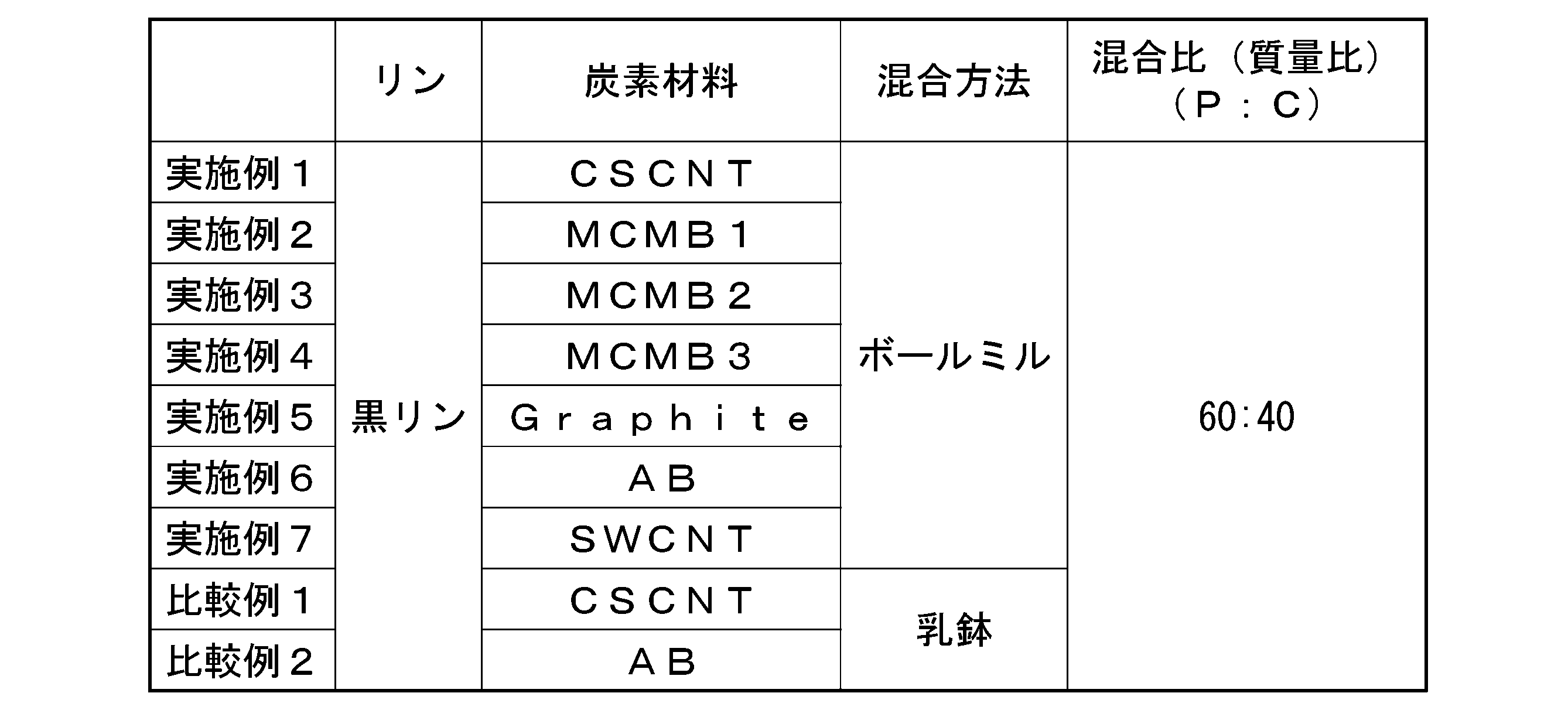
[評価]
得られた材料を用いて、以下の方法で評価用電池を作製し、評価を行った。評価結果を表5に示す。 [evaluation]
Using the obtained material, an evaluation battery was produced and evaluated by the following method. Table 5 shows the evaluation results.
得られた材料を用いて、以下の方法で評価用電池を作製し、評価を行った。評価結果を表5に示す。 [evaluation]
Using the obtained material, an evaluation battery was produced and evaluated by the following method. Table 5 shows the evaluation results.
(評価用電池の作製)
(1)負極の作製
P-C材料又はP-C混合物、導電材、バインダーを秤量し、[P-C材料又はP-C混合物]:[導電材]:[バインダー]=80:10:10(質量比)の混合物とした。用いた材料は以下の通りである。
バインダー:フッ化ビニリデンPVdF クレハKFポリマー#1100(クレハ社製)
導電材 :アセチレンブラック、デンカブラックHS100(デンカ社製) (Preparation of battery for evaluation)
(1) Preparation of negative electrode PC material or PC mixture, conductive material, binder are weighed, [PC material or PC mixture]: [conductive material]: [binder] = 80: 10: 10 (mass ratio). The materials used are as follows.
Binder: Vinylidene fluoride PVdF Kureha KF polymer #1100 (manufactured by Kureha Corporation)
Conductive material: Acetylene black, Denka black HS100 (manufactured by Denka)
メノウ乳鉢を用いて上記混合物と溶媒(NMP(N-メチル-2-ピロリドン))とを混練し、負極スラリーを作製した。このとき、スラリー濃度を調整し、負極スラリー中の負極活物質(P-C材料又はP-C混合物と導電材とバインダーの合計)の含有率を30~60質量%とした。
An agate mortar was used to knead the above mixture and a solvent (NMP (N-methyl-2-pyrrolidone)) to prepare a negative electrode slurry. At this time, the slurry concentration was adjusted so that the content of the negative electrode active material (the total of the PC material or PC mixture, the conductive material and the binder) in the negative electrode slurry was 30 to 60% by mass.
ドクターブレードを用いて負極スラリーを銅箔集電体に塗布し、その後、120℃で1時間送風乾燥させて溶媒を除去して積層体を得た。得られた積層体を10mPaで10秒間加圧プレスした後に、さらに120℃で12時間真空乾燥して、負極を得た。
The negative electrode slurry was applied to a copper foil current collector using a doctor blade, and then air dried at 120°C for 1 hour to remove the solvent and obtain a laminate. The laminate thus obtained was pressed at 10 mPa for 10 seconds, and then vacuum-dried at 120° C. for 12 hours to obtain a negative electrode.
なお、上述の負極スラリーの作製、及び負極の作製は、アルゴン雰囲気のグローブボックス内で実施した。
Note that the preparation of the negative electrode slurry and the preparation of the negative electrode described above were performed in a glove box in an argon atmosphere.
(2)リチウムイオン二次電池の作製
(1)で作製した負極、対極、電解液、セパレータを組み合わせてリチウムイオン二次電池(コイン型電池R2032)を作製した。電池の組み立てはアルゴン雰囲気のグローブボックス内で行った。 (2) Production of Lithium Ion Secondary Battery A lithium ion secondary battery (coin battery R2032) was produced by combining the negative electrode, counter electrode, electrolytic solution and separator produced in (1). The battery was assembled in an argon atmosphere glove box.
(1)で作製した負極、対極、電解液、セパレータを組み合わせてリチウムイオン二次電池(コイン型電池R2032)を作製した。電池の組み立てはアルゴン雰囲気のグローブボックス内で行った。 (2) Production of Lithium Ion Secondary Battery A lithium ion secondary battery (coin battery R2032) was produced by combining the negative electrode, counter electrode, electrolytic solution and separator produced in (1). The battery was assembled in an argon atmosphere glove box.
対極として、金属リチウム箔を使用した。
A metallic lithium foil was used as the counter electrode.
電解液として、LiPF6溶液(キシダ化学社製)に、フルオロエチレンカーボネート(FEC)を10質量%添加した混合液を使用した。
As an electrolytic solution, a mixed solution obtained by adding 10% by mass of fluoroethylene carbonate (FEC) to a LiPF 6 solution (manufactured by Kishida Chemical Co., Ltd.) was used.
LiPF6溶液としては、エチレンカーボネート(EC)とジエチルカーボネート(DEC)とエチルメチルカーボネート(EMC)をそれぞれ体積比で30:35:35とした混合溶媒に、LiPF6を1mol/Lとなるように溶解した溶液を使用した。
As the LiPF 6 solution, LiPF 6 was added to a mixed solvent of ethylene carbonate (EC), diethyl carbonate (DEC), and ethyl methyl carbonate (EMC) at a volume ratio of 30:35:35, respectively, so that the concentration of LiPF 6 was 1 mol/L. A dissolved solution was used.
セパレータとして、ポリエチレン製多孔質フィルムの上に耐熱多孔層を積層した積層フィルムセパレータ(16μm厚)を使用した。
As the separator, a laminated film separator (16 μm thick) was used in which a heat-resistant porous layer was laminated on a polyethylene porous film.
(評価1.放電容量)
上記評価用電池を用いて、25℃保持下、以下に示す条件で充放電試験を実施した。ここで、リンの理論容量を2600mAh/gとして、電極容量を1時間で充電又は放電する1C電流を2600mA/gとした。充放電試験においては、負極に含まれるリンの質量から、1C電流を計算した。実施例における1Cの定義については、以下同様とする。
充電最小電圧:0.005V
充電電流 :0.1C (1C=2600mA/g)
放電最大電圧:2.0V
放電電流 :0.1C (1C=2600mA/g) (Evaluation 1. Discharge capacity)
Using the evaluation battery described above, a charge/discharge test was performed under the following conditions while maintaining at 25°C. Here, the theoretical capacity of phosphorus is 2600 mAh/g, and the 1C current for charging or discharging the electrode capacity in 1 hour is 2600 mA/g. In the charge/discharge test, the 1C current was calculated from the mass of phosphorus contained in the negative electrode. The definition of 1C in the examples is the same below.
Charging minimum voltage: 0.005V
Charging current: 0.1C (1C = 2600mA/g)
Maximum discharge voltage: 2.0V
Discharge current: 0.1C (1C = 2600mA/g)
上記評価用電池を用いて、25℃保持下、以下に示す条件で充放電試験を実施した。ここで、リンの理論容量を2600mAh/gとして、電極容量を1時間で充電又は放電する1C電流を2600mA/gとした。充放電試験においては、負極に含まれるリンの質量から、1C電流を計算した。実施例における1Cの定義については、以下同様とする。
充電最小電圧:0.005V
充電電流 :0.1C (1C=2600mA/g)
放電最大電圧:2.0V
放電電流 :0.1C (1C=2600mA/g) (
Using the evaluation battery described above, a charge/discharge test was performed under the following conditions while maintaining at 25°C. Here, the theoretical capacity of phosphorus is 2600 mAh/g, and the 1C current for charging or discharging the electrode capacity in 1 hour is 2600 mA/g. In the charge/discharge test, the 1C current was calculated from the mass of phosphorus contained in the negative electrode. The definition of 1C in the examples is the same below.
Charging minimum voltage: 0.005V
Charging current: 0.1C (1C = 2600mA/g)
Maximum discharge voltage: 2.0V
Discharge current: 0.1C (1C = 2600mA/g)
評価1においては、放電容量が500mAh/g以上であるものを良品、放電容量が500mAh/g未満であるものを不良と判断した。参考値として、炭素材料である黒鉛の理論放電容量は、372mAh/gである。
In Evaluation 1, a battery with a discharge capacity of 500 mAh/g or more was judged to be good, and a battery with a discharge capacity of less than 500 mAh/g was judged to be defective. As a reference value, the theoretical discharge capacity of graphite, which is a carbon material, is 372 mAh/g.
(評価2.サイクル特性)
上記評価用電池を用いて、25℃保持下、以下に示す条件で充放電を繰り返してサイクル特性を評価した。1Cレート電流における100サイクル目の放電容量D100と、1サイクル目の充電容量D1との比(D100/D1)を用いて、サイクル特性を評価した。D100/D1が大きいほど、サイクルに伴う放電容量の維持率が高いことを示すことから、負極活物質として優れると判断することができる。
充電最小電圧:0.005V
充電電流 :1C (1C=2600mA/g)
放電最大電圧:2.0V
放電電流 :1C (1C=2600mA/g) (Evaluation 2. Cycle characteristics)
Using the battery for evaluation described above, the cycle characteristics were evaluated by repeating charging and discharging under the conditions shown below while maintaining the temperature at 25°C. Cycle characteristics were evaluated using the ratio (D100/D1) of the discharge capacity D100 at the 100th cycle and the charge capacity D1 at the 1st cycle at a 1C rate current. A larger D100/D1 indicates a higher discharge capacity maintenance rate with cycles, and thus can be judged to be excellent as a negative electrode active material.
Charging minimum voltage: 0.005V
Charging current: 1C (1C = 2600mA/g)
Maximum discharge voltage: 2.0V
Discharge current: 1C (1C = 2600mA/g)
上記評価用電池を用いて、25℃保持下、以下に示す条件で充放電を繰り返してサイクル特性を評価した。1Cレート電流における100サイクル目の放電容量D100と、1サイクル目の充電容量D1との比(D100/D1)を用いて、サイクル特性を評価した。D100/D1が大きいほど、サイクルに伴う放電容量の維持率が高いことを示すことから、負極活物質として優れると判断することができる。
充電最小電圧:0.005V
充電電流 :1C (1C=2600mA/g)
放電最大電圧:2.0V
放電電流 :1C (1C=2600mA/g) (
Using the battery for evaluation described above, the cycle characteristics were evaluated by repeating charging and discharging under the conditions shown below while maintaining the temperature at 25°C. Cycle characteristics were evaluated using the ratio (D100/D1) of the discharge capacity D100 at the 100th cycle and the charge capacity D1 at the 1st cycle at a 1C rate current. A larger D100/D1 indicates a higher discharge capacity maintenance rate with cycles, and thus can be judged to be excellent as a negative electrode active material.
Charging minimum voltage: 0.005V
Charging current: 1C (1C = 2600mA/g)
Maximum discharge voltage: 2.0V
Discharge current: 1C (1C = 2600mA/g)
評価2においては、D100/D1が50%以上であるものを良品、D100/D1が50%未満であるものを不良と判断した。
In evaluation 2, those with D100/D1 of 50% or more were judged to be non-defective, and those with D100/D1 of less than 50% were judged to be defective.
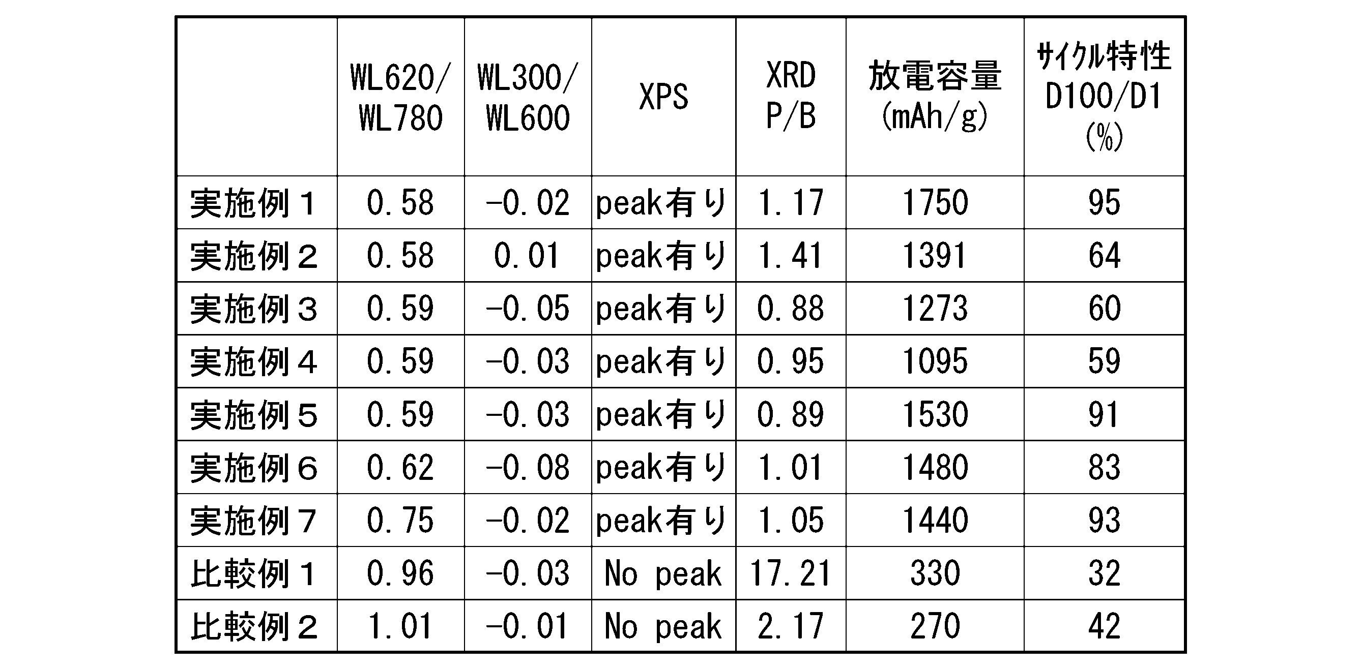
図7は、実施例1、4~7で作製したP-C材料、及び比較例2で作製したP-C混合物の熱重量測定の結果を示すグラフである。図7に示すように、P-C材料はいずれもWL620/WL780が0.1以上0.9以下を満たしていた。
7 is a graph showing the results of thermogravimetric measurements of the PC materials prepared in Examples 1 and 4-7 and the PC mixture prepared in Comparative Example 2. FIG. As shown in FIG. 7, all of the PC materials satisfied WL 620 /WL 780 of 0.1 or more and 0.9 or less.
また、実施例7のP-C材料は、WL620/WL780が0.75であり、他の実施例のP-C材料と比べ大きかった。実施例7で用いた炭素材料であるSWCNTは、他の炭素材料と比べ、炭素原子量に対するエッジサイトの量が少ないと考えられる。このようにエッジサイトが少ない炭素材料では、エッジサイトが多い炭素材料と比べ生じるP-C結合の量が少ないと考えられる。このようなP-C結合の量の差が、実施例7のP-C材料と、他の実施例のP-C材料との熱重量測定の結果の差に表れたと考えられる。
In addition, the PC material of Example 7 had WL 620 /WL 780 of 0.75, which was larger than the PC materials of other examples. SWCNT, which is the carbon material used in Example 7, is considered to have a smaller amount of edge sites relative to the amount of carbon atoms than other carbon materials. It is considered that the amount of PC bonds generated in a carbon material with a small number of edge sites is smaller than that in a carbon material with a large number of edge sites. It is believed that such a difference in the amount of PC bonds appeared in the difference in the results of thermogravimetry between the PC material of Example 7 and the PC materials of other Examples.
対して、比較例1,2のP-C混合物は、WL620/WL780が0.9よりも大きく、測定温度350℃から450℃あたりで急峻な重量減少を示し、500℃以上の温度ではほとんど重量減少は見られなかった。そのため、比較例1~2のP-C混合物は、620℃以上の高温に耐えうる新たな結合が形成されておらず、原料であるリンと炭素材料との混合物の状態であると言える。なお、WL300/WL600については、いずれの測定試料も-0.1以上0.1以下を満たしていた。
On the other hand, the PC mixtures of Comparative Examples 1 and 2 have a WL 620 /WL 780 greater than 0.9, exhibit a sharp weight loss at a measurement temperature of 350°C to 450°C, and a temperature of 500°C or higher. Almost no weight loss was observed. Therefore, it can be said that the PC mixtures of Comparative Examples 1 and 2 are in a state of a mixture of the raw material phosphorus and the carbon material without forming new bonds that can withstand a high temperature of 620° C. or higher. Regarding WL 300 /WL 600 , all measurement samples satisfied −0.1 or more and 0.1 or less.
図8は、実施例1~5、7で作製したP-C材料のXPSスペクトルである。図8に示すように、いずれのP-C材料においても132~136eVの範囲にピークを生じ、P-C結合が形成されていることが確認できる。なお、実施例6のP-C材料においても132~136eVの範囲でピークを確認している。
FIG. 8 is the XPS spectra of the PC materials produced in Examples 1-5 and 7. As shown in FIG. 8, any PC material has a peak in the range of 132 to 136 eV, confirming the formation of a PC bond. A peak in the range of 132 to 136 eV was confirmed for the PC material of Example 6 as well.
一方、図8には図示していないが、比較例1,2のP-C混合物は、XPSスペクトルで132~136eVの範囲にピークは無く、P-C結合を確認できなかった。
On the other hand, although not shown in FIG. 8, the PC mixtures of Comparative Examples 1 and 2 did not have a peak in the range of 132 to 136 eV in the XPS spectrum, and the PC bond could not be confirmed.
図9は、実施例1~7で作製したP-C材料、及び比較例1,2で作製したP-C混合物のXRDプロファイルである。図9に示すように、いずれのP-C材料においても、2θ=26.3°の位置にピークが確認できず、炭素材料がアモルファス、又は結晶状態が確認できないほど微細な炭素材料となっていると判断することができる。
FIG. 9 is the XRD profile of the PC materials produced in Examples 1 to 7 and the PC mixtures produced in Comparative Examples 1 and 2. As shown in FIG. 9, no peak was observed at 2θ=26.3° in any of the PC materials, and the carbon material was amorphous, or the carbon material was so fine that the crystalline state could not be confirmed. can be determined to be
一方、比較例1,2のP-C混合物では、2θ=26.3°の位置にピークが確認できたことから、炭素材料のアモルファス化が不十分であったと判断できる。
On the other hand, in the PC mixtures of Comparative Examples 1 and 2, a peak was confirmed at the position of 2θ = 26.3°, so it can be judged that the amorphization of the carbon material was insufficient.
図10は、実施例1~7および比較例2のP-C材料を用いたリチウム二次電池の100サイクルまでの放電容量を示すグラフである。電池性能を評価したところ、実施例1~7のP-C材料は、負極活物質として用いた場合に、放電容量が高く、且つサイクル特性に優れることが分かった。対して、比較例2のP-C混合物では、十分な放電容量を得ることが出来ず、且つサイクル特性は実施例に比較して極めて低かった。
FIG. 10 is a graph showing the discharge capacity up to 100 cycles of lithium secondary batteries using the PC materials of Examples 1 to 7 and Comparative Example 2. Evaluation of battery performance revealed that the PC materials of Examples 1 to 7 had high discharge capacity and excellent cycle characteristics when used as negative electrode active materials. On the other hand, in the PC mixture of Comparative Example 2, a sufficient discharge capacity could not be obtained, and the cycle characteristics were extremely low compared to those of Examples.
以上の結果から、本発明が有用であることが確かめられた。
From the above results, it was confirmed that the present invention is useful.
3,120…負極、10…リチウム二次電池、50…粒子、51…コア粒子、52…炭素皮膜、1000…全固体リチウム二次電池(リチウム二次電池)
3, 120... Negative electrode, 10... Lithium secondary battery, 50... Particles, 51... Core particles, 52... Carbon film, 1000... All solid lithium secondary battery (lithium secondary battery)
Claims (12)
- リン原子と、炭素原子とを含むリン-炭素複合材料であって、
前記リン-炭素複合材料におけるリン原子の含有率が、10質量%以上95質量%以下であり、
前記リン-炭素複合材料における炭素原子の含有率が、5質量%以上90質量%以下であり、
下記条件の熱重量測定で求められる測定温度620℃における重量減少率WL620と、測定温度780℃における重量減少率WL780との比WL620/WL780が、0.1以上0.9以下であるリン-炭素複合材料。
(熱重量測定)
10mgのリン-炭素複合材料を精秤して試料とし、熱重量測定装置を用い、窒素気流下で50℃から780℃まで10℃/分の昇温速度で加熱したときの重量変化を測定する。
(重量減少率)
精秤した試料の重量に対する、測定温度における試料の重量の割合を、測定温度における重量減少率(重量%)とする。 A phosphorus-carbon composite material comprising phosphorus atoms and carbon atoms,
The content of phosphorus atoms in the phosphorus-carbon composite material is 10% by mass or more and 95% by mass or less,
The phosphorus-carbon composite material has a carbon atom content of 5% by mass or more and 90% by mass or less,
The ratio WL 620 /WL 780 between the weight loss rate WL 620 at a measurement temperature of 620 ° C. and the weight loss rate WL 780 at a measurement temperature of 780 ° C. obtained by thermogravimetry under the following conditions is 0.1 or more and 0.9 or less. Certain phosphorous-carbon composites.
(thermogravimetry)
10 mg of phosphorus-carbon composite material is precisely weighed as a sample, and a thermogravimetric measurement device is used to measure the weight change when heated from 50 ° C. to 780 ° C. at a temperature increase rate of 10 ° C./min under a nitrogen stream. .
(Weight reduction rate)
The ratio of the weight of the sample at the measurement temperature to the weight of the precisely weighed sample is defined as the weight reduction rate (% by weight) at the measurement temperature. - 上記熱重量測定で求められる測定温度300℃における重量減少率WL300と、測定温度600℃における重量減少率WL600との比WL300/WL600が、-0.1以上0.1以下である請求項1に記載のリン-炭素複合材料。 The ratio WL 300 /WL 600 between the weight loss rate WL 300 at the measurement temperature of 300 ° C. and the weight loss rate WL 600 at the measurement temperature of 600 ° C. determined by the thermogravimetry is -0.1 or more and 0.1 or less. The phosphorus-carbon composite material according to claim 1.
- XPSスペクトルにおいて、リン原子と炭素原子との結合を示すピークを有する請求項1又は2に記載のリン-炭素複合材料。 The phosphorus-carbon composite material according to claim 1 or 2, which has a peak indicating a bond between a phosphorus atom and a carbon atom in the XPS spectrum.
- CuKα線を用いて測定したXRDプロファイルにおいて、2θ=20°の強度I20、2θ=26.3°の強度I26.3、及び2θ=40°の強度I40が、以下の式(1)~(3)を満たす請求項1から3のいずれか1項に記載のリン-炭素複合材料。
|P|/|B|<2 …(1)
P=I26.3-I40 …(2)
B=(I20-I40)×(26.3-40)/(20-40) …(3) In the XRD profile measured using CuKα rays, the intensity I 20 at 2θ = 20°, the intensity I 26.3 at 2θ = 26.3°, and the intensity I 40 at 2θ = 40 ° are expressed by the following formula (1) The phosphorus-carbon composite material according to any one of claims 1 to 3, which satisfies (3).
|P|/|B|<2 (1)
P= I26.3 - I40 (2)
B=( I20 - I40 )×(26.3-40)/(20-40) (3) - リン原子を含むコア粒子と、
前記コア粒子の表面を覆う炭素皮膜と、を有する請求項1から4のいずれか1項に記載のリン-炭素複合材料。 a core particle containing phosphorus atoms;
5. The phosphorus-carbon composite material according to any one of claims 1 to 4, further comprising a carbon film covering the surface of the core particles. - 炭素材料と、リンとを圧縮を伴う混合粉砕処理により複合化する工程を有するリン-炭素複合材料の製造方法。 A method for producing a phosphorus-carbon composite material, which includes a step of compounding a carbon material and phosphorus by mixing and pulverizing with compression.
- 炭素材料と、リンとをボールミル混合する工程を有するリン-炭素複合材料の製造方法。 A method for producing a phosphorus-carbon composite material, which includes a step of mixing a carbon material and phosphorus in a ball mill.
- 前記炭素材料が、アモルファスカーボン、黒鉛、多孔性カーボン、メソカーボンマイクロビーズ、フラーレン、カーボンナノチューブ、グラフェン、グラフェンオキサイド、カーボンナイトライト(C3N4)及び積層カーボンナノファイバーからなる群から選ばれる少なくとも1種である請求項6又は7に記載のリン-炭素複合材料の製造方法。 The carbon material is at least selected from the group consisting of amorphous carbon, graphite, porous carbon, mesocarbon microbeads, fullerenes, carbon nanotubes, graphene, graphene oxide, carbon nitrite ( C3N4 ) and laminated carbon nanofibers . The method for producing a phosphorus-carbon composite material according to claim 6 or 7, wherein the phosphorus-carbon composite material is one.
- 前記リンが黒リンである請求項6から8のいずれか1項に記載のリン-炭素複合材料の製造方法。 The method for producing a phosphorus-carbon composite material according to any one of claims 6 to 8, wherein the phosphorus is black phosphorus.
- 請求項1から5のいずれか1項に記載のリン-炭素複合材料を含む負極活物質。 A negative electrode active material comprising the phosphorus-carbon composite material according to any one of claims 1 to 5.
- 請求項10に記載の負極活物質を含むリチウム二次電池用負極。 A negative electrode for a lithium secondary battery, comprising the negative electrode active material according to claim 10.
- 請求項11に記載のリチウム二次電池用負極を含むリチウム二次電池。 A lithium secondary battery comprising the negative electrode for a lithium secondary battery according to claim 11.
Applications Claiming Priority (2)
| Application Number | Priority Date | Filing Date | Title |
|---|---|---|---|
| JP2021-211116 | 2021-12-24 | ||
| JP2021211116A JP2023095306A (en) | 2021-12-24 | 2021-12-24 | Phosphorus-carbon composite material, manufacturing method of phosphorus-carbon composite material, negative electrode active material, negative electrode for lithium secondary battery and lithium secondary battery |
Publications (1)
| Publication Number | Publication Date |
|---|---|
| WO2023120724A1 true WO2023120724A1 (en) | 2023-06-29 |
Family
ID=86902877
Family Applications (1)
| Application Number | Title | Priority Date | Filing Date |
|---|---|---|---|
| PCT/JP2022/047738 WO2023120724A1 (en) | 2021-12-24 | 2022-12-23 | Phosphorus-carbon composite material, phosphorus-carbon composite material production method, negative electrode active material, negative electrode for lithium secondary battery, and lithium secondary battery |
Country Status (2)
| Country | Link |
|---|---|
| JP (1) | JP2023095306A (en) |
| WO (1) | WO2023120724A1 (en) |
Citations (1)
| Publication number | Priority date | Publication date | Assignee | Title |
|---|---|---|---|---|
| CN112018363A (en) * | 2020-08-31 | 2020-12-01 | 中国科学技术大学 | Black phosphorus-based composite negative electrode material, preparation method thereof and application thereof in metal secondary battery |
-
2021
- 2021-12-24 JP JP2021211116A patent/JP2023095306A/en active Pending
-
2022
- 2022-12-23 WO PCT/JP2022/047738 patent/WO2023120724A1/en unknown
Patent Citations (1)
| Publication number | Priority date | Publication date | Assignee | Title |
|---|---|---|---|---|
| CN112018363A (en) * | 2020-08-31 | 2020-12-01 | 中国科学技术大学 | Black phosphorus-based composite negative electrode material, preparation method thereof and application thereof in metal secondary battery |
Non-Patent Citations (3)
| Title |
|---|
| JIE SUN, ZHENG GUANGYUAN, LEE HYUN-WOOK, LIU NIAN, WANG HAOTIAN, YAO HONGBIN, YANG WENSHENG, CUI YI: "Formation of Stable Phosphorus–Carbon Bond for Enhanced Performance in Black Phosphorus Nanoparticle–Graphite Composite Battery Anodes", NANO LETTERS, AMERICAN CHEMICAL SOCIETY, US, vol. 14, no. 8, 14 July 2014 (2014-07-14), US , pages 4573 - 4580, XP055547016, ISSN: 1530-6984, DOI: 10.1021/nl501617j * |
| SHI YANG, YI ZHIBIN, KUANG YANPING, GUO HANYU, LI YINGZHI, LIU CHEN, LU ZHOUGUANG: "Constructing stable covalent bonding in black phosphorus/reduced graphene oxide for lithium ion battery anodes", CHEMICAL COMMUNICATIONS, ROYAL SOCIETY OF CHEMISTRY, UK, vol. 56, no. 78, 1 October 2020 (2020-10-01), UK , pages 11613 - 11616, XP093073675, ISSN: 1359-7345, DOI: 10.1039/D0CC03698F * |
| YANG J., MO F., HUANG L., LIANG H., SUN G., PENG S.: "Building a C-P bond to unlock the reversible and fast lithium storage performance of black phosphorus in all-solid-state lithium-ion batteries", MATERIALS TODAY ENERGY, vol. 20, 1 June 2021 (2021-06-01), pages 100662, XP093073672, ISSN: 2468-6069, DOI: 10.1016/j.mtener.2021.100662 * |
Also Published As
| Publication number | Publication date |
|---|---|
| JP2023095306A (en) | 2023-07-06 |
Similar Documents
| Publication | Publication Date | Title |
|---|---|---|
| US10586980B2 (en) | Composite cathode active material, method of preparing the composite cathode active material, and cathode and lithium battery each including the composite cathode active material | |
| CN107408686B (en) | Cathode active material for lithium ion secondary battery, method for manufacturing same, and lithium ion secondary battery comprising same | |
| WO2020208872A1 (en) | Lithium metal complex oxide powder and lithium secondary battery positive electrode active material | |
| EP2960971B1 (en) | Composite active material for lithium secondary battery and method for producing same | |
| WO2016203696A1 (en) | Negative electrode active material for nonaqueous electrolyte secondary batteries, nonaqueous electrolyte secondary battery, and method for producing negative electrode material for nonaqueous electrolyte secondary batteries | |
| WO2015182665A1 (en) | Positive electrode active material for lithium secondary batteries, positive electrode for lithium secondary batteries, and lithium secondary battery | |
| US7811478B2 (en) | Positive-electrode active material powder | |
| CN108292748B (en) | Negative electrode active material, lithium ion secondary battery and method for producing same, mixed negative electrode active material, negative electrode | |
| CN108718535B (en) | Negative electrode active material, method for producing negative electrode active material, material containing negative electrode active material, and lithium ion secondary battery | |
| US10276862B2 (en) | Composite cathode active material, method of preparing the composite cathode active material, and cathode and lithium battery each including the composite cathode active material | |
| WO2014129096A1 (en) | Lithium-ion secondary battery and manufacturing method therefor | |
| JP2008135379A (en) | Lithium secondary battery | |
| CN108352522B (en) | Negative electrode active material, lithium ion secondary battery, and method for producing same | |
| US11929494B2 (en) | Anode active material including low-defect turbostratic carbon | |
| CN114744183A (en) | Negative electrode active material and method for producing same, mixed negative electrode active material, negative electrode, lithium ion secondary battery, and method for producing same | |
| JP2023015403A (en) | Non-aqueous electrolyte secondary battery | |
| JP2018097961A (en) | Positive electrode for lithium ion secondary battery and lithium ion secondary battery | |
| WO2016152716A1 (en) | Negative electrode for lithium ion secondary battery and secondary battery | |
| JP7040832B1 (en) | Negative electrode active material for lithium ion secondary battery, its manufacturing method, and negative electrode for lithium ion secondary battery | |
| WO2018021480A1 (en) | Positive electrode active substance for lithium ion secondary batteries, positive electrode for lithium ion secondary batteries, and lithium ion secondary battery using same | |
| WO2023120724A1 (en) | Phosphorus-carbon composite material, phosphorus-carbon composite material production method, negative electrode active material, negative electrode for lithium secondary battery, and lithium secondary battery | |
| JP7235650B2 (en) | Lithium transition metal composite oxide powder, nickel-containing transition metal composite hydroxide powder, positive electrode active material for lithium secondary battery, positive electrode for lithium secondary battery and lithium secondary battery | |
| JP5332121B2 (en) | Positive electrode active material powder | |
| JP6980053B2 (en) | A method for producing a positive electrode active material precursor for a lithium secondary battery, a method for producing a positive electrode active material precursor for a lithium secondary battery, and a method for producing a positive electrode active material for a lithium secondary battery. | |
| WO2019053861A1 (en) | Electrode and nonaqueous electrolyte battery |
Legal Events
| Date | Code | Title | Description |
|---|---|---|---|
| 121 | Ep: the epo has been informed by wipo that ep was designated in this application |
Ref document number: 22911425 Country of ref document: EP Kind code of ref document: A1 |