EP4455035A1 - Dispositif du type à carrousel pour remplir un liquide dans une pluralité de récipients - Google Patents
Dispositif du type à carrousel pour remplir un liquide dans une pluralité de récipients Download PDFInfo
- Publication number
- EP4455035A1 EP4455035A1 EP24171850.1A EP24171850A EP4455035A1 EP 4455035 A1 EP4455035 A1 EP 4455035A1 EP 24171850 A EP24171850 A EP 24171850A EP 4455035 A1 EP4455035 A1 EP 4455035A1
- Authority
- EP
- European Patent Office
- Prior art keywords
- unit
- container
- filling
- drive unit
- flange
- Prior art date
- Legal status (The legal status is an assumption and is not a legal conclusion. Google has not performed a legal analysis and makes no representation as to the accuracy of the status listed.)
- Pending
Links
Images


Classifications
-
- B—PERFORMING OPERATIONS; TRANSPORTING
- B67—OPENING, CLOSING OR CLEANING BOTTLES, JARS OR SIMILAR CONTAINERS; LIQUID HANDLING
- B67C—CLEANING, FILLING WITH LIQUIDS OR SEMILIQUIDS, OR EMPTYING, OF BOTTLES, JARS, CANS, CASKS, BARRELS, OR SIMILAR CONTAINERS, NOT OTHERWISE PROVIDED FOR; FUNNELS
- B67C3/00—Bottling liquids or semiliquids; Filling jars or cans with liquids or semiliquids using bottling or like apparatus; Filling casks or barrels with liquids or semiliquids
- B67C3/02—Bottling liquids or semiliquids; Filling jars or cans with liquids or semiliquids using bottling or like apparatus
- B67C3/22—Details
- B67C3/225—Means for filling simultaneously, e.g. in a rotary filling apparatus or multiple rows of containers
-
- B—PERFORMING OPERATIONS; TRANSPORTING
- B65—CONVEYING; PACKING; STORING; HANDLING THIN OR FILAMENTARY MATERIAL
- B65B—MACHINES, APPARATUS OR DEVICES FOR, OR METHODS OF, PACKAGING ARTICLES OR MATERIALS; UNPACKING
- B65B43/00—Forming, feeding, opening or setting-up containers or receptacles in association with packaging
- B65B43/42—Feeding or positioning bags, boxes, or cartons in the distended, opened, or set-up state; Feeding preformed rigid containers, e.g. tins, capsules, glass tubes, glasses, to the packaging position; Locating containers or receptacles at the filling position; Supporting containers or receptacles during the filling operation
- B65B43/50—Feeding or positioning bags, boxes, or cartons in the distended, opened, or set-up state; Feeding preformed rigid containers, e.g. tins, capsules, glass tubes, glasses, to the packaging position; Locating containers or receptacles at the filling position; Supporting containers or receptacles during the filling operation using rotary tables or turrets
-
- B—PERFORMING OPERATIONS; TRANSPORTING
- B65—CONVEYING; PACKING; STORING; HANDLING THIN OR FILAMENTARY MATERIAL
- B65B—MACHINES, APPARATUS OR DEVICES FOR, OR METHODS OF, PACKAGING ARTICLES OR MATERIALS; UNPACKING
- B65B25/00—Packaging other articles presenting special problems
- B65B25/001—Packaging other articles presenting special problems of foodstuffs, combined with their conservation
-
- B—PERFORMING OPERATIONS; TRANSPORTING
- B65—CONVEYING; PACKING; STORING; HANDLING THIN OR FILAMENTARY MATERIAL
- B65B—MACHINES, APPARATUS OR DEVICES FOR, OR METHODS OF, PACKAGING ARTICLES OR MATERIALS; UNPACKING
- B65B65/00—Details peculiar to packaging machines and not otherwise provided for; Arrangements of such details
- B65B65/02—Driving gear
-
- B—PERFORMING OPERATIONS; TRANSPORTING
- B67—OPENING, CLOSING OR CLEANING BOTTLES, JARS OR SIMILAR CONTAINERS; LIQUID HANDLING
- B67C—CLEANING, FILLING WITH LIQUIDS OR SEMILIQUIDS, OR EMPTYING, OF BOTTLES, JARS, CANS, CASKS, BARRELS, OR SIMILAR CONTAINERS, NOT OTHERWISE PROVIDED FOR; FUNNELS
- B67C7/00—Concurrent cleaning, filling, and closing of bottles; Processes or devices for at least two of these operations
-
- B—PERFORMING OPERATIONS; TRANSPORTING
- B65—CONVEYING; PACKING; STORING; HANDLING THIN OR FILAMENTARY MATERIAL
- B65B—MACHINES, APPARATUS OR DEVICES FOR, OR METHODS OF, PACKAGING ARTICLES OR MATERIALS; UNPACKING
- B65B25/00—Packaging other articles presenting special problems
-
- B—PERFORMING OPERATIONS; TRANSPORTING
- B65—CONVEYING; PACKING; STORING; HANDLING THIN OR FILAMENTARY MATERIAL
- B65B—MACHINES, APPARATUS OR DEVICES FOR, OR METHODS OF, PACKAGING ARTICLES OR MATERIALS; UNPACKING
- B65B3/00—Packaging plastic material, semiliquids, liquids or mixed solids and liquids, in individual containers or receptacles, e.g. bags, sacks, boxes, cartons, cans, or jars
-
- B—PERFORMING OPERATIONS; TRANSPORTING
- B65—CONVEYING; PACKING; STORING; HANDLING THIN OR FILAMENTARY MATERIAL
- B65B—MACHINES, APPARATUS OR DEVICES FOR, OR METHODS OF, PACKAGING ARTICLES OR MATERIALS; UNPACKING
- B65B43/00—Forming, feeding, opening or setting-up containers or receptacles in association with packaging
- B65B43/42—Feeding or positioning bags, boxes, or cartons in the distended, opened, or set-up state; Feeding preformed rigid containers, e.g. tins, capsules, glass tubes, glasses, to the packaging position; Locating containers or receptacles at the filling position; Supporting containers or receptacles during the filling operation
- B65B43/44—Feeding or positioning bags, boxes, or cartons in the distended, opened, or set-up state; Feeding preformed rigid containers, e.g. tins, capsules, glass tubes, glasses, to the packaging position; Locating containers or receptacles at the filling position; Supporting containers or receptacles during the filling operation from supply magazines
-
- B—PERFORMING OPERATIONS; TRANSPORTING
- B65—CONVEYING; PACKING; STORING; HANDLING THIN OR FILAMENTARY MATERIAL
- B65B—MACHINES, APPARATUS OR DEVICES FOR, OR METHODS OF, PACKAGING ARTICLES OR MATERIALS; UNPACKING
- B65B51/00—Devices for, or methods of, sealing or securing package folds or closures; Devices for gathering or twisting wrappers, or necks of bags
-
- B—PERFORMING OPERATIONS; TRANSPORTING
- B65—CONVEYING; PACKING; STORING; HANDLING THIN OR FILAMENTARY MATERIAL
- B65B—MACHINES, APPARATUS OR DEVICES FOR, OR METHODS OF, PACKAGING ARTICLES OR MATERIALS; UNPACKING
- B65B57/00—Automatic control, checking, warning, or safety devices
-
- B—PERFORMING OPERATIONS; TRANSPORTING
- B65—CONVEYING; PACKING; STORING; HANDLING THIN OR FILAMENTARY MATERIAL
- B65B—MACHINES, APPARATUS OR DEVICES FOR, OR METHODS OF, PACKAGING ARTICLES OR MATERIALS; UNPACKING
- B65B61/00—Auxiliary devices, not otherwise provided for, for operating on sheets, blanks, webs, binding material, containers or packages
- B65B61/26—Auxiliary devices, not otherwise provided for, for operating on sheets, blanks, webs, binding material, containers or packages for marking or coding completed packages
-
- B—PERFORMING OPERATIONS; TRANSPORTING
- B65—CONVEYING; PACKING; STORING; HANDLING THIN OR FILAMENTARY MATERIAL
- B65B—MACHINES, APPARATUS OR DEVICES FOR, OR METHODS OF, PACKAGING ARTICLES OR MATERIALS; UNPACKING
- B65B7/00—Closing containers or receptacles after filling
Definitions
- the present invention relates to a rotary type device for filling a filling medium, in particular a foodstuff, into a plurality of containers.
- filling systems are known from the state of the art, with which a wide variety of filling media or filling goods can be filled into a wide variety of packaging.
- hot and cold, liquid, pasty and powdery filling goods such as soups, drinks, dairy products and spreads, but also piece goods, such as pasta, can be filled into packaging of different sizes, which can be made of different materials.
- piece goods such as pasta
- Such filling systems must be able to dose precisely, comply with high hygiene standards and guarantee a high level of consumer safety.
- linear machines In the case of fully automatic filling systems, in which not only the filling process but also the closing and transporting of the packaging takes place automatically, a basic distinction is made between linear and rotary machines. In linear machines, all process steps take place along a straight conveyor track, while in rotary machines the conveyor track is a Circular track or oval track. The packaging is usually transported standing or hanging, depending on the contents and the type and size of the packaging.
- the general structure of the filling systems known from the state of the art comprises a basic structure with a table top, beneath which all drive components are housed.
- the handling of the packaging to be filled and the individual process steps, which are carried out by so-called functional units, take place above the table top.
- individual packages such as cups
- the cups are first stacked from a stacking unit and placed in respective openings provided in a turntable that serves as a transport unit.
- the cups can be sterilized and filled with filling material in a filling and dosing unit.
- the filled cups are then provided with a seal and sealed.
- the filled cups can also be closed with a lid.
- the cups can be printed and tested for leaks.
- the filled and sealed cups are lifted out of the container openings by means of a lifting unit, usually pneumatically driven, which moves through the table top. They then leave the filling system in an outlet unit and are packaged elsewhere and placed on pallets.
- the table top serves as protection for the drive side, which must not be cleaned using wet chemicals. At the same time, the table top makes it more difficult to clean the floor beneath the drive side.
- the individual functional units are stored on the table top. Because any lifting units move through the table top and the process step of lifting the cups out of the cup openings is therefore fixed locally on the table top, the position and often also the number of functional units is largely fixed. In the event that an existing filling system is to be converted to a different filling material, for example where germ-free filling is necessary, the filling system would have to be converted to a considerable extent and equipped with a different table top, because the lifting unit may not be able to remain in the same place.
- One object of the present invention is therefore to minimize or even eliminate any disadvantages known from the prior art.
- one object of the present invention is to propose a structure for a rotary machine that is easier to clean and has a modular structure so that any functional units can be used very variably in terms of location.
- the invention relates to a rotary type device for filling a filling medium, in particular a foodstuff, into a plurality of containers.
- the device comprises a drive unit and a plurality of container receptacles, each of which is designed to receive a container and can be rotated about a vertical axis by the drive unit.
- the device according to the invention is characterized in that the device further comprises at least one functional unit which is selected from the group consisting of a container stacking unit, a container filling unit, a container covering unit, a container sealing unit, a container printing unit, a container inspection unit and a container discharge unit, and that the at least one functional unit is mechanically coupled to the drive unit.
- the at least one functional unit is clamped to the drive unit.
- the at least one functional unit is clamped to a stationary flange provided on the drive unit.
- the at least one functional unit is preferably mechanically coupled on the one hand to the drive unit and on the other hand to a support ring.
- the support ring is arranged in the radial direction outside the plurality of container receptacles.
- the support ring is designed as a closed, circular ring.
- the support ring is supported on the ground by means of a plurality of vertical floor supports mounted on the ground.
- the plurality of floor supports are mechanically coupled to the drive unit by means of a plurality of horizontal cross supports.
- the drive unit has a stationary hollow shaft and a motor-driven rotor radially outside the stationary hollow shaft, and if the drive unit has a plurality of flanges spaced apart in the vertical direction and projecting outwards in the radial direction, of which at least one flange is rotatable with the rotor and at least one flange is stationary.
- the container receptacles are openings designed to receive a cup and/or a bucket and/or a bottle.
- the device is designed for filling a liquid or pasty food into a plurality of containers.
- the device according to the invention for filling a filling medium into a large number of containers is suitable for filling a wide variety of filling goods, for example hot, cold, liquid, pasty or powdery filling goods, such as soups, drinks, dairy products and spreads, but also piece goods, such as pasta, into different packaging made of different materials, for example plastic, glass, cardboard, etc.
- the filling device according to the invention which is also conventionally referred to as a filling system, is suitable for filling liquid or pasty foodstuffs into a large number of containers, such as cups, buckets or bottles.
- the present invention is limited exclusively to rotary-type filling systems.
- the packages pass through the individual process steps along a circular or oval conveyor track, which usually encloses an angle of 270° to 360°.
- a filling device 1 according to a preferred embodiment of the invention shown is not complete in that, for example, functional units 50 (see Fig. 4 ), such as a container stacking unit, a container filling unit, a container capping unit, a container sealing unit, a container printing unit, a container inspection unit and a container discharge unit, in Fig. 1 are not shown.
- functional units 50 such as a container stacking unit, a container filling unit, a container capping unit, a container sealing unit, a container printing unit, a container inspection unit and a container discharge unit, in Fig. 1 are not shown.
- any electrical and pneumatic lines and control modules necessary for the proper operation of a filling plant shown in Fig. 1 shown.
- the in Fig. 1 The structure shown essentially comprises a drive unit 10 arranged centrally or centrally relative to the circular transport path, a plurality of transport units 20, a plurality of lifting units 30 and a support ring 40.
- Fig. 1 Different transport units 20 can be seen.
- the transport units 20 are mechanically coupled or fastened to the drive unit 10, preferably via a clamping connection, which in relation to the Fig. 4 will be explained in more detail.
- the transport units 20 are movably mounted on a sliding ring 22.
- the sliding ring 22 is preferably a closed ring.
- the transport units 20 are moved by the drive unit 10 about a vertical axis V (see Fig. 3 ), the radially outer ends of the transport units 20 slide on the sliding ring 22.
- the sliding ring 22 is in turn mechanically coupled to the support ring 40. This coupling takes place in the Fig. 1 shown embodiment by means of an angle 23.
- FIG. 2 is the basic structure of the Fig. 1
- the filling device 1 shown in FIG. 1 is shown in a schematic perspective view.
- the basic structure according to the invention essentially comprises the central drive unit 10, at least one lifting unit 30 and the support ring 40.
- the basic structure comprises three lifting units 30 spaced apart at an angle of 120°.
- Each lifting unit 30 preferably comprises an upper cross member 39a extending in the radial direction and preferably a lower cross member 39b extending in the radial direction.
- a plate 32 is attached to the upper cross member 39a, from the surface of which lifting arms 31 extend in the vertical direction.
- the number of lifting arms 31 depends on the number of openings 21 provided in the respective transport unit 20 in order to lift a filled and sealed cup from each opening 21.
- Both the upper cross member 39a and the lower cross member 39b are double-walled. Both walls are connected via side cheeks 38 arranged on the front.
- a rack 33 runs inside the lower cross member 39b and the upper cross member 39a, which in turn is connected to the upper plate 32. In total, there are two racks 33 per lifting unit 30, each of which can be moved in a vertical direction using motor-driven gears 34.
- the gears 34 are connected to one another via a shaft 35.
- the shaft 35 is driven by a motor 37 and a suitable gear 36. Both the motor 37 and the gear 36 are flanged to the radially outer side cheek 38, which also serves as a floor strut.
- the upper cross member 39a and the lower cross member 39b are preferably clamped to the drive unit 10.
- the upper cross member 39a is clamped to a flange 10c and the lower cross member 39b to a flange 10d of the central drive unit 10 (see Fig. 3 ).
- the clamping of the upper cross member 39a to the flange 10c of the drive unit 10 is preferably carried out via a jaw clamp 30a
- the clamping of the lower cross member 39b to the flange 10d of the central drive unit 10 is preferably carried out via a jaw clamp 30b.
- These jaw clamps 30a, 30b only have to be released in order to slide the upper and lower cross members 39a, 39b along the flanges 10c, 10d.
- the releasable clamping of the upper and lower cross members 39a, 39b to the flanges 10c, 10d enables a flexible arrangement of the lifting unit 30 with regard to its angular position around the drive unit 10.
- the support ring 40 is also connected to the side wall serving as the bottom strut 38, namely with the help of an angle 43 on which the support ring 40 is mounted.
- the support ring 40 is secured or fixed on the angle 43 by means of a clamp connection 42. Due to the variability, the clamp connection 42 can be adapted to the diameter of the support ring 40.
- the clamp connection 42 has a plate 41 on the top, on which the angle 23 for the sliding ring 22 can be attached (see Fig. 3 ).
- the support ring 40 is preferably arranged radially outside the plurality of container receptacles 21 and is further preferably designed as a closed, circular ring.
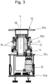
- Fig. 3 shows a vertical cross-sectional view of the central drive unit 10.
- the essentially cylindrical structure of the drive unit 10 comprises cylindrical sections with different diameters.
- a motor 13 preferably a servo motor, is accommodated, which drives a rotor 12 via a planetary gear-pinion arrangement 14.
- a static hollow shaft 11 Radially inward of the rotatable rotor 12 there is a static hollow shaft 11 which has a through-channel 16 extending in the vertical direction.
- the rotor 12 is held on bearings 15 so as to be rotatable about a vertical axis V.
- the rotor 12 also has a flange 10b protruding outwards in the radial direction, which can rotate together with the rotor 12 about the vertical axis V.
- a flange 10b protruding outwards in the radial direction, which can rotate together with the rotor 12 about the vertical axis V.
- the passage channel 16 in the area of the flange 10a can be open, but can also be closed if required with the aid of a Fig. 3 closed with a lid (not shown).
- the through-channel 16 located within the stationary hollow shaft 11 allows the passage of electrical and pneumatic lines to the functional units 50 clamped to the flange.
- the transport units 20, which are rotated about the vertical axis V by the drive unit 10, are preferably clamped to the flange 10b by means of a jaw clamp 20a.
- the upper cross member 39a of the lifting unit 30 is preferably clamped to the flange 10c, while the lower cross member 39b of the lifting unit 30 is preferably clamped to the flange 10d. Only the flange 10b rotates together with the rotor 12 about the vertical axis V, while the flanges 10a, 10c and 10d remain stationary.
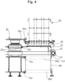
- Fig. 4 shows a partially vertically sectioned view of a portion of the Fig. 1 Filling device 1 shown.
- the upper cross member 39a of the lifting unit 30 is preferably clamped to the flange 10c and the lower cross member 39b of the lifting unit 30 is preferably clamped to the flange 10d.
- Both cross members 39a, 39b are connected to the bottom strut (side cheek) 38.
- the bottom strut 38 is in turn fastened to the support ring 40 via the angle 43.
- the radially inner end of the transport units 20 is preferably clamped to the flange 10b, while the end of the transport unit 20 facing away from the drive unit 10 rests movably on the sliding ring 22.
- the sliding ring 22 is in turn fastened to the plate 41 ( Fig. 2 ) above the support ring 40.
- a functional unit 50 is shown.
- the functional unit 50 shown is a stacking unit in which a large number of cups can be stacked along three vertical columns and individually stacked into the openings 21 of the transport unit 20.
- This functional unit 50 is in turn preferably clamped to the flange 10a of the drive unit 10 via a jaw clamp 50a. This allows all functional units 50 to be attached to the drive unit 10 in a rotationally symmetrical and completely flexible manner.
- a table top as used in the filling systems known from the prior art, is no longer necessary. Due to the lack of a table top, the floor beneath the filling system can be cleaned more easily. Likewise, the The filling system is modular in that it can be adapted to other customer-specific requirements without great effort. Both the lifting unit 30 and any functional unit 50 can be arranged in a variety of angular positions around the drive unit 10. The sequence of the individual process steps from the stacking of individual cups in the transport units 20 to a container discharge unit (not shown) can thus be designed variably.
- a further advantage of the modular design of the filling device 1 according to the invention is that many parts, for example the entire Fig. 2 shown basic structure can be used for different machine sizes, for different transport units 20 and for different filling materials. This allows machines to be pre-assembled independently of the order, which in turn reduces the manufacturing costs.
- the basic structure of the filling device 1 can be used in a largely standardized manner for different machine sizes, different transport units and different arrangements of the functional units 50.
- Another advantage of the filling device 1 according to the invention is that the lack of a table top makes individual components of the filling device 1 easier for the user to access for maintenance and repair work.
- the usability is also improved because the transport units 20 can be arranged at the user's eye level.
- the through-channel 16 provided in the stationary hollow shaft 11 allows electrical and pneumatic lines to be laid centrally through the drive unit 10, which in turn shortens the length of the lines to the functional units 50. Since all electrical and pneumatic drives are sealed within the drive unit 10, and furthermore all movements and other drives are designed to be accessible and cleanable, the risk of contamination, as exists in the prior art due to the vertical movement of the lifting unit 30 through the table top and the associated elevator effects, is reduced to a minimum.
Landscapes
- Engineering & Computer Science (AREA)
- Mechanical Engineering (AREA)
- Basic Packing Technique (AREA)
- Supplying Of Containers To The Packaging Station (AREA)
Applications Claiming Priority (1)
| Application Number | Priority Date | Filing Date | Title |
|---|---|---|---|
| DE102023110385.7A DE102023110385A1 (de) | 2023-04-24 | 2023-04-24 | Vorrichtung vom rundläufer-typ zum abfüllen von einem füllmedium in eine vielzahl von behälter |
Publications (1)
| Publication Number | Publication Date |
|---|---|
| EP4455035A1 true EP4455035A1 (fr) | 2024-10-30 |
Family
ID=90829292
Family Applications (1)
| Application Number | Title | Priority Date | Filing Date |
|---|---|---|---|
| EP24171850.1A Pending EP4455035A1 (fr) | 2023-04-24 | 2024-04-23 | Dispositif du type à carrousel pour remplir un liquide dans une pluralité de récipients |
Country Status (3)
| Country | Link |
|---|---|
| US (1) | US12528688B2 (fr) |
| EP (1) | EP4455035A1 (fr) |
| DE (1) | DE102023110385A1 (fr) |
Citations (3)
| Publication number | Priority date | Publication date | Assignee | Title |
|---|---|---|---|---|
| DE3024271C2 (de) * | 1979-06-29 | 1983-11-24 | Institut de Sérothérapie de Toulouse, S.A., Toulouse | Vorrichtung zum Abfüllen dosierter Füllgutmengen in Behälter |
| DE102014100496B4 (de) * | 2014-01-17 | 2016-05-12 | Khs Gmbh | Behälterbehandlungsmaschine sowie Verfahren zum Behandeln von Behältern |
| DE102017105509A1 (de) * | 2017-03-15 | 2018-09-20 | Khs Gmbh | Verschließmaschine |
Family Cites Families (5)
| Publication number | Priority date | Publication date | Assignee | Title |
|---|---|---|---|---|
| GB8723559D0 (en) * | 1987-10-07 | 1987-11-11 | Glaxo Group Ltd | Machine |
| US5111857A (en) * | 1990-12-20 | 1992-05-12 | Lawarre Precision Technologies, Inc. | Center supply tube for a container filling assembly |
| US5762113A (en) * | 1996-02-23 | 1998-06-09 | Voll Tech Inc. | Volumetric container filling apparatus |
| DE69821008T2 (de) | 1997-04-21 | 2004-11-11 | Graham Packaging Co., L.P. | System zum blasformen, zum füllen und zum kapseln von behältern |
| DE102009041160B4 (de) | 2009-09-14 | 2018-02-22 | Krones Aktiengesellschaft | Vorrichtung zum Herstellen von Flüssigkeitsbehältnissen |
-
2023
- 2023-04-24 DE DE102023110385.7A patent/DE102023110385A1/de active Pending
-
2024
- 2024-04-23 EP EP24171850.1A patent/EP4455035A1/fr active Pending
- 2024-04-23 US US18/643,010 patent/US12528688B2/en active Active
Patent Citations (3)
| Publication number | Priority date | Publication date | Assignee | Title |
|---|---|---|---|---|
| DE3024271C2 (de) * | 1979-06-29 | 1983-11-24 | Institut de Sérothérapie de Toulouse, S.A., Toulouse | Vorrichtung zum Abfüllen dosierter Füllgutmengen in Behälter |
| DE102014100496B4 (de) * | 2014-01-17 | 2016-05-12 | Khs Gmbh | Behälterbehandlungsmaschine sowie Verfahren zum Behandeln von Behältern |
| DE102017105509A1 (de) * | 2017-03-15 | 2018-09-20 | Khs Gmbh | Verschließmaschine |
Also Published As
| Publication number | Publication date |
|---|---|
| KR20240156970A (ko) | 2024-10-31 |
| DE102023110385A1 (de) | 2024-10-24 |
| US12528688B2 (en) | 2026-01-20 |
| US20240351845A1 (en) | 2024-10-24 |
Similar Documents
| Publication | Publication Date | Title |
|---|---|---|
| DE69721321T2 (de) | Verfahren zum handhaben, füllen und verschliessen von verpackungsbehältern | |
| EP0290649B1 (fr) | Dispositif pour remplir en particulier d'une substance liquide ou solide coulante un récipient, plus particulièrement des fûts, fermés avec un bouchon fileté ou un bouchon de fermeture formé d'une autre façon | |
| EP2999635A1 (fr) | Machine de traitement de récipient ainsi que procédé servant à faire fonctionner une machine de traitement de récipient | |
| DE2916338A1 (de) | Vorrichtung zum foerdern und ausrichten von flaschenaehnlichen behaeltern | |
| EP3094590A1 (fr) | Machine de traitement de récipients pour traiter des récipients | |
| EP1134183A1 (fr) | Dispositif de remplissage de bouteilles et récipients similaires de liquides | |
| EP4065911B1 (fr) | Dispositif de traitement pour le traitement de conteneurs pliables | |
| EP2881124B1 (fr) | Dispositif et procédé pour le traitement de petits objets | |
| EP2847123B1 (fr) | Remplisseuse | |
| EP1633663B1 (fr) | Dispositif pour remplir et fermer en continu des emballages en carton/matieres plastiques, ouverts d'un cote, et ensemble cellule servant au transport de tels emballages dans ledit dispositif | |
| DE2145721B2 (de) | Vorrichtung zum Öffnen von dichten und innerlich sterilisierten Behältern aus Kunststoff | |
| DE4415488C2 (de) | System zum Andocken eines Behälters an eine Übergabeöffnung in einem Gerät, Behälter und Gerät | |
| EP3127859B1 (fr) | Procede de remplissage aseptique d'un recipient, dispositif de remplissage sterile correspondant et machine aseptique | |
| DE10261706B4 (de) | Füllmaschine und Verfahren zum Abfüllen von Lebensmitteln | |
| EP4458700A1 (fr) | Dispositif du type à carrousel pour remplir un liquide dans une pluralité de récipients | |
| EP4455036A1 (fr) | Dispositif du type à carrousel pour remplir un liquide dans une pluralité de récipients | |
| DE102023110385A1 (de) | Vorrichtung vom rundläufer-typ zum abfüllen von einem füllmedium in eine vielzahl von behälter | |
| EP3117840A1 (fr) | Recipient de transport et de traitement comprenant une soupape a clapet et procede de vidange d'un tel recipient | |
| DE3134573A1 (de) | "vorrichtung zum wenden von stueckgut" | |
| DE4224003A1 (de) | Vorrichtung zum Füllen und Verschließen von Fließmittelpackungen | |
| EP4201871A1 (fr) | Dispositif de fermeture pour installation de traitement de récipients | |
| DE102023132947A1 (de) | Vorrichtung zum Füllen von Behältern und Verfahren zum Betreiben der Vorrichtung | |
| DE2021723C (de) | Vorrichtung zum Stapeln von Kartons od dgl in vorbestimmbaren Lademustern | |
| EP4516705A1 (fr) | Dispositif de guidage de récipients, système de transport et machine de traitement de récipients comprenant le dispositif | |
| DE1511536C (de) | Verpackungsmaschine fur Flaschen und ähnliche Behalter |
Legal Events
| Date | Code | Title | Description |
|---|---|---|---|
| PUAI | Public reference made under article 153(3) epc to a published international application that has entered the european phase |
Free format text: ORIGINAL CODE: 0009012 |
|
| STAA | Information on the status of an ep patent application or granted ep patent |
Free format text: STATUS: THE APPLICATION HAS BEEN PUBLISHED |
|
| AK | Designated contracting states |
Kind code of ref document: A1 Designated state(s): AL AT BE BG CH CY CZ DE DK EE ES FI FR GB GR HR HU IE IS IT LI LT LU LV MC ME MK MT NL NO PL PT RO RS SE SI SK SM TR |
|
| STAA | Information on the status of an ep patent application or granted ep patent |
Free format text: STATUS: REQUEST FOR EXAMINATION WAS MADE |
|
| 17P | Request for examination filed |
Effective date: 20250415 |