EP4454889A1 - Cleaning device for inkjet print heads and inkjet printer comprising such a device - Google Patents
Cleaning device for inkjet print heads and inkjet printer comprising such a device Download PDFInfo
- Publication number
- EP4454889A1 EP4454889A1 EP24171798.2A EP24171798A EP4454889A1 EP 4454889 A1 EP4454889 A1 EP 4454889A1 EP 24171798 A EP24171798 A EP 24171798A EP 4454889 A1 EP4454889 A1 EP 4454889A1
- Authority
- EP
- European Patent Office
- Prior art keywords
- cleaning device
- print head
- closing element
- supply duct
- abutment surface
- Prior art date
- Legal status (The legal status is an assumption and is not a legal conclusion. Google has not performed a legal analysis and makes no representation as to the accuracy of the status listed.)
- Granted
Links
Images





Classifications
-
- B—PERFORMING OPERATIONS; TRANSPORTING
- B41—PRINTING; LINING MACHINES; TYPEWRITERS; STAMPS
- B41J—TYPEWRITERS; SELECTIVE PRINTING MECHANISMS, i.e. MECHANISMS PRINTING OTHERWISE THAN FROM A FORME; CORRECTION OF TYPOGRAPHICAL ERRORS
- B41J2/00—Typewriters or selective printing mechanisms characterised by the printing or marking process for which they are designed
- B41J2/005—Typewriters or selective printing mechanisms characterised by the printing or marking process for which they are designed characterised by bringing liquid or particles selectively into contact with a printing material
- B41J2/01—Ink jet
- B41J2/135—Nozzles
- B41J2/165—Prevention or detection of nozzle clogging, e.g. cleaning, capping or moistening for nozzles
- B41J2/16517—Cleaning of print head nozzles
- B41J2/16552—Cleaning of print head nozzles using cleaning fluids
-
- B—PERFORMING OPERATIONS; TRANSPORTING
- B41—PRINTING; LINING MACHINES; TYPEWRITERS; STAMPS
- B41J—TYPEWRITERS; SELECTIVE PRINTING MECHANISMS, i.e. MECHANISMS PRINTING OTHERWISE THAN FROM A FORME; CORRECTION OF TYPOGRAPHICAL ERRORS
- B41J2/00—Typewriters or selective printing mechanisms characterised by the printing or marking process for which they are designed
- B41J2/005—Typewriters or selective printing mechanisms characterised by the printing or marking process for which they are designed characterised by bringing liquid or particles selectively into contact with a printing material
- B41J2/01—Ink jet
- B41J2/135—Nozzles
- B41J2/165—Prevention or detection of nozzle clogging, e.g. cleaning, capping or moistening for nozzles
- B41J2/16517—Cleaning of print head nozzles
- B41J2/1652—Cleaning of print head nozzles by driving a fluid through the nozzles to the outside thereof, e.g. by applying pressure to the inside or vacuum at the outside of the print head
-
- B—PERFORMING OPERATIONS; TRANSPORTING
- B41—PRINTING; LINING MACHINES; TYPEWRITERS; STAMPS
- B41J—TYPEWRITERS; SELECTIVE PRINTING MECHANISMS, i.e. MECHANISMS PRINTING OTHERWISE THAN FROM A FORME; CORRECTION OF TYPOGRAPHICAL ERRORS
- B41J2/00—Typewriters or selective printing mechanisms characterised by the printing or marking process for which they are designed
- B41J2/005—Typewriters or selective printing mechanisms characterised by the printing or marking process for which they are designed characterised by bringing liquid or particles selectively into contact with a printing material
- B41J2/01—Ink jet
- B41J2/17—Ink jet characterised by ink handling
- B41J2/175—Ink supply systems ; Circuit parts therefor
Definitions
- the present invention relates to a cleaning device for inkjet print heads.
- the present invention relates to a cleaning device for inkjet print heads both of industrial inkjet printers for large-size formats, so-called inkjet plotters, and of inkjet printers for small-size or reduced formats.
- the present invention also relates to an inkjet printer comprising such a cleaning device.
- Inkjet printing technology used to mark and decorate various surfaces, is well-known in the present state of the art. With said technology it is possible to obtain high-quality print-outs on a wide range of materials rapidly.
- Inkjet printers use a "non-impact" process in order to release the ink onto the surface to be decorated.
- the ink is in fact released from nozzles arranged on a print head which is mounted on a carriage usually movable in a direction transverse to the support on which printing is to be performed.
- the ink may be taken from movable and replaceable containers, so-called cartridges. In the past these cartridges were fixed together with the print head.
- the vacuum which is created inside the connection circuit between tanks and nozzles during the printing operations enables the ink to be sucked out of the various tanks and to be conveyed to the nozzles of the print head.
- a first method for cleaning any ink residues from the nozzles is to disconnect the print head from the printer and immerse it in a cleaning solution. Such a method is described for example in JP2004-358667 .
- the aforementioned method involves, however, a prolonged machine downtime. Moreover, after the cleaning operation, there is the risk that air may remain trapped inside the nozzles or in the connection system which conveys the ink from the tanks to the print head, with negative effects, at least initially, during the first print-outs after cleaning.
- a second method involves using directly the ink contained in the various tanks in order to clean any residues from the nozzles and the connection system. With this method the ink is conveyed under pressure to the print head and the nozzles so as to remove any incrustations.
- the disposal of the cleaning ink has a not insignificant environmental impact.
- this cleaning method stresses the nozzles of the print head, increasing the wear thereof. Finally, during the cleaning operations, the print head may overheat and even break.
- the general object of the present invention is to overcome the drawbacks of the prior art.
- a first task of the present invention is to provide a cleaning device for inkjet print heads, which allows easy and efficient cleaning of the print heads.
- a further task of the present invention is to provide a cleaning device for inkjet print heads, which allows the cleaning operations to be performed in a rapid and efficient manner and with a low environmental impact.
- a task of the present invention is to provide a cleaning device for inkjet print heads, which has small dimensions and a low weight and which may also be used with already existing printers having several colour tanks.
- a task of the present invention is to provide a cleaning device for inkjet print heads, which does not result in stressing of the print heads and which does not require the print head to be disconnected from the printer.
- the aforementioned object and tasks are achieved by a cleaning device for inkjet print heads according to Claim 1 and by an inkjet printer according to Claim 16.
- a cleaning device according to the present invention is denoted overall by the reference number 10.
- said cleaning device 10 is designed to be used in combination both with inkjet printers provided with print heads 100A of the conventional type, shown schematically in Figures 1-3 , 8 and 10 and with inkjet printers provided with ink recirculation print heads 100B, shown schematically in Figures 4-5 and 13-16 .
- a first type of print head 100A of the conventional type comprises a plurality of nozzles 101 (see Figure 1A ) and is mounted on a carriage 102 movable forwards and backwards along a guide 103.
- This print head configuration is commonly referred to in the technical jargon as a "scan" configuration.
- the print head 100A is movable along a direction T, which is usually transverse to the direction of feeding S of the support on which the printing is performed.
- the printing ink is removed from one or more tanks 104 arranged on the outside of the print head 100A and connected thereto by means of a supply system consisting of a plurality of flexible tubes 105.
- These flexible tubes 105 convey the inks to the print heads 100A along the direction of flow C.
- the tubes 105 are connected to respective inlet ports 106 provided in the carriage 102 and in turn connected to the nozzles 101.
- Figure 1 schematically shows a print head 100A provided with four separate tanks 104 and designed, for example, to perform a four-colour print, using the CMYK method.
- cyan, magenta, yellow and black coloured inks will be contained respectively inside the four tanks 104.
- the cleaning device 10 may be used in combination with print heads 100A which also use several base colours, for example 8, 12, 16 or more colours.
- a variant of the print head 100A described above and able to be used with the device 10 according to the present invention comprises a valve 107 with a small storage tank which is removably fixed to the print head 100A and referred to in the technical jargon as a "damper" (see Figure 2 ).
- the damper is usually mounted between the tanks 104 and the print head 100A.
- the function of the damper is to filter and ensure that a minimum amount of ink is always available for the nozzles 101 of the print head 100A such that the piezoelectric actuator is more readily able to respond and release the ink jet onto the support to be printed.
- the printer comprises a printing unit 1000A which is composed of a plurality of print heads 100A positioned adjacent to each other so as to each cover a different portion of the printing area on the support onto which the image must be printed.
- the printing unit 1000A is fixed, while the support is movable along the direction S.
- the system for supplying the inks of the print heads 100A forming the unit 1000A is, for each head 100A, the same as that schematically shown in Figure 1 .
- the configuration shown schematically in Figures is referred to in the technical jargon as a "single-pass" configuration and has the advantage that it allows a high printing speed.
- the cleaning device 10 may advantageously be used also with inkjet printers which have ink recirculation print heads 100B, shown schematically in Figures 4 and 5 for example.
- Ink recirculation print heads 100B are particularly useful for preventing sedimentation of the inks, if they are greatly pigmented, and for reducing the formation of air bubbles in the supply ducts.
- This type of print head 100B comprises two separate connections - an outward connection 105A and a return connection 105B - which are provided between each tank 104 and the print head 100B (see Figure 4 ) or between each tank 104 and the damper 107 (see Figure 5 ).
- the frame 102, or the damper 107 is therefore provided with inlet ports 106 for the connection tubes 105A, by means of which the ink flows inside the print head 100B, or inside the damper 107, along the direction of flow schematically indicated by the arrows C, and with outlet ports 108, by means of which the ink returns from the print head 100B, or the damper 107, to each tank 104 along the direction of flow schematically indicated by the arrows D.
- the ink recirculation print heads 100B may be arranged in the scan configuration (see Figure 4 ), in the configuration with damper 107 (see Figure 5 ) and in the single-pass configuration (not shown, but well-known to the person skilled in the art).
- the device 10 is designed to be advantageously positioned in-line between the tanks 104 and the print head 100A, 100B or between the tanks 104 and the dampers 107, such that the washing process involves in the cleaning process both the print head 100A, 100B and the damper 107, if present.
- the reference number 100A will be used for the print heads of the conventional type and the reference number 100B will be used for the ink recirculation print heads, irrespective as to whether they are in the scan or single-pass configuration and with or without dampers 107.
- the cleaning device 10 comprises a housing 12 and a container for a washing liquid 14.
- the device 10 also comprises at least one first supply duct 16 and at least one second supply duct 18.
- the first supply duct 16 has a first end 16A, designed to be connected to the washing liquid container 14, and a second end 16B, designed to be connected to the print head 100A, 100B.
- the second supply duct 18 has a first end 18A, designed to be connected to a tank 104 for the printing ink, and a second end 18B, designed to be connected to the print head 100A, 100B.
- connections of the supply ducts 16, 18 to the tanks 104, to the washing liquid container 14 and to the print head 100A, 100B may be direct or indirect.
- a further element, such as a damper 107 may be provided between the supply ducts 16, 18 and the print head 100A, 100B.
- the cleaning device 10 according to the invention is therefore intended to be inserted along the connections 105; 105A, 105B between the tanks 104 and the print heads 100A, 100B.
- the second supply duct 18 in fact forms part of the connection 105; 105A, 105B between the tanks 104 and the print head 100A, 100B.
- the first supply duct 18 and the second supply duct 18 are made of an elastically compressible material, where "elastically compressible", for the purposes of the present description, is understood as meaning a material suitable for being deformed when subjected to a compressive force and for recovering substantially its initial form once the compression force ceases.
- the cleaning device 10 is characterized, moreover, in that it comprises at least one closing element 20.
- Said closing element 20 is movable inside the housing 12 between a first position (see Figures 8, 9 , 13, 14 ) and a second position (see Figures 10, 11 , 12 , 15 and 16 ).
- the closing element 20 transversely compresses the first supply duct 16, sealingly closing off a throughflow section thereof, and in said second position, the closing element 20 transversely compresses the second supply duct 19, sealingly closing off a throughflow section thereof.
- the cleaning device 10 allows easy cleaning of the print heads 100A, 100B to which it is connected.
- the first and second supply ducts 16, 18 it is possible to change simply and rapidly the supplying of the print head 100A, 100B from a mode where the print head 100A, 100B is supplied only with the printing ink taken from the various colour tanks 104 to a mode where the print head 100A, 100B is supplied only with the washing liquid taken from the container 14.
- This change-over operation is made possible by the movement of the closing element 20 and by the provision of supply ducts 16, 18 made of elastically compressible material.
- the print head 100A, 100B is supplied only with the printing ink, since the first supply duct 16 is closed, while with the closing element 20 in the second position, the print head 100A, 100B is supplied only with the washing liquid, since the second supply duct 18 is closed.
- the closing element 20 During the normal printing operations the closing element 20 will be in the first position and during the cleaning or washing operations the closing element 20 will be in the second position.
- the cleaning device according to the invention it is advantageously possible to use, both for the print heads of the conventional type and for the ink recirculation print heads, specific cleaning liquids instead of the ink itself, with advantages in terms of cost and efficiency of the cleaning operation.
- the housing 12 may comprise a first abutment surface 22 and a second abutment surface 24 facing each other.
- the closing element 20 when the closing element 20 is located in the first position, it compresses the supply duct 16 against the first abutment surface 22, while in the second position the closing element 20 compresses the second supply duct 18 against the second abutment surface 24.
- the housing 12 has a box-shaped form.
- the first abutment surface 22 and the second abutment surface 24 are rigid opposite walls of said box-shaped housing.
- the housing may be made of metallic or rigid polymer material.
- the housing 12 may be positioned alongside or above the print head 100A, 100B such that it is arranged between the print head 100A, 100B and the tanks 104 for the printing ink.
- the supply ducts 16, 18 and the closing element 20 are positioned inside the housing 12, while the washing liquid container 14 may be positioned outside the housing 12 so as to facilitate the replacement thereof when needed.
- the washing liquid container 14 is preferably supplied by means of a duct (not shown in the attached figures) which connects the container 14 to a tank for the washing liquid positioned close to the ink tanks 104. Supplying of the washing liquid container 14 may be performed by means of gravity or by means of a pump which is designed to be activated in the event where a drop in pressure inside the container 14 is detected.
- the washing liquid container 14 is preferably formed by a flexible bag made of polymer material.
- the flexible bag is made of polypropylene.
- the bag has a rectangular shape.
- the bag 14 when the closing device 20 is in its second position, the bag 14, since it is made of flexible material, may be deflated in a uniform manner such that the washing liquid flows freely towards the print head 100A, 100B, without the need for activation of a sucking action by the piezoelectric actuator and therefore without stressing and subjecting the print head 100A, 100B to wear during the cleaning process.
- the container 14 is provided with at least one outlet 25 and at least one inlet 27.
- the outlet 25 is connected to the first supply duct 16, while the inlet 27 is connected to a washing liquid tank.
- the container 14 may be filled by means of the inlet 27.
- the inlet 27 is preferably provided with a connector 28.
- the outlet 25 may also be provided with a connector 26 intended to be connected directly or indirectly to the first end 16A of the first supply duct 16.
- the container 14 is provided with a plurality of outlets 25.
- the number of said outlets 25 is equal to the number of ink tanks 104 of the print head 100A, 100B.
- the container 14 will therefore be provided with four separate outlets 25, each outlet 25 being connected to a different first supply duct 16.
- the container 14 may also be provided with a plurality of inlets 27.
- the container 14 is provided with two separate inlets 27. In this way, the container 14 may be more easily topped up or filled.
- the first and second supply ducts 16, 18 are preferably made of flexible polymer material.
- the supply ducts 16, 18 are made of elastomer material, for example nitrile butadiene rubber (NBR), styrene-butadiene rubber (SBR), hydrogenated nitrile butadiene rubber (HNBR), fluoroelastomer, silicone, ethylene propylene diene monomer (EPDM) rubber, polyurethane elastomer; in this way they may be easily compressed and at the same time may rapidly recover their initial form once the compressive force acting on them ceases.
- NBR nitrile butadiene rubber
- SBR styrene-butadiene rubber
- HNBR hydrogenated nitrile butadiene rubber
- fluoroelastomer silicone, ethylene propylene diene monomer (EPDM) rubber, polyurethane elastomer
- the size of the throughflow sections of the supply ducts 16, 18 will be chosen depending on the flowrate of ink or washing liquid which must be conveyed to the print head.
- the cleaning device 10 comprises a plurality of first ducts 16 and a plurality of second ducts 18.
- the number of first supply ducts 16 is equal to the number of second supply ducts 18, so as to ensure efficient cleaning of the print head 100A.
- first supply ducts 16 and second supply ducts 18 are equal to the number of ink tanks 14 which supply the print head 100A.
- Figures 8 and 10 show schematically a single second supply duct 18 and a single first supply duct 16.
- the supply ducts 16, 18 are connected to the connection tube 105 by means of which the ink flows from the tank 104 into the print head 100A.
- the device 10 preferably comprises two second supply ducts 118A, 118B for each tank 104: an outward duct 118A and a return duct 118B.
- the outward duct 118A is connected to the connection tube 105A by means of which the ink flows from the tank 104 into the print head 100B and the return duct 118B is connected to the connection tube 105B by means of which the ink returns from the print head 100B to the tank 104.
- a single outward duct 118A is shown in Figures 13 and 15 and a single return duct 118B is shown in Figures 14 and 16 .
- these ducts 118A, 118B are both present simultaneously in the case where the print head is of the ink recirculation type.
- the device 10 comprises preferably, for each tank 104, in addition to a first supply duct 116A, a discharge duct 116B.
- the first supply duct 116A is connected to the connection tube 105A and allows the introduction of the washing liquid taken from the container 14 into the print head 100B.
- the discharge duct 116B is connected to the connection tube 105B and allows the washing liquid output from the print head 100B to be conveyed to a storage tank 114.
- the discharge duct 116B has a first end connected to the connection tube 105B and a second end connected to an outlet duct 125 by means of which the washing liquid is conveyed to the storage tank 114.
- a single first supply duct 116A is shown in Figures 13 and 15 and a single discharge duct 116B is shown in Figures 14 and 16 .
- these ducts are both present simultaneously in the case where the print head is of the ink recirculation type.
- the second end 16B of a first supply duct 16; 116A or of a discharge duct 116B and the second end 18B of a second supply duct 18; 118A, 118B are connected to a single connector 30 in turn intended to be directly or indirectly connected to the print head 100A, 100B by means of an outlet duct 105A, 105B.
- the connector 30 is a Y-shaped connector, with the two inlets respectively connected to the second end 16B of the first supply duct 16; 116A and to the second end 18B of the second supply duct 18; 118A, 118B and with the outlet connected to the outlet duct 105A, 105B.
- the connector 30 is preferably made of polymer material, for example polypropylene, polyethylene or polytetrafluoroethylene.
- the cleaning device 10 will be provided with a number of connectors 30 equal to the number of first and second supply ducts 16, 18; 116A, 118A, 118B.
- the closing element 20 is advantageously movable along a guide rail 34.
- the guide rail 34 is arranged perpendicularly with respect to the first abutment surface 22 and to the second abutment surface 24.
- the closing element 20 and the guide rail 34 define a transmission coupling of the worm screw/female thread type, wherein the closing element 20 corresponds to the female thread and the guide rail 34 corresponds to the worm screw.
- the worm screw 24 is provided with an external thread intended to engage with a corresponding internal thread of the closing element 20 mounted thereon.
- the pitch and the inclination of the external thread of the worm screw 34 and the pitch and the inclination of the internal thread of the closing element 20 may be selected so as to form an irreversible coupling, i.e. a coupling in which the closing element 20 remains locked on the worm screw 34 when the worm screw 34 is stationary, i.e. is not rotated.
- the closing element 20 has preferably a cylindrical shape with its longitudinal axis arranged perpendicularly with respect to the guide rail 34 and parallel to the direction along which the first abutment surface 22 and the second abutment surface 24 extend.
- the guide rail 34 is connected to a drive motor 36 which is preferably arranged outside of the housing 12.
- the drive motor 36 may be an electric motor.
- the closing element 20 may maintain its first position or its second position, without the motor 26 being continuously powered.
- the electric motor 36 may be operated by means of a control device of the known type - not shown in the attached figures - which may cause reversal of the rotary movement of the screw 34 so as to allow the movement of the closing element 20 in either direction.
- the closing element 20 is coupled to a single guide rail 34 positioned in a central portion of the closing element 20 (see Figures 9 and 11 ).
- This solution is preferably adopted in the case where the print head 100 is supplied with 4, 6 or 8 colours.
- the closing element 20 is preferably coupled to two guide rails 34 which are positioned along the side portions of the closing element 20.
- the two guide rails 34 will be operated by two separate drive motors 36 (see Figure 12 ).
- the cleaning device 10 is connected to a print head 100A of the conventional type, which is provided with a plurality of nozzles 101 and which uses the CMYK printing method and is therefore supplied with ink taken from four separate tanks 104.
- These tanks in accordance with that shown in Figures 1 , 2 , 4 and 5 , are positioned outside the print head 100A.
- the cleaning device 10 during use is intended to be arranged between the print head 100A provided with a plurality of nozzles, and the ink tanks 104.
- the cleaning device is provided with four first supply ducts 16 and with four second supply ducts 18.
- first ends 16A of each of the first supply ducts 16 are connected to the washing liquid container 14 at each outlet 27 and the second ends 16B of each of the second supply ducts are connected to a different connector 30.
- first ends 18A of each of the second supply ducts 18 are connected to a different ink tank 104 and the second ends 18B of each of the second supply ducts 18 are connected to a different connector 30.
- the closing element 20 is located in its first position (see Figures 8 and 9 ).
- the closing element 20 transversely compresses each of the first supply ducts 16 against the first abutment surface 22, sealingly closing off the respective throughflow sections.
- the washing liquid contained in the bag 14 is therefore blocked along the sections of the first supply ducts 16 closed by the closing element 20.
- the print head 100A is supplied solely with the ink taken from the various colour tanks via the second supply ducts 18.
- the closing element 20 When it is required to clean the nozzles, by starting the drive motor 36 the closing element 20 may be moved along the worm screw 34, so as to pass from its first position into its second position.
- the closing element 20 may transversely compress each of the second supply ducts 16 against the second abutment surface 22, sealingly closing the respective throughflow sections.
- the ink contained in each of the four tanks 104 is therefore blocked along the sections of the second supply ducts 18 closed by the closing element 20.
- the closing element 20 no longer compresses the first supply ducts 16 and therefore the washing liquid contained inside them may flow towards the print head 100A.
- the print head 100A is therefore supplied solely with the washing liquid taken from the bag 14 via the first supply ducts.
- the washing liquid may be conveyed to all the nozzles of the print head, thereby performing cleaning thereof.
- the closing element 20 may be brought back into its first position, so as to compress and block the flow of the washing liquid towards the print head and at the same time allow the latter to be supplied again with the ink taken from the tanks 104.
- the cleaning device 10 is provided with two second supply ducts 118A, 118B for each colour tank 104.
- the cleaning device 10 also is provided with a first supply duct 116A and a discharge duct 116B.
- the closing element 20 transversely compresses at least the first supply duct 116A.
- the closing element 20 may transversely compress also the discharge duct 116B.
- the closing element 20 transversely compresses the outward duct 118A and the return duct 118B for the ink.
- the ink via the outward duct 118A may flow inside the print head 100B (see Figure 13 ) and via the return duct 118B it may return from the print head 100B to the tank 104 (see Figure 14 ).
- the washing liquid is in fact blocked by the closing element.
- the washing liquid output from the print head may be conveyed via the discharge duct 116B to the storage tank 114 so as to prevent the washing liquid from contaminating the ink tank 104 (see Figure 16 ).
- the cleaning device according to the invention is in fact able to ensure easy and efficient cleaning of the print head.
- the printing inks which are being used inside the print head may be replaced with a washing liquid without the introduction of air and/or having to disconnect the existing connections.
- the cleaning device moreover, is compact and has a limited weight and dimensions and may also be used in combination with print heads which are already installed and in use. It is sufficient to disconnect the tanks from the print head and connect the outlets of the tanks to the second supply ducts of the cleaning device on the one hand and, on the other hand, connect the outlet ducts of the device to the print head. Furthermore, the cleaning device according to the invention, owing to the flexible washing liquid container, does not subject the piezoelectric actuator of the print head to a stressing force during the cleaning operations and this allows the working life thereof to be increased.
- the possibility of cleaning the print head without, in fact, disconnecting it from the ink tanks and via the Y connectors ensures that no air is introduced inside the supply circuit, even in the case of ink recirculation heads, thus ensuring a high printing quality.
Landscapes
- Ink Jet (AREA)
Abstract
Description
- The present invention relates to a cleaning device for inkjet print heads. In particular, the present invention relates to a cleaning device for inkjet print heads both of industrial inkjet printers for large-size formats, so-called inkjet plotters, and of inkjet printers for small-size or reduced formats.
- The present invention also relates to an inkjet printer comprising such a cleaning device.
- Inkjet printing technology, used to mark and decorate various surfaces, is well-known in the present state of the art. With said technology it is possible to obtain high-quality print-outs on a wide range of materials rapidly.
- Inkjet printers use a "non-impact" process in order to release the ink onto the surface to be decorated. The ink is in fact released from nozzles arranged on a print head which is mounted on a carriage usually movable in a direction transverse to the support on which printing is to be performed.
- In some types of inkjet printers the ink may be taken from movable and replaceable containers, so-called cartridges. In the past these cartridges were fixed together with the print head.
- For some time, however, the use of external tanks, i.e. one for each colour, connected to the print head by means of flexible tubes, has become increasingly widespread.
- The vacuum which is created inside the connection circuit between tanks and nozzles during the printing operations enables the ink to be sucked out of the various tanks and to be conveyed to the nozzles of the print head.
- This solution, while being favourably regarded, poses problems during the cleaning operations which must be carried out on the nozzles.
- A first method for cleaning any ink residues from the nozzles is to disconnect the print head from the printer and immerse it in a cleaning solution. Such a method is described for example in
JP2004-358667 - The aforementioned method involves, however, a prolonged machine downtime. Moreover, after the cleaning operation, there is the risk that air may remain trapped inside the nozzles or in the connection system which conveys the ink from the tanks to the print head, with negative effects, at least initially, during the first print-outs after cleaning.
- A second method involves using directly the ink contained in the various tanks in order to clean any residues from the nozzles and the connection system. With this method the ink is conveyed under pressure to the print head and the nozzles so as to remove any incrustations.
- It is obvious that this procedure involves not insignificant costs since the inkjet ink itself has a high cost and, if used for the cleaning operations, is in fact mostly wasted instead of being used for printing.
- Moreover, the disposal of the cleaning ink has a not insignificant environmental impact.
- Furthermore, this cleaning method stresses the nozzles of the print head, increasing the wear thereof. Finally, during the cleaning operations, the print head may overheat and even break.
- The general object of the present invention is to overcome the drawbacks of the prior art.
- In particular, a first task of the present invention is to provide a cleaning device for inkjet print heads, which allows easy and efficient cleaning of the print heads.
- A further task of the present invention is to provide a cleaning device for inkjet print heads, which allows the cleaning operations to be performed in a rapid and efficient manner and with a low environmental impact.
- Furthermore, a task of the present invention is to provide a cleaning device for inkjet print heads, which has small dimensions and a low weight and which may also be used with already existing printers having several colour tanks.
- Finally, a task of the present invention is to provide a cleaning device for inkjet print heads, which does not result in stressing of the print heads and which does not require the print head to be disconnected from the printer.
- The aforementioned object and tasks are achieved by a cleaning device for inkjet print heads according to
Claim 1 and by an inkjet printer according toClaim 16. - The characteristic features and further advantages of the invention will emerge from the description, provided hereinbelow, of a number of examples of embodiment, provided by way of a non-limiting example, with reference to the accompanying drawings in which:
-
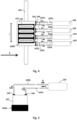
Figure 1 shows a schematic view, from below, of a known type of inkjet print head which can be used in combination with the device according to the present invention; -
Figure 1A shows a view, on a larger scale, of a detail of the print head ofFigure 1 ; -
Figure 2 shows a schematic side view of a further type of print head which can be used with the device of the present invention; -
Figure 3 shows a schematic view, from below, of a different type of inkjet print head which can be used in combination with the device according to the present invention; -
Figures 4 and 5 are similar toFigures 1 and2 , respectively, and show schematically further types of print head which can be used in combination with the device according to the present invention; -
Figure 6 shows a schematic view, from above, of a first component of the cleaning device according to the invention; -
Figure 7 shows a side view ofFigure 6 ; -
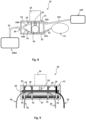
Figure 8 shows a schematic side view of the cleaning device according to the invention in a first operative configuration; -
Figure 9 shows a front view of the cleaning device according toFigure 8 ; -
Figure 10 shows a view, similar toFigure 8 , in which the cleaning device according to the invention is in a second operative configuration; -
Figure 11 shows a front view of the cleaning device according toFigure 10 ; -
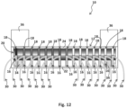
Figure 12 shows a view similar toFigure 11 , but relating to a different embodiment of the cleaning device according to the invention; -
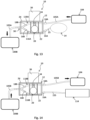
Figures 13 and 14 are views similar toFigure 8 , but relating to a different embodiment with the cleaning device according to the invention in a first operative configuration; -
Figures 15 and 16 are views which are similar toFigures 13 and 14 , respectively, but in which the cleaning device according to the invention is in a second operative configuration; - With reference to the attached figures, a cleaning device according to the present invention is denoted overall by the
reference number 10. - Advantageously, said
cleaning device 10 is designed to be used in combination both with inkjet printers provided withprint heads 100A of the conventional type, shown schematically inFigures 1-3 ,8 and10 and with inkjet printers provided with inkrecirculation print heads 100B, shown schematically inFigures 4-5 and13-16 . - As shown in
Figure 1 , a first type ofprint head 100A of the conventional type comprises a plurality of nozzles 101 (seeFigure 1A ) and is mounted on a carriage 102 movable forwards and backwards along aguide 103. - This print head configuration is commonly referred to in the technical jargon as a "scan" configuration.
- In particular, the
print head 100A is movable along a direction T, which is usually transverse to the direction of feeding S of the support on which the printing is performed. - The printing ink is removed from one or
more tanks 104 arranged on the outside of theprint head 100A and connected thereto by means of a supply system consisting of a plurality offlexible tubes 105. Theseflexible tubes 105, as shown inFigure 1 , convey the inks to theprint heads 100A along the direction of flow C. Thetubes 105 are connected torespective inlet ports 106 provided in the carriage 102 and in turn connected to thenozzles 101. -
Figure 1 schematically shows aprint head 100A provided with fourseparate tanks 104 and designed, for example, to perform a four-colour print, using the CMYK method. In this case, cyan, magenta, yellow and black coloured inks will be contained respectively inside the fourtanks 104. - Advantageously, however, as will be explained in detail below, the
cleaning device 10 according to the present invention may be used in combination withprint heads 100A which also use several base colours, for example 8, 12, 16 or more colours. - A variant of the
print head 100A described above and able to be used with thedevice 10 according to the present invention comprises avalve 107 with a small storage tank which is removably fixed to theprint head 100A and referred to in the technical jargon as a "damper" (seeFigure 2 ). - The damper is usually mounted between the
tanks 104 and theprint head 100A. - The function of the damper is to filter and ensure that a minimum amount of ink is always available for the
nozzles 101 of theprint head 100A such that the piezoelectric actuator is more readily able to respond and release the ink jet onto the support to be printed. - A further variant of the type of
print head 100A described above is shown inFigure 3 . In this variant, the printer comprises aprinting unit 1000A which is composed of a plurality ofprint heads 100A positioned adjacent to each other so as to each cover a different portion of the printing area on the support onto which the image must be printed. - In this case the
printing unit 1000A is fixed, while the support is movable along the direction S. - The system for supplying the inks of the
print heads 100A forming theunit 1000A is, for eachhead 100A, the same as that schematically shown inFigure 1 . - The configuration shown schematically in Figures is referred to in the technical jargon as a "single-pass" configuration and has the advantage that it allows a high printing speed.
- As mentioned above, the
cleaning device 10 according to the present invention may advantageously be used also with inkjet printers which have inkrecirculation print heads 100B, shown schematically inFigures 4 and 5 for example. - Ink
recirculation print heads 100B are particularly useful for preventing sedimentation of the inks, if they are greatly pigmented, and for reducing the formation of air bubbles in the supply ducts. - This type of
print head 100B comprises two separate connections - anoutward connection 105A and areturn connection 105B - which are provided between eachtank 104 and theprint head 100B (seeFigure 4 ) or between eachtank 104 and the damper 107 (seeFigure 5 ). - The frame 102, or the
damper 107, is therefore provided withinlet ports 106 for theconnection tubes 105A, by means of which the ink flows inside theprint head 100B, or inside thedamper 107, along the direction of flow schematically indicated by the arrows C, and withoutlet ports 108, by means of which the ink returns from theprint head 100B, or thedamper 107, to eachtank 104 along the direction of flow schematically indicated by the arrows D. - The ink recirculation print heads 100B may be arranged in the scan configuration (see
Figure 4 ), in the configuration with damper 107 (seeFigure 5 ) and in the single-pass configuration (not shown, but well-known to the person skilled in the art). - As will become clear from the description below, the
device 10 is designed to be advantageously positioned in-line between thetanks 104 and theprint head tanks 104 and thedampers 107, such that the washing process involves in the cleaning process both theprint head damper 107, if present. - For the sake of convenience below the
reference number 100A will be used for the print heads of the conventional type and thereference number 100B will be used for the ink recirculation print heads, irrespective as to whether they are in the scan or single-pass configuration and with or withoutdampers 107. - With reference to
Figures 8-16 , thecleaning device 10 according to the invention comprises ahousing 12 and a container for awashing liquid 14. - The
device 10 also comprises at least onefirst supply duct 16 and at least onesecond supply duct 18. - The
first supply duct 16 has afirst end 16A, designed to be connected to thewashing liquid container 14, and asecond end 16B, designed to be connected to theprint head - The
second supply duct 18, in turn, has afirst end 18A, designed to be connected to atank 104 for the printing ink, and asecond end 18B, designed to be connected to theprint head - The connections of the
supply ducts tanks 104, to thewashing liquid container 14 and to theprint head damper 107 may be provided between thesupply ducts print head - The
cleaning device 10 according to the invention is therefore intended to be inserted along theconnections 105; 105A, 105B between thetanks 104 and the print heads 100A, 100B. - The
second supply duct 18 in fact forms part of theconnection 105; 105A, 105B between thetanks 104 and theprint head - In accordance with the invention, the
first supply duct 18 and thesecond supply duct 18 are made of an elastically compressible material, where "elastically compressible", for the purposes of the present description, is understood as meaning a material suitable for being deformed when subjected to a compressive force and for recovering substantially its initial form once the compression force ceases. - The
cleaning device 10 is characterized, moreover, in that it comprises at least oneclosing element 20. Said closingelement 20 is movable inside thehousing 12 between a first position (seeFigures 8, 9 ,13, 14 ) and a second position (seeFigures 10, 11 ,12 ,15 and 16 ). - In particular, in said first position, the closing
element 20 transversely compresses thefirst supply duct 16, sealingly closing off a throughflow section thereof, and in said second position, the closingelement 20 transversely compresses the second supply duct 19, sealingly closing off a throughflow section thereof. - As will become clear from the description below, the
cleaning device 10 according to the invention allows easy cleaning of the print heads 100A, 100B to which it is connected. In fact, owing to the possibility of closing, alternately, the first andsecond supply ducts print head print head various colour tanks 104 to a mode where theprint head container 14. - This change-over operation is made possible by the movement of the
closing element 20 and by the provision ofsupply ducts - In fact, with the closing
element 20 in the first position, theprint head first supply duct 16 is closed, while with the closingelement 20 in the second position, theprint head second supply duct 18 is closed. - During the normal printing operations the closing
element 20 will be in the first position and during the cleaning or washing operations the closingelement 20 will be in the second position. - Moreover, with the cleaning device according to the invention it is advantageously possible to use, both for the print heads of the conventional type and for the ink recirculation print heads, specific cleaning liquids instead of the ink itself, with advantages in terms of cost and efficiency of the cleaning operation.
- Finally, by using suitably formulated cleaning liquids, the wear of the inkjet head is reduced and consequently there is less risk of breakage thereof.
- With reference to the attached figures, the
housing 12 may comprise afirst abutment surface 22 and asecond abutment surface 24 facing each other. Preferably, when theclosing element 20 is located in the first position, it compresses thesupply duct 16 against thefirst abutment surface 22, while in the second position the closingelement 20 compresses thesecond supply duct 18 against thesecond abutment surface 24. - Advantageously, the
housing 12 has a box-shaped form. Preferably, thefirst abutment surface 22 and thesecond abutment surface 24 are rigid opposite walls of said box-shaped housing. - The housing may be made of metallic or rigid polymer material.
- As will be explained below, the
housing 12 may be positioned alongside or above theprint head print head tanks 104 for the printing ink. - Advantageously, the
supply ducts closing element 20 are positioned inside thehousing 12, while the washingliquid container 14 may be positioned outside thehousing 12 so as to facilitate the replacement thereof when needed. - The washing
liquid container 14 is preferably supplied by means of a duct (not shown in the attached figures) which connects thecontainer 14 to a tank for the washing liquid positioned close to theink tanks 104. Supplying of the washingliquid container 14 may be performed by means of gravity or by means of a pump which is designed to be activated in the event where a drop in pressure inside thecontainer 14 is detected. - With reference to
Figures 6 and 7 , the washingliquid container 14 is preferably formed by a flexible bag made of polymer material. Advantageously, the flexible bag is made of polypropylene. - Preferably, the bag has a rectangular shape.
- Advantageously, when the
closing device 20 is in its second position, thebag 14, since it is made of flexible material, may be deflated in a uniform manner such that the washing liquid flows freely towards theprint head print head - The
container 14 is provided with at least oneoutlet 25 and at least oneinlet 27. When thecontainer 14 is in use, theoutlet 25 is connected to thefirst supply duct 16, while theinlet 27 is connected to a washing liquid tank. Thecontainer 14 may be filled by means of theinlet 27. Theinlet 27 is preferably provided with aconnector 28. - Advantageously, the
outlet 25 may also be provided with aconnector 26 intended to be connected directly or indirectly to thefirst end 16A of thefirst supply duct 16. - Preferably, the
container 14 is provided with a plurality ofoutlets 25. The number of saidoutlets 25 is equal to the number ofink tanks 104 of theprint head print head container 14 will therefore be provided with fourseparate outlets 25, eachoutlet 25 being connected to a differentfirst supply duct 16. - Advantageously, as shown schematically in
Figures 6 and 7 , thecontainer 14 may also be provided with a plurality ofinlets 27. Preferably, thecontainer 14 is provided with twoseparate inlets 27. In this way, thecontainer 14 may be more easily topped up or filled. - The first and
second supply ducts supply ducts - The size of the throughflow sections of the
supply ducts - Advantageously, the
cleaning device 10 comprises a plurality offirst ducts 16 and a plurality ofsecond ducts 18. - Preferably, in the print heads of the
conventional type 100A, the number offirst supply ducts 16 is equal to the number ofsecond supply ducts 18, so as to ensure efficient cleaning of theprint head 100A. - Consequently, the number of
first supply ducts 16 andsecond supply ducts 18 is equal to the number ofink tanks 14 which supply theprint head 100A. For the sake of convenience,Figures 8 and10 show schematically a singlesecond supply duct 18 and a singlefirst supply duct 16. - The
supply ducts connection tube 105 by means of which the ink flows from thetank 104 into theprint head 100A. - In the ink recirculation print heads 100B the
device 10 preferably comprises twosecond supply ducts outward duct 118A and areturn duct 118B. - The
outward duct 118A is connected to theconnection tube 105A by means of which the ink flows from thetank 104 into theprint head 100B and thereturn duct 118B is connected to theconnection tube 105B by means of which the ink returns from theprint head 100B to thetank 104. - For the sake of convenience, a single
outward duct 118A is shown inFigures 13 and15 and asingle return duct 118B is shown inFigures 14 and16 . However, theseducts - In the ink recirculation print heads 100B the
device 10 comprises preferably, for eachtank 104, in addition to afirst supply duct 116A, adischarge duct 116B. - The
first supply duct 116A is connected to theconnection tube 105A and allows the introduction of the washing liquid taken from thecontainer 14 into theprint head 100B. - The
discharge duct 116B is connected to theconnection tube 105B and allows the washing liquid output from theprint head 100B to be conveyed to astorage tank 114. In particular thedischarge duct 116B has a first end connected to theconnection tube 105B and a second end connected to anoutlet duct 125 by means of which the washing liquid is conveyed to thestorage tank 114. - For the sake of convenience, a single
first supply duct 116A is shown inFigures 13 and15 and asingle discharge duct 116B is shown inFigures 14 and16 . However, these ducts are both present simultaneously in the case where the print head is of the ink recirculation type. - As schematically shown in the attached figures, preferably the
second end 16B of afirst supply duct 16; 116A or of adischarge duct 116B and thesecond end 18B of asecond supply duct 18; 118A, 118B are connected to asingle connector 30 in turn intended to be directly or indirectly connected to theprint head outlet duct - Preferably, the
connector 30 is a Y-shaped connector, with the two inlets respectively connected to thesecond end 16B of thefirst supply duct 16; 116A and to thesecond end 18B of thesecond supply duct 18; 118A, 118B and with the outlet connected to theoutlet duct - The
connector 30 is preferably made of polymer material, for example polypropylene, polyethylene or polytetrafluoroethylene. - The
cleaning device 10 will be provided with a number ofconnectors 30 equal to the number of first andsecond supply ducts - As shown in the attached figures, the closing
element 20 is advantageously movable along aguide rail 34. - Preferably, the
guide rail 34 is arranged perpendicularly with respect to thefirst abutment surface 22 and to thesecond abutment surface 24. - Advantageously, the closing
element 20 and theguide rail 34 define a transmission coupling of the worm screw/female thread type, wherein theclosing element 20 corresponds to the female thread and theguide rail 34 corresponds to the worm screw. - Consequently, a rotational movement of the
worm screw 34, depending on the direction of rotation of theworm screw 34, results in a movement of theclosing element 20 towards thefirst abutment surface 22 or towards thesecond abutment surface 24 of thehousing 12. - With reference to the coupling of the
worm screw 34 with the closingelement 20 it is known that theworm screw 24 is provided with an external thread intended to engage with a corresponding internal thread of theclosing element 20 mounted thereon. - Advantageously, the pitch and the inclination of the external thread of the
worm screw 34 and the pitch and the inclination of the internal thread of theclosing element 20 may be selected so as to form an irreversible coupling, i.e. a coupling in which theclosing element 20 remains locked on theworm screw 34 when theworm screw 34 is stationary, i.e. is not rotated. - As shown in the attached figures, the closing
element 20 has preferably a cylindrical shape with its longitudinal axis arranged perpendicularly with respect to theguide rail 34 and parallel to the direction along which thefirst abutment surface 22 and thesecond abutment surface 24 extend. - Advantageously, the
guide rail 34 is connected to adrive motor 36 which is preferably arranged outside of thehousing 12. - The
drive motor 36 may be an electric motor. - Advantageously, in the case where the coupling between the closing
element 20 and theworm screw 34 is of the irreversible type, the closingelement 20 may maintain its first position or its second position, without themotor 26 being continuously powered. Theelectric motor 36 may be operated by means of a control device of the known type - not shown in the attached figures - which may cause reversal of the rotary movement of thescrew 34 so as to allow the movement of theclosing element 20 in either direction. - Preferably, the closing
element 20 is coupled to asingle guide rail 34 positioned in a central portion of the closing element 20 (seeFigures 9 and11 ). - This solution is preferably adopted in the case where the print head 100 is supplied with 4, 6 or 8 colours.
- In the case where the print head 100 is supplied with a greater number of colours, for example 16 colours, or the diameter of the
supply ducts element 20 is preferably coupled to twoguide rails 34 which are positioned along the side portions of theclosing element 20. - In this case, the two
guide rails 34 will be operated by two separate drive motors 36 (seeFigure 12 ). - Below the operation of the
cleaning device 10, and in particular how it allows easy cleaning of theprint head - Below reference will be made to the embodiment shown in
Figures 8-11 , it being assumed that thecleaning device 10 is connected to aprint head 100A of the conventional type, which is provided with a plurality ofnozzles 101 and which uses the CMYK printing method and is therefore supplied with ink taken from fourseparate tanks 104. These tanks, in accordance with that shown inFigures 1 ,2 ,4 and 5 , are positioned outside theprint head 100A. - The comments made below are valid, however, also in the case where the print head is connected to a greater number of ink tanks or in the case where the
print head 100B is of the ink recirculation type. - As shown in
Figures 8-11 , thecleaning device 10 during use is intended to be arranged between theprint head 100A provided with a plurality of nozzles, and theink tanks 104. - In accordance with that described above, the cleaning device is provided with four
first supply ducts 16 and with foursecond supply ducts 18. - In particular, the first ends 16A of each of the
first supply ducts 16 are connected to thewashing liquid container 14 at eachoutlet 27 and the second ends 16B of each of the second supply ducts are connected to adifferent connector 30. - Similarly, the first ends 18A of each of the
second supply ducts 18 are connected to adifferent ink tank 104 and the second ends 18B of each of thesecond supply ducts 18 are connected to adifferent connector 30. - During the normal use of the print head, the closing
element 20 is located in its first position (seeFigures 8 and 9 ). - In this position, the closing
element 20 transversely compresses each of thefirst supply ducts 16 against thefirst abutment surface 22, sealingly closing off the respective throughflow sections. The washing liquid contained in thebag 14 is therefore blocked along the sections of thefirst supply ducts 16 closed by the closingelement 20. - In this position, the
print head 100A is supplied solely with the ink taken from the various colour tanks via thesecond supply ducts 18. - When it is required to clean the nozzles, by starting the
drive motor 36 theclosing element 20 may be moved along theworm screw 34, so as to pass from its first position into its second position. - In this way, the closing
element 20 may transversely compress each of thesecond supply ducts 16 against thesecond abutment surface 22, sealingly closing the respective throughflow sections. The ink contained in each of the fourtanks 104 is therefore blocked along the sections of thesecond supply ducts 18 closed by the closingelement 20. - At the same time, the closing
element 20 no longer compresses thefirst supply ducts 16 and therefore the washing liquid contained inside them may flow towards theprint head 100A. - In this position, the
print head 100A is therefore supplied solely with the washing liquid taken from thebag 14 via the first supply ducts. - By means of the
connectors 30 and theoutlet channels 32 the washing liquid may be conveyed to all the nozzles of the print head, thereby performing cleaning thereof. - In the case where cleaning of the print head requires a large amount of washing liquid, via the
inlets 27 it is possible to top up the bag without disconnecting it from the second supply ducts. - Once the cleaning operation has been completed, by starting the
drive motor 36, the closingelement 20 may be brought back into its first position, so as to compress and block the flow of the washing liquid towards the print head and at the same time allow the latter to be supplied again with the ink taken from thetanks 104. - In the case of ink recirculation print heads 100B, as mentioned, the
cleaning device 10 is provided with twosecond supply ducts colour tank 104. Thecleaning device 10 also is provided with afirst supply duct 116A and adischarge duct 116B. - In the first position (see
Figures 13 and 14 ), the closingelement 20 transversely compresses at least thefirst supply duct 116A. Advantageously, in the first position the closingelement 20 may transversely compress also thedischarge duct 116B. - In the second position (see
Figures 15 and 16 ), the closingelement 20 transversely compresses theoutward duct 118A and thereturn duct 118B for the ink. - In this way, in a similar manner to that described above, in the first position of the closing element, the ink via the
outward duct 118A may flow inside theprint head 100B (seeFigure 13 ) and via thereturn duct 118B it may return from theprint head 100B to the tank 104 (seeFigure 14 ). The washing liquid is in fact blocked by the closing element. - In the second position of the closing element, the
outward ducts 118A and thereturn ducts 118B will be blocked and the washing liquid taken from the container via thefirst supply duct 116A may flow into the print head (seeFigure 15 ). - The washing liquid output from the print head may be conveyed via the
discharge duct 116B to thestorage tank 114 so as to prevent the washing liquid from contaminating the ink tank 104 (seeFigure 16 ). - It is now clear how the predefined objects have been achieved.
- The cleaning device according to the invention is in fact able to ensure easy and efficient cleaning of the print head. In a few seconds, in fact, the printing inks which are being used inside the print head may be replaced with a washing liquid without the introduction of air and/or having to disconnect the existing connections. In fact, it is sufficient to operate the closing element drive motor so as to move the closing element from its first position into its second position.
- Owing to the direct flushing of the print head with the washing liquid it is also possible to reduce the machine downtime and also the environmental impact is limited since there is no wastage of ink or other material which requires special attention in order to be disposed of.
- The cleaning device, moreover, is compact and has a limited weight and dimensions and may also be used in combination with print heads which are already installed and in use. It is sufficient to disconnect the tanks from the print head and connect the outlets of the tanks to the second supply ducts of the cleaning device on the one hand and, on the other hand, connect the outlet ducts of the device to the print head. Furthermore, the cleaning device according to the invention, owing to the flexible washing liquid container, does not subject the piezoelectric actuator of the print head to a stressing force during the cleaning operations and this allows the working life thereof to be increased.
- Finally, the possibility of cleaning the print head without, in fact, disconnecting it from the ink tanks and via the Y connectors ensures that no air is introduced inside the supply circuit, even in the case of ink recirculation heads, thus ensuring a high printing quality.
- Obviously the description given above of embodiments applying the innovative principles of the present invention is provided by way of example of these innovative principles and must therefore not be regarded as limiting the scope of the rights claimed herein. In particular, the characteristic features of the various solutions shown here may be combined with each other according to specific needs and wishes, as may now be easily imagined by the person skilled in the art.
- Finally, the exact forms and proportions of the various parts may vary depending on the specific practical requirements.
Claims (19)
- Cleaning device (10) for inkjet print heads (100A, 100B), comprising:- a housing (12);- a container (14) for a washing liquid;- at least one first supply duct (16, 116A) having a first end (16A) designed to be connected to the washing liquid container (14) and a second end (16B) designed to be connected to the print head (100A, 100B);- at least one second supply duct (18; 118A, 118B) having a first end (18A) designed to be connected to a printing ink tank (104) and a second end (18B) designed to be connected to the print head (100A, 100B);wherein said at least one first supply duct (16, 116A) and said at least one second supply duct (18; 118A, 118B) are made of an elastically compressible material and wherein the cleaning device (10) comprises at least one closing element (20) movable inside the housing (12) between a first position, in which the closing element (20) transversely compresses said at least one first supply duct (16, 116A), sealingly closing off a throughflow section of said at least one first supply duct (16, 116A), and a second position, in which the closing element (20) transversely compresses said at least one second supply duct (18; 118A, 118B), sealingly closing off a throughflow section of said at least one second supply duct (18; 118A, 118B).
- Cleaning device (10) according to Claim 1, characterized in that said housing (12) comprise a first abutment surface (22) and a second abutment surface (24) facing each other, in said first position the closing element (20) compressing said at least one first supply duct (16; 116A) against said first abutment surface (22) and in said second position the closing element (20) compressing said at least one second supply duct (18; 118A, 118B) against said second abutment surface (24).
- Cleaning device (10) according to Claim 2, characterized in that the housing (12) is box-shaped, said first abutment surface (22) and said second abutment surface (24) being two opposite walls of said box-shaped housing (12).
- Cleaning device (10) according to any one of the preceding claims, characterized in that the closing element (20) is movable along a guide rail (34).
- Cleaning device (10) according to Claim 4, characterized in that the guide rail (34) is arranged perpendicularly with respect to said first abutment surface (22) and said second abutment surface (24).
- Cleaning device (10) according to Claim 4, characterized in that the closing element (20) and the guide rail (34) define a transmission coupling of the worm screw/female thread type in which the closing element (20) corresponds to the female thread and the guide rail (34) corresponds to the worm screw.
- Cleaning device (10) according to Claim 6, characterized in that a rotational movement of the worm screw (34), depending on the direction of rotation of the worm screw (34), results in a movement of the closing element (20) towards the first abutment surface (22) or towards the second abutment surface (24) of the housing (12).
- Cleaning device (10) according to Claim 2, characterized in that the closing element (20) is movable along a guide rail (34); the closing element (20) having a cylindrical shape with its longitudinal axis arranged perpendicularly with respect to the guide rail (34) and parallel to the direction along which the first abutment surface (22) and the second abutment surface (24) extend.
- Cleaning device (10) according to any one of the preceding claims, characterized in that the washing liquid container (14) is a flexible bag; said flexible bag being preferably made of polymer material.
- Cleaning device (10) according to any one of the preceding claims, characterized in that said washing liquid container (14) is provided with at least one outlet (25) and with at least one inlet (27); said at least one outlet (25) being intended to be connected to said at least one first supply duct (16; 116A) and said at least one inlet (27) being intended to be connected to a tank for the washing liquid.
- Cleaning device (10) according to any one of the preceding claims, characterized in that it comprises a plurality of first supply ducts (16) and a plurality of second supply ducts (18); the number of the first supply ducts (16) being equal to the number of second supply ducts (18).
- Cleaning device (10) according to any one of the preceding claims, characterized in that the second end (16B) of said at least one first supply duct (16, 116A) and the second end (18B) of said at least one second supply duct (18, 118A, 118B) are connected to a single connector (30); said connector (30) being intended to be directly or indirectly connected to the print head (100A, 100B) by means of an outlet duct (105A, 105B).
- Cleaning device (10) according to any one of the preceding claims, characterized in that said at least one first supply duct (16, 116A) and said at least one second supply duct (18, 118A, 118B) are made of a flexible polymer material.
- Cleaning device (10) according to Claim 6, characterized in that the pitch and the inclination of the external thread of the worm screw (34) and the pitch and the inclination of the internal thread of the closing element (20) are selected so as to form an irreversible coupling, in which the closing element (20) remains locked on the worm screw (34), when the worm screw (34) is stationary.
- Cleaning device (10) according to any one of the preceding claims, characterized in that it comprises a discharge duct (116B), said discharge duct (116B) having a first end intended to be connected to a connection tube (105B), by means of which the printing ink returns from the print head (100B) to the tank (104), and a second end connected to an outlet duct (125), by means of which the washing liquid is conveyed to a storage tank (114).
- Inkjet printer comprising:- a print head (100A, 100B) provided with a plurality of nozzles (101);- a plurality of ink tanks (104) arranged on the outside of the print head (100A, 100B) and connected to the print head (100A, 100B) by means of a supply system formed by a plurality of flexible tubes (105; 105A, 105B);characterized in that it comprises a cleaning device (10) according to any one of the preceding claims; said cleaning device (10) being arranged between said print head (100A; 100B) and said plurality of ink tanks (104).
- Printer according to Claim 16, characterized in that said print head (100A, 100B) comprises a valve (107) removably fixed to said print head (100A, 100B), said cleaning device (10) being arranged between said valve (107) and said plurality of ink tanks (104).
- Printer according to either one of Claims 16 or 17, characterized in that said print head (100A, 100B) is mounted on a carriage (102) movable forwards and backwards along a guide (103) in a direction (T) perpendicular to the direction of feeding (S) of the support on which printing is performed.
- Printer according to either one of Claims 16 or 17, characterized in that it comprises a fixed printing unit (1000A) composed of a plurality of said print heads (100A, 100B) positioned adjacent to each other.
Applications Claiming Priority (1)
| Application Number | Priority Date | Filing Date | Title |
|---|---|---|---|
| IT102023000008394A IT202300008394A1 (en) | 2023-04-28 | 2023-04-28 | Cleaning device for inkjet print heads and inkjet printer comprising such device |
Publications (3)
| Publication Number | Publication Date |
|---|---|
| EP4454889A1 true EP4454889A1 (en) | 2024-10-30 |
| EP4454889C0 EP4454889C0 (en) | 2026-01-28 |
| EP4454889B1 EP4454889B1 (en) | 2026-01-28 |
Family
ID=87419266
Family Applications (1)
| Application Number | Title | Priority Date | Filing Date |
|---|---|---|---|
| EP24171798.2A Active EP4454889B1 (en) | 2023-04-28 | 2024-04-23 | Cleaning device for inkjet print heads and inkjet printer comprising such a device |
Country Status (2)
| Country | Link |
|---|---|
| EP (1) | EP4454889B1 (en) |
| IT (1) | IT202300008394A1 (en) |
Citations (5)
| Publication number | Priority date | Publication date | Assignee | Title |
|---|---|---|---|---|
| US20020175969A1 (en) * | 2001-05-24 | 2002-11-28 | Kentaro Suzuki | Ink jet recording device |
| JP2004358667A (en) | 2003-06-02 | 2004-12-24 | Toshiba Tec Corp | Ink jet head cleaning apparatus and ink jet head cleaning method |
| US20120320135A1 (en) * | 2010-04-02 | 2012-12-20 | Xerox Corporation | System And Method For Operating A Conduit To Transport Fluid Through The Conduit |
| US20160325551A1 (en) * | 2014-01-20 | 2016-11-10 | Seiko Epson Corporation | Liquid supply device and ink-jet printer |
| WO2018037922A1 (en) * | 2016-08-22 | 2018-03-01 | 住友重機械工業株式会社 | Inkjet device, and method for cleaning inkjet device |
-
2023
- 2023-04-28 IT IT102023000008394A patent/IT202300008394A1/en unknown
-
2024
- 2024-04-23 EP EP24171798.2A patent/EP4454889B1/en active Active
Patent Citations (5)
| Publication number | Priority date | Publication date | Assignee | Title |
|---|---|---|---|---|
| US20020175969A1 (en) * | 2001-05-24 | 2002-11-28 | Kentaro Suzuki | Ink jet recording device |
| JP2004358667A (en) | 2003-06-02 | 2004-12-24 | Toshiba Tec Corp | Ink jet head cleaning apparatus and ink jet head cleaning method |
| US20120320135A1 (en) * | 2010-04-02 | 2012-12-20 | Xerox Corporation | System And Method For Operating A Conduit To Transport Fluid Through The Conduit |
| US20160325551A1 (en) * | 2014-01-20 | 2016-11-10 | Seiko Epson Corporation | Liquid supply device and ink-jet printer |
| WO2018037922A1 (en) * | 2016-08-22 | 2018-03-01 | 住友重機械工業株式会社 | Inkjet device, and method for cleaning inkjet device |
Also Published As
| Publication number | Publication date |
|---|---|
| EP4454889C0 (en) | 2026-01-28 |
| IT202300008394A1 (en) | 2024-10-28 |
| EP4454889B1 (en) | 2026-01-28 |
Similar Documents
| Publication | Publication Date | Title |
|---|---|---|
| US8020983B2 (en) | Image forming apparatus | |
| US8240809B2 (en) | Ink-jet recording apparatus | |
| JP5572997B2 (en) | Liquid ejection device | |
| US8057030B2 (en) | Ink supplying system for ink jet printer, ink supplying method for ink jet printer, and ink jet printer | |
| US6213601B1 (en) | Ink-jet printer and method of controlling the same | |
| US8602537B2 (en) | Image forming apparatus | |
| US20120050421A1 (en) | Inkjet printing device and method for replacing a print head | |
| US20080278537A1 (en) | Ink-jet recording apparatus | |
| JP4233632B2 (en) | Image forming method and apparatus | |
| KR960005182B1 (en) | Discharge recovery method of an ink jet recording head and its apparatus | |
| JP2001038925A (en) | INK JET RECORDING APPARATUS AND CLEANING CONTROL METHOD IN THE APPARATUS | |
| JP2010131959A (en) | Image forming device | |
| EP4454889B1 (en) | Cleaning device for inkjet print heads and inkjet printer comprising such a device | |
| US7654657B2 (en) | Liquid ejecting apparatus | |
| EP1616702B1 (en) | Liquid ejection apparatus with liquid wiper device | |
| US20100079537A1 (en) | Head cap and ink-jet printer | |
| WO2011056699A1 (en) | Air extraction printer | |
| JP2008168563A (en) | Image forming apparatus | |
| US7901061B2 (en) | Liquid discharge device | |
| JP2001187458A (en) | Ink-jet recording device and ink supply method for printing head | |
| US20170225479A1 (en) | Liquid ejecting apparatus | |
| JP2018094868A (en) | Inkjet printer and method for cleaning ink head in inkjet printer | |
| US10926562B2 (en) | Joint mechanism and liquid ejection device including the same | |
| JP2003182109A (en) | Liquid supply / drain mechanism and image forming apparatus | |
| US7815295B2 (en) | Liquid discharge device |
Legal Events
| Date | Code | Title | Description |
|---|---|---|---|
| PUAI | Public reference made under article 153(3) epc to a published international application that has entered the european phase |
Free format text: ORIGINAL CODE: 0009012 |
|
| STAA | Information on the status of an ep patent application or granted ep patent |
Free format text: STATUS: THE APPLICATION HAS BEEN PUBLISHED |
|
| AK | Designated contracting states |
Kind code of ref document: A1 Designated state(s): AL AT BE BG CH CY CZ DE DK EE ES FI FR GB GR HR HU IE IS IT LI LT LU LV MC ME MK MT NL NO PL PT RO RS SE SI SK SM TR |
|
| STAA | Information on the status of an ep patent application or granted ep patent |
Free format text: STATUS: REQUEST FOR EXAMINATION WAS MADE |
|
| 17P | Request for examination filed |
Effective date: 20250424 |
|
| GRAP | Despatch of communication of intention to grant a patent |
Free format text: ORIGINAL CODE: EPIDOSNIGR1 |
|
| STAA | Information on the status of an ep patent application or granted ep patent |
Free format text: STATUS: GRANT OF PATENT IS INTENDED |
|
| INTG | Intention to grant announced |
Effective date: 20250903 |
|
| GRAS | Grant fee paid |
Free format text: ORIGINAL CODE: EPIDOSNIGR3 |
|
| GRAA | (expected) grant |
Free format text: ORIGINAL CODE: 0009210 |
|
| STAA | Information on the status of an ep patent application or granted ep patent |
Free format text: STATUS: THE PATENT HAS BEEN GRANTED |
|
| AK | Designated contracting states |
Kind code of ref document: B1 Designated state(s): AL AT BE BG CH CY CZ DE DK EE ES FI FR GB GR HR HU IE IS IT LI LT LU LV MC ME MK MT NL NO PL PT RO RS SE SI SK SM TR |
|
| REG | Reference to a national code |
Ref country code: CH Ref legal event code: F10 Free format text: ST27 STATUS EVENT CODE: U-0-0-F10-F00 (AS PROVIDED BY THE NATIONAL OFFICE) Effective date: 20260128 Ref country code: GB Ref legal event code: FG4D |
|
| REG | Reference to a national code |
Ref country code: DE Ref legal event code: R096 Ref document number: 602024002255 Country of ref document: DE |
|
| REG | Reference to a national code |
Ref country code: IE Ref legal event code: FG4D |
|
| U01 | Request for unitary effect filed |
Effective date: 20260217 |
|
| U07 | Unitary effect registered |
Designated state(s): AT BE BG DE DK EE FI FR IT LT LU LV MT NL PT RO SE SI Effective date: 20260223 |
|
| U20 | Renewal fee for the european patent with unitary effect paid |
Year of fee payment: 3 Effective date: 20260331 |
|
| PG25 | Lapsed in a contracting state [announced via postgrant information from national office to epo] |
Ref country code: RS Free format text: LAPSE BECAUSE OF FAILURE TO SUBMIT A TRANSLATION OF THE DESCRIPTION OR TO PAY THE FEE WITHIN THE PRESCRIBED TIME-LIMIT Effective date: 20260428 |
|
| PG25 | Lapsed in a contracting state [announced via postgrant information from national office to epo] |
Ref country code: ES Free format text: LAPSE BECAUSE OF FAILURE TO SUBMIT A TRANSLATION OF THE DESCRIPTION OR TO PAY THE FEE WITHIN THE PRESCRIBED TIME-LIMIT Effective date: 20260128 |
|
| PG25 | Lapsed in a contracting state [announced via postgrant information from national office to epo] |
Ref country code: PL Free format text: LAPSE BECAUSE OF FAILURE TO SUBMIT A TRANSLATION OF THE DESCRIPTION OR TO PAY THE FEE WITHIN THE PRESCRIBED TIME-LIMIT Effective date: 20260128 |
|
| PG25 | Lapsed in a contracting state [announced via postgrant information from national office to epo] |
Ref country code: GR Free format text: LAPSE BECAUSE OF FAILURE TO SUBMIT A TRANSLATION OF THE DESCRIPTION OR TO PAY THE FEE WITHIN THE PRESCRIBED TIME-LIMIT Effective date: 20260429 |
|
| PG25 | Lapsed in a contracting state [announced via postgrant information from national office to epo] |
Ref country code: NO Free format text: LAPSE BECAUSE OF FAILURE TO SUBMIT A TRANSLATION OF THE DESCRIPTION OR TO PAY THE FEE WITHIN THE PRESCRIBED TIME-LIMIT Effective date: 20260428 |
|
| PG25 | Lapsed in a contracting state [announced via postgrant information from national office to epo] |
Ref country code: HR Free format text: LAPSE BECAUSE OF FAILURE TO SUBMIT A TRANSLATION OF THE DESCRIPTION OR TO PAY THE FEE WITHIN THE PRESCRIBED TIME-LIMIT Effective date: 20260128 |
|
| PG25 | Lapsed in a contracting state [announced via postgrant information from national office to epo] |
Ref country code: IS Free format text: LAPSE BECAUSE OF FAILURE TO SUBMIT A TRANSLATION OF THE DESCRIPTION OR TO PAY THE FEE WITHIN THE PRESCRIBED TIME-LIMIT Effective date: 20260528 |