EP4454871A2 - Hybride pultrusionsplatten für einen holmgurt einer windturbinenschaufel - Google Patents
Hybride pultrusionsplatten für einen holmgurt einer windturbinenschaufel Download PDFInfo
- Publication number
- EP4454871A2 EP4454871A2 EP24199914.3A EP24199914A EP4454871A2 EP 4454871 A2 EP4454871 A2 EP 4454871A2 EP 24199914 A EP24199914 A EP 24199914A EP 4454871 A2 EP4454871 A2 EP 4454871A2
- Authority
- EP
- European Patent Office
- Prior art keywords
- pultrusion
- tows
- fibre material
- plate
- plates
- Prior art date
- Legal status (The legal status is an assumption and is not a legal conclusion. Google has not performed a legal analysis and makes no representation as to the accuracy of the status listed.)
- Pending
Links
Images

Classifications
-
- B—PERFORMING OPERATIONS; TRANSPORTING
- B29—WORKING OF PLASTICS; WORKING OF SUBSTANCES IN A PLASTIC STATE IN GENERAL
- B29D—PRODUCING PARTICULAR ARTICLES FROM PLASTICS OR FROM SUBSTANCES IN A PLASTIC STATE
- B29D99/00—Subject matter not provided for in other groups of this subclass
- B29D99/0025—Producing blades or the like, e.g. blades for turbines, propellers, or wings
- B29D99/0028—Producing blades or the like, e.g. blades for turbines, propellers, or wings hollow blades
-
- B—PERFORMING OPERATIONS; TRANSPORTING
- B29—WORKING OF PLASTICS; WORKING OF SUBSTANCES IN A PLASTIC STATE IN GENERAL
- B29C—SHAPING OR JOINING OF PLASTICS; SHAPING OF MATERIAL IN A PLASTIC STATE, NOT OTHERWISE PROVIDED FOR; AFTER-TREATMENT OF THE SHAPED PRODUCTS, e.g. REPAIRING
- B29C70/00—Shaping composites, i.e. plastics material comprising reinforcements, fillers or preformed parts, e.g. inserts
- B29C70/04—Shaping composites, i.e. plastics material comprising reinforcements, fillers or preformed parts, e.g. inserts comprising reinforcements only, e.g. self-reinforcing plastics
- B29C70/28—Shaping operations therefor
- B29C70/40—Shaping or impregnating by compression not applied
- B29C70/50—Shaping or impregnating by compression not applied for producing articles of indefinite length, e.g. prepregs, sheet moulding compounds [SMC] or cross moulding compounds [XMC]
- B29C70/52—Pultrusion, i.e. forming and compressing by continuously pulling through a die
-
- B—PERFORMING OPERATIONS; TRANSPORTING
- B29—WORKING OF PLASTICS; WORKING OF SUBSTANCES IN A PLASTIC STATE IN GENERAL
- B29C—SHAPING OR JOINING OF PLASTICS; SHAPING OF MATERIAL IN A PLASTIC STATE, NOT OTHERWISE PROVIDED FOR; AFTER-TREATMENT OF THE SHAPED PRODUCTS, e.g. REPAIRING
- B29C70/00—Shaping composites, i.e. plastics material comprising reinforcements, fillers or preformed parts, e.g. inserts
- B29C70/88—Shaping composites, i.e. plastics material comprising reinforcements, fillers or preformed parts, e.g. inserts characterised primarily by possessing specific properties, e.g. electrically conductive or locally reinforced
- B29C70/882—Shaping composites, i.e. plastics material comprising reinforcements, fillers or preformed parts, e.g. inserts characterised primarily by possessing specific properties, e.g. electrically conductive or locally reinforced partly or totally electrically conductive, e.g. for EMI shielding
-
- B—PERFORMING OPERATIONS; TRANSPORTING
- B29—WORKING OF PLASTICS; WORKING OF SUBSTANCES IN A PLASTIC STATE IN GENERAL
- B29C—SHAPING OR JOINING OF PLASTICS; SHAPING OF MATERIAL IN A PLASTIC STATE, NOT OTHERWISE PROVIDED FOR; AFTER-TREATMENT OF THE SHAPED PRODUCTS, e.g. REPAIRING
- B29C70/00—Shaping composites, i.e. plastics material comprising reinforcements, fillers or preformed parts, e.g. inserts
- B29C70/88—Shaping composites, i.e. plastics material comprising reinforcements, fillers or preformed parts, e.g. inserts characterised primarily by possessing specific properties, e.g. electrically conductive or locally reinforced
- B29C70/887—Shaping composites, i.e. plastics material comprising reinforcements, fillers or preformed parts, e.g. inserts characterised primarily by possessing specific properties, e.g. electrically conductive or locally reinforced locally reinforced, e.g. by fillers
-
- B—PERFORMING OPERATIONS; TRANSPORTING
- B29—WORKING OF PLASTICS; WORKING OF SUBSTANCES IN A PLASTIC STATE IN GENERAL
- B29K—INDEXING SCHEME ASSOCIATED WITH SUBCLASSES B29B, B29C OR B29D, RELATING TO MOULDING MATERIALS OR TO MATERIALS FOR MOULDS, REINFORCEMENTS, FILLERS OR PREFORMED PARTS, e.g. INSERTS
- B29K2307/00—Use of elements other than metals as reinforcement
- B29K2307/04—Carbon
-
- B—PERFORMING OPERATIONS; TRANSPORTING
- B29—WORKING OF PLASTICS; WORKING OF SUBSTANCES IN A PLASTIC STATE IN GENERAL
- B29K—INDEXING SCHEME ASSOCIATED WITH SUBCLASSES B29B, B29C OR B29D, RELATING TO MOULDING MATERIALS OR TO MATERIALS FOR MOULDS, REINFORCEMENTS, FILLERS OR PREFORMED PARTS, e.g. INSERTS
- B29K2309/00—Use of inorganic materials not provided for in groups B29K2303/00 - B29K2307/00, as reinforcement
- B29K2309/08—Glass
-
- B—PERFORMING OPERATIONS; TRANSPORTING
- B29—WORKING OF PLASTICS; WORKING OF SUBSTANCES IN A PLASTIC STATE IN GENERAL
- B29L—INDEXING SCHEME ASSOCIATED WITH SUBCLASS B29C, RELATING TO PARTICULAR ARTICLES
- B29L2031/00—Other particular articles
- B29L2031/08—Blades for rotors, stators, fans, turbines or the like, e.g. screw propellers
- B29L2031/082—Blades, e.g. for helicopters
- B29L2031/085—Wind turbine blades
-
- Y—GENERAL TAGGING OF NEW TECHNOLOGICAL DEVELOPMENTS; GENERAL TAGGING OF CROSS-SECTIONAL TECHNOLOGIES SPANNING OVER SEVERAL SECTIONS OF THE IPC; TECHNICAL SUBJECTS COVERED BY FORMER USPC CROSS-REFERENCE ART COLLECTIONS [XRACs] AND DIGESTS
- Y02—TECHNOLOGIES OR APPLICATIONS FOR MITIGATION OR ADAPTATION AGAINST CLIMATE CHANGE
- Y02E—REDUCTION OF GREENHOUSE GAS [GHG] EMISSIONS, RELATED TO ENERGY GENERATION, TRANSMISSION OR DISTRIBUTION
- Y02E10/00—Energy generation through renewable energy sources
- Y02E10/70—Wind energy
- Y02E10/72—Wind turbines with rotation axis in wind direction
-
- Y—GENERAL TAGGING OF NEW TECHNOLOGICAL DEVELOPMENTS; GENERAL TAGGING OF CROSS-SECTIONAL TECHNOLOGIES SPANNING OVER SEVERAL SECTIONS OF THE IPC; TECHNICAL SUBJECTS COVERED BY FORMER USPC CROSS-REFERENCE ART COLLECTIONS [XRACs] AND DIGESTS
- Y02—TECHNOLOGIES OR APPLICATIONS FOR MITIGATION OR ADAPTATION AGAINST CLIMATE CHANGE
- Y02P—CLIMATE CHANGE MITIGATION TECHNOLOGIES IN THE PRODUCTION OR PROCESSING OF GOODS
- Y02P70/00—Climate change mitigation technologies in the production process for final industrial or consumer products
- Y02P70/50—Manufacturing or production processes characterised by the final manufactured product
Definitions
- the present invention relates to a method of manufacturing a wind turbine blade shell component and to a reinforcing structure for a wind turbine blade, the reinforcing structure comprising a plurality of pultrusion plates.
- Wind power provides a clean and environmentally friendly source of energy.
- Wind turbines usually comprise a tower, generator, gearbox, nacelle, and one or more rotor blades.
- the wind turbine blades capture kinetic energy of wind using known airfoil principles.
- Modern wind turbines may have rotor blades that exceed 90 meters in length.
- Wind turbine blades are usually manufactured by forming two shell parts or shell halves from layers of woven fabric or fibre and resin. Spar caps or main laminates are placed or integrated in the shell halves and may be combined with shear webs or spar beams to form structural support members. Spar caps or main laminates may be joined to, or integrated within, the inside of the suction and pressure halves of the shell.
- Pultruded fibrous strips of material are used. Pultrusion is a continuous process in which fibres are pulled through a supply of liquid resin and then heated in an open chamber where the resin is cured. Such pultruded strips can be cut to any desired length. As such, the pultrusion process is typically characterized by a continuous process that produces composite parts having a constant cross-section. Thus, a plurality of pultrusions can be vacuum infused together in a mould to form the spar caps.
- a spar cap in a wind turbine blade is made from either carbon pultrusions or glass pultrusions. Carbon fibres are typically lighter than glass fibres by volume, and have improved tensile and compressive strength.
- a lightning protection system of the blade usually requires that at least some blade components have a sufficiently high electrical conductivity through the thickness of the components, such as reinforcing sections like spar caps.
- a method of manufacturing a wind turbine blade shell component comprising the steps of providing a plurality of pultrusion plates, arranging the pultrusion plates on blade shell material in a mould for the blade shell component, and bonding the pultrusion plates with the blade shell material to form the blade shell component, wherein each pultrusion plate is formed of a pultrusion fibre material comprising glass fibres and carbon fibres.
- Carbon fibres usually have high electrical conductivity and high stiffness per weight. These properties are desirable in the spar cap of a wind turbine blade.
- drawbacks of carbon fibres include the relatively low strain to failure and the comparatively high price per kg. Glass fibres are typically cheaper and have higher strain to failure.
- the electrical conductivity of glass fibres is minimal and stiffness per weight is significantly lower.
- the ratio of carbon fibre material to glass fibre material in the pultrusion plate is between 1/3 to 1/1. This was found to provide optimised properties of the pultrusion plate in terms of electrical conductivity and overall stiffness.
- a conductive material such as a carbon biax layer, a carbon veil or a glass/carbon hybrid fabric or a glass/carbon hybrid veil, is used to electrically connect the pultrusion plates transversely within a stack of adjacent pultrusion plates. This can be implemented as an interlayer between pultrusion plates or only as the first and/or last layer in the stack of pultrusion plates.
- the step of arranging the pultrusion plates on blade shell material in a mould for the blade shell component preferably comprises arranging the pultrusion plates into adjacent stacks of pultrusion plates, wherein adjacent refers to a substantially chordwise direction. These stacks usually extend in a substantially spanwise direction of the shell half.
- the step of bonding the pultrusion plates with the blade shell material to form the blade shell component usually comprises a resin infusion step in which the pultrusion plates and the blade shell material are infused with a resin, for example in a VARTM process.
- Each pultrusion plate comprises glass fibres and carbon fibres.
- each pultrusion plate preferably comprises a resin or binding agent which is used in the pultrusion process for joining the various fibre tows into a single pultrusion string.
- each pultrusion plate comprises a matrix of fibre tows arranged in columns and rows, as seen in a vertical cross section of the plate.
- pultrusion fibre material may comprise glass fibres, carbon fibres, a resin or binding agent, and optionally additional reinforcing material.
- the pultrusion plate has a constant cross-section along its length.
- Each stack of pultrusion plates may comprise 2-30, such as 5-20 pultrusion plates successively arranged on top of each other.
- each stack will usually extend in a spanwise direction of the blade.
- each stack may comprise 8-15 layers of pultrusion plates, whereas towards the root end and towards the tip end the number of layered pultrusion plates may decrease to 1-3.
- the stack of pultrusion plates is preferably tapered towards both the root end and the distal end.
- Such configuration advantageously allows for a profile that is consistent with the thickness profile of the shell.
- two or more, or three or more stacks of pultrusion plates are arranged next to each other, adjacent to each other in a substantially chordwise direction.
- a resin will be infused in the stack of pultrusion plates. This can, for example, be done using vacuum-assisted resin transfer moulding.
- the blade shell component is usually a shell half, such as a shell half with a reinforcing structure such as a spar cap.
- the blade shell material may include one or more fibre layers and/or a gelcoat.
- the plurality of pultrusion plates will typically extend in a spanwise direction of the shell half or of the blade. Thus, at least some of the pultrusion plates have preferably a length corresponding to 60-95% of the blade length.
- a polymer resin is typically infused into pultrusion plates following the lay-up into the shell half.
- the pultrusion fibre material comprises a plurality of tows of glass fibre material and a plurality of tows of carbon fibre material.
- the ratio of numbers of carbon fibre tows to numbers of glass fibre tows in the pultrusion plate is preferably between 1/3 to 1/1.
- each tow comprises 10,000 to 100,000 filaments, preferably 20,000 to 60,000 filaments, of glass or carbon fibre.
- the tows of glass fibre material and the tows of carbon fibre material extend substantially parallel to each other within the pultrusion plate.
- the tows of glass fibre material and the tows of carbon fibre material are arranged in an array, preferably a regular array, of rows and columns of tows, as seen in a vertical cross section of the pultrusion plate.
- the rows will typically extend in a substantially horizontal or chordwise direction, whereas the columns will typically extend in a substantially vertical or flapwise direction.
- the array of rows and columns of tows will typically be constant over the length of the pultrusion plate.
- the pultrusion plates are arranged into adjacent stacks of pultrusion plates.
- the pultrusion plates are arranged into adjacent stacks of pultrusion plates, wherein a continuous path of adjoining tows of carbon fibre material extends from the top surface of the uppermost pultrusion plate to the bottom surface of the lowermost pultrusion plate of each stack of pultrusion plates.
- Said continuous path of adjoining tows of carbon fibre material within the stack is preferably an electrically conducting path.
- the entire stack may conduct a lightning current from the top surface of the stack to the bottom surface of the stack, preferably in a substantially vertical or flapwise direction.
- the stacked pultrusion plates are pre-bonded together prior to being bonded to the blade shell.
- the stacked pultrusion plates are co-bonded with the blade shell materials.
- the stacked pultrusion plates are bonded with the blade shell material using an adhesive or in a vacuum assisted resin transfer moulding (VARTM) process.
- each pultrusion plate comprises a top surface, an opposing bottom surface and two lateral surfaces, wherein at least one continuous path of adjoining tows of carbon fibre material is provided within the pultrusion plate, the continuous path of adjoining tows of carbon fibre material extending from the top surface to the opposing bottom surface of the pultrusion plate.
- the top and bottom surfaces face opposing flapwise directions, whereas the lateral surface face towards the trailing edge and towards the leading edge of the blade component, respectively.
- the present inventors have found that an efficient lightning protection system benefits from the conductive carbon fibre materials being connected electrically and/or physically throughout the reinforcing structure, in particular in the vertical or flapwise direction, to ensure that flashovers do not occur inside the spar cap when the blade is hit by a lightning strike.
- the electrical conductivity through the thickness of the pultrusion plates is relatively high.
- the continuous path of adjoining tows of carbon fibre material extending from the top surface to the opposing bottom surface of the pultrusion plate may advantageously provide an electrically conducting path, in particular for lightning strikes, throughout the vertical direction of the pultrusion plate.
- the continuous path of adjoining tows of carbon fibre material extends substantially vertically within the pultrusion plate.
- the continuous path of adjoining tows of carbon fibre material extends substantially diagonally within the pultrusion plate.
- a continuous path of adjoining tows of glass fibre material is provided along the lateral edges of the pultrusion plate, the continuous path of adjoining tows of glass fibre material extending from the top surface to the opposing bottom surface of the pultrusion plate. While the top and bottom surface of a pultrusion plate is typically covered by peel ply, its lateral edges are typically not. A lateral edge grinding process is usually used to ensure that the resin rich surface on the edges is removed to allow for adhesion of the infusion resin to the pultrusion; otherwise the adhesion between the pultrusion plates and the resin in the blade main spar may not be satisfactory.
- the inventors have found that bonding of a resin to a ground carbon fibre surface yields low adhesion, whereas, bonding of a resin to a ground glass fibre surface yields better adhesion. Also, it is advantageous if comparatively cheap material and less stiff material is ground off on the edges. Thus, it was found advantageous to place glass fibres along the lateral edges of the pultrusion plate. Therefore, in a preferred embodiment no carbon fibre material is present at the respective lateral edges of the pultrusion plates. In a preferred embodiment, the continuous path of adjoining tows of glass fibre material extends substantially vertically within the pultrusion plate.
- adjoining tows of carbon fibre material means adjacent tows of carbon fibre material that are spaced apart by a distance not more than 100 ⁇ m, such as not more than 50 ⁇ m, preferably not more 30 ⁇ m, such as not more than 20 ⁇ m, preferably not more than 10 ⁇ m. Such maximum distances are found to provide a sufficiently electrically conductive path between adjoining tows of carbon fibre material.
- the distance between adjoining tows of carbon fibre material is less than 100 ⁇ m, preferably less than 50 ⁇ m, more preferably less than 20 ⁇ m, most preferably less than 10 ⁇ m. In some embodiments, the distance between adjoining tows of carbon fibre material is zero.
- the plurality of tows of continuous glass fibre material and the plurality of tows of continuous carbon fibre material form a non-random pattern, preferably a symmetrical pattern, as seen in a vertical cross section of the pultrusion plate.
- the pattern is constant over the length of the pultrusion plate.
- the pattern is a checkerboard pattern, for example with alternating glass fibre tows and carbon fibre tows in each column and in each row of the pultrusion plate. Such pattern is found to be comparatively easy to manufacture.
- the pattern comprises one more vertical columns of carbon fibre tows extending from the top surface to the bottom surface of the pultrusion plate, as seen in a vertical cross section of the pultrusion plate.
- Other embodiments include patterns with various uniform rows of glass fibre tows on top of various uniform rows of carbon fibre tows, and vice versa. It is preferred that the pattern has reflectional symmetry or bilateral symmetry as appearing on the vertical cross section of the pultrusion plate, such that the left and right sides are mirror images of each other.
- the pattern comprises an I-shaped arrangement of tows of carbon fibre material surrounded by tows of glass fibre material, as seen in a vertical cross section of the pultrusion plate.
- I-shaped refers to an arrangement having a first substantially vertical portion, a second substantially horizontal portion substantially perpendicularly coupled to a first end of the first portion, and a third substantially horizontal portion substantially perpendicularly coupled to a second end, i.e. opposite the first end, of the first portion.
- the second portion extends laterally outward in opposite directions, for example, equidistantly, from the first end of the first portion.
- the third portion extends laterally outward in opposite directions, for example, equidistantly, from the second end of the first portion.
- the pattern comprises more than one I-shaped arrangement, such as two adjacent I-shaped arrangements, of tows of carbon fibre material surrounded by tows of glass fibre material, as seen in a vertical cross section of the pultrusion plate.
- the pattern comprises a rectangular arrangement of tows of carbon fibre material surrounded by tows of glass fibre material.
- an I-shaped arrangement or a rectangular arrangement of tows of carbon fibre material enables maintaining electrical connection through the thickness the stack of pultrusion plates even if the stack is not properly aligned. Additional advantages of these patterns include the ease of changing the carbon/glass ratio and improved adhesion along the edges of the plate.
- the pultrusion plates have a length corresponding to an entire length of a spar cap for a wind turbine blade shell.
- the pultrusion plates are bonded with the blade shell material in a resin infusion process.
- the present invention relates to a wind turbine blade shell component, such as shell half, obtainable by the method of the present invention.
- the present invention also relates to a wind turbine blade having a pressure side shell and a suction side shell, wherein the suction and pressure side shells are joined along a leading and trailing edge of the blade.
- One or both of the suction and pressure side shell components further include a reinforcing structure, such as a spar cap bonded to an interior surface of the shell, wherein the spar cap includes a plurality of pultrusion plates according to the present invention.
- the pultrusion plates preferably have a continuous unbroken length along an entire length of the spar cap.
- the present invention relates to a pultrusion plate formed of a pultrusion fibre material comprising glass fibres and carbon fibres.
- the pultrusion plate is suitable for use in the afore-described method of manufacturing a wind turbine blade shell component.
- the pultrusion plate has a rectangular cross section. In a preferred embodiment, the pultrusion plate has the shape of a rectangular cuboid.
- the pultrusion plate has a length, which typically extend in a substantially spanwise direction when the pultrusion plate is arranged in the blade shell.
- the pultrusion plate also has a width, which typically extends in a substantially chordwise direction when the pultrusion plate is arranged in the blade shell.
- the pultrusion plate also has a height or thickness, which typically extends in a substantially flapwise direction when the pultrusion plate is arranged in the blade shell.
- the length of the plate is typically its largest dimension. The length of the plate extends in the same direction as its longitudinal axis.
- the length of the pultrusion plate is typically between 50 and 150 meters, preferably between 50 and 100 meters, more preferably between 70 and 100 meters.
- the height/thickness of the pultrusion plate is preferably between 2 and 10 millimeters, preferably between 3 and 7 millimeters, most preferably between 4 and 6 millimeters.
- the width of the plate is preferably between 20 and 300 millimeters, most preferably between 80 and 150 millimeters.
- the reinforcing structure, such as the spar cap comprises between 1 and 15 stacks of pultrusion plates arranged next to each other, more preferably between 3 and 9 stacks.
- Each stack may comprise up to 20 pultrusion plates arranged on top of each other, such as 2-20 pultrusion plates or 2-10 pultrusion plates.
- each reinforcing section, such as each spar cap may comprise 10 to 200 pultrusion plates.
- the pultrusion fibre material comprises a plurality of tows of glass fibre material and a plurality of tows of carbon fibre material.
- each pultrusion plate may comprise 50-300 tows of fibre material in total, preferably 25-180 tows of fibre material. It is preferred that 10-50% of the tows of fibre material are tows of carbon fibre material.
- the tows of carbon fibre material may account for 10-50% of all tows in a pultrusion plates, whereas the tows of glass fibre material may account for 50-90% of all tows of fibre material.
- the tows will usually extend in the length direction of the pultrusion plate, i.e. substantially parallel to its longitudinal axis, or parallel to the spanwise direction when arranged in the blade shell.
- the tows of glass fibre material and the tows of carbon fibre material are arranged in a regular array or regular grid of rows and columns of tows, as seen in a vertical cross section of the pultrusion plate.
- the pultrusion plate preferably comprises at least 10 rows and at least 10 columns of tows.
- each pultrusion plate comprises a top surface, an opposing bottom surface and two lateral surfaces, wherein at least one continuous path of adjoining tows of carbon fibre material is provided within the pultrusion plate, the continuous path of adjoining tows of carbon fibre material extending from the top surface to the opposing bottom surface of the pultrusion plate.
- a continuous path of adjoining tows of glass fibre material is provided along the lateral edges of the pultrusion plate, the continuous path of adjoining tows of glass fibre material extending from the top surface to the opposing bottom surface of the pultrusion plate.
- the plurality of tows of glass fibre material and the plurality of tows of carbon fibre material form a non-random pattern, preferably a symmetrical pattern, as seen in a vertical cross section of the pultrusion plate.
- the pattern comprises an I-shaped or a rectangular arrangement of tows of continuous carbon fibre material surrounded by tows of continuous glass fibre material.
- the present invention relates to a reinforcing structure for a wind turbine blade, the reinforcing structure comprising a plurality of pultrusion plates according to the present invention.
- the reinforcing structure will typically be a spar cap or a main laminate.
- the reinforcing structure comprises a box spar.
- the reinforcing structure comprises a spar beam.
- the elongate reinforcing structure is a spar structure, such as a spar cap, a spar beam or a box spar. It is preferred that the reinforcing structure extends along the blade in a spanwise direction. Typically, the reinforcing structure will extend over 60-95% of the blade length.
- the wind turbine blade is usually manufactured from two shell halves, a pressure side shell half and a suction side shell half.
- both shell halves comprise an elongate reinforcing structure, such as a spar cap or a main laminate, according to the present invention.
- the present invention relates to a wind turbine blade or to a wind turbine blade component comprising a reinforcing structure according to the present invention, or to a wind turbine blade shell component obtainable by the afore-mentioned method of manufacturing a wind turbine blade shell component.
- the present invention also relates to a lightning protection system for a wind turbine blade, the lightning protection system comprising a lightning conductor, such as a cable, for example a copper cable, disposed at least partially in the interior of the blade, one or more electrically conducting lightning receptors disposed on one or more of the surfaces of the blade, wherein the one or more electrically conducting lightning receptors are electrically connected to a plurality of pultrusion plates according to the present invention.
- the shell halves will typically be produced by infusing a fibre lay-up of fibre material with a resin such as epoxy, polyester or vinyl ester.
- a resin such as epoxy, polyester or vinyl ester.
- the pressure side shell half and the suction side shell half are manufactured using a blade mould.
- Each of the shell halves may comprise spar caps or main laminates provided along the respective pressure and suction side shell members as reinforcing structures.
- the spar caps or main laminates may be affixed to the inner faces of the shell halves.
- the spar structure is preferably a longitudinally extending load carrying structure, preferably comprising a beam or spar box for connecting and stabilizing the shell halves.
- the spar structure may be adapted to carry a substantial part of the load on the blade.
- the reinforcing structure is arranged within the pressure side shell half. In other embodiments, the reinforcing structure is arranged within the suction side shell half.
- the pressure side shell half and the suction side shell half of the blade are manufactured in respective mould halves, preferably by vacuum assisted resin transfer moulding.
- the pressure side shell half and the suction side shell half each have a longitudinal extent L of 50-100 m, preferably 60-90 m.
- the pressure side shell half and the suction side shell half each comprise one or more layers of carbon fibres.
- the method further comprises a step of arranging one or more shear webs in at least one of the shell halves, usually at the location of the reinforcing structure.
- Each shear web may comprise a web body, a first web foot flange at a first end of the web body, and a second web foot flange at a second end of the web body.
- the shear webs are substantially I-shaped.
- the shear webs may be substantially C-shaped.
- the present invention relates to a pultrusion process for manufacturing the pultrusion plate of the present invention, and to a pultrusion plate obtainable by said pultrusion process.
- Said pultrusion process preferably comprises the provision of a plurality of bobbins carrying respective tows of glass fibre material and a plurality of bobbins carrying respective tows of carbon fibre material.
- Each tow is advantageously pulled through guide plates, a resin bath, and a heated die by a pulling mechanism.
- the continuous pultrusion string can be cut into individual pultrusion plates with a length of between 30-200 meters, preferably 50-100 meters, by a cutter.
- the shaped impregnated plates are then advantageously cured.
- the guide plates and/or the die may take the form of a spreader or inlet comprising multiple apertures, each aperture receiving a respective carbon fibre tow or glass fibre tow.
- the apertures can be spaced and they are located so as to guide the fibre tows to form a desired pattern of glass fibre tows and carbon fibre tows in the pultrusion plates.
- the term "vertical cross section of the pultrusion plate” refers to a cross section of the pultrusion plate on a plane perpendicular to its longitudinal axis, i.e. the axis along the length direction of the pultrusion plate, which is usually the direction in which the pultrusion plate has its greatest extension.
- the longitudinal axis or the length extension of the pultrusion plate will usually coincide substantially with a spanwise direction of the blade.
- spanwise is used to describe the orientation of a measurement or element along the blade from its root end to its tip end. In some embodiments, spanwise is the direction along the longitudinal axis and longitudinal extent of the wind turbine blade.
- the term "horizontal” refers to a direction that is substantially parallel to the chord of the blade when the pultrusion plates are arranged in the blade shell.
- the vertical direction is substantially perpendicular to the horizontal direction, extending in a substantially flapwise direction of the blade.
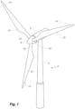
- Fig. 1 illustrates a conventional modern upwind wind turbine according to the so-called "Danish concept" with a tower 4, a nacelle 6 and a rotor with a substantially horizontal rotor shaft.
- the rotor includes a hub 8 and three blades 10 extending radially from the hub 8, each having a blade root 16 nearest the hub and a blade tip 14 farthest from the hub 8.
- the rotor has a radius denoted R.
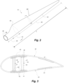
- Fig. 2 shows a schematic view of a wind turbine blade 10.
- the wind turbine blade 10 has the shape of a conventional wind turbine blade and comprises a root region 30 closest to the hub, a profiled or an airfoil region 34 farthest away from the hub and a transition region 32 between the root region 30 and the airfoil region 34.
- the blade 10 comprises a leading edge 18 facing the direction of rotation of the blade 10, when the blade is mounted on the hub, and a trailing edge 20 facing the opposite direction of the leading edge 18.
- the airfoil region 34 (also called the profiled region) has an ideal or almost ideal blade shape with respect to generating lift, whereas the root region 30 due to structural considerations has a substantially circular or elliptical cross-section, which for instance makes it easier and safer to mount the blade 10 to the hub.
- the diameter (or the chord) of the root region 30 may be constant along the entire root area 30.
- the transition region 32 has a transitional profile gradually changing from the circular or elliptical shape of the root region 30 to the airfoil profile of the airfoil region 34.
- the chord length of the transition region 32 typically increases with increasing distance rfrom the hub.
- the airfoil region 34 has an airfoil profile with a chord extending between the leading edge 18 and the trailing edge 20 of the blade 10. The width of the chord decreases with increasing distance rfrom the hub.
- a shoulder 40 of the blade 10 is defined as the position, where the blade 10 has its largest chord length.
- the shoulder 40 is typically provided at the boundary between the transition region 32 and the airfoil region 34.
- Fig. 2 also illustrates the longitudinal extent L, length or longitudinal axis of the blade.
- chords of different sections of the blade normally do not lie in a common plane, since the blade may be twisted and/or curved (i.e. pre-bent), thus providing the chord plane with a correspondingly twisted and/or curved course, this being most often the case in order to compensate for the local velocity of the blade being dependent on the radius from the hub.
- the blade is typically made from a pressure side shell part 36 and a suction side shell part 38 that are glued to each other along bond lines at the leading edge 18 and the trailing edge of the blade 20.
- Fig. 3 shows a schematic view of a cross section of the blade along the line I-I shown in Fig. 2 .
- the blade 10 comprises a pressure side shell part 36 and a suction side shell part 38.
- the pressure side shell part 36 comprises a spar cap 41, also called a main laminate, which constitutes a load bearing part of the pressure side shell part 36.
- the spar cap 41 comprises a plurality of fibre layers 42 mainly comprising unidirectional fibres aligned along the longitudinal direction of the blade in order to provide stiffness to the blade.
- the suction side shell part 38 also comprises a spar cap 45 comprising a plurality of fibre layers 46.
- the pressure side shell part 36 may also comprise a sandwich core material 43 typically made of balsawood or foamed polymer and sandwiched between a number of fibre-reinforced skin layers.
- the sandwich core material 43 is used to provide stiffness to the shell in order to ensure that the shell substantially maintains its aerodynamic profile during rotation of the blade.
- the suction side shell part 38 may also comprise a sandwich core material 47.
- the spar cap 41 of the pressure side shell part 36 and the spar cap 45 of the suction side shell part 38 are connected via a first shear web 50 and a second shear web 55.
- the shear webs 50, 55 are in the shown embodiment shaped as substantially I-shaped webs.
- the first shear web 50 comprises a shear web body and two web foot flanges.
- the shear web body comprises a sandwich core material 51, such as balsawood or foamed polymer, covered by a number of skin layers 52 made of a number of fibre layers.
- the blade shells 36, 38 may comprise further fibre-reinforcement at the leading edge and the trailing edge. Typically, the shell parts 36, 38 are bonded to each other via glue flanges.
- Fig. 4 is a schematic top view of a shell half 38 of a wind turbine blade according to the present invention, illustrating the location of a reinforcing structure 62 having a spanwise extent Se.
- the reinforcing structure 62 comprises three adjacent stacks 66a, 66b, 66c of pultrusion plates.
- the elongate reinforcing structure 62 extends in a substantially spanwise direction of the blade, with adjacent stacks 66a, 66b, 66c of pultrusion plates.
- the elongate reinforcing structure 62 has a tip end 74, closest to the tip end of the blade, and a root end 76, closest to the root end of the blade.
- the elongate reinforcing structure also comprises a spanwise extending front edge 78, which is closest to the leading edge 18 of the blade, and a spanwise extending rear edge 80, which is closest to the trailing edge 20 of the blade.
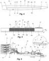
- Fig. 5 is a schematic vertical cross section through part of a shell half with a reinforcing structure 62 of the present invention, as seen from the root end of the blade.
- the reinforcing structure 62 such as a spar cap, comprises a plurality of pultrusion plates 64 according to the present invention, arranged in adjacent stacks 66a-e, which are arranged on blade shell material 89 in mould 77 for the blade shell component, such as a shell half.
- the stacked pultrusion plates 64 are then bonded with the blade shell material 89 to form the blade shell component, such as the shell half with the spar cap.
- Core material 85 is arranged on either chordwise side of the reinforcing structure 62.
- a first shear web 50 and a second shear web 55 is placed on the spar cap 62 via respective bond lines 88.
- the stacks 66a-e may be covered by a carbon biax layer 86 or a carbon veil or a glass/carbon hybrid fabric or a glass/carbon hybrid veil extending towards current connection terminal 87 of a lightning protection system.
- Fig. 6 illustrates a pultrusion process for manufacturing the pultrusion plates 64 of the present invention.
- the pultrusion process makes use of a pultrusion system 90 which comprises a portion for receiving a plurality of bobbins 92 each supplying a tow of glass fibre material 70 and a plurality of bobbins 93 each supply a tow of carbon fibre material 68 from a creel 91. Additional reinforcement material 94 may be provided.
- the tows 68, 70 are pulled through guide plates 95, resin bath 96, and heated die 97 by pulling mechanism 98.
- the pultrusion string 100 is cut into individual pultrusion plates 64 by cutter 99.
- the shaped impregnated fibres are cured and can optionally be wound onto a roll.
- the guide plates and/or the die may take the form of a spreader or inlet comprising multiple apertures, each aperture receiving a respective carbon fibre tow or glass fibre two.
- the apertures can be spaced and they are located so as to guide the fibre tows to form a desired pattern of glass fibre tows and carbon fibre tows in the pultrusion plates 64.
- the enlarged view of the pultrusion plate 64 in Fig. 6 also illustrates its longitudinal axis La and its length I.
- the height/thickness h and width w of the pultrusion plate are illustrated in Fig. 8 , see plate 64f.
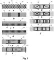
- Fig. 7 is a schematic vertical cross sectional view of different embodiments of the pultrusion plate 64 of the present invention, taken along the line a-a' in Fig. 6 .
- Each pultrusion plate 64 in the various embodiments illustrated in Figs. 7a-j comprises a plurality of tows of glass fibre material 70, indicated as white elliptical shapes, and a plurality of tows of carbon fibre material 68, indicated as black elliptical shapes.
- the tows of glass fibre material 70 and the tows of carbon fibre material 68 are arranged in an array of rows 71 and columns 72 of tows, as seen in a vertical cross section of the pultrusion plate.
- each pultrusion plate comprises a top surface 81, an opposing bottom surface 82 and two lateral surfaces 83, 84, wherein preferably at least one continuous path 67a of adjoining tows of carbon fibre material is provided within the pultrusion plate 64; see Fig. 7f .
- the continuous path 67a of adjoining tows of carbon fibre material extends from the top surface 81 to the opposing bottom surface 82 of the pultrusion plate 64.
- said path of adjoining tows of carbon fibre may be a diagonal path extending from the top surface 81 to the opposing bottom surface 82 of the pultrusion plate.
- a continuous path 67b of adjoining tows of glass fibre material is provided along the lateral edges 83, 84 of the pultrusion plate 64, the continuous path 67b of adjoining tows of glass fibre material extending from the top surface 81 to the opposing bottom surface 82 of the pultrusion plate; as exemplified in Fig. 7f .
- the plurality of tows of glass fibre material 70 and the plurality of tows of carbon fibre material 68 form a non-random pattern, preferably a symmetrical pattern, as seen in a vertical cross section of the pultrusion plate 64.
- Fig. 7a illustrates a checkerboard pattern
- Fig. 7b illustrates a pattern with two vertical lines of tows of carbon fibre material surrounded by tows of glass fibre material
- Figs. 7c and d illustrated various uniform rows of glass fibre tows on top of various uniform rows of carbon fibre tows, and vice versa.
- Fig. 7e illustrates a pattern that comprises two adjacent I-shaped arrangements of tows of carbon fibre material surrounded by tows of glass fibre material
- Fig. 7f-j show different patterns with rectangular arrangements of carbon fibre tows.
- Fig. 8 is a schematic vertical cross sectional view of a reinforcing structure of the present invention, such as a spar cap comprising two chordwise adjacent stacks 66a and 66b of pultrusion plates 64a-f.
- Fig. 8 also illustrates a possible misalignment of the pultrusion plates 64a-f.
- a continuous path 67 of adjoining tows of carbon fibre material 68 extends from the top surface 81 of the uppermost pultrusion plate 64a to the bottom surface 82 of the lowermost pultrusion plate 64c of each stack of pultrusion plates due to the pattern of tows of carbon fibre material and tows of glass fibre material.
Landscapes
- Engineering & Computer Science (AREA)
- Mechanical Engineering (AREA)
- Chemical & Material Sciences (AREA)
- Composite Materials (AREA)
- Moulding By Coating Moulds (AREA)
- Wind Motors (AREA)
Applications Claiming Priority (3)
| Application Number | Priority Date | Filing Date | Title |
|---|---|---|---|
| GBGB2017398.5A GB202017398D0 (en) | 2020-11-03 | 2020-11-03 | Hybrid pultrusion plates for a spar cap of a wind turbine blade |
| PCT/EP2021/080265 WO2022096416A1 (en) | 2020-11-03 | 2021-11-01 | Hybrid pultrusion plates for a spar cap of a wind turbine blade |
| EP21802330.7A EP4240581B1 (de) | 2020-11-03 | 2021-11-01 | Hybride pultrusionsplatten für einen holmgurt einer windturbinenschaufel |
Related Parent Applications (2)
| Application Number | Title | Priority Date | Filing Date |
|---|---|---|---|
| EP21802330.7A Division-Into EP4240581B1 (de) | 2020-11-03 | 2021-11-01 | Hybride pultrusionsplatten für einen holmgurt einer windturbinenschaufel |
| EP21802330.7A Division EP4240581B1 (de) | 2020-11-03 | 2021-11-01 | Hybride pultrusionsplatten für einen holmgurt einer windturbinenschaufel |
Publications (2)
| Publication Number | Publication Date |
|---|---|
| EP4454871A2 true EP4454871A2 (de) | 2024-10-30 |
| EP4454871A3 EP4454871A3 (de) | 2025-01-29 |
Family
ID=73776398
Family Applications (2)
| Application Number | Title | Priority Date | Filing Date |
|---|---|---|---|
| EP24199914.3A Pending EP4454871A3 (de) | 2020-11-03 | 2021-11-01 | Hybride pultrusionsplatten für einen holmgurt einer windturbinenschaufel |
| EP21802330.7A Active EP4240581B1 (de) | 2020-11-03 | 2021-11-01 | Hybride pultrusionsplatten für einen holmgurt einer windturbinenschaufel |
Family Applications After (1)
| Application Number | Title | Priority Date | Filing Date |
|---|---|---|---|
| EP21802330.7A Active EP4240581B1 (de) | 2020-11-03 | 2021-11-01 | Hybride pultrusionsplatten für einen holmgurt einer windturbinenschaufel |
Country Status (8)
| Country | Link |
|---|---|
| US (1) | US20230382062A1 (de) |
| EP (2) | EP4454871A3 (de) |
| CN (2) | CN117644675A (de) |
| CA (1) | CA3193975A1 (de) |
| DK (1) | DK4240581T3 (de) |
| ES (1) | ES3026785T3 (de) |
| GB (1) | GB202017398D0 (de) |
| WO (1) | WO2022096416A1 (de) |
Families Citing this family (3)
| Publication number | Priority date | Publication date | Assignee | Title |
|---|---|---|---|---|
| PL4212324T3 (pl) | 2022-01-17 | 2024-11-25 | Lm Wind Power A/S | Wytwarzanie nakładki na dźwigar łopaty turbiny wiatrowej |
| CN115449183A (zh) * | 2022-08-30 | 2022-12-09 | 明阳智慧能源集团股份公司 | 一种风电叶片导电梁帽制备方法 |
| WO2024240319A1 (en) * | 2023-05-25 | 2024-11-28 | Vestas Wind Systems A/S | A method of manufacturing a plurality of wind turbine blades |
Family Cites Families (33)
| Publication number | Priority date | Publication date | Assignee | Title |
|---|---|---|---|---|
| JPH09322450A (ja) * | 1996-06-04 | 1997-12-12 | Toyota Motor Corp | 電動モータのロータ |
| CN100382950C (zh) * | 2005-01-28 | 2008-04-23 | 赵启林 | 土木工程用混杂纤维拉挤型材加工方法 |
| US20110306718A1 (en) * | 2010-05-11 | 2011-12-15 | Basf Se | Pultrusion process |
| CN102465844A (zh) * | 2010-11-04 | 2012-05-23 | 三一电气有限责任公司 | 一种风力发电机叶片 |
| JP6045566B2 (ja) * | 2011-04-12 | 2016-12-14 | ティコナ・エルエルシー | 繊維ロービングを含浸するためのダイの含浸区分及び方法 |
| DE102012208428A1 (de) * | 2012-05-21 | 2013-11-21 | Evonik Industries Ag | Pul-Core-Verfahren mit PMI-Schaumkern |
| DE102012013448A1 (de) * | 2012-07-05 | 2014-05-08 | Daimler Ag | Faserbündel-Führungseinrichtung zur Anordnung in einer Pultrusionsvorrichtung und Pultrusionsvorrichtung mit einer solchen Faserbündel-Führungseinrichtung |
| CN102817794B (zh) * | 2012-08-24 | 2014-07-23 | 中国人民解放军国防科学技术大学 | 可加长大型复合材料风电叶片 |
| DE102012108132B4 (de) * | 2012-08-31 | 2015-01-22 | Firep Rebar Technology Gmbh | Verfahren zur Herstellung von Bewehrungselementen aus faserverstärktem Kunststoff |
| DK2922690T3 (en) * | 2012-11-20 | 2017-05-22 | Vestas Wind Sys As | Wind turbine blades and methods for making them |
| GB2519566A (en) * | 2013-10-25 | 2015-04-29 | Vestas Wind Sys As | Wind turbine blades |
| DK3062994T3 (da) * | 2013-10-30 | 2021-05-03 | Evonik Operations Gmbh | Kontinuerlig fremstilling af profiler i sandwichkonstruktion med skumkerner og profil fyldt med hårdt skum |
| US9822761B2 (en) * | 2014-08-13 | 2017-11-21 | General Electric Company | Structural components and methods of manufacturing |
| EP3015256A1 (de) * | 2014-10-27 | 2016-05-04 | Evonik Röhm GmbH | Herstellung mehrere unterschiedlicher Faserverbundbauteile für Großserien in einem kontinuierlichen Prozess |
| JP2018501335A (ja) * | 2014-11-20 | 2018-01-18 | ダウ グローバル テクノロジーズ エルエルシー | 促進剤を含む硬化性エポキシ組成物 |
| US20160146184A1 (en) * | 2014-11-25 | 2016-05-26 | General Electric Company | Methods of manufacturing rotor blade components for a wind turbine |
| US20160146185A1 (en) * | 2014-11-25 | 2016-05-26 | General Electric Company | Methods for manufacturing a spar cap for a wind turbine rotor blade |
| NL2013887B1 (nl) * | 2014-11-27 | 2016-09-23 | Fibercore Ip Bv | Werkwijze voor het vormen van een kokervormig halffabricaat uit vezelversterkt kunststofmateriaal. |
| US20160160837A1 (en) * | 2014-12-04 | 2016-06-09 | General Electric Company | Pultruded rotor blade components having interlocking edges |
| WO2016145161A1 (en) * | 2015-03-10 | 2016-09-15 | Zephyros, Inc. | Pultruded articles and methods for making same |
| DE102015206917B4 (de) * | 2015-04-16 | 2022-03-17 | Bayerische Motoren Werke Aktiengesellschaft | Pultrusion von Endlosprofilen mit diskontinuierlichem Querschnittsverlauf |
| US9970304B2 (en) * | 2015-07-22 | 2018-05-15 | General Electric Company | Rotor blade root assembly for a wind turbine |
| US10107257B2 (en) * | 2015-09-23 | 2018-10-23 | General Electric Company | Wind turbine rotor blade components formed from pultruded hybrid-resin fiber-reinforced composites |
| CN105235302B (zh) * | 2015-11-06 | 2018-05-25 | 青岛阿斯顿工程技术转移有限公司 | 一种双稳态融合碳纤维增强复合材料 |
| CA3018577A1 (en) * | 2016-04-20 | 2017-10-26 | Fpinnovations | Methods for producing continuous composite sandwich structures by pultrusion |
| US20180066396A1 (en) * | 2016-09-02 | 2018-03-08 | Precision Fabrics Group, Inc. | Surfacing fabrics, composites comprising the same, and compositions and methods for preparing the same |
| CN107057279B (zh) * | 2016-12-23 | 2019-04-19 | 商丘国龙新材料有限公司 | 一种混杂纤维增强树脂基复合材料及其制备方法 |
| US10987879B2 (en) * | 2017-03-02 | 2021-04-27 | General Electric Company | Methods of manufacturing rotor blade components for a wind turbine |
| US10619622B2 (en) * | 2017-06-21 | 2020-04-14 | General Electric Company | Wind turbine blade with hybrid spar cap and associated method for making |
| US10465653B2 (en) * | 2017-06-21 | 2019-11-05 | General Electric Company | Wind turbine blade with hybrid spar cap and associated method for making |
| US10677216B2 (en) * | 2017-10-24 | 2020-06-09 | General Electric Company | Wind turbine rotor blade components formed using pultruded rods |
| CN110126303A (zh) * | 2019-05-31 | 2019-08-16 | 连云港中复连众复合材料集团有限公司 | 一种用整幅宽拉挤板制备风力发电机组风轮叶片主梁的方法 |
| WO2021213651A1 (en) * | 2020-04-22 | 2021-10-28 | Blade Dynamics Limited | Alternative primer application method |
-
2020
- 2020-11-03 GB GBGB2017398.5A patent/GB202017398D0/en not_active Ceased
-
2021
- 2021-11-01 US US18/030,738 patent/US20230382062A1/en active Pending
- 2021-11-01 WO PCT/EP2021/080265 patent/WO2022096416A1/en not_active Ceased
- 2021-11-01 ES ES21802330T patent/ES3026785T3/es active Active
- 2021-11-01 EP EP24199914.3A patent/EP4454871A3/de active Pending
- 2021-11-01 CN CN202311832480.3A patent/CN117644675A/zh active Pending
- 2021-11-01 EP EP21802330.7A patent/EP4240581B1/de active Active
- 2021-11-01 CA CA3193975A patent/CA3193975A1/en active Pending
- 2021-11-01 CN CN202180055851.4A patent/CN116113539A/zh active Pending
- 2021-11-01 DK DK21802330.7T patent/DK4240581T3/da active
Also Published As
| Publication number | Publication date |
|---|---|
| DK4240581T3 (da) | 2025-03-31 |
| CN117644675A (zh) | 2024-03-05 |
| EP4240581A1 (de) | 2023-09-13 |
| EP4240581B1 (de) | 2025-01-01 |
| GB202017398D0 (en) | 2020-12-16 |
| WO2022096416A1 (en) | 2022-05-12 |
| CA3193975A1 (en) | 2022-05-12 |
| ES3026785T3 (en) | 2025-06-12 |
| US20230382062A1 (en) | 2023-11-30 |
| EP4454871A3 (de) | 2025-01-29 |
| CN116113539A (zh) | 2023-05-12 |
Similar Documents
| Publication | Publication Date | Title |
|---|---|---|
| EP4240581B1 (de) | Hybride pultrusionsplatten für einen holmgurt einer windturbinenschaufel | |
| WO2022129130A1 (en) | Hybrid pultrusion plates for a non-conductive wind turbine blade spar cap | |
| EP4251410B1 (de) | Strömungsverstärkendes gewebe, holmgurt und windturbinenschaufel sowie verfahren zur herstellung eines holmgurts und windturbinenschaufel | |
| US12202214B2 (en) | Interlayer, a spar cap and a wind turbine blade | |
| EP4105007A1 (de) | Verfahren zur herstellung von hybridpultrusionen hoher qualität | |
| US20240068437A1 (en) | Hybrid pultrusion plates for a conductive spar cap of a wind turbine blade | |
| US20240401560A1 (en) | Improved hybrid pultrusion plates for a conductive spar cap of a wind turbine blade | |
| EP4227076A1 (de) | Zweistufige pultrusion zur herstellung von bauteilen einer windturbinenschaufel | |
| EP4305300B1 (de) | Holmkappe für windturbinenrotorblatt mit äquipotentialverbindung | |
| EP4283115A1 (de) | Verbessertes strömungsverstärkendes gewebe, holmkappe und windturbinenschaufel | |
| EP4283116A1 (de) | Windturbinenschaufel mit verbessertem blitzschutzsystem | |
| US12071925B2 (en) | Wind turbine blade with reinforcing structure | |
| EP4335629A1 (de) | Vorgehärtete faserelemente für eine holmkappe einer windturbinenschaufel |
Legal Events
| Date | Code | Title | Description |
|---|---|---|---|
| PUAI | Public reference made under article 153(3) epc to a published international application that has entered the european phase |
Free format text: ORIGINAL CODE: 0009012 |
|
| STAA | Information on the status of an ep patent application or granted ep patent |
Free format text: STATUS: THE APPLICATION HAS BEEN PUBLISHED |
|
| AC | Divisional application: reference to earlier application |
Ref document number: 4240581 Country of ref document: EP Kind code of ref document: P |
|
| AK | Designated contracting states |
Kind code of ref document: A2 Designated state(s): AL AT BE BG CH CY CZ DE DK EE ES FI FR GB GR HR HU IE IS IT LI LT LU LV MC MK MT NL NO PL PT RO RS SE SI SK SM TR |
|
| REG | Reference to a national code |
Ref country code: DE Ref legal event code: R079 Free format text: PREVIOUS MAIN CLASS: B29C0070880000 Ipc: B29D0099000000 |
|
| PUAL | Search report despatched |
Free format text: ORIGINAL CODE: 0009013 |
|
| AK | Designated contracting states |
Kind code of ref document: A3 Designated state(s): AL AT BE BG CH CY CZ DE DK EE ES FI FR GB GR HR HU IE IS IT LI LT LU LV MC MK MT NL NO PL PT RO RS SE SI SK SM TR |
|
| RIC1 | Information provided on ipc code assigned before grant |
Ipc: B29C 70/88 20060101ALI20241220BHEP Ipc: B29C 70/52 20060101ALI20241220BHEP Ipc: B29D 99/00 20100101AFI20241220BHEP |
|
| STAA | Information on the status of an ep patent application or granted ep patent |
Free format text: STATUS: REQUEST FOR EXAMINATION WAS MADE |
|
| 17P | Request for examination filed |
Effective date: 20250703 |
|
| GRAP | Despatch of communication of intention to grant a patent |
Free format text: ORIGINAL CODE: EPIDOSNIGR1 |
|
| STAA | Information on the status of an ep patent application or granted ep patent |
Free format text: STATUS: GRANT OF PATENT IS INTENDED |
|
| RIC1 | Information provided on ipc code assigned before grant |
Ipc: B29D 99/00 20100101AFI20250919BHEP Ipc: B29C 70/52 20060101ALI20250919BHEP Ipc: B29C 70/88 20060101ALI20250919BHEP |
|
| GRAJ | Information related to disapproval of communication of intention to grant by the applicant or resumption of examination proceedings by the epo deleted |
Free format text: ORIGINAL CODE: EPIDOSDIGR1 |
|
| STAA | Information on the status of an ep patent application or granted ep patent |
Free format text: STATUS: REQUEST FOR EXAMINATION WAS MADE |
|
| INTG | Intention to grant announced |
Effective date: 20251021 |