EP4454812A1 - Substrate processing method and substrate processing device - Google Patents
Substrate processing method and substrate processing device Download PDFInfo
- Publication number
- EP4454812A1 EP4454812A1 EP22910568.9A EP22910568A EP4454812A1 EP 4454812 A1 EP4454812 A1 EP 4454812A1 EP 22910568 A EP22910568 A EP 22910568A EP 4454812 A1 EP4454812 A1 EP 4454812A1
- Authority
- EP
- European Patent Office
- Prior art keywords
- substrate
- shaft
- notch
- distance sensor
- movable shaft
- Prior art date
- Legal status (The legal status is an assumption and is not a legal conclusion. Google has not performed a legal analysis and makes no representation as to the accuracy of the status listed.)
- Pending
Links
Images




Classifications
-
- B—PERFORMING OPERATIONS; TRANSPORTING
- B24—GRINDING; POLISHING
- B24B—MACHINES, DEVICES, OR PROCESSES FOR GRINDING OR POLISHING; DRESSING OR CONDITIONING OF ABRADING SURFACES; FEEDING OF GRINDING, POLISHING, OR LAPPING AGENTS
- B24B49/00—Measuring or gauging equipment for controlling the feed movement of the grinding tool or work; Arrangements of indicating or measuring equipment, e.g. for indicating the start of the grinding operation
- B24B49/006—Measuring or gauging equipment for controlling the feed movement of the grinding tool or work; Arrangements of indicating or measuring equipment, e.g. for indicating the start of the grinding operation taking regard of the speed
-
- B—PERFORMING OPERATIONS; TRANSPORTING
- B24—GRINDING; POLISHING
- B24B—MACHINES, DEVICES, OR PROCESSES FOR GRINDING OR POLISHING; DRESSING OR CONDITIONING OF ABRADING SURFACES; FEEDING OF GRINDING, POLISHING, OR LAPPING AGENTS
- B24B27/00—Other grinding machines or devices
- B24B27/033—Other grinding machines or devices for grinding a surface for cleaning purposes, e.g. for descaling or for grinding off flaws in the surface
-
- B—PERFORMING OPERATIONS; TRANSPORTING
- B24—GRINDING; POLISHING
- B24B—MACHINES, DEVICES, OR PROCESSES FOR GRINDING OR POLISHING; DRESSING OR CONDITIONING OF ABRADING SURFACES; FEEDING OF GRINDING, POLISHING, OR LAPPING AGENTS
- B24B41/00—Component parts such as frames, beds, carriages, headstocks
- B24B41/06—Work supports, e.g. adjustable steadies
- B24B41/067—Work supports, e.g. adjustable steadies radially supporting workpieces
-
- B—PERFORMING OPERATIONS; TRANSPORTING
- B24—GRINDING; POLISHING
- B24B—MACHINES, DEVICES, OR PROCESSES FOR GRINDING OR POLISHING; DRESSING OR CONDITIONING OF ABRADING SURFACES; FEEDING OF GRINDING, POLISHING, OR LAPPING AGENTS
- B24B41/00—Component parts such as frames, beds, carriages, headstocks
- B24B41/06—Work supports, e.g. adjustable steadies
- B24B41/068—Table-like supports for panels, sheets or the like
-
- B—PERFORMING OPERATIONS; TRANSPORTING
- B24—GRINDING; POLISHING
- B24B—MACHINES, DEVICES, OR PROCESSES FOR GRINDING OR POLISHING; DRESSING OR CONDITIONING OF ABRADING SURFACES; FEEDING OF GRINDING, POLISHING, OR LAPPING AGENTS
- B24B49/00—Measuring or gauging equipment for controlling the feed movement of the grinding tool or work; Arrangements of indicating or measuring equipment, e.g. for indicating the start of the grinding operation
- B24B49/10—Measuring or gauging equipment for controlling the feed movement of the grinding tool or work; Arrangements of indicating or measuring equipment, e.g. for indicating the start of the grinding operation involving electrical means
-
- B—PERFORMING OPERATIONS; TRANSPORTING
- B24—GRINDING; POLISHING
- B24B—MACHINES, DEVICES, OR PROCESSES FOR GRINDING OR POLISHING; DRESSING OR CONDITIONING OF ABRADING SURFACES; FEEDING OF GRINDING, POLISHING, OR LAPPING AGENTS
- B24B49/00—Measuring or gauging equipment for controlling the feed movement of the grinding tool or work; Arrangements of indicating or measuring equipment, e.g. for indicating the start of the grinding operation
- B24B49/12—Measuring or gauging equipment for controlling the feed movement of the grinding tool or work; Arrangements of indicating or measuring equipment, e.g. for indicating the start of the grinding operation involving optical means
-
- B—PERFORMING OPERATIONS; TRANSPORTING
- B24—GRINDING; POLISHING
- B24B—MACHINES, DEVICES, OR PROCESSES FOR GRINDING OR POLISHING; DRESSING OR CONDITIONING OF ABRADING SURFACES; FEEDING OF GRINDING, POLISHING, OR LAPPING AGENTS
- B24B7/00—Machines or devices designed for grinding plane surfaces on work, including polishing plane glass surfaces; Accessories therefor
- B24B7/04—Machines or devices designed for grinding plane surfaces on work, including polishing plane glass surfaces; Accessories therefor involving a rotary work-table
-
- B—PERFORMING OPERATIONS; TRANSPORTING
- B24—GRINDING; POLISHING
- B24B—MACHINES, DEVICES, OR PROCESSES FOR GRINDING OR POLISHING; DRESSING OR CONDITIONING OF ABRADING SURFACES; FEEDING OF GRINDING, POLISHING, OR LAPPING AGENTS
- B24B7/00—Machines or devices designed for grinding plane surfaces on work, including polishing plane glass surfaces; Accessories therefor
- B24B7/20—Machines or devices designed for grinding plane surfaces on work, including polishing plane glass surfaces; Accessories therefor characterised by a special design with respect to properties of the material of non-metallic articles to be ground
- B24B7/22—Machines or devices designed for grinding plane surfaces on work, including polishing plane glass surfaces; Accessories therefor characterised by a special design with respect to properties of the material of non-metallic articles to be ground for grinding inorganic material, e.g. stone, ceramics, porcelain
- B24B7/228—Machines or devices designed for grinding plane surfaces on work, including polishing plane glass surfaces; Accessories therefor characterised by a special design with respect to properties of the material of non-metallic articles to be ground for grinding inorganic material, e.g. stone, ceramics, porcelain for grinding thin, brittle parts, e.g. semiconductors, wafers
-
- H—ELECTRICITY
- H10—SEMICONDUCTOR DEVICES; ELECTRIC SOLID-STATE DEVICES NOT OTHERWISE PROVIDED FOR
- H10P—GENERIC PROCESSES OR APPARATUS FOR THE MANUFACTURE OR TREATMENT OF DEVICES COVERED BY CLASS H10
- H10P52/00—Grinding, lapping or polishing of wafers, substrates or parts of devices
-
- H—ELECTRICITY
- H10—SEMICONDUCTOR DEVICES; ELECTRIC SOLID-STATE DEVICES NOT OTHERWISE PROVIDED FOR
- H10P—GENERIC PROCESSES OR APPARATUS FOR THE MANUFACTURE OR TREATMENT OF DEVICES COVERED BY CLASS H10
- H10P70/00—Cleaning of wafers, substrates or parts of devices
- H10P70/60—Cleaning only by mechanical processes
-
- H—ELECTRICITY
- H10—SEMICONDUCTOR DEVICES; ELECTRIC SOLID-STATE DEVICES NOT OTHERWISE PROVIDED FOR
- H10P—GENERIC PROCESSES OR APPARATUS FOR THE MANUFACTURE OR TREATMENT OF DEVICES COVERED BY CLASS H10
- H10P72/00—Handling or holding of wafers, substrates or devices during manufacture or treatment thereof
- H10P72/04—Apparatus for manufacture or treatment
- H10P72/0402—Apparatus for fluid treatment
- H10P72/0406—Apparatus for fluid treatment for cleaning followed by drying, rinsing, stripping, blasting or the like
- H10P72/0411—Apparatus for fluid treatment for cleaning followed by drying, rinsing, stripping, blasting or the like for wet cleaning or washing
- H10P72/0412—Apparatus for fluid treatment for cleaning followed by drying, rinsing, stripping, blasting or the like for wet cleaning or washing using mainly scrubbing means, e.g. brushes
-
- H—ELECTRICITY
- H10—SEMICONDUCTOR DEVICES; ELECTRIC SOLID-STATE DEVICES NOT OTHERWISE PROVIDED FOR
- H10P—GENERIC PROCESSES OR APPARATUS FOR THE MANUFACTURE OR TREATMENT OF DEVICES COVERED BY CLASS H10
- H10P72/00—Handling or holding of wafers, substrates or devices during manufacture or treatment thereof
- H10P72/04—Apparatus for manufacture or treatment
- H10P72/0451—Apparatus for manufacturing or treating in a plurality of work-stations
- H10P72/0468—Apparatus for manufacturing or treating in a plurality of work-stations comprising a chamber adapted to a particular process
- H10P72/0472—Apparatus for manufacturing or treating in a plurality of work-stations comprising a chamber adapted to a particular process comprising at least one polishing chamber
-
- H—ELECTRICITY
- H10—SEMICONDUCTOR DEVICES; ELECTRIC SOLID-STATE DEVICES NOT OTHERWISE PROVIDED FOR
- H10P—GENERIC PROCESSES OR APPARATUS FOR THE MANUFACTURE OR TREATMENT OF DEVICES COVERED BY CLASS H10
- H10P72/00—Handling or holding of wafers, substrates or devices during manufacture or treatment thereof
- H10P72/06—Apparatus for monitoring, sorting, marking, testing or measuring
- H10P72/0604—Process monitoring, e.g. flow or thickness monitoring
-
- H—ELECTRICITY
- H10—SEMICONDUCTOR DEVICES; ELECTRIC SOLID-STATE DEVICES NOT OTHERWISE PROVIDED FOR
- H10P—GENERIC PROCESSES OR APPARATUS FOR THE MANUFACTURE OR TREATMENT OF DEVICES COVERED BY CLASS H10
- H10P72/00—Handling or holding of wafers, substrates or devices during manufacture or treatment thereof
- H10P72/06—Apparatus for monitoring, sorting, marking, testing or measuring
- H10P72/0606—Position monitoring, e.g. misposition detection or presence detection
-
- H—ELECTRICITY
- H10—SEMICONDUCTOR DEVICES; ELECTRIC SOLID-STATE DEVICES NOT OTHERWISE PROVIDED FOR
- H10P—GENERIC PROCESSES OR APPARATUS FOR THE MANUFACTURE OR TREATMENT OF DEVICES COVERED BY CLASS H10
- H10P72/00—Handling or holding of wafers, substrates or devices during manufacture or treatment thereof
- H10P72/70—Handling or holding of wafers, substrates or devices during manufacture or treatment thereof for supporting or gripping
- H10P72/76—Handling or holding of wafers, substrates or devices during manufacture or treatment thereof for supporting or gripping using mechanical means, e.g. clamps or pinches
- H10P72/7604—Handling or holding of wafers, substrates or devices during manufacture or treatment thereof for supporting or gripping using mechanical means, e.g. clamps or pinches the wafers being placed on a susceptor, stage or support
- H10P72/7608—Handling or holding of wafers, substrates or devices during manufacture or treatment thereof for supporting or gripping using mechanical means, e.g. clamps or pinches the wafers being placed on a susceptor, stage or support characterised by a plurality of separate clamping members, e.g. clamping fingers
-
- H—ELECTRICITY
- H10—SEMICONDUCTOR DEVICES; ELECTRIC SOLID-STATE DEVICES NOT OTHERWISE PROVIDED FOR
- H10P—GENERIC PROCESSES OR APPARATUS FOR THE MANUFACTURE OR TREATMENT OF DEVICES COVERED BY CLASS H10
- H10P90/00—Preparation of wafers not covered by a single main group of this subclass, e.g. wafer reinforcement
- H10P90/12—Preparing bulk and homogeneous wafers
- H10P90/123—Preparing bulk and homogeneous wafers by grinding or lapping
-
- B—PERFORMING OPERATIONS; TRANSPORTING
- B24—GRINDING; POLISHING
- B24B—MACHINES, DEVICES, OR PROCESSES FOR GRINDING OR POLISHING; DRESSING OR CONDITIONING OF ABRADING SURFACES; FEEDING OF GRINDING, POLISHING, OR LAPPING AGENTS
- B24B41/00—Component parts such as frames, beds, carriages, headstocks
- B24B41/007—Weight compensation; Temperature compensation; Vibration damping
-
- B—PERFORMING OPERATIONS; TRANSPORTING
- B24—GRINDING; POLISHING
- B24B—MACHINES, DEVICES, OR PROCESSES FOR GRINDING OR POLISHING; DRESSING OR CONDITIONING OF ABRADING SURFACES; FEEDING OF GRINDING, POLISHING, OR LAPPING AGENTS
- B24B51/00—Arrangements for automatic control of a series of individual steps in grinding a workpiece
Definitions
- the present invention relates to a substrate processing method and a substrate processing apparatus for processing a substrate, such as a wafer.
- CMOS sensors Devices, such as memory circuits, logic circuits, and image sensors (e.g., CMOS sensors), are becoming more highly integrated these days.
- foreign matters e.g., fine particles and dust
- Foreign matters adhering to a device can cause a short-circuit between interconnects or a circuit defect. Therefore, in order to enhance reliability of devices, it is necessary to clean a substrate (e.g., wafer), on which devices are formed, by bringing a processing tool (e.g., cleaning tool) into contact with the substrate to thereby remove foreign matter on the substrate.
- a processing tool e.g., cleaning tool
- the above-described foreign matters may adhere also to a back surface (bare-silicon surface) of the substrate. If such foreign matters adhere to the back surface of the substrate, the substrate may separate from a stage reference surface, or a front surface of the substrate may be inclined with respect to the stage reference surface in an exposure apparatus, resulting in patterning shift or deviation of focal distance. To prevent such problems, it is necessary to remove the foreign matters by bringing a processing tool (e.g., polishing tool) into contact with the back surface of the substrate to thereby remove foreign matter on the substrate.
- a processing tool e.g., polishing tool
- a substrate holding apparatus in which a periphery of a substrate is held by rollers coupled to eccentric shafts, and the substrate is rotated about its own axis while the substrate is made a circular motion by rotating the eccentric shafts about their axes, with positions of the eccentric shafts themselves remain stationary (for example, see Japanese Laid-Open Patent Publication No. 2019-83224 ).
- a processing tool can process the entirety of the surface, including its outermost area, of the substrate while preventing the rollers from coming into contact with the processing tool.
- the combination of the circular motion of the substrate and the rotation of the substrate about its axis can increase speed of the substrate at any point on the surface of the substrate. As a result, an efficiency of processing of the substrate can be improved.
- Patent document 1 Japanese laid-open patent publication No. 2021-2639
- the substrate When the substrate is rotated around its own axis by the rollers coupled to the eccentric shafts while the substrate is made a circular motion, it is possible to indirectly determine a rotational speed of the substrate based on a ratio of a diameter of the substrate to a diameter of the roller and a rotational speed of the rollers. On the other hand, it is difficult to directly measure the rotational speed of the substrate. Accordingly, in a conventional substrate processing apparatus, the theoretical rotation speed of the substrate is matched to the set rotation speed by controlling the rotation speed of the rollers.
- an actual rotational speed of the substrate may deviate from the theoretical rotational speed.
- causes of deviation of the actual rotation speed from the theoretical rotation speed include: (1) manufacturing and/or processing errors between each roller (e.g., errors in the diameter of the substrate contact surface between each roller), (2) errors in the diameter between each substrate (or the circumference between each substrate), (3) slipping of the substrate on the substrate contact surface of the roller caused due to a decrease in gripping force of the roller on the substrate, (4) slipping of the substrate on the substrate contact surface of the roller caused due to a magnitude of frictional force between the processing tool and the surface of the substrate, and (5) wear in the substrate contact surface of the roller (i.e., change in a diameter of the roller).
- a substrate processing method comprising: contacting a periphery of a substrate having a notch with three or more rollers each secured to three or more eccentric shafts including at least one reference shaft and at least one movable shaft which can be moved in a direction closer to and away from the reference shaft, each of the eccentric shafts having a first shaft portion coupled to electric motor, and a second shaft portion which is eccentric from the first shaft portion and to which the rollers are secured; rotating the first shaft portions of the three or more eccentric shafts about their respective own axes, and further causes the three or more rollers to make a circular motion, thereby rotating the substrate about its axis and causing the substrate to make a circular motion; contacting a processing tool with the rotating and circularly moving substrate to thereby process the substrate; calculating a rotational speed of the substrate, during processing of the substrate, based on measured values of a notch detection sensor for detecting that a notch has passed through the movable shaft; and issuing an alarm when the calculated rotational
- the substrate processing method further comprises: performing an additional processing to the substrate based on a difference or a ratio between the rotational speed of the substrate and the theoretical rotational speed when the calculated rotational speed of the substrate falls below a lower limit of the allowable range.
- the notch detection sensor is an acceleration sensor configured to measure acceleration generated when the movable shaft moves closer to and away from the reference shaft.
- the notch detection sensor is a distance sensor configured to measure a movement distance of the movable shaft when the movable shaft moves closer to and away from the reference shaft.
- a substrate processing method comprising: contacting a periphery of a substrate having a notch with three or more rollers each secured to three or more eccentric shafts including at least one reference shaft and at least one movable shaft which can be moved in a direction closer to and away from the reference shaft, each of the eccentric shafts having a first shaft portion coupled to electric motors, and a second shaft portion which is eccentric from the first shaft portion and to which the rollers are secured; rotating the first shaft portions of the three or more eccentric shafts about their respective own axes, and further causes the three or more rollers to make a circular motion, thereby rotating the substrate about its axis and causing the substrate to make a circular motion; contacting a processing tool with the rotating and circularly moving substrate to thereby process the substrate; measuring, during processing of the substrate, a movement distance of the movable shaft by use of a distance sensor, and further detecting that a notch has passed through the movable shaft, by use of a notch detection sensor; is
- the alarm is canceled even if the measured value of the distance sensor is out of the predetermined allowable range.
- a substrate processing method comprising: contacting a periphery of a substrate having a notch with three or more rollers each secured to three or more eccentric shafts including at least one reference shaft and at least one movable shaft which can be moved in a direction closer to and away from the reference shaft, each of the eccentric shafts having a first shaft portion coupled to electric motors, and a second shaft portion which is eccentric from the first shaft portion and to which the rollers are secured; rotating the first shaft portions of the three or more eccentric shafts about their respective own axes, and further causes the three or more rollers to make a circular motion, thereby rotating the substrate about its axis and causing the substrate to make a circular motion; contacting a processing tool with the rotating and circularly moving substrate to thereby process the substrate; measuring, during processing of the substrate, a movement distance of the movable shaft by use of a distance sensor, and further detecting that a notch has passed through the movable shaft, by use of the distance sensor; issuing an alarm
- the alarm is canceled even if the measured value of the distance sensor is out of the predetermined allowable range.
- a substrate processing apparatus comprising: three or more eccentric shafts including at least one reference shaft and at least one movable shaft, each of the eccentric shafts having a first shaft portion, and a second shaft portion which is eccentric from the first shaft portion; three or more rollers each secured to the second shaft portion of each of the three or more eccentric shafts, and capable of contacting a periphery of a substrate having a notch; three or more electric motors for rotating the first shaft portions of the three or more eccentric shafts about their respective own axes, and further causes the three or more rollers to make a circular motion, thereby rotating the substrate about its axis and causing the substrate to make a circular motion; an actuator configured to move the at least one movable shaft in a direction closer to and away from the reference shaft; a processing tool configured to contact a surface of the rotating and circularly moving substrate to thereby process the surface of the substrate; a notch detection sensor configured to detect that the notch has passed through the movable shaft; and a controller
- the controller is configured to perform an additional processing to the substrate based on a difference or a ratio between the rotational speed of the substrate and the theoretical rotational speed when the calculated rotational speed of the substrate falls below a lower limit of the allowable range.
- the notch detection sensor is an acceleration sensor configured to measure acceleration generated when the movable shaft moves closer to and away from the reference shaft.
- the notch detection sensor is a distance sensor configured to measure a movement distance of the movable shaft when the movable shaft moves closer to and away from the reference shaft.
- a substrate processing apparatus comprising: three or more eccentric shafts including at least one reference shaft and at least one movable shaft, each of the eccentric shafts having a first shaft portion, and a second shaft portion which is eccentric from the first shaft portion; three or more rollers each secured to the second shaft portion of each of the three or more eccentric shafts, and capable of contacting a periphery of a substrate having a notch; three or more electric motors for rotating the first shaft portions of the three or more eccentric shafts about their respective own axes, and further causes the three or more rollers to make a circular motion, thereby rotating the substrate about its axis and causing the substrate to make a circular motion; an actuator configured to move the at least one movable shaft in a direction closer to and away from the reference shaft; a processing tool configured to contact a surface of the rotating and circularly moving substrate to thereby process the surface of the substrate; a notch detection sensor configured to detect that the notch has passed through the movable shaft; a distance sensor
- the controller is configured to cancel the alarm, during a predetermined rotation angle of the roller before and after a time point of detection of the notch by the notch detection sensor, even if the measured value of the distance sensor is out of the predetermined allowable range.
- a substrate processing apparatus comprising: three or more eccentric shafts including at least one reference shaft and at least one movable shaft, each of the eccentric shafts having a first shaft portion, and a second shaft portion which is eccentric from the first shaft portion; three or more rollers each secured to the second shaft portion of each of the three or more eccentric shafts, and capable of contacting a periphery of a substrate having a notch; three or more electric motors for rotating the first shaft portions of the three or more eccentric shafts about their respective own axes, and further causes the three or more rollers to make a circular motion, thereby rotating the substrate about its axis and causing the substrate to make a circular motion; an actuator configured to move the at least one movable shaft in a direction closer to and away from the reference shaft; a processing tool configured to contact a surface of the rotating and circularly moving substrate to thereby process the surface of the substrate; a distance sensor configured to measure a movement distance of the movable shaft when the movable shaft moves closer to
- the controller is configured to cancel the alarm, during a predetermined rotation angle of the roller before and after a time point of detection of the notch by the distance sensor, even if the measured value of the distance sensor is out of the predetermined allowable range.
- the notch detection sensor or the distance sensor monitors whether or not the substrate is rotating properly, and thus an alarm is issued when there is an abnormality in the rotation of the wafer W.
- the substrate can be processed while monitoring whether or not the substrate is properly held by the rollers.
- FIG. 1 is a plan view schematically showing a substrate processing apparatus according to one embodiment
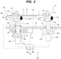
- FIG. 2 is a side view showing the substrate processing apparatus shown in FIG. 1
- FIG. 3 is a bottom view showing the substrate processing apparatus shown in FIG. 1 .
- a processing tool shown in FIG. 1 is not illustrated.
- the substrate processing apparatus 100 shown in FIGS. 1 through 3 has a substrate holding apparatus 10 configured to cause a wafer W, which is an example of a substrate, to make a circular motion and rotate the wafer W about its axis, while holding the wafer W.
- the substrate holding apparatus 10 includes a plurality of rollers 11a and a plurality of rollers 11b, both of which are capable of contacting a periphery of the wafer W, a plurality of electric motors 29a and a plurality of electric motors 29b for rotating the rollers 11a, 11b, respectively, a plurality of eccentric shafts 13a and a plurality of eccentric shafts 13b coupling the rollers 11a, 11b and the electric motors 29a, 29b to each other, respectively, and a controller 40 for causing the electric motors 29a, 29b to rotate at the same speed with the same phase.
- the controller 40 includes at least one computer.
- the controller 40 includes a memory 40a and an arithmetic device 40b.
- the arithmetic device 40b includes a CPU (Central Processing Unit) or a GPU (Graphic Processing Unit) that performs arithmetic operations according to instructions contained in a program stored in the memory 40a.
- the memory 40a includes a main memory (for example, a random access memory) that can be accessed by the arithmetic device 40b, and an auxiliary memory (for example, a hard disk drive or a solid state drive) that stores data and the program.
- Each roller 11a has a wafer holding surface (or a substrate holding surface) 31a for holding the periphery of the wafer W
- each roller 11b has a wafer holding surface (or a substrate holding surface) 31b for holding the periphery of the wafer W.
- Each roller 11a and each roller 11b have the same structure and the same size.
- the eccentric shafts 13a, 13b are arranged around a predetermined central axis CP of the substrate holding apparatus 10.
- the substrate holding apparatus 10 in this embodiment includes two rollers 11a, two rollers 11b, two eccentric shafts 13a, two eccentric shafts 13b, two electric motors 29a, and two electric motors 29b. It is noted, however, that the number of each of these components is not limited to those of this embodiment.
- Each of the eccentric shafts 13a has a first shaft portion 14a, a second shaft portion 15a which is eccentric relative to the first shaft portion 14a, and an intermediate shaft portion 16a that couples the first shaft portion 14a to the second shaft portion 15a.
- At least two of the first shaft portion 14a, the second shaft portion 15a, and the intermediate shaft portion 16a may be an integrated structure.
- the first shaft portion 14a and the intermediate shaft portion 16a may be an integrated structure.
- all of the first shaft portion 14a, the second shaft portion 15a, and the intermediate shaft portion 16a in its entirety may be an integrated structure.
- Each of the eccentric shafts 13a shown in FIG. 2 has a shape of a crankshaft, but the shape of each of the eccentric shafts 13a is not limited to this embodiment as long as the second shaft portion 15a is eccentric by a predetermined distance from the first shaft portion 14a.
- the rollers 11a are secured to ends of the second shaft portions 15a, respectively, and the other ends of the second shaft portions 15a are secured to the intermediate shaft portions 16a, respectively.
- Ends of the first shaft portions 14a are coupled to the electric motors 29a through couplings 28a, respectively, and the other ends of the first shaft portions 14a are secured to the intermediate shaft portions 16a, respectively.
- Each of the eccentric shafts 13b has a first shaft portion 14b, a second shaft portion 15b which is eccentric relative to the first shaft portion 14b, and an intermediate shaft portion 16b that couples the first shaft portion 14b to the second shaft portion 15b. At least two of the first shaft portion 14b, the second shaft portion 15b, and the intermediate shaft portion 16b may be an integrated structure. For example, the first shaft portion 14b and the intermediate shaft portion 16b may be an integrated structure. In another example, all of the first shaft portion 14b, the second shaft portion 15b, and the intermediate shaft portion 16b in its entirety may be an integrated structure.
- Each of the eccentric shafts 13b shown in FIG. 2 has a shape of a crankshaft, but the shape of each of the eccentric shafts 13b is not limited to this embodiment as long as the second shaft portion 15b is eccentric by a predetermined distance from the first shaft portion 14b.
- the rollers 11b are secured to ends of the second shaft portions 15b, respectively, and the other ends of the second shaft portions 15b are secured to the intermediate shaft portions 16b, respectively.
- Ends of the first shaft portions 14b are coupled to the electric motors 29b through couplings 28b, respectively, and the other ends of the first shaft portions 14b are secured to the intermediate shaft portions 16b, respectively.
- Each electric motor 29a is configured to rotate the eccentric shaft 13a about the first shaft portion 14a
- each electric motor 29b is configured to rotate the eccentric shaft 13b about the first shaft portion 14b.
- the electric motors 29a, 29b are coupled to the controller 40.
- each eccentric shaft 13a is eccentric by a distance e from the first shaft portion 14a. Accordingly, when the electric motor 29a is set in motion, the roller 11a, while rotating about the second shaft portion 15a, makes a circular motion with a radius e. An axis of the roller 11a coincides with an axis of the second shaft portion 15a. Therefore, the roller 11a, while rotating about its axis, makes a circular motion with the radius e around the axis of the first shaft portion 14a.
- each eccentric shaft 13b is eccentric by a distance e from the first shaft portion 14b. Accordingly, when the electric motor 29b is set in motion, the roller 11b, while rotating about the second shaft portion 15b, makes a circular motion with a radius e. An axis of the roller 11b coincides with an axis of the second shaft portion 15b. Therefore, the roller 11b, while rotating about its axis, makes a circular motion with the radius e around the axis of the first shaft portion 14b.
- the circular motion is defined as a movement of an object in a circular orbit.
- the controller 40 is configured to cause all the electric motors 29a, 29b to rotate at the same speed with the same phase. More specifically, the controller 40 instructs the electric motors 29a, 29b such that all the electric motors 29a, 29b start at the same timing and all the electric motors 29a, 29b rotate in the same direction. Further, the controller 40 synchronizes the respective rotational speeds and the respective phases of the electric motors 29a, 29b during the operations of the electric motors 29a, 29b.
- the substrate holding apparatus 10 can rotate the wafer W about its axis while causing the wafer W to make a circular motion.
- the combination of the circular motion of the wafer W and the rotation of the wafer W about its axis can increase speed of the wafer W at any point on the surface of the wafer W. Therefore, when a processing head 200, which will be described later, is pressed against the surface of the wafer W, a relative speed between the processing head 200 and the surface of the wafer W can be increased, thereby increasing a processing rate of the wafer W.
- a counter weight 17a and a counter weight 17b are secured to each eccentric shaft 13a and each eccentric shaft 13b, respectively. More specifically, the counter weights 17a, 17b are secured to the intermediate shaft portions 16a, 16b, respectively.
- the counter weight 17a and the roller 11a are arranged symmetrically with respect to the first shaft portion 14a.
- the counter weight 17a has a weight set such that a centrifugal force, which is generated in the radial direction from the first shaft portion 14a toward the roller 11a when the eccentric shaft 13a is rotating about the first shaft portion 14a, is canceled by a centrifugal force generated in the counter weight 17a.
- the counter weight 17b and the roller 11b are arranged symmetrically with respect to the first shaft portion 14b.
- the counter weight 17b has a weight set such that a centrifugal force, which is generated in the radial direction from the first shaft portion 14b toward the roller 11b when the eccentric shaft 13b is rotating about the first shaft portion 14b, is canceled by a centrifugal force generated in the counter weight 17b.
- Such counter weights 17a, 17b can prevent vibration of the eccentric shafts 13a, 13b due to weight imbalance during rotation of the eccentric shafts 13a, 13b.
- the substrate holding apparatus 10 further includes a base plate 20, a plurality of linear motion guides 26 secured to a lower surface of the base plate 20, a plurality of movable bases 21 supported by the linear motion guides 26, and a plurality of actuators 18 coupled to the movable bases 21.
- Each linear motion guide 26 is configured to restrict movement of each movable base 21 to a linear movement in a direction parallel to the lower surface of the base plate 20.
- Each movable base 21 has a bearing 24 which rotatably supports the eccentric shaft 13b, and a coupling member 23 coupled to each actuator 18.
- the actuators 18 are coupled to the eccentric shafts 13b through the movable bases 21, respectively.
- the movable bases 21, which include the bearings 24, respectively, are independently moved together with the eccentric shafts 13b by the actuators 18, respectively.
- the actuators 18 are secured to the lower surface of the base plate 20.
- the operations of the actuators 18 are controlled by the controller 40.
- the controller 40 is configured to be able to operate the actuators 18 independently of each other.
- Each actuator 18 is configured to move each movable base 21 in parallel with the base plate 20.
- the eccentric shafts 13a extend through the base plate 20.
- the rollers 11a are arranged above the base plate 20, while the electric motors 29a are arranged below the base plate 20.
- the eccentric shafts 13a are rotatably supported by bearings 19 held on the base plate 20. Positions of these eccentric shafts 13a are fixed.
- the electric motors 29a are secured to the base plate 20 through electric motor support members 27a, respectively. More specifically, the electric motor support members 27a are secured to the lower surface of the base plate 20, and the electric motors 29a are secured to the electric motor support members 27a, respectively.
- the eccentric shafts 13b extend through the movable bases 21 and the base plate 20.
- the rollers 11b are arranged above the base plate 20, while the electric motors 29b are arranged below the base plate 20.
- the eccentric shafts 13b are rotatably supported by the bearings 24 of the movable bases 21, respectively.
- the electric motors 29b are secured to the movable bases 21 through electric motor support members 27b, respectively. More specifically, the electric motor support members 27b are secured to the lower surface of the movable bases 21, and the electric motors 29b are secured to the electric motor support members 27b, respectively.
- the eccentric shafts 13a are reference shafts that cannot move relative to the base plate 20, while the eccentric shafts 13b are movable shafts that can move relative to the base plate 20.
- the eccentric shafts 13a may be referred to as reference shafts 13a
- the eccentric shafts 13b may be referred to as movable shafts 13b.
- the actuators 18 are coupled to the movable shafts 13b through the movable bases 21.
- Each movable base 21 has the bearing 24 which rotatably supports the movable shaft 13b, and the coupling member 23 coupled to the actuator 18. Therefore, the movable base 21 couples the actuator 18 to the movable shaft 13b.
- the actuators 18 can move the movable shafts 13b through the movable bases 21 in parallel with the base plate 20. Specifically, the actuators 18 are configured to move the movable shafts 13b in a direction closer to the reference shafts 13a and in a direction away from the reference shafts 13a. When the two movable shafts 13b move in the direction closer to the reference shafts 13a, the wafer W is held by the two rollers 11a and the two rollers 11b. When the two movable shafts 13b move in the direction away from the two reference shafts 13a, the wafer W is released from the two rollers 11a and the two rollers 11b.
- the actuators 18 and the linear motion guides 26 are oriented toward the central axis CP of the substrate holding apparatus 10.
- the actuators 18 move the movable shafts 13b in directions of arrows illustrated in FIG. 3 .
- the direction closer to the reference shafts 13a and the direction away from the reference shafts 13a corresponds to a direction toward the central axis CP and a direction away from the central axis CP.
- the rollers 11b can hold the wafer W with clamping forces acting toward the center of the wafer W.
- the substrate holding apparatus 10 can efficiently hold the wafer W with a minimum force.
- each of the actuators 18 and each of the linear motion guides 26 may be oriented toward each of the reference shafts 13a.
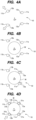
- FIGS. 4A through 4D are schematic views each illustrating operations of the substrate holding apparatus 10 when receiving the wafer W.
- each actuator 18 see FIGS. 2 and 3 .
- each roller 11b is operated to move each roller 11b in the direction away from the central axis CP.
- the rollers 11a and the rollers 11b are eccentric outwardly.
- the wafer W is transported to the substrate holding apparatus 10 by a not-shown transport device.
- the reference shafts 13a are rotated 180 degrees to move the rollers 11a inwardly.
- the actuators 18 are actuated to move the rollers 11b and the movable shafts 13b in the direction closer to the reference shafts 13a until the rollers 11b come into contact with the wafer W.
- the periphery of the wafer W is held by the wafer holding surfaces 31a of the rollers 11a and the wafer holding surfaces 31b of the rollers 11b.
- the steps shown in FIGS. 4A through 4D are performed in the reverse order.
- the two movable shafts 13b are supported by the two movable bases 21, respectively, and further coupled to the two actuators 18, respectively. Accordingly, even when vibration occurs in one movable shaft 13b during rotation of the wafer W, the above discussed configurations can prevent the vibration from propagating to the other movable shaft 13b. As a result, the substrate holding apparatus 10 can stably hold the wafer W.
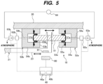
- FIG. 5 is a schematic view showing the actuator 18 according to an embodiment.
- Each actuator 18 includes a piston 51 arranged in a longitudinal direction of the actuator 18, housings 52a, 52b arranged outwardly of the piston 51, and separation membranes (i.e., diaphragms) 55a, 55b which form pressure chambers 57a, 57b between the piston 51 and the housings 52a, 52b.
- the piston 51 is configured to be movable in directions indicated by arrows in FIG. 5 (i.e., in the longitudinal direction of the actuator 18).
- the housings 52a, 52b are arranged away from the piston 51.
- the housing 52a is arranged so as to surround one end of the piston 51, and the housing 52b is arranged so as to surround the other end of the piston 51.
- the coupling member 23 of the movable base 21 is coupled to the piston 51, and thus the piston 51 is supported by the coupling member 23.
- the movable base 21, including the coupling member 23, is configured to be movable together with the piston 51 in directions indicated by arrows in FIG. 5 . More specifically, the movable base 21 is configured to be movable together with the piston 51 in the direction closer to the reference shaft 13a and in the direction away from the reference shaft 13a.
- the actuator 18 is oriented toward the central axis CP of the substrate holding apparatus 10 (see FIG. 3 )
- the moving directions of the piston 51 and the movable base 21 correspond to the direction toward the central axis CP and the direction away from the central axis CP.
- the housings 52a, 52b include, respectively, housing bodies 53a, 53b, each which is arranged so as to surround a side surface of the piston 51, and lids 54a, 54b, each which is fixed to the housing bodies 53a, 53b.
- a rim of the diaphragm 55a is sandwiched between the housing body 53a and the lid 54a.
- a rim of the diaphragm 55b is sandwiched between the housing body 53b and the lid 54b.
- the pressure chamber 57a is formed by the diaphragm 55a and an inner surface of the housing 52a.
- the pressure chamber 57b is formed by the diaphragm 55b and an inner surface of the housing 52b. More specifically, the pressure chamber 57a is formed by the diaphragm 55a and an inner surface of the lid 54a, and the pressure chamber 57b is formed by the diaphragm 55b and an inner surface of the lid 54b.
- the diaphragms 55a, 55b have the same structure. In this embodiment, the housings 52a, 52b have the same structure, but may have different structures to each other.
- Compressed-gas flow passages 59a, 59b are formed in the lids 54a, 54b of the housings 52a, 52b, respectively.
- the compressed-gas flow passages 59a, 59b are coupled to a compressed-gas supply source 64 via pressure regulators 62a, 62b and switching valves 63a, 63b.
- the pressure chambers 57a, 57b communicate with the pressure regulators 62a, 62b through the compressed-gas flow passages 59a, 59b, respectively.
- the switching valves 63a, 63b are operated to allow the pressure chambers 57a, 57b to communicate with the compressed-gas supply source 64.
- the switching valves 63a, 63b are coupled to the controller 40.
- the switching valves 63a, 63b are valves for allowing the pressure chambers 57a, 57b to communicate with the compressed-gas supply source 64 or the atmosphere selectively. Three-way valves may be used as the switching valves 63a, 63b.
- a compressed gas such as compressed air
- the compressed-gas supply source 64 may include a pump, and a compressed-gas supply line which has been pre-installed as a utility in a factory.
- Pressures of the compressed gas in the pressure chambers 57a, 57b are regulated by the pressure regulators 62a, 62b, respectively.
- the pressure regulators 62a, 62b are electro-pneumatic regulators.
- the pressure regulators 62a, 62b in this embodiment are coupled to the controller 40.
- the pressure regulators 62a, 62b may be manually operated pressure regulators. In this case, the pressure regulators 62a, 62b are not coupled to the controller 40.
- the controller 40 transmits predetermined set pressure values to the pressure regulators 62a, 62b, respectively.
- the pressure regulators 62a, 62b are configured to regulate the pressures of the compressed gas in the pressure chambers 57a, 57b according to the set pressure values. Examples of such pressure regulators 62a, 62b may include electro-pneumatic regulators, and mechanical regulators. In one embodiment, the pressure regulator 62b may be an electro-pneumatic regulator, while the pressure regulator 62a may be a mechanical regulator. In the case where the pressure regulator 62a is the mechanical regulator, the pressure regulator 62a is not coupled to the controller 40.
- the piston 51 moves in response to a difference between the pressure in the pressure chamber 57a and the pressure in the pressure chamber 57b.
- the piston 51 is moved in the direction away from the reference shaft 13a (see FIG. 3 ).
- the piston 51 is moved in the direction closer to the reference shaft 13a (see FIG. 3 ).
- the compressed gas when the piston 51 is to be moved, the compressed gas is introduced into both the pressure chambers 57a, 57b such that the pressure of the compressed gas in one of the pressure chambers 57a, 57b is higher than the pressure of the compressed gas in the other.
- the compressed gas when the piston 51 is to be moved, the compressed gas may be introduced into only one of the pressure chamber 57a and the pressure chamber 57b, and the other may communicate with the atmosphere.
- FIG. 6 is a cross-sectional view schematically showing the diaphragms 55a, 55b according to an embodiment.
- the diaphragm 55a has a central portion 71a in contact with one end of the piston 51, an inner wall portion 72a connected to the central portion 71a and extending along the side surface of the piston 51, a folded-back portion 73a connected to the inner wall portion 72a and having a curved cross section, and an outer wall portion 74a connected to the folded-back portion 73a and located outside the inner wall portion 72a.
- the diaphragm 55a is in contact with one end of the piston 51.
- the outer wall portion 74a contacts the inner surface of the housing body 53a.
- the central portion 71a has a circular shape.
- the inner wall portion 72a and the outer wall portion 74a each have a cylindrical shape, and the inner wall portion 72a is in contact with the side surface of the piston 51.
- the outer wall portion 74a is arranged so as to surround the inner wall portion 72a.
- the diaphragm 55b has a central portion 71b in contact with the other end of the piston 51, an inner wall portion 72b connected to the central portion 71b and extending along the side surface of the piston 51, a folded-back portion 73b connected to the inner wall portion 72b and having a curved cross section, and an outer wall portion 74b connected to the folded-back portion 73b and located outside the inner wall portion 72b.
- the diaphragm 55b is in contact with the other end of the piston 51.
- the outer wall portion 74b contacts the inner surface of the housing body 53b.
- the central portion 71b has a circular shape.
- the inner wall portion 72b and the outer wall portion 74b each have a cylindrical shape, and the inner wall portion 72b is in contact with the side surface of the piston 51.
- the outer wall portion 74b is arranged so as to surround the inner wall portion 72b.
- the diaphragms 55a, 55b are in contact with the piston 51, but are not fixed to the piston 51.
- a thick portion 75a, constituting the rim of the diaphragm 55a is sandwiched between the housing body 53a and the lid 54a.
- a thick portion 75b, constituting the rim of the diaphragm 55b is sandwiched between the housing body 53b and the lid 54b.
- the diaphragms 55a, 55b are made of flexible material. Examples of material constructing the diaphragms 55a, 55b may include chloroprene rubber, fluoro-rubber, and silicone rubber. Chloroprene rubber having a high resistance to flex fatigue is preferably used.
- FIG. 7A is a view showing a state of the actuator 18 when the pressure in the pressure chamber 57a (first pressure chamber 57a) is higher than the pressure in the pressure chamber 57b (second pressure chamber 57b).
- FIG. 7B is a view showing a state of the actuator 18 when the pressure in the pressure chamber 57b is higher than the pressure in the pressure chamber 57a.
- Such motions of the diaphragms 55a, 55b enable the piston 51 to move smoothly while the piston 51 hardly receives a reaction force from the diaphragms 55a, 55b.
- a piston and a housing are in contact with each other as in a typical air cylinder, a sliding resistance is generated between the piston and the housing when vibration occurs during rotation of a wafer. Such sliding resistance exerts an excessive load on a rotating wafer, thus causing unstable holding of the wafer.
- the housings 52a, 52b are arranged away from the piston 51, no sliding resistance is generated between the piston 51 and the housings 52a, 52b. As a result, the substrate holding apparatus 10 can stably hold the wafer W without exerting an excessive load on the wafer W.
- the substrate holding apparatus 10 includes the two reference shafts 13a, the two movable shafts 13b, the two actuators 18, the two movable bases 21, and the two linear motion guides 26 arranged around the central axis CP, while the number and interval of arrangements of these components are not limited to this embodiment.
- the substrate holding apparatus 10 may include one movable shaft 13b and two or more reference shafts 13a arranged around the central axis CP at appropriate intervals.
- the substrate holding apparatus 10 includes one actuator 18, one movable base 21, and one linear motion guide 26.
- the substrate holding apparatus 10 may include three or more movable shafts 13b, and three or more reference shafts 13a arranged around the central axis CP at appropriate intervals.
- the substrate holding apparatus 10 includes three or more actuators 18, three or more movable bases 21, and three or more linear motion guides 26.
- the substrate processing apparatus 100 further includes a processing head 200 for bringing a processing tool 201 into contact with a first surface 1 of the wafer W, held by the substrate holding apparatus 10, to thereby process the first surface 1.
- the processing head 200 is located below the wafer W held by the substrate holding apparatus 10, and a position of the processing head 200 is fixed.
- the first surface 1 of the wafer W is a back surface of the wafer W, i.e. a non-device surface, where no device is formed or no device is to be formed.
- a second surface 2 of the wafer W, which is opposite from the first surface 1, is a front surface, i.e. a device surface, where a device(s) is formed or a device(s) is to be formed.
- the wafer W, with its first surface 1 facing downward, is horizontally held by the substrate holding apparatus 10.
- the substrate holding apparatus 10 brings the plurality of rollers 11a and the plurality of rollers 11b into contact with the periphery of the wafer W, and rotates the rollers 11a, 11b about their respective own axes, and further causes the rollers 11a, 11b to make a circular motion, thereby rotating the wafer W, which is held by the rollers 11a, 11b, about its axis and causing the wafer W to make a circular motion.
- the processing head 200 places the processing tool 201 in contact with the first surface 1 of the wafer W to thereby process the first surface 1.
- the processing tool 201 is longer than a radius of the wafer W.
- One end of the processing tool 201 protrudes outwardly from the periphery of the wafer W, while the other end of the processing tool 201 extends across the central axis CP of the substrate holding apparatus 10. Accordingly, the processing head 200 can bring the processing tool 201 into contact with the entirety of the first surface 1 of the rotating wafer W. As a result, this configuration enables the processing tool 201 to process the entirety of the first surface 1, including the outermost area, of the wafer W.
- the processing head 200 is located in such a position as not to contact the rollers 11a, 11b and the eccentric shafts 13a, 13b when the wafer W is making a circular motion.
- the substrate holding apparatus 10 can rotate the wafer W about its axis while allowing the wafer W to make a circular motion.
- the combination of the circular motion of the wafer W and the rotation of the wafer W about its axis can increase the speed of the wafer W at any point on the surface of the wafer W. Therefore, the relative speed between the processing tool 201 and the surface of the wafer W can be increased, thereby increasing a processing rate of the wafer W.
- the processing tool 201 may be a polishing tool for polishing the first surface 1 of the wafer W.
- the polishing tool may include a polishing tape, and a grindstone.
- the processing tool 201 may be a cleaning tool for cleaning the first surface 1 of the wafer W.
- a cleaning tape is an example of the cleaning tool.
- a tape made of nonwoven fabric is an example of the cleaning tape.
- the substrate processing apparatus 100 may include the processing head 200 that processes the second surface 2 of the wafer W by bringing the processing tool 201 into contact with the second surface 2 of the wafer W held by the substrate holding device 10.
- the processing tool 201 may be a cleaning tool for cleaning the second surface 2 of the wafer W.
- the processing head 200 is located above the wafer W held by the substrate holding device 10.
- the substrate holding device 10 of the substrate processing apparatus 100 has a notch detection sensor 77.
- the notch detection sensor 77 is mounted to one of the movable shafts 13b.
- the notch detection sensor 77 may be mounted to any of the movable base 21, the electric motor support member 27b, the coupling 28b, and the electric motor 29b.
- the notch detection sensor 77 is a sensor capable of detecting whether or not a notch Nw (see FIG. 1 ) of the wafer W passes through the movable shaft 13b to which the notch detection sensor 77 is mounted.
- the notch detection sensor 77 is coupled to the controller 40, and transmits measured values thereof to the controller 40.
- an acceleration sensor is used as the notch detection sensor 77.
- a vibration sensor may be used as the notch detection sensor 77.
- the movable shaft 13b moves closer to and away from the reference shaft 13a according to the shape of the notch Nw (in the example shown in FIG. 1 , a shape of circular arc). As a result, relatively large acceleration or vibration is generated in the movable shaft 13b.
- FIG. 8 is a graph showing an example of the measured values of the notch detection sensor.
- a vertical axis represents an acceleration of the movable shaft 13b, to which the notch detection sensor 77 is mounted, in the horizontal direction
- a horizontal axis represents a rotation angle of the first shaft portion 14b in the movable shaft 13b to which the notch detection sensor 77 is mounted.
- a characteristic plurality of waveforms Pk1 having a large peak, respectively, correspond to waveforms that represent passage of the notch Nw of the wafer W through the movable shaft 13b.
- the waveform Pk1 may be referred to as "passing waveform Pk1".
- the wafer W held by the plurality of rollers 11a, 11b makes one rotation.
- the roller 11b rotates multiple times during the adjacent passing waveforms Pk1.
- the controller 40 can create the graph shown in FIG. 8 from the measured values of the notch detection sensor 77.
- the controller 40 monitors whether or not the wafer W is rotating at a desired rotational speed (or a set rotational speed) based on the measured values received from the notch detection sensor 77. For example, the controller 40 calculates the rotational speed of the wafer W based on the measured values received from the notch detection sensor 77, and compares the calculated rotational speed of the wafer W with an allowable range that has been determined with respect to a theoretical rotational speed of the wafer W, thereby determining whether or not the wafer W is rotating at the desired rotational speed.
- the theoretical rotational speed of the wafer W can be calculated from a diameter of the wafer W, diameters of the rollers 11a, 11b, and rotational speeds of the electric motors 29a, 29b.
- the theoretical rotational speed of the wafer W may be calculated from a ratio of the diameter of the wafer W to the diameters of the rollers 11a, 11b, and the rotational speeds of the electric motors 29a, 29b.
- the controller 40 stores in advance this theoretical rotational speed and the allowable range determined with respect to the theoretical rotational speed.
- the controller 40 can calculate the rotational speed of the wafer W from the number of passing waveforms Pk1 counted during a predetermined time interval (e.g., 10 seconds).
- a predetermined time interval e.g. 10 seconds.
- time between adjacent passing waveforms Pk1 i.e., time during one rotation of the wafer W
- the rotational speed of the wafer W can be calculated based on this counted time.
- the controller 40 is configured to compare the rotational speed of the wafer W, which is calculated based on the measured values of the notch detection sensor 77, with the allowable range, and to issue an alarm when the rotational speed of the wafer W is out of the allowable range.
- the alarm enables operator for the substrate processing apparatus to realize that an abnormal rotation of the wafer W has occurred, and as a result, to check whether or not a processing abnormality has occurred on the wafer W.
- the controller 40 may issue an alarm and further stop the processing operation of the wafer W.
- the controller 40 may store a signal to identify the wafer W that was being processed when the alarm was issued, in association with the wafer W, and continue the processing operation of the wafer W.
- Examples of causing the rotational speed of the wafer W calculated based on the measured values of the notch detection sensor 77 to exceed an upper limit of the allowable range may include a defect in the wafer W, a defect in the rollers 1 1a, 11b, and an abnormal rotation of the electric motors 29a, 29b.
- the alarm enables operator to quickly check status of the wafer W, the rollers 11a, 11b, and the electric motors 29a, 29b, and perform, if necessary, maintenance and/or replacement of the rollers 11a, 11b and the electric motors 29a, 29b.
- Examples of causing the rotational speed of the wafer W calculated based on the measured values of the notch detection sensor 77 to fall below a lower limit of the allowable range include wear of the rollers 11a, 11b, and occurrence of slipping between the rollers 11a, 11b and the wafer W. In this case, there is a concern that processing performance in the substrate processing apparatus may be reduced (e.g., polishing performance may be reduced or cleaning performance may be reduced).
- the alarm enables operator to identify the wafer W on which the abnormal rotation of wafer W has occurred and to check whether that wafer W has any processing abnormality.
- the controller 40 may perform additional processing to the wafer W based on a difference or a ratio between the rotational speed of the wafer W calculated based on the measured values of the notch detection sensor 77 and the theoretical rotational speed of the wafer W. For example, if the rotational speed of wafer W calculated based on the measured values of the notch detection sensor 77 is 10% lower than the theoretical rotational speed, the controller 40 may increase processing time by 10%.
- a relational equation or a data table between the ratio of the actual rotational speed to the theoretical rotational speed and the increased amount of processing time may be obtained in advance through experiments that have been carried out previously, and this relational equation or this data table may be stored in advance in the controller 40.
- the controller 40 calculates the ratio of the rotational speed of the wafer W calculated based on the measured values of the notch detection sensor 77 to the theoretical rotational speed, and calculates the increased amount of processing time from this ratio and the relational equation or the data table.
- the controller 40 calculates the rotational speed of the wafer W based on the measured values received from the notch detection sensor 77.
- the rotational speed of the wafer W monitored by the controller 40 includes also a value corresponding to the rotational speed of the wafer W calculated based on the measured values of the notch detection sensor 77.
- the controller 40 may monitor the number of passing waveforms Pk1 counted during a predetermined time interval (e.g., 10 seconds). In this case, the controller 40 stores in advance the theoretical number of passing waveforms Pk1 calculated from the theoretical rotational speed of the wafer W and an allowable range that is determined with respect to the theoretical number of passing waveforms Pk1.
- the controller 40 compares the counted number of passing waveforms Pk1 with the allowable range, and issues an alarm when the counted number of passing waveforms Pk1 is out of the allowable range. As described above, the controller 40 may issue an alarm, and further stop the processing operation of the wafer W in the substrate processing apparatus, or may store a signal to identify the wafer W that was processed when the alarm was issued, in association with the wafer W, and continue the processing operation of the wafer W in the substrate processing apparatus.
- the substrate holding device 10 may have a noncontact type distance sensor 80 for measuring a movement distance of the movable shaft 13b, instead of the notch detection sensor 77 shown in FIG. 2 .
- the distance sensor 80 serves as a sensor capable of detecting the position of the movable shaft 13a relative to the reference shaft 13a, and further is used as the notch detection sensor capable of detecting that the notch Nw (see FIG. 1 ) of the wafer W has passed.
- Configurations of this embodiment which will not be particularly described, are the same as those of the substrate processing apparatus 100 having the notch detection sensor 77 shown in FIG. 2 , and redundant descriptions thereof will be omitted.
- the distance sensor 80 is arranged outside the actuator 18, and is located near the actuator 18 and the movable base 21.
- a magnet 81 is secured to the coupling member 23 of the movable base 21, and the distance sensor 80 faces the magnet 81.
- the distance sensor 80 is a magnetic sensor, and can measure a distance of the movement of the magnet 81 relative to the distance sensor 80.
- a position of the distance sensor 80 is fixed.
- the movable base 21, the piston 51, and the movable shaft 13b can move in unison. Therefore, when the movable shaft 13b moves in the direction closer to the reference shaft 13a and in the direction away from the reference shaft 13a, a relative position of the magnet 81 secured to the movable base 21 with respect to the distance sensor 80 is changed.
- a movement distance of the magnet 81 corresponds to the movement distance of the movable shaft 13b. Therefore, the distance sensor 80 can measure the movement distance of the movable shaft 13b.
- the movement distance of the movable shaft 13b means a position of the movable shaft 13b relative to a predetermined reference position.
- the position of the movable shaft 13b relative to the predetermined reference position may be simply referred to a position of the movable shaft 13b.
- the distance sensor 80 is coupled to the controller 40, and transmits a measured value of the movement distance of the movable shaft 13b to the controller 40.
- the movable shaft 13b moves closer to and away from the reference shaft 13a according to the shape of the notch Nw (in the example shown in FIG. 1 , a shape of circular arc).
- the distance sensor 80 can detect that the notch Nw has passed through the movable shaft 13b.
- FIG. 9 is a graph showing an example of the measured values of the distance sensor shown in FIG. 5 .
- a vertical axis represents a movement distance of the movable shaft 13b, to which the notch detection sensor 77 is mounted
- a horizontal axis represents a rotation angle of the first shaft portion 14b in the movable shaft 13b.
- a characteristic plurality of waveforms Pk2 having a large peak, respectively, correspond to waveforms that represent passage of the notch Nw of the wafer W through the movable shaft 13b.
- the waveform Pk2 may be referred to as "passing waveform Pk2".
- the wafer W held by the plurality of rollers 11a, 11b makes one rotation.
- the roller 11b rotates multiple times during the adjacent passing waveforms Pk2.
- the measured values of the distance sensor 80 plot an approximate sinusoidal wave during one rotation of the roller 11b.
- the controller 40 can create the graph shown in FIG. 9 from the measured values of the distance sensor 80.
- the controller 40 calculates the rotational speed of the wafer W from the number of passing waveforms Pk2 counted during a predetermined time interval (e.g., 10 seconds), or time between adjacent passing waveforms Pk2 (i.e., time during one rotation of the wafer W), and monitors whether or not the wafer W is rotating at a desired rotational speed (or a set rotational speed). Further, the controller 40 compares the rotational speed of the wafer W, which is calculated based on the measured values of the distance sensor 80, with an allowable range that has been determined with respect to a theoretical rotational speed of the wafer W, thereby determining whether or not the wafer W is rotating at the desired rotational speed.
- a predetermined time interval e.g. 10 seconds
- time between adjacent passing waveforms Pk2 i.e., time during one rotation of the wafer W
- the controller 40 compares the rotational speed of the wafer W, which is calculated based on the measured values of the distance sensor 80, with an allowable range
- the controller 40 is configured to issue an alarm when the rotational speed of the wafer W, which is calculated based on the measured values of the distance sensor 80, is out of the allowable range.
- the controller 40 may issue the alarm and further stop the processing operation of the wafer W, or may store a signal to identify the wafer W that was being processed when the alarm was issued, in association with the wafer W, and may continue the processing operation of the wafer W.
- the controller 40 may perform an additional processing on the wafer W based on the difference or the ratio between the rotational speed of the wafer W, calculated based on the measured values of distance sensor 80, and the theoretical rotational speed of the wafer W. Furthermore, the controller 40 may use the number of passing waveforms Pk2 counted during the predetermined time interval (e.g., 10 seconds) as a monitoring target.
- the predetermined time interval e.g. 10 seconds
- the distance sensor 80 may be a noncontact type optical sensor.
- the distance sensor 80 shown in FIG. 10 includes a sensor head 84 having a light-emitting element and a light-receiving element (both not shown) provided at a front end thereof, a converging lens 85 for converging light emitted from the sensor head 84, an amplifier 93 coupled to the sensor head 84 by a light-emitting optical fiber cable 92A and a light-receiving optical fiber cable 92B, and a distance calculator 94 electrically connected to the amplifier 93.
- the converging lens 85 is mounted to the front end of the sensor head 84.
- the sensor head 84 is secured to an outside of the actuator 18, and the front end of the sensor head 84 is oriented toward the movable base 21. More specifically, in this embodiment, a sensor target 88 is mounted to the movable base 21, and the front end of the sensor head 84 is oriented toward the sensor target 88.
- the sensor target 88 has a property of reflecting light.
- An example of the sensor target 88 may include a member composed of ceramic or metal.
- the amplifier 93 and the distance calculator 94 are located away from the actuator 18.
- the amplifier 93 has a light source 93a for emitting light, and a light-intensity measuring device 93b for measuring intensity of reflected light.
- the light emitted from the light source 93a of the amplifier 93 is transmitted through the light-emitting optical fiber cable 92A to the sensor head 84.
- the sensor head 84 directs the light to the sensor target 88 through the converging lens 85, and receives the reflected light from the sensor target 88.
- the reflected light is transmitted through the light-receiving optical fiber cable 92B to the amplifier 93.
- the light-intensity measuring device 93b of the amplifier 93 measures the intensity of the reflected light.
- the amplifier 93 sends the measured value of intensity of the reflected light to the distance calculator 94, and the distance calculator 94 converts the measured value of the intensity of the reflected light into a distance.
- the distance obtained by the distance calculator 94 corresponds to the movement distance of the movable shaft 13b.
- the distance calculator 94 may be built-in to the controller 40.
- the controller 40 may have a function of the distance calculator 94.
- the controller 40 may also serve as the distance calculator.
- the amplifier 93 directly sends the measured value of intensity of the reflected light to the controller 40, and the distance is calculated in the controller 40.
- the distance sensor 80 in this embodiment can measure the movement distance of the movable shaft 13b.
- the distance calculator 94 is coupled to the controller 40, and the distance calculator 94 transmits the measured value of movement distance of the movable shaft 13b to the controller 40.
- the distance sensor 80 may not include the converging lens 85.
- the sensor head 84 may direct the light to the sensor target 88 without passing through the converging lens 85, and may receive the reflected light from the sensor target 88 without passing through the converging lens 85.
- the sensor head 84 which is one of components constituting the distance sensor 80, is mounted to the actuator 18.
- the sensor head 84 has a function to only emit light and receive reflected light, and therefore the sensor head 84 per se is very compact.
- the substrate holding device 10 of the substrate processing apparatus 100 has the notch detection sensor 77 shown in FIG. 2 , and the distance sensor 80 shown in FIG. 5 or FIG. 10 .
- the distance sensor 80 serves as a sensor to determine whether or not the rollers 11a, 11b of the substrate holding device 10 are holding the wafer W properly.
- the distance sensor 80 is coupled to the controller 40, and the distance sensor 80 sends the measured value of movement distance of the movable shaft 13b (i.e., the measured value of position of the movable shaft 13b) to the controller 40.
- the controller 40 can compare the measured value of movement distance of the movable shaft 13b (i.e., the position of the movable shaft 13b) with the preset allowable range to thereby determine whether or not the substrate holding device 10 is properly holding the wafer W (i.e., whether or not the substrate holding device 10 has any abnormality).
- the controller 40 is configured to issue an alarm signal when the measured value of the movement distance described above is out of the allowable range.
- the controller 40 can detect the vibration of the movable shaft 13b based on the fluctuation of the position of the movable shaft 13b (or the fluctuation of the measured value of movement distance of the movable shaft 13b) during the rotation of the wafer W.
- the controller 40 can detect abnormal rotation of the wafer W based on the vibration of the movable shaft 13b when the substrate holding apparatus 10 holds and rotates the wafer W. Possible causes of the abnormal rotation of the wafer W include wear, deformation, breakage, and dimensional defect of the wafer holding surfaces 31a, 31b of the rollers 11a, 11b, and phase shift of the rotations of the rollers 11a, 11b.
- FIG. 11A is a view showing an example of the measured values of the distance sensor
- FIG. 11B is a view showing an example of the measured values of the notch detection sensor 77.
- a vertical axis represents the position of the movable shaft 13B to which the notch detection sensor 77 is mounted
- a horizontal axis represents an angle of rotation of the roller 11B secured to one end of the movable shaft 13B.
- a vertical axis represents an acceleration of the movable shaft 13b, to which the notch detection sensor 77 is mounted, in the horizontal direction
- a horizontal axis represents an angle of rotation of the roller 11b secured to one end of the movable shaft 13B.
- a value indicating the position of the movable shaft 13b decreases as the movable shaft 13b moves closer to the reference shaft 13a, and increases as the movable shaft 13b moves away from the reference shaft 13a.
- a position 0 of the movable shaft 13b is defined as a position where the movable shaft 13b is closest to the reference shaft 13a within the movable range of the actuator 18.
- a rotation angle of 0 degrees of the roller 11b is defined as a predetermined reference angle of the roller 11b.
- a curve illustrated by a dotted line represents measured values of the distance sensor 80 when an abnormal rotation of the wafer W is occurring. As shown in FIG.
- the controller 40 compares the amplitude of position of the movable shaft 13b (the measured value of movement distance of the movable shaft 13b) with the predetermined allowable range, and determines that the abnormal rotation of the wafer W has occurred when the amplitude of position of the movable shaft 13b is out of the allowable range.
- the amplitude of position of the movable shaft 13b is defined as a width of the vibration of the movable shaft 13b.
- the amplitude of the movable shaft 13b corresponds to a difference between a maximum value and a minimum value of positions of the movable shaft 13b during one or more rotations of the roller 11b.
- the controller 40 is configured not to issue an alarm when the measured value of the distance sensor 80 is out of the predetermined allowable range and the distance sensor 80 detects the notch Nw.
- the controller 40 utilizes the passing waveform Pk1 in the measured values of the notch detection sensor 77.
- the controller 40 is configured to cancel the alarm, during a predetermined rotation angle (RA) of the roller 11b before and after a time point of detection of the notch Nw from the notch detection sensor 77 (i.e., before and after the passing waveform Pk1), even if the measured value of the distance sensor 80 is out of the predetermined allowable range.
- the predetermined rotation angle (RA) can be set freely. Such a configuration prevents the passing waveform Pk2, measured when the notch passes the movable shaft 13b, from being determined as the abnormal rotation of the wafer W.
- the notch detection sensor 77 may be omitted.
- the distance sensor 80 serves as both a sensor capable of detecting that the notch Nw of the wafer W has passed through the movable shaft 13b, and a sensor for determining whether or not the rollers 11a, 11b of the substrate holding device 10 are holding the wafer W properly.
- the controller 40 is configured to cancel the alarm, during the predetermined rotation angle (RB) of the roller 11b before and after the time point of detection of the notch Nw from the distance sensor 80 (i.e., before and after the passing waveform Pk2), even if the measured values of the distance sensor 80 is out of the predetermined allowable range. More specifically, when a peak that is out of the allowable range (hereinafter referred to as a deviation peak) is detected, the controller 40 determines whether or not other peaks that is out of the allowable range are detected in a range of the predetermined rotation angle (RB) before and after the deviation peak.
- a peak that is out of the allowable range hereinafter referred to as a deviation peak
- the controller 40 determines that the deviation peak is the passing waveform Pk2, and thus does not issue (or cancels) the alarm. If other peak that is out of the allowable range is detected in the range of the predetermined rotation angle (RB), the controller 40 determines that the rotation abnormality of the wafer W is occurring, and thus issues the alarm.
- the predetermined rotation angle (RB) can be set freely.
- the predetermined rotation angle (RB) can be set between rotations R2 and R3 before and after the one rotation R1 of the roller that has caused the passing waveform Pk2. Such a configuration prevents the passing waveform Pk2, measured when the notch passes through the movable shaft 13b, from being determined as the abnormal rotation of the wafer W.
- the present invention is applicable to a substrate processing method and a substrate processing apparatus for processing a substrate, such as a wafer.
Landscapes
- Engineering & Computer Science (AREA)
- Mechanical Engineering (AREA)
- Chemical & Material Sciences (AREA)
- Ceramic Engineering (AREA)
- Inorganic Chemistry (AREA)
- Container, Conveyance, Adherence, Positioning, Of Wafer (AREA)
- Constituent Portions Of Griding Lathes, Driving, Sensing And Control (AREA)
- Grinding Of Cylindrical And Plane Surfaces (AREA)
- Mechanical Treatment Of Semiconductor (AREA)
- Cleaning Or Drying Semiconductors (AREA)
Abstract
Description
- The present invention relates to a substrate processing method and a substrate processing apparatus for processing a substrate, such as a wafer.
- Devices, such as memory circuits, logic circuits, and image sensors (e.g., CMOS sensors), are becoming more highly integrated these days. In a process for forming such a device, foreign matters (e.g., fine particles and dust) may adhere to the device. Foreign matters adhering to a device can cause a short-circuit between interconnects or a circuit defect. Therefore, in order to enhance reliability of devices, it is necessary to clean a substrate (e.g., wafer), on which devices are formed, by bringing a processing tool (e.g., cleaning tool) into contact with the substrate to thereby remove foreign matter on the substrate.
- The above-described foreign matters, such as fine particles and dust, may adhere also to a back surface (bare-silicon surface) of the substrate. If such foreign matters adhere to the back surface of the substrate, the substrate may separate from a stage reference surface, or a front surface of the substrate may be inclined with respect to the stage reference surface in an exposure apparatus, resulting in patterning shift or deviation of focal distance. To prevent such problems, it is necessary to remove the foreign matters by bringing a processing tool (e.g., polishing tool) into contact with the back surface of the substrate to thereby remove foreign matter on the substrate.
- There has recently been an increasing demand for an apparatus which can more efficiently process an entirety of a substrate surface. Therefore, a substrate holding apparatus has been proposed in which a periphery of a substrate is held by rollers coupled to eccentric shafts, and the substrate is rotated about its own axis while the substrate is made a circular motion by rotating the eccentric shafts about their axes, with positions of the eccentric shafts themselves remain stationary (for example, see
Japanese Laid-Open Patent Publication No. 2019-83224 - Patent document 1:
Japanese laid-open patent publication No. 2021-2639 - When the substrate is rotated around its own axis by the rollers coupled to the eccentric shafts while the substrate is made a circular motion, it is possible to indirectly determine a rotational speed of the substrate based on a ratio of a diameter of the substrate to a diameter of the roller and a rotational speed of the rollers. On the other hand, it is difficult to directly measure the rotational speed of the substrate. Accordingly, in a conventional substrate processing apparatus, the theoretical rotation speed of the substrate is matched to the set rotation speed by controlling the rotation speed of the rollers.
- However, an actual rotational speed of the substrate may deviate from the theoretical rotational speed. Examples of causes of deviation of the actual rotation speed from the theoretical rotation speed include: (1) manufacturing and/or processing errors between each roller (e.g., errors in the diameter of the substrate contact surface between each roller), (2) errors in the diameter between each substrate (or the circumference between each substrate), (3) slipping of the substrate on the substrate contact surface of the roller caused due to a decrease in gripping force of the roller on the substrate, (4) slipping of the substrate on the substrate contact surface of the roller caused due to a magnitude of frictional force between the processing tool and the surface of the substrate, and (5) wear in the substrate contact surface of the roller (i.e., change in a diameter of the roller).
- When the actual rotational speed of the substrate deviates from the theoretical rotational speed, there may occur in an adverse effect on processing performance of the substrate (e.g., cleaning performance or polishing performance). For example, in a substrate processing apparatus in which a polishing tool is brought into contact with a back surface of the substrate to thereby slightly polish the back surface of the substrate together with foreign matters, a decrease in the rotational speed of the substrate relative to the rotational speed of the circular motion of the substrate is predicted to result in a decrease in the polishing rate of the substrate.
- It is therefore an object of the present invention to provide a substrate processing method and a substrate processing apparatus capable of monitoring whether or not a substrate is properly held by rollers.
- In one embodiment, there is provided a substrate processing method, comprising: contacting a periphery of a substrate having a notch with three or more rollers each secured to three or more eccentric shafts including at least one reference shaft and at least one movable shaft which can be moved in a direction closer to and away from the reference shaft, each of the eccentric shafts having a first shaft portion coupled to electric motor, and a second shaft portion which is eccentric from the first shaft portion and to which the rollers are secured; rotating the first shaft portions of the three or more eccentric shafts about their respective own axes, and further causes the three or more rollers to make a circular motion, thereby rotating the substrate about its axis and causing the substrate to make a circular motion; contacting a processing tool with the rotating and circularly moving substrate to thereby process the substrate; calculating a rotational speed of the substrate, during processing of the substrate, based on measured values of a notch detection sensor for detecting that a notch has passed through the movable shaft; and issuing an alarm when the calculated rotational speed of the substrate is out of an allowable range which is set with respect to a theoretical rotational speed of the substrate.
- In one embodiment, the substrate processing method further comprises: performing an additional processing to the substrate based on a difference or a ratio between the rotational speed of the substrate and the theoretical rotational speed when the calculated rotational speed of the substrate falls below a lower limit of the allowable range.
- In one embodiment, the notch detection sensor is an acceleration sensor configured to measure acceleration generated when the movable shaft moves closer to and away from the reference shaft.
- In one embodiment, the notch detection sensor is a distance sensor configured to measure a movement distance of the movable shaft when the movable shaft moves closer to and away from the reference shaft.
- In one embodiment, there is provided a substrate processing method, comprising: contacting a periphery of a substrate having a notch with three or more rollers each secured to three or more eccentric shafts including at least one reference shaft and at least one movable shaft which can be moved in a direction closer to and away from the reference shaft, each of the eccentric shafts having a first shaft portion coupled to electric motors, and a second shaft portion which is eccentric from the first shaft portion and to which the rollers are secured; rotating the first shaft portions of the three or more eccentric shafts about their respective own axes, and further causes the three or more rollers to make a circular motion, thereby rotating the substrate about its axis and causing the substrate to make a circular motion; contacting a processing tool with the rotating and circularly moving substrate to thereby process the substrate; measuring, during processing of the substrate, a movement distance of the movable shaft by use of a distance sensor, and further detecting that a notch has passed through the movable shaft, by use of a notch detection sensor; issuing an alarm when measured value of the distance sensor is out of a predetermined allowable range, and the notch detection sensor is not detecting the notch; and not issuing an alarm when the measured value of the distance sensor is out of the predetermined allowable range, and the notch detection sensor is detecting the notch.
- In one embodiment, during a predetermined rotation angle of the roller before and after a time point of detection of the notch by the notch detection sensor, the alarm is canceled even if the measured value of the distance sensor is out of the predetermined allowable range.
- In one embodiment, there is provided a substrate processing method, comprising: contacting a periphery of a substrate having a notch with three or more rollers each secured to three or more eccentric shafts including at least one reference shaft and at least one movable shaft which can be moved in a direction closer to and away from the reference shaft, each of the eccentric shafts having a first shaft portion coupled to electric motors, and a second shaft portion which is eccentric from the first shaft portion and to which the rollers are secured; rotating the first shaft portions of the three or more eccentric shafts about their respective own axes, and further causes the three or more rollers to make a circular motion, thereby rotating the substrate about its axis and causing the substrate to make a circular motion; contacting a processing tool with the rotating and circularly moving substrate to thereby process the substrate; measuring, during processing of the substrate, a movement distance of the movable shaft by use of a distance sensor, and further detecting that a notch has passed through the movable shaft, by use of the distance sensor; issuing an alarm when measured value of the distance sensor is out of a predetermined allowable range, and the distance sensor is not detecting the notch; and not issuing an alarm when the measured value of the distance sensor is out of the predetermined allowable range, and the distance sensor is detecting the notch.
- In one embodiment, during a predetermined rotation angle of the roller before and after a time point of detection of the notch by the distance sensor, the alarm is canceled even if the measured value of the distance sensor is out of the predetermined allowable range.
- In one embodiment, there is provided a substrate processing apparatus, comprising: three or more eccentric shafts including at least one reference shaft and at least one movable shaft, each of the eccentric shafts having a first shaft portion, and a second shaft portion which is eccentric from the first shaft portion; three or more rollers each secured to the second shaft portion of each of the three or more eccentric shafts, and capable of contacting a periphery of a substrate having a notch; three or more electric motors for rotating the first shaft portions of the three or more eccentric shafts about their respective own axes, and further causes the three or more rollers to make a circular motion, thereby rotating the substrate about its axis and causing the substrate to make a circular motion; an actuator configured to move the at least one movable shaft in a direction closer to and away from the reference shaft; a processing tool configured to contact a surface of the rotating and circularly moving substrate to thereby process the surface of the substrate; a notch detection sensor configured to detect that the notch has passed through the movable shaft; and a controller to which the notch detection sensor is coupled, wherein the controller is configured: to calculate a rotational speed of the substrate, during processing of the substrate, based on measured values of the notch detection sensor; and to issue an alarm when the calculated rotational speed of the substrate is out of an allowable range which is set with respect to a theoretical rotational speed of the substrate.
- In one embodiment, the controller is configured to perform an additional processing to the substrate based on a difference or a ratio between the rotational speed of the substrate and the theoretical rotational speed when the calculated rotational speed of the substrate falls below a lower limit of the allowable range.
- In one embodiment, the notch detection sensor is an acceleration sensor configured to measure acceleration generated when the movable shaft moves closer to and away from the reference shaft.
- In one embodiment, the notch detection sensor is a distance sensor configured to measure a movement distance of the movable shaft when the movable shaft moves closer to and away from the reference shaft.
- In one embodiment, there is provided a substrate processing apparatus, comprising: three or more eccentric shafts including at least one reference shaft and at least one movable shaft, each of the eccentric shafts having a first shaft portion, and a second shaft portion which is eccentric from the first shaft portion; three or more rollers each secured to the second shaft portion of each of the three or more eccentric shafts, and capable of contacting a periphery of a substrate having a notch; three or more electric motors for rotating the first shaft portions of the three or more eccentric shafts about their respective own axes, and further causes the three or more rollers to make a circular motion, thereby rotating the substrate about its axis and causing the substrate to make a circular motion; an actuator configured to move the at least one movable shaft in a direction closer to and away from the reference shaft; a processing tool configured to contact a surface of the rotating and circularly moving substrate to thereby process the surface of the substrate; a notch detection sensor configured to detect that the notch has passed through the movable shaft; a distance sensor configured to measure a movement distance of the movable shaft when the movable shaft moves closer to and away from the reference shaft; and a controller to which the notch detection sensor and the distance sensor is coupled, wherein the controller is configured: to issue an alarm when measured value of the distance sensor is out of a predetermined allowable range, and the notch detection sensor is not detecting the notch; and not to issue an alarm when the measured value of the distance sensor is out of the predetermined allowable range, and the notch detection sensor is detecting the notch.
- In one embodiment, the controller is configured to cancel the alarm, during a predetermined rotation angle of the roller before and after a time point of detection of the notch by the notch detection sensor, even if the measured value of the distance sensor is out of the predetermined allowable range.
- In one embodiment, there is provided a substrate processing apparatus, comprising: three or more eccentric shafts including at least one reference shaft and at least one movable shaft, each of the eccentric shafts having a first shaft portion, and a second shaft portion which is eccentric from the first shaft portion; three or more rollers each secured to the second shaft portion of each of the three or more eccentric shafts, and capable of contacting a periphery of a substrate having a notch; three or more electric motors for rotating the first shaft portions of the three or more eccentric shafts about their respective own axes, and further causes the three or more rollers to make a circular motion, thereby rotating the substrate about its axis and causing the substrate to make a circular motion; an actuator configured to move the at least one movable shaft in a direction closer to and away from the reference shaft; a processing tool configured to contact a surface of the rotating and circularly moving substrate to thereby process the surface of the substrate; a distance sensor configured to measure a movement distance of the movable shaft when the movable shaft moves closer to and away from the reference shaft, and further to be able to detect that the notch has passed through the movable shaft; and a controller to which the notch detection sensor and the distance sensor is coupled, wherein the controller is configured: to issue an alarm when measured value of the distance sensor is out of a predetermined allowable range, and the distance sensor is not detecting the notch; and not to issue an alarm when the measured value of the distance sensor is out of the predetermined allowable range, and the distance sensor is detecting the notch.
- In one embodiment, the controller is configured to cancel the alarm, during a predetermined rotation angle of the roller before and after a time point of detection of the notch by the distance sensor, even if the measured value of the distance sensor is out of the predetermined allowable range.
- According to the present invention, the notch detection sensor or the distance sensor monitors whether or not the substrate is rotating properly, and thus an alarm is issued when there is an abnormality in the rotation of the wafer W. As a result, the substrate can be processed while monitoring whether or not the substrate is properly held by the rollers.
-
- [
FIG. 1] FIG. 1 is a plan view schematically showing a substrate processing apparatus according to one embodiment; - [
FIG. 2] FIG. 2 is a side view showing the substrate processing apparatus shown inFIG. 1 ; - [
FIG. 3] FIG. 3 is a bottom view showing the substrate processing apparatus shown inFIG. 1 ; - [
FIG. 4A] FIG. 4A is schematic view illustrating operations of a substrate holding apparatus when receiving a wafer; - [
FIG. 4B] FIG. 4B is schematic view illustrating operations of the substrate holding apparatus when receiving the wafer; - [
FIG. 4C] FIG. 4C is schematic view illustrating operations of the substrate holding apparatus when receiving the wafer; - [
FIG. 4D] FIG. 4D is schematic view illustrating operations of the substrate holding apparatus when receiving the wafer; - [
FIG. 5] FIG. 5 is a schematic view showing anactuator 18 according to an embodiment; [FIG. 6] FIG. 6 is a cross-sectional view schematically showing diaphragms according to an embodiment; - [
FIG. 7A] FIG. 7A is a view showing a state of the actuator when a pressure in a first pressure chamber is higher than a pressure in a second pressure chamber; - [
FIG. 7B] FIG. 7B is a view showing a state of the actuator when the pressure in the second pressure chamber is higher than the pressure in the first pressure chamber; - [
FIG. 8] FIG. 8 is a graph showing an example of measured values of a notch detection sensor; - [
FIG. 9] FIG. 9 is a graph showing an example of measured values of a distance sensor; - [
FIG. 10] FIG. 10 is a schematic view showing another example of the distance sensor; - [
FIG. 11A] FIG. 11A is a view showing an example of measured values of the distance sensor, and - [
FIG. 11B] FIG. 11B is a view showing an example of measured values of the notch detection sensor. - Hereinafter, embodiments will now be described with reference to the drawings.
-
FIG. 1 is a plan view schematically showing a substrate processing apparatus according to one embodiment,FIG. 2 is a side view showing the substrate processing apparatus shown inFIG. 1 , andFIG. 3 is a bottom view showing the substrate processing apparatus shown inFIG. 1 . InFIG. 3 , a processing tool shown inFIG. 1 is not illustrated. Thesubstrate processing apparatus 100 shown inFIGS. 1 through 3 has asubstrate holding apparatus 10 configured to cause a wafer W, which is an example of a substrate, to make a circular motion and rotate the wafer W about its axis, while holding the wafer W. - The
substrate holding apparatus 10 includes a plurality ofrollers 11a and a plurality ofrollers 11b, both of which are capable of contacting a periphery of the wafer W, a plurality ofelectric motors 29a and a plurality ofelectric motors 29b for rotating therollers eccentric shafts 13a and a plurality ofeccentric shafts 13b coupling therollers electric motors controller 40 for causing theelectric motors - The
controller 40 includes at least one computer. Thecontroller 40 includes amemory 40a and anarithmetic device 40b. Thearithmetic device 40b includes a CPU (Central Processing Unit) or a GPU (Graphic Processing Unit) that performs arithmetic operations according to instructions contained in a program stored in thememory 40a. Thememory 40a includes a main memory (for example, a random access memory) that can be accessed by thearithmetic device 40b, and an auxiliary memory (for example, a hard disk drive or a solid state drive) that stores data and the program. - Each
roller 11a has a wafer holding surface (or a substrate holding surface) 31a for holding the periphery of the wafer W, and eachroller 11b has a wafer holding surface (or a substrate holding surface) 31b for holding the periphery of the wafer W. Eachroller 11a and eachroller 11b have the same structure and the same size. Theeccentric shafts substrate holding apparatus 10. - The
substrate holding apparatus 10 in this embodiment includes tworollers 11a, tworollers 11b, twoeccentric shafts 13a, twoeccentric shafts 13b, twoelectric motors 29a, and twoelectric motors 29b. It is noted, however, that the number of each of these components is not limited to those of this embodiment. - Each of the
eccentric shafts 13a has afirst shaft portion 14a, asecond shaft portion 15a which is eccentric relative to thefirst shaft portion 14a, and anintermediate shaft portion 16a that couples thefirst shaft portion 14a to thesecond shaft portion 15a. At least two of thefirst shaft portion 14a, thesecond shaft portion 15a, and theintermediate shaft portion 16a may be an integrated structure. For example, thefirst shaft portion 14a and theintermediate shaft portion 16a may be an integrated structure. In another example, all of thefirst shaft portion 14a, thesecond shaft portion 15a, and theintermediate shaft portion 16a in its entirety may be an integrated structure. Each of theeccentric shafts 13a shown inFIG. 2 has a shape of a crankshaft, but the shape of each of theeccentric shafts 13a is not limited to this embodiment as long as thesecond shaft portion 15a is eccentric by a predetermined distance from thefirst shaft portion 14a. - The
rollers 11a are secured to ends of thesecond shaft portions 15a, respectively, and the other ends of thesecond shaft portions 15a are secured to theintermediate shaft portions 16a, respectively. Ends of thefirst shaft portions 14a are coupled to theelectric motors 29a throughcouplings 28a, respectively, and the other ends of thefirst shaft portions 14a are secured to theintermediate shaft portions 16a, respectively. - Each of the
eccentric shafts 13b has afirst shaft portion 14b, asecond shaft portion 15b which is eccentric relative to thefirst shaft portion 14b, and anintermediate shaft portion 16b that couples thefirst shaft portion 14b to thesecond shaft portion 15b. At least two of thefirst shaft portion 14b, thesecond shaft portion 15b, and theintermediate shaft portion 16b may be an integrated structure. For example, thefirst shaft portion 14b and theintermediate shaft portion 16b may be an integrated structure. In another example, all of thefirst shaft portion 14b, thesecond shaft portion 15b, and theintermediate shaft portion 16b in its entirety may be an integrated structure. Each of theeccentric shafts 13b shown inFIG. 2 has a shape of a crankshaft, but the shape of each of theeccentric shafts 13b is not limited to this embodiment as long as thesecond shaft portion 15b is eccentric by a predetermined distance from thefirst shaft portion 14b. - The
rollers 11b are secured to ends of thesecond shaft portions 15b, respectively, and the other ends of thesecond shaft portions 15b are secured to theintermediate shaft portions 16b, respectively. Ends of thefirst shaft portions 14b are coupled to theelectric motors 29b throughcouplings 28b, respectively, and the other ends of thefirst shaft portions 14b are secured to theintermediate shaft portions 16b, respectively. - Each
electric motor 29a is configured to rotate theeccentric shaft 13a about thefirst shaft portion 14a, and eachelectric motor 29b is configured to rotate theeccentric shaft 13b about thefirst shaft portion 14b. Theelectric motors controller 40. - The
second shaft portion 15a of eacheccentric shaft 13a is eccentric by a distance e from thefirst shaft portion 14a. Accordingly, when theelectric motor 29a is set in motion, theroller 11a, while rotating about thesecond shaft portion 15a, makes a circular motion with a radius e. An axis of theroller 11a coincides with an axis of thesecond shaft portion 15a. Therefore, theroller 11a, while rotating about its axis, makes a circular motion with the radius e around the axis of thefirst shaft portion 14a. - Similarly, the
second shaft portion 15b of eacheccentric shaft 13b is eccentric by a distance e from thefirst shaft portion 14b. Accordingly, when theelectric motor 29b is set in motion, theroller 11b, while rotating about thesecond shaft portion 15b, makes a circular motion with a radius e. An axis of theroller 11b coincides with an axis of thesecond shaft portion 15b. Therefore, theroller 11b, while rotating about its axis, makes a circular motion with the radius e around the axis of thefirst shaft portion 14b. In this specification, the circular motion is defined as a movement of an object in a circular orbit. - Operations of the
electric motors controller 40. As described above, thecontroller 40 is configured to cause all theelectric motors controller 40 instructs theelectric motors electric motors electric motors controller 40 synchronizes the respective rotational speeds and the respective phases of theelectric motors electric motors - As a result, all the
eccentric shafts first shaft portions rollers first shaft portions rollers controller 40 sets theelectric motors rollers - Thus, the
substrate holding apparatus 10, with its simple configuration, can rotate the wafer W about its axis while causing the wafer W to make a circular motion. The combination of the circular motion of the wafer W and the rotation of the wafer W about its axis can increase speed of the wafer W at any point on the surface of the wafer W. Therefore, when aprocessing head 200, which will be described later, is pressed against the surface of the wafer W, a relative speed between theprocessing head 200 and the surface of the wafer W can be increased, thereby increasing a processing rate of the wafer W. - A
counter weight 17a and acounter weight 17b are secured to eacheccentric shaft 13a and eacheccentric shaft 13b, respectively. More specifically, thecounter weights intermediate shaft portions counter weight 17a and theroller 11a are arranged symmetrically with respect to thefirst shaft portion 14a. Thecounter weight 17a has a weight set such that a centrifugal force, which is generated in the radial direction from thefirst shaft portion 14a toward theroller 11a when theeccentric shaft 13a is rotating about thefirst shaft portion 14a, is canceled by a centrifugal force generated in thecounter weight 17a. - Similarly, the
counter weight 17b and theroller 11b are arranged symmetrically with respect to thefirst shaft portion 14b. Thecounter weight 17b has a weight set such that a centrifugal force, which is generated in the radial direction from thefirst shaft portion 14b toward theroller 11b when theeccentric shaft 13b is rotating about thefirst shaft portion 14b, is canceled by a centrifugal force generated in thecounter weight 17b.Such counter weights eccentric shafts eccentric shafts - The
substrate holding apparatus 10 further includes abase plate 20, a plurality of linear motion guides 26 secured to a lower surface of thebase plate 20, a plurality ofmovable bases 21 supported by the linear motion guides 26, and a plurality ofactuators 18 coupled to themovable bases 21. Eachlinear motion guide 26 is configured to restrict movement of eachmovable base 21 to a linear movement in a direction parallel to the lower surface of thebase plate 20. - Each
movable base 21 has abearing 24 which rotatably supports theeccentric shaft 13b, and acoupling member 23 coupled to eachactuator 18. Theactuators 18 are coupled to theeccentric shafts 13b through themovable bases 21, respectively. Themovable bases 21, which include thebearings 24, respectively, are independently moved together with theeccentric shafts 13b by theactuators 18, respectively. - The
actuators 18 are secured to the lower surface of thebase plate 20. The operations of theactuators 18 are controlled by thecontroller 40. Thecontroller 40 is configured to be able to operate theactuators 18 independently of each other. Eachactuator 18 is configured to move eachmovable base 21 in parallel with thebase plate 20. - The
eccentric shafts 13a extend through thebase plate 20. Therollers 11a are arranged above thebase plate 20, while theelectric motors 29a are arranged below thebase plate 20. Theeccentric shafts 13a are rotatably supported bybearings 19 held on thebase plate 20. Positions of theseeccentric shafts 13a are fixed. Theelectric motors 29a are secured to thebase plate 20 through electricmotor support members 27a, respectively. More specifically, the electricmotor support members 27a are secured to the lower surface of thebase plate 20, and theelectric motors 29a are secured to the electricmotor support members 27a, respectively. - The
eccentric shafts 13b extend through themovable bases 21 and thebase plate 20. Therollers 11b are arranged above thebase plate 20, while theelectric motors 29b are arranged below thebase plate 20. Theeccentric shafts 13b are rotatably supported by thebearings 24 of themovable bases 21, respectively. Theelectric motors 29b are secured to themovable bases 21 through electricmotor support members 27b, respectively. More specifically, the electricmotor support members 27b are secured to the lower surface of themovable bases 21, and theelectric motors 29b are secured to the electricmotor support members 27b, respectively. - According to the above-described construction, the
eccentric shafts 13a are reference shafts that cannot move relative to thebase plate 20, while theeccentric shafts 13b are movable shafts that can move relative to thebase plate 20. In the following descriptions, theeccentric shafts 13a may be referred to asreference shafts 13a, and theeccentric shafts 13b may be referred to asmovable shafts 13b. Theactuators 18 are coupled to themovable shafts 13b through themovable bases 21. Eachmovable base 21 has the bearing 24 which rotatably supports themovable shaft 13b, and thecoupling member 23 coupled to theactuator 18. Therefore, themovable base 21 couples theactuator 18 to themovable shaft 13b. - The
actuators 18 can move themovable shafts 13b through themovable bases 21 in parallel with thebase plate 20. Specifically, theactuators 18 are configured to move themovable shafts 13b in a direction closer to thereference shafts 13a and in a direction away from thereference shafts 13a. When the twomovable shafts 13b move in the direction closer to thereference shafts 13a, the wafer W is held by the tworollers 11a and the tworollers 11b. When the twomovable shafts 13b move in the direction away from the tworeference shafts 13a, the wafer W is released from the tworollers 11a and the tworollers 11b. - As shown in
FIG. 3 , in this embodiment, theactuators 18 and the linear motion guides 26 are oriented toward the central axis CP of thesubstrate holding apparatus 10. Theactuators 18 move themovable shafts 13b in directions of arrows illustrated inFIG. 3 . In this embodiment, the direction closer to thereference shafts 13a and the direction away from thereference shafts 13a corresponds to a direction toward the central axis CP and a direction away from the central axis CP. When themovable shafts 13b are moved in the direction toward the central axis CP, therollers 11b can hold the wafer W with clamping forces acting toward the center of the wafer W. With the construction in this embodiment, thesubstrate holding apparatus 10 can efficiently hold the wafer W with a minimum force. In one embodiment, each of theactuators 18 and each of the linear motion guides 26 may be oriented toward each of thereference shafts 13a. -
FIGS. 4A through 4D are schematic views each illustrating operations of thesubstrate holding apparatus 10 when receiving the wafer W. As shown inFIG. 4A , before thesubstrate holding apparatus 10 receives the wafer W, each actuator 18 (seeFIGS. 2 and3 ) is operated to move eachroller 11b in the direction away from the central axis CP. At this time, therollers 11a and therollers 11b are eccentric outwardly. - Next, as shown in
FIG. 4B , the wafer W is transported to thesubstrate holding apparatus 10 by a not-shown transport device. Further, as shown inFIG. 4C , with the wafer W located between therollers 11a and therollers 11b, thereference shafts 13a are rotated 180 degrees to move therollers 11a inwardly. Thereafter, as shown inFIG. 4D , theactuators 18 are actuated to move therollers 11b and themovable shafts 13b in the direction closer to thereference shafts 13a until therollers 11b come into contact with the wafer W. - In this manner, the periphery of the wafer W is held by the
wafer holding surfaces 31a of therollers 11a and the wafer holding surfaces 31b of therollers 11b. When the wafer W is to be removed from thesubstrate holding apparatus 10, the steps shown inFIGS. 4A through 4D are performed in the reverse order. - In the embodiments described above, the two
movable shafts 13b are supported by the twomovable bases 21, respectively, and further coupled to the twoactuators 18, respectively. Accordingly, even when vibration occurs in onemovable shaft 13b during rotation of the wafer W, the above discussed configurations can prevent the vibration from propagating to the othermovable shaft 13b. As a result, thesubstrate holding apparatus 10 can stably hold the wafer W. -
FIG. 5 is a schematic view showing theactuator 18 according to an embodiment. Eachactuator 18 includes apiston 51 arranged in a longitudinal direction of theactuator 18,housings piston 51, and separation membranes (i.e., diaphragms) 55a, 55b which formpressure chambers piston 51 and thehousings piston 51 is configured to be movable in directions indicated by arrows inFIG. 5 (i.e., in the longitudinal direction of the actuator 18). Thehousings piston 51. Thehousing 52a is arranged so as to surround one end of thepiston 51, and thehousing 52b is arranged so as to surround the other end of thepiston 51. - The
coupling member 23 of themovable base 21 is coupled to thepiston 51, and thus thepiston 51 is supported by thecoupling member 23. Themovable base 21, including thecoupling member 23, is configured to be movable together with thepiston 51 in directions indicated by arrows inFIG. 5 . More specifically, themovable base 21 is configured to be movable together with thepiston 51 in the direction closer to thereference shaft 13a and in the direction away from thereference shaft 13a. In this embodiment, since theactuator 18 is oriented toward the central axis CP of the substrate holding apparatus 10 (seeFIG. 3 ), the moving directions of thepiston 51 and themovable base 21 correspond to the direction toward the central axis CP and the direction away from the central axis CP. - The
housings housing bodies piston 51, andlids housing bodies diaphragm 55a is sandwiched between thehousing body 53a and thelid 54a. Similarly, a rim of thediaphragm 55b is sandwiched between thehousing body 53b and thelid 54b. - The
pressure chamber 57a is formed by thediaphragm 55a and an inner surface of thehousing 52a. Similarly, thepressure chamber 57b is formed by thediaphragm 55b and an inner surface of thehousing 52b. More specifically, thepressure chamber 57a is formed by thediaphragm 55a and an inner surface of thelid 54a, and thepressure chamber 57b is formed by thediaphragm 55b and an inner surface of thelid 54b. Thediaphragms housings - Compressed-
gas flow passages lids housings gas flow passages gas supply source 64 viapressure regulators valves pressure chambers pressure regulators gas flow passages - When the
piston 51 is to be moved, the switchingvalves pressure chambers gas supply source 64. In this embodiment, the switchingvalves controller 40. The switchingvalves pressure chambers gas supply source 64 or the atmosphere selectively. Three-way valves may be used as the switchingvalves - A compressed gas, such as compressed air, is supplied from the compressed-
gas supply source 64 through the compressed-gas flow passages pressure chambers gas supply source 64 may include a pump, and a compressed-gas supply line which has been pre-installed as a utility in a factory. Pressures of the compressed gas in thepressure chambers pressure regulators pressure regulators pressure regulators controller 40. In one embodiment, thepressure regulators pressure regulators controller 40. - The
controller 40 transmits predetermined set pressure values to thepressure regulators pressure regulators pressure chambers such pressure regulators pressure regulator 62b may be an electro-pneumatic regulator, while thepressure regulator 62a may be a mechanical regulator. In the case where thepressure regulator 62a is the mechanical regulator, thepressure regulator 62a is not coupled to thecontroller 40. - The
piston 51 moves in response to a difference between the pressure in thepressure chamber 57a and the pressure in thepressure chamber 57b. When the pressure in thepressure chamber 57a becomes higher than the pressure in thepressure chamber 57b, thepiston 51 is moved in the direction away from thereference shaft 13a (seeFIG. 3 ). When the pressure in thepressure chamber 57b becomes higher than the pressure in thepressure chamber 57a, thepiston 51 is moved in the direction closer to thereference shaft 13a (seeFIG. 3 ). - In this embodiment, when the
piston 51 is to be moved, the compressed gas is introduced into both thepressure chambers pressure chambers piston 51 is to be moved, the compressed gas may be introduced into only one of thepressure chamber 57a and thepressure chamber 57b, and the other may communicate with the atmosphere. -
FIG. 6 is a cross-sectional view schematically showing thediaphragms diaphragm 55a has acentral portion 71a in contact with one end of thepiston 51, aninner wall portion 72a connected to thecentral portion 71a and extending along the side surface of thepiston 51, a folded-back portion 73a connected to theinner wall portion 72a and having a curved cross section, and anouter wall portion 74a connected to the folded-back portion 73a and located outside theinner wall portion 72a. Thediaphragm 55a is in contact with one end of thepiston 51. When the compressed gas is introduced into thepressure chamber 57a, theouter wall portion 74a contacts the inner surface of thehousing body 53a. - In this embodiment, the
central portion 71a has a circular shape. Theinner wall portion 72a and theouter wall portion 74a each have a cylindrical shape, and theinner wall portion 72a is in contact with the side surface of thepiston 51. Theouter wall portion 74a is arranged so as to surround theinner wall portion 72a. - Similarly, the
diaphragm 55b has acentral portion 71b in contact with the other end of thepiston 51, aninner wall portion 72b connected to thecentral portion 71b and extending along the side surface of thepiston 51, a folded-back portion 73b connected to theinner wall portion 72b and having a curved cross section, and anouter wall portion 74b connected to the folded-back portion 73b and located outside theinner wall portion 72b. Thediaphragm 55b is in contact with the other end of thepiston 51. When the compressed gas is introduced into thepressure chamber 57b, theouter wall portion 74b contacts the inner surface of thehousing body 53b. - In this embodiment, the
central portion 71b has a circular shape. Theinner wall portion 72b and theouter wall portion 74b each have a cylindrical shape, and theinner wall portion 72b is in contact with the side surface of thepiston 51. Theouter wall portion 74b is arranged so as to surround theinner wall portion 72b. - The
diaphragms piston 51, but are not fixed to thepiston 51. Athick portion 75a, constituting the rim of thediaphragm 55a, is sandwiched between thehousing body 53a and thelid 54a. Similarly, athick portion 75b, constituting the rim of thediaphragm 55b, is sandwiched between thehousing body 53b and thelid 54b. Thediaphragms diaphragms -
FIG. 7A is a view showing a state of theactuator 18 when the pressure in thepressure chamber 57a (first pressure chamber 57a) is higher than the pressure in thepressure chamber 57b (second pressure chamber 57b).FIG. 7B is a view showing a state of theactuator 18 when the pressure in thepressure chamber 57b is higher than the pressure in thepressure chamber 57a. - As shown in
FIG. 7A , when the pressure in thepressure chamber 57a becomes higher than the pressure in thepressure chamber 57b, a force in a direction toward thepressure chamber 57b is applied to thepiston 51. As a result, thepiston 51, themovable base 21, and themovable shaft 13b move in unison in the direction away from thereference shaft 13a(seeFIG. 3 ) while thediaphragms back portion 73a retains its shape, a part of theinner wall portion 72a becomes a part of the folded-back portion 73a, and a part of the folded-back portion 73a becomes a part of theouter wall portion 74a. At the same time, while the folded-back portion 73b retains its shape, a part of theouter wall portion 74b becomes a part of the folded-back portion 73b, and a part of the folded-back portion 73b becomes a part of theinner wall portion 72b. - As shown in
FIG. 7B , when the pressure in thepressure chamber 57b becomes higher than the pressure in thepressure chamber 57a a force in a direction toward thepressure chamber 57a is applied to thepiston 51. As a result, thepiston 51, themovable base 21, and themovable shaft 13b move in unison in the direction closer to thereference shaft 13a (seeFIG. 3 ) while thediaphragm 55b is deformed. At this time, while the folded-back portion 73b retains its shape, a part of theinner wall portion 72b becomes a part of the folded-back portion 73b, and a part of the folded-back portion 73b becomes a part of theouter wall portion 74b. At the same time, while the folded-back portion 73a retains its shape, a part of theouter wall portion 74a becomes a part of the folded-back portion 73a, and a part of the folded-back portion 73a becomes a part of theinner wall portion 72a. - Such motions of the
diaphragms piston 51 to move smoothly while thepiston 51 hardly receives a reaction force from thediaphragms housings piston 51, no sliding resistance is generated between thepiston 51 and thehousings substrate holding apparatus 10 can stably hold the wafer W without exerting an excessive load on the wafer W. - In the embodiments shown in
FIGS. 1 through 3 , thesubstrate holding apparatus 10 includes the tworeference shafts 13a, the twomovable shafts 13b, the twoactuators 18, the twomovable bases 21, and the two linear motion guides 26 arranged around the central axis CP, while the number and interval of arrangements of these components are not limited to this embodiment. In one embodiment, thesubstrate holding apparatus 10 may include onemovable shaft 13b and two ormore reference shafts 13a arranged around the central axis CP at appropriate intervals. In this arrangement, thesubstrate holding apparatus 10 includes oneactuator 18, onemovable base 21, and onelinear motion guide 26. - Further, in one embodiment, the
substrate holding apparatus 10 may include three or moremovable shafts 13b, and three ormore reference shafts 13a arranged around the central axis CP at appropriate intervals. In this arrangement, thesubstrate holding apparatus 10 includes three ormore actuators 18, three or moremovable bases 21, and three or more linear motion guides 26. - In this embodiment, the
substrate processing apparatus 100 further includes aprocessing head 200 for bringing aprocessing tool 201 into contact with a first surface 1 of the wafer W, held by thesubstrate holding apparatus 10, to thereby process the first surface 1. Theprocessing head 200 is located below the wafer W held by thesubstrate holding apparatus 10, and a position of theprocessing head 200 is fixed. - The first surface 1 of the wafer W is a back surface of the wafer W, i.e. a non-device surface, where no device is formed or no device is to be formed. A
second surface 2 of the wafer W, which is opposite from the first surface 1, is a front surface, i.e. a device surface, where a device(s) is formed or a device(s) is to be formed. The wafer W, with its first surface 1 facing downward, is horizontally held by thesubstrate holding apparatus 10. - Detailed operation of the
substrate processing apparatus 100 according to this embodiment is as follows. Thesubstrate holding apparatus 10 brings the plurality ofrollers 11a and the plurality ofrollers 11b into contact with the periphery of the wafer W, and rotates therollers rollers rollers processing head 200 places theprocessing tool 201 in contact with the first surface 1 of the wafer W to thereby process the first surface 1. - In this embodiment, the
processing tool 201 is longer than a radius of the wafer W. One end of theprocessing tool 201 protrudes outwardly from the periphery of the wafer W, while the other end of theprocessing tool 201 extends across the central axis CP of thesubstrate holding apparatus 10. Accordingly, theprocessing head 200 can bring theprocessing tool 201 into contact with the entirety of the first surface 1 of the rotating wafer W. As a result, this configuration enables theprocessing tool 201 to process the entirety of the first surface 1, including the outermost area, of the wafer W. Theprocessing head 200 is located in such a position as not to contact therollers eccentric shafts - As described above, the
substrate holding apparatus 10, with its simple structure, can rotate the wafer W about its axis while allowing the wafer W to make a circular motion. The combination of the circular motion of the wafer W and the rotation of the wafer W about its axis can increase the speed of the wafer W at any point on the surface of the wafer W. Therefore, the relative speed between theprocessing tool 201 and the surface of the wafer W can be increased, thereby increasing a processing rate of the wafer W. - In one embodiment, the
processing tool 201 may be a polishing tool for polishing the first surface 1 of the wafer W. Examples of the polishing tool may include a polishing tape, and a grindstone. Further, in one embodiment, theprocessing tool 201 may be a cleaning tool for cleaning the first surface 1 of the wafer W. A cleaning tape is an example of the cleaning tool. A tape made of nonwoven fabric is an example of the cleaning tape. - Although not shown in the drawings, the
substrate processing apparatus 100 may include theprocessing head 200 that processes thesecond surface 2 of the wafer W by bringing theprocessing tool 201 into contact with thesecond surface 2 of the wafer W held by thesubstrate holding device 10. For example, theprocessing tool 201 may be a cleaning tool for cleaning thesecond surface 2 of the wafer W. In this case, theprocessing head 200 is located above the wafer W held by thesubstrate holding device 10. - As shown in
FIG. 2 , thesubstrate holding device 10 of thesubstrate processing apparatus 100 has anotch detection sensor 77. In the example shown inFIG. 2 , thenotch detection sensor 77 is mounted to one of themovable shafts 13b. In one embodiment, thenotch detection sensor 77 may be mounted to any of themovable base 21, the electricmotor support member 27b, thecoupling 28b, and theelectric motor 29b. - The
notch detection sensor 77 is a sensor capable of detecting whether or not a notch Nw (seeFIG. 1 ) of the wafer W passes through themovable shaft 13b to which thenotch detection sensor 77 is mounted. Thenotch detection sensor 77 is coupled to thecontroller 40, and transmits measured values thereof to thecontroller 40. In the example shown inFIG. 2 , as thenotch detection sensor 77, an acceleration sensor is used. In one embodiment, a vibration sensor may be used as thenotch detection sensor 77. - When the notch Nw of the wafer W passes through the
movable shaft 13b to which thenotch detection sensor 77 is mounted, themovable shaft 13b moves closer to and away from thereference shaft 13a according to the shape of the notch Nw (in the example shown inFIG. 1 , a shape of circular arc). As a result, relatively large acceleration or vibration is generated in themovable shaft 13b. -
FIG. 8 is a graph showing an example of the measured values of the notch detection sensor. InFIG. 8 , a vertical axis represents an acceleration of themovable shaft 13b, to which thenotch detection sensor 77 is mounted, in the horizontal direction, and a horizontal axis represents a rotation angle of thefirst shaft portion 14b in themovable shaft 13b to which thenotch detection sensor 77 is mounted. - In the graph shown in
FIG. 8 , a characteristic plurality of waveforms Pk1 having a large peak, respectively, correspond to waveforms that represent passage of the notch Nw of the wafer W through themovable shaft 13b. In the following, the waveform Pk1 may be referred to as "passing waveform Pk1". During adjacent passing waveforms Pk1, the wafer W held by the plurality ofrollers roller 11b rotates multiple times during the adjacent passing waveforms Pk1. Thecontroller 40 can create the graph shown inFIG. 8 from the measured values of thenotch detection sensor 77. - The
controller 40 monitors whether or not the wafer W is rotating at a desired rotational speed (or a set rotational speed) based on the measured values received from thenotch detection sensor 77. For example, thecontroller 40 calculates the rotational speed of the wafer W based on the measured values received from thenotch detection sensor 77, and compares the calculated rotational speed of the wafer W with an allowable range that has been determined with respect to a theoretical rotational speed of the wafer W, thereby determining whether or not the wafer W is rotating at the desired rotational speed. The theoretical rotational speed of the wafer W can be calculated from a diameter of the wafer W, diameters of therollers electric motors rollers electric motors controller 40 stores in advance this theoretical rotational speed and the allowable range determined with respect to the theoretical rotational speed. - For example, the
controller 40 can calculate the rotational speed of the wafer W from the number of passing waveforms Pk1 counted during a predetermined time interval (e.g., 10 seconds). In one embodiment, time between adjacent passing waveforms Pk1 (i.e., time during one rotation of the wafer W) can be counted, and then the rotational speed of the wafer W can be calculated based on this counted time. - The
controller 40 is configured to compare the rotational speed of the wafer W, which is calculated based on the measured values of thenotch detection sensor 77, with the allowable range, and to issue an alarm when the rotational speed of the wafer W is out of the allowable range. The alarm enables operator for the substrate processing apparatus to realize that an abnormal rotation of the wafer W has occurred, and as a result, to check whether or not a processing abnormality has occurred on the wafer W. In one embodiment, thecontroller 40 may issue an alarm and further stop the processing operation of the wafer W. Alternatively, thecontroller 40 may store a signal to identify the wafer W that was being processed when the alarm was issued, in association with the wafer W, and continue the processing operation of the wafer W. - Examples of causing the rotational speed of the wafer W calculated based on the measured values of the
notch detection sensor 77 to exceed an upper limit of the allowable range may include a defect in the wafer W, a defect in the rollers 1 1a, 11b, and an abnormal rotation of theelectric motors rollers electric motors rollers electric motors - Examples of causing the rotational speed of the wafer W calculated based on the measured values of the
notch detection sensor 77 to fall below a lower limit of the allowable range include wear of therollers rollers - In one embodiment, when the rotational speed of the wafer W calculated based on the measured values of the
notch detection sensor 77 falls below the lower limit of the allowable range, thecontroller 40 may perform additional processing to the wafer W based on a difference or a ratio between the rotational speed of the wafer W calculated based on the measured values of thenotch detection sensor 77 and the theoretical rotational speed of the wafer W. For example, if the rotational speed of wafer W calculated based on the measured values of thenotch detection sensor 77 is 10% lower than the theoretical rotational speed, thecontroller 40 may increase processing time by 10%. Alternatively, a relational equation or a data table between the ratio of the actual rotational speed to the theoretical rotational speed and the increased amount of processing time may be obtained in advance through experiments that have been carried out previously, and this relational equation or this data table may be stored in advance in thecontroller 40. In this case, thecontroller 40 calculates the ratio of the rotational speed of the wafer W calculated based on the measured values of thenotch detection sensor 77 to the theoretical rotational speed, and calculates the increased amount of processing time from this ratio and the relational equation or the data table. - In the embodiments described above, the
controller 40 calculates the rotational speed of the wafer W based on the measured values received from thenotch detection sensor 77. However, in this specification, the rotational speed of the wafer W monitored by thecontroller 40 includes also a value corresponding to the rotational speed of the wafer W calculated based on the measured values of thenotch detection sensor 77. For example, thecontroller 40 may monitor the number of passing waveforms Pk1 counted during a predetermined time interval (e.g., 10 seconds). In this case, thecontroller 40 stores in advance the theoretical number of passing waveforms Pk1 calculated from the theoretical rotational speed of the wafer W and an allowable range that is determined with respect to the theoretical number of passing waveforms Pk1. Thecontroller 40 compares the counted number of passing waveforms Pk1 with the allowable range, and issues an alarm when the counted number of passing waveforms Pk1 is out of the allowable range. As described above, thecontroller 40 may issue an alarm, and further stop the processing operation of the wafer W in the substrate processing apparatus, or may store a signal to identify the wafer W that was processed when the alarm was issued, in association with the wafer W, and continue the processing operation of the wafer W in the substrate processing apparatus. - Next, the
substrate processing apparatus 100 according to another embodiment will be described. As shown inFIG. 5 , thesubstrate holding device 10 may have a noncontacttype distance sensor 80 for measuring a movement distance of themovable shaft 13b, instead of thenotch detection sensor 77 shown inFIG. 2 . In this case, thedistance sensor 80 serves as a sensor capable of detecting the position of themovable shaft 13a relative to thereference shaft 13a, and further is used as the notch detection sensor capable of detecting that the notch Nw (seeFIG. 1 ) of the wafer W has passed. Configurations of this embodiment, which will not be particularly described, are the same as those of thesubstrate processing apparatus 100 having thenotch detection sensor 77 shown inFIG. 2 , and redundant descriptions thereof will be omitted. - The
distance sensor 80 is arranged outside theactuator 18, and is located near theactuator 18 and themovable base 21. Amagnet 81 is secured to thecoupling member 23 of themovable base 21, and thedistance sensor 80 faces themagnet 81. In this embodiment, thedistance sensor 80 is a magnetic sensor, and can measure a distance of the movement of themagnet 81 relative to thedistance sensor 80. - A position of the
distance sensor 80 is fixed. On the other hand, themovable base 21, thepiston 51, and themovable shaft 13b can move in unison. Therefore, when themovable shaft 13b moves in the direction closer to thereference shaft 13a and in the direction away from thereference shaft 13a, a relative position of themagnet 81 secured to themovable base 21 with respect to thedistance sensor 80 is changed. A movement distance of themagnet 81 corresponds to the movement distance of themovable shaft 13b. Therefore, thedistance sensor 80 can measure the movement distance of themovable shaft 13b. The movement distance of themovable shaft 13b means a position of themovable shaft 13b relative to a predetermined reference position. In the following descriptions, the position of themovable shaft 13b relative to the predetermined reference position may be simply referred to a position of themovable shaft 13b. Thedistance sensor 80 is coupled to thecontroller 40, and transmits a measured value of the movement distance of themovable shaft 13b to thecontroller 40. - When the notch Nw of the wafer W passes through the
movable shaft 13b coupled to themovable base 21 to which themagnet 81 is mounted, themovable shaft 13b moves closer to and away from thereference shaft 13a according to the shape of the notch Nw (in the example shown inFIG. 1 , a shape of circular arc). As a result, thedistance sensor 80 can detect that the notch Nw has passed through themovable shaft 13b. -
FIG. 9 is a graph showing an example of the measured values of the distance sensor shown inFIG. 5 . InFIG. 9 , a vertical axis represents a movement distance of themovable shaft 13b, to which thenotch detection sensor 77 is mounted, and a horizontal axis represents a rotation angle of thefirst shaft portion 14b in themovable shaft 13b. - As shown in
FIG. 9 , a characteristic plurality of waveforms Pk2 having a large peak, respectively, correspond to waveforms that represent passage of the notch Nw of the wafer W through themovable shaft 13b. In the following, the waveform Pk2 may be referred to as "passing waveform Pk2". During adjacent passing waveforms Pk2, the wafer W held by the plurality ofrollers roller 11b rotates multiple times during the adjacent passing waveforms Pk2. The measured values of thedistance sensor 80 plot an approximate sinusoidal wave during one rotation of theroller 11b. Thecontroller 40 can create the graph shown inFIG. 9 from the measured values of thedistance sensor 80. - Similar to the embodiments described above, the
controller 40 calculates the rotational speed of the wafer W from the number of passing waveforms Pk2 counted during a predetermined time interval (e.g., 10 seconds), or time between adjacent passing waveforms Pk2 (i.e., time during one rotation of the wafer W), and monitors whether or not the wafer W is rotating at a desired rotational speed (or a set rotational speed). Further, thecontroller 40 compares the rotational speed of the wafer W, which is calculated based on the measured values of thedistance sensor 80, with an allowable range that has been determined with respect to a theoretical rotational speed of the wafer W, thereby determining whether or not the wafer W is rotating at the desired rotational speed. - Next, the
controller 40 is configured to issue an alarm when the rotational speed of the wafer W, which is calculated based on the measured values of thedistance sensor 80, is out of the allowable range. In one embodiment, thecontroller 40 may issue the alarm and further stop the processing operation of the wafer W, or may store a signal to identify the wafer W that was being processed when the alarm was issued, in association with the wafer W, and may continue the processing operation of the wafer W. Further, similar to the embodiments described above, when the rotational speed of wafer W, calculated based on the measured values ofdistance sensor 80, falls below the lower limit of the allowable range, thecontroller 40 may perform an additional processing on the wafer W based on the difference or the ratio between the rotational speed of the wafer W, calculated based on the measured values ofdistance sensor 80, and the theoretical rotational speed of the wafer W. Furthermore, thecontroller 40 may use the number of passing waveforms Pk2 counted during the predetermined time interval (e.g., 10 seconds) as a monitoring target. - In one embodiment, as shown in
FIG. 10 , thedistance sensor 80 may be a noncontact type optical sensor. Thedistance sensor 80 shown inFIG. 10 includes asensor head 84 having a light-emitting element and a light-receiving element (both not shown) provided at a front end thereof, a converginglens 85 for converging light emitted from thesensor head 84, anamplifier 93 coupled to thesensor head 84 by a light-emittingoptical fiber cable 92A and a light-receivingoptical fiber cable 92B, and adistance calculator 94 electrically connected to theamplifier 93. The converginglens 85 is mounted to the front end of thesensor head 84. - The
sensor head 84 is secured to an outside of theactuator 18, and the front end of thesensor head 84 is oriented toward themovable base 21. More specifically, in this embodiment, asensor target 88 is mounted to themovable base 21, and the front end of thesensor head 84 is oriented toward thesensor target 88. Thesensor target 88 has a property of reflecting light. An example of thesensor target 88 may include a member composed of ceramic or metal. Theamplifier 93 and thedistance calculator 94 are located away from theactuator 18. - The
amplifier 93 has alight source 93a for emitting light, and a light-intensity measuring device 93b for measuring intensity of reflected light. The light emitted from thelight source 93a of theamplifier 93 is transmitted through the light-emittingoptical fiber cable 92A to thesensor head 84. Thesensor head 84 directs the light to thesensor target 88 through the converginglens 85, and receives the reflected light from thesensor target 88. The reflected light is transmitted through the light-receivingoptical fiber cable 92B to theamplifier 93. - The light-
intensity measuring device 93b of theamplifier 93 measures the intensity of the reflected light. Theamplifier 93 sends the measured value of intensity of the reflected light to thedistance calculator 94, and thedistance calculator 94 converts the measured value of the intensity of the reflected light into a distance. The distance obtained by thedistance calculator 94 corresponds to the movement distance of themovable shaft 13b. In one embodiment, thedistance calculator 94 may be built-in to thecontroller 40. Alternatively, thecontroller 40 may have a function of thedistance calculator 94. In other words, thecontroller 40 may also serve as the distance calculator. In these cases, theamplifier 93 directly sends the measured value of intensity of the reflected light to thecontroller 40, and the distance is calculated in thecontroller 40. - With such a construction, the
distance sensor 80 in this embodiment can measure the movement distance of themovable shaft 13b. Thedistance calculator 94 is coupled to thecontroller 40, and thedistance calculator 94 transmits the measured value of movement distance of themovable shaft 13b to thecontroller 40. In one embodiment, thedistance sensor 80 may not include the converginglens 85. Thesensor head 84 may direct the light to thesensor target 88 without passing through the converginglens 85, and may receive the reflected light from thesensor target 88 without passing through the converginglens 85. - As described above, only the
sensor head 84, which is one of components constituting thedistance sensor 80, is mounted to theactuator 18. Thesensor head 84 has a function to only emit light and receive reflected light, and therefore thesensor head 84 per se is very compact. - Next, the substrate processing apparatus according to still another embodiment will be described. Configurations of this embodiment, which will not be particularly described, are the same as those of the
substrate processing apparatus 100 having thenotch detection sensor 77 shown inFIG. 2 , and redundant descriptions thereof will be omitted. - In this embodiment, the
substrate holding device 10 of thesubstrate processing apparatus 100 has thenotch detection sensor 77 shown inFIG. 2 , and thedistance sensor 80 shown inFIG. 5 orFIG. 10 . Thedistance sensor 80 serves as a sensor to determine whether or not therollers substrate holding device 10 are holding the wafer W properly. - As described above, the
distance sensor 80 is coupled to thecontroller 40, and thedistance sensor 80 sends the measured value of movement distance of themovable shaft 13b (i.e., the measured value of position of themovable shaft 13b) to thecontroller 40. Thecontroller 40 can compare the measured value of movement distance of themovable shaft 13b (i.e., the position of themovable shaft 13b) with the preset allowable range to thereby determine whether or not thesubstrate holding device 10 is properly holding the wafer W (i.e., whether or not thesubstrate holding device 10 has any abnormality). Furthermore, thecontroller 40 is configured to issue an alarm signal when the measured value of the movement distance described above is out of the allowable range. - When vibration occurs in the
movable shaft 13b during rotation of the wafer W, the position of themovable shaft 13b (or the measured value of movement distance of themovable shaft 13b) fluctuates according to the vibration. Therefore, thecontroller 40 can detect the vibration of themovable shaft 13b based on the fluctuation of the position of themovable shaft 13b (or the fluctuation of the measured value of movement distance of themovable shaft 13b) during the rotation of the wafer W. Thecontroller 40 can detect abnormal rotation of the wafer W based on the vibration of themovable shaft 13b when thesubstrate holding apparatus 10 holds and rotates the wafer W. Possible causes of the abnormal rotation of the wafer W include wear, deformation, breakage, and dimensional defect of thewafer holding surfaces rollers rollers -
FIG. 11A is a view showing an example of the measured values of the distance sensor, andFIG. 11B is a view showing an example of the measured values of thenotch detection sensor 77. InFIG. 11A , a vertical axis represents the position of the movable shaft 13B to which thenotch detection sensor 77 is mounted, and a horizontal axis represents an angle of rotation of the roller 11B secured to one end of the movable shaft 13B. InFIG. 11B , a vertical axis represents an acceleration of themovable shaft 13b, to which thenotch detection sensor 77 is mounted, in the horizontal direction, and a horizontal axis represents an angle of rotation of theroller 11b secured to one end of the movable shaft 13B. - In
FIG. 11A , a value indicating the position of themovable shaft 13b decreases as themovable shaft 13b moves closer to thereference shaft 13a, and increases as themovable shaft 13b moves away from thereference shaft 13a. A position 0 of themovable shaft 13b is defined as a position where themovable shaft 13b is closest to thereference shaft 13a within the movable range of theactuator 18. A rotation angle of 0 degrees of theroller 11b is defined as a predetermined reference angle of theroller 11b. InFIG. 11A , a curve illustrated by a dotted line represents measured values of thedistance sensor 80 when an abnormal rotation of the wafer W is occurring. As shown inFIG. 11A , when the abnormal rotation of the wafer W is occurring, themovable shaft 13b vibrates greatly, and the position of themovable shaft 13b fluctuates greatly. At this time, an amplitude of position of themovable shaft 13b is out of a predetermined allowable range. In contrast, when there is no abnormal rotation of the wafer W, the amplitude of position of themovable shaft 13b stays within the predetermined allowable range, as shown by a solid line inFIG. 11A . - The
controller 40 compares the amplitude of position of themovable shaft 13b (the measured value of movement distance of themovable shaft 13b) with the predetermined allowable range, and determines that the abnormal rotation of the wafer W has occurred when the amplitude of position of themovable shaft 13b is out of the allowable range. In this specification, the amplitude of position of themovable shaft 13b is defined as a width of the vibration of themovable shaft 13b. In the example shown inFIG. 11A , the amplitude of themovable shaft 13b corresponds to a difference between a maximum value and a minimum value of positions of themovable shaft 13b during one or more rotations of theroller 11b. - As described above, when the notch Nw of the wafer W passes through the
movable shaft 13b, the passing waveform Pk2 with a large peak is measured. This pass waveform Pk2 may be out of the allowable range. Since the passing waveform Pk2 is different from the waveform indicating the abnormal rotation of the wafer W, thecontroller 40 is configured not to issue an alarm when the measured value of thedistance sensor 80 is out of the predetermined allowable range and thedistance sensor 80 detects the notch Nw. - In this embodiment, the
controller 40 utilizes the passing waveform Pk1 in the measured values of thenotch detection sensor 77. Specifically, thecontroller 40 is configured to cancel the alarm, during a predetermined rotation angle (RA) of theroller 11b before and after a time point of detection of the notch Nw from the notch detection sensor 77 (i.e., before and after the passing waveform Pk1), even if the measured value of thedistance sensor 80 is out of the predetermined allowable range. The predetermined rotation angle (RA) can be set freely. Such a configuration prevents the passing waveform Pk2, measured when the notch passes themovable shaft 13b, from being determined as the abnormal rotation of the wafer W. - In one embodiment, the
notch detection sensor 77 may be omitted. In this case, thedistance sensor 80 serves as both a sensor capable of detecting that the notch Nw of the wafer W has passed through themovable shaft 13b, and a sensor for determining whether or not therollers substrate holding device 10 are holding the wafer W properly. - The
controller 40 is configured to cancel the alarm, during the predetermined rotation angle (RB) of theroller 11b before and after the time point of detection of the notch Nw from the distance sensor 80 (i.e., before and after the passing waveform Pk2), even if the measured values of thedistance sensor 80 is out of the predetermined allowable range. More specifically, when a peak that is out of the allowable range (hereinafter referred to as a deviation peak) is detected, thecontroller 40 determines whether or not other peaks that is out of the allowable range are detected in a range of the predetermined rotation angle (RB) before and after the deviation peak. If no other peak that is out of the allowable range is detected in the range of the predetermined rotation angle (RB), thecontroller 40 determines that the deviation peak is the passing waveform Pk2, and thus does not issue (or cancels) the alarm. If other peak that is out of the allowable range is detected in the range of the predetermined rotation angle (RB), thecontroller 40 determines that the rotation abnormality of the wafer W is occurring, and thus issues the alarm. The predetermined rotation angle (RB) can be set freely. For example, the predetermined rotation angle (RB) can be set between rotations R2 and R3 before and after the one rotation R1 of the roller that has caused the passing waveform Pk2. Such a configuration prevents the passing waveform Pk2, measured when the notch passes through themovable shaft 13b, from being determined as the abnormal rotation of the wafer W. - The previous description of embodiments is provided to enable a person skilled in the art to make and use the present invention. Moreover, various modifications to these embodiments will be readily apparent to those skilled in the art, and the generic principles and specific examples defined herein may be applied to other embodiments. Therefore, the present invention is not intended to be limited to the embodiments described herein but is to be accorded the widest scope as defined by limitation of the claims.
- The present invention is applicable to a substrate processing method and a substrate processing apparatus for processing a substrate, such as a wafer.
-
- 1
- first surface
- 2
- second surface
- 10
- substrate holding device
- 11 a, 11b
- roller
- 13a,13b
- eccentric shaft
- 14a, 14b
- first shaft portion
- 15a, 15b
- second shaft portion
- 16a, 16b
- intermediate shaft portion
- 17a, 17b
- counter weight
- 18
- actuator
- 19
- bearing
- 20
- base plate
- 21
- movable base
- 23
- coupling member
- 24
- bearing
- 26
- linear motion guide
- 27a,27b
- electric motor support member
- 28a,28b
- coupling
- 29a,29b
- electric motor
- 31a,31b
- wafer holding surface (substrate holding surface)
- 40
- controller
- 51
- piston
- 52a,52b
- housing
- 53a,53b
- housing body
- 54a,54b
- lid
- 55a,55b
- separation membrane
- 57a,57b
- pressure chamber
- 59a,59b
- compressed-gas flow passage
- 62a,62b
- pressure regulator
- 63a,63b
- switching valve
- 64
- compressed-gas supply source
- 71a,71b
- central portion
- 72a,72b
- inner wall portion
- 73a,73b
- folded-back portion
- 74a,74b
- outer wall portion
- 75a,75b
- thick portion
- 77
- notch detection sensor
- 80
- distance sensor
- 81
- magnet
- 84
- sensor head
- 85
- converging lens
- 88
- sensor target
- 92A
- light-emitting optical fiber cable
- 92B
- light-receiving optical fiber cable
- 93
- amplifier
- 93a
- light source
- 93b
- light-intensity measuring device
- 94
- distance calculator
- 100
- substrate processing apparatus
- 200
- processing head
- 201
- processing tool
Claims (16)
- A substrate processing method, comprising:contacting a periphery of a substrate having a notch with three or more rollers each secured to three or more eccentric shafts including at least one reference shaft and at least one movable shaft which can be moved in a direction closer to and away from the reference shaft, each of the eccentric shafts having a first shaft portion coupled to electric motor, and a second shaft portion which is eccentric from the first shaft portion and to which the rollers are secured;rotating the first shaft portions of the three or more eccentric shafts about their respective own axes, and further causes the three or more rollers to make a circular motion, thereby rotating the substrate about its axis and causing the substrate to make a circular motion;contacting a processing tool with the rotating and circularly moving substrate to thereby process the substrate;calculating a rotational speed of the substrate, during processing of the substrate, based on measured values of a notch detection sensor for detecting that a notch has passed through the movable shaft; andissuing an alarm when the calculated rotational speed of the substrate is out of an allowable range which is set with respect to a theoretical rotational speed of the substrate.
- The substrate processing method according to claim 1, further comprising: performing an additional processing to the substrate based on a difference or a ratio between the rotational speed of the substrate and the theoretical rotational speed when the calculated rotational speed of the substrate falls below a lower limit of the allowable range.
- The substrate processing method according to claim 1 or 2, wherein the notch detection sensor is an acceleration sensor configured to measure acceleration generated when the movable shaft moves closer to and away from the reference shaft.
- The substrate processing method according to claim 1 or 2, wherein the notch detection sensor is a distance sensor configured to measure a movement distance of the movable shaft when the movable shaft moves closer to and away from the reference shaft.
- A substrate processing method, comprising:contacting a periphery of a substrate having a notch with three or more rollers each secured to three or more eccentric shafts including at least one reference shaft and at least one movable shaft which can be moved in a direction closer to and away from the reference shaft, each of the eccentric shafts having a first shaft portion coupled to electric motors, and a second shaft portion which is eccentric from the first shaft portion and to which the rollers are secured;rotating the first shaft portions of the three or more eccentric shafts about their respective own axes, and further causes the three or more rollers to make a circular motion, thereby rotating the substrate about its axis and causing the substrate to make a circular motion;contacting a processing tool with the rotating and circularly moving substrate to thereby process the substrate;measuring, during processing of the substrate, a movement distance of the movable shaft by use of a distance sensor, and further detecting that a notch has passed through the movable shaft, by use of a notch detection sensor;issuing an alarm when measured value of the distance sensor is out of a predetermined allowable range, and the notch detection sensor is not detecting the notch; andnot issuing an alarm when the measured value of the distance sensor is out of the predetermined allowable range, and the notch detection sensor is detecting the notch.
- The substrate processing method according to claim 5, wherein, during a predetermined rotation angle of the roller before and after a time point of detection of the notch by the notch detection sensor, the alarm is canceled even if the measured value of the distance sensor is out of the predetermined allowable range.
- A substrate processing method, comprising:contacting a periphery of a substrate having a notch with three or more rollers each secured to three or more eccentric shafts including at least one reference shaft and at least one movable shaft which can be moved in a direction closer to and away from the reference shaft, each of the eccentric shafts having a first shaft portion coupled to electric motors, and a second shaft portion which is eccentric from the first shaft portion and to which the rollers are secured;rotating the first shaft portions of the three or more eccentric shafts about their respective own axes, and further causes the three or more rollers to make a circular motion, thereby rotating the substrate about its axis and causing the substrate to make a circular motion;contacting a processing tool with the rotating and circularly moving substrate to thereby process the substrate;measuring, during processing of the substrate, a movement distance of the movable shaft by use of a distance sensor, and further detecting that a notch has passed through the movable shaft, by use of the distance sensor;issuing an alarm when measured value of the distance sensor is out of a predetermined allowable range, and the distance sensor is not detecting the notch; andnot issuing an alarm when the measured value of the distance sensor is out of the predetermined allowable range, and the distance sensor is detecting the notch.
- The substrate processing method according to claim 7, wherein, during a predetermined rotation angle of the roller before and after a time point of detection of the notch by the distance sensor, the alarm is canceled even if the measured value of the distance sensor is out of the predetermined allowable range.
- A substrate processing apparatus, comprising:three or more eccentric shafts including at least one reference shaft and at least one movable shaft, each of the eccentric shafts having a first shaft portion, and a second shaft portion which is eccentric from the first shaft portion;three or more rollers each secured to the second shaft portion of each of the three or more eccentric shafts, and capable of contacting a periphery of a substrate having a notch;three or more electric motors for rotating the first shaft portions of the three or more eccentric shafts about their respective own axes, and further causes the three or more rollers to make a circular motion, thereby rotating the substrate about its axis and causing the substrate to make a circular motion;an actuator configured to move the at least one movable shaft in a direction closer to and away from the reference shaft;a processing tool configured to contact a surface of the rotating and circularly moving substrate to thereby process the surface of the substrate;a notch detection sensor configured to detect that the notch has passed through the movable shaft; anda controller to which the notch detection sensor is coupled,wherein the controller is configured:to calculate a rotational speed of the substrate, during processing of the substrate, based on measured values of the notch detection sensor; andto issue an alarm when the calculated rotational speed of the substrate is out of an allowable range which is set with respect to a theoretical rotational speed of the substrate.
- The substrate processing apparatus according to claim 9, wherein the controller is configured to perform an additional processing to the substrate based on a difference or a ratio between the rotational speed of the substrate and the theoretical rotational speed when the calculated rotational speed of the substrate falls below a lower limit of the allowable range.
- The substrate processing apparatus according to claim 9 or 10, wherein the notch detection sensor is an acceleration sensor configured to measure acceleration generated when the movable shaft moves closer to and away from the reference shaft.
- The substrate processing apparatus according to claim 9 or 10, wherein the notch detection sensor is a distance sensor configured to measure a movement distance of the movable shaft when the movable shaft moves closer to and away from the reference shaft.
- A substrate processing apparatus, comprising:three or more eccentric shafts including at least one reference shaft and at least one movable shaft, each of the eccentric shafts having a first shaft portion, and a second shaft portion which is eccentric from the first shaft portion;three or more rollers each secured to the second shaft portion of each of the three or more eccentric shafts, and capable of contacting a periphery of a substrate having a notch;three or more electric motors for rotating the first shaft portions of the three or more eccentric shafts about their respective own axes, and further causes the three or more rollers to make a circular motion, thereby rotating the substrate about its axis and causing the substrate to make a circular motion;an actuator configured to move the at least one movable shaft in a direction closer to and away from the reference shaft;a processing tool configured to contact a surface of the rotating and circularly moving substrate to thereby process the surface of the substrate;a notch detection sensor configured to detect that the notch has passed through the movable shaft;a distance sensor configured to measure a movement distance of the movable shaft when the movable shaft moves closer to and away from the reference shaft; anda controller to which the notch detection sensor and the distance sensor is coupled,wherein the controller is configured:to issue an alarm when measured value of the distance sensor is out of a predetermined allowable range, and the notch detection sensor is not detecting the notch; andnot to issue an alarm when the measured value of the distance sensor is out of the predetermined allowable range, and the notch detection sensor is detecting the notch.
- The substrate processing apparatus according to claim 13, wherein the controller is configured to cancel the alarm, during a predetermined rotation angle of the roller before and after a time point of detection of the notch by the notch detection sensor, even if the measured value of the distance sensor is out of the predetermined allowable range.
- A substrate processing apparatus, comprising:three or more eccentric shafts including at least one reference shaft and at least one movable shaft, each of the eccentric shafts having a first shaft portion, and a second shaft portion which is eccentric from the first shaft portion;three or more rollers each secured to the second shaft portion of each of the three or more eccentric shafts, and capable of contacting a periphery of a substrate having a notch;three or more electric motors for rotating the first shaft portions of the three or more eccentric shafts about their respective own axes, and further causes the three or more rollers to make a circular motion, thereby rotating the substrate about its axis and causing the substrate to make a circular motion;an actuator configured to move the at least one movable shaft in a direction closer to and away from the reference shaft;a processing tool configured to contact a surface of the rotating and circularly moving substrate to thereby process the surface of the substrate;a distance sensor configured to measure a movement distance of the movable shaft when the movable shaft moves closer to and away from the reference shaft, and further to be able to detect that the notch has passed through the movable shaft; anda controller to which the notch detection sensor and the distance sensor is coupled,wherein the controller is configured:to issue an alarm when measured value of the distance sensor is out of a predetermined allowable range, and the distance sensor is not detecting the notch; andnot to issue an alarm when the measured value of the distance sensor is out of the predetermined allowable range, and the distance sensor is detecting the notch.
- The substrate processing apparatus according to claim 15, wherein the controller is configured to cancel the alarm, during a predetermined rotation angle of the roller before and after a time point of detection of the notch by the distance sensor, even if the measured value of the distance sensor is out of the predetermined allowable range.
Applications Claiming Priority (2)
| Application Number | Priority Date | Filing Date | Title |
|---|---|---|---|
| JP2021211169A JP2023095345A (en) | 2021-12-24 | 2021-12-24 | Substrate processing method and substrate processing apparatus |
| PCT/JP2022/039674 WO2023119847A1 (en) | 2021-12-24 | 2022-10-25 | Substrate processing method and substrate processing device |
Publications (2)
| Publication Number | Publication Date |
|---|---|
| EP4454812A1 true EP4454812A1 (en) | 2024-10-30 |
| EP4454812A4 EP4454812A4 (en) | 2026-04-29 |
Family
ID=86902024
Family Applications (1)
| Application Number | Title | Priority Date | Filing Date |
|---|---|---|---|
| EP22910568.9A Pending EP4454812A4 (en) | 2021-12-24 | 2022-10-25 | Substrate processing method and substrate processing device |
Country Status (7)
| Country | Link |
|---|---|
| US (1) | US20250050462A1 (en) |
| EP (1) | EP4454812A4 (en) |
| JP (1) | JP2023095345A (en) |
| KR (1) | KR20240128891A (en) |
| CN (1) | CN118450967A (en) |
| TW (1) | TW202326808A (en) |
| WO (1) | WO2023119847A1 (en) |
Families Citing this family (2)
| Publication number | Priority date | Publication date | Assignee | Title |
|---|---|---|---|---|
| JP2025135070A (en) * | 2024-03-05 | 2025-09-18 | 株式会社荏原製作所 | Polishing apparatus and polishing method |
| TW202543018A (en) * | 2024-03-13 | 2025-11-01 | 日商東京威力科創股份有限公司 | Information processing methods, information processing devices and computer programs |
Family Cites Families (7)
| Publication number | Priority date | Publication date | Assignee | Title |
|---|---|---|---|---|
| JP2001038614A (en) * | 1999-07-26 | 2001-02-13 | Ebara Corp | Polishing equipment |
| JP4222997B2 (en) * | 2004-11-15 | 2009-02-12 | 大日本スクリーン製造株式会社 | Substrate processing equipment |
| JP5422143B2 (en) * | 2008-06-04 | 2014-02-19 | 株式会社荏原製作所 | Substrate gripping mechanism |
| JP6491903B2 (en) * | 2015-02-19 | 2019-03-27 | 株式会社荏原製作所 | Substrate cleaning apparatus and method |
| JP6974116B2 (en) * | 2017-10-27 | 2021-12-01 | 株式会社荏原製作所 | A board processing device and a board processing method provided with a board holding device and a board holding device. |
| JP7534084B2 (en) * | 2019-06-18 | 2024-08-14 | 株式会社荏原製作所 | Substrate holding device and substrate processing device |
| JP7296864B2 (en) * | 2019-12-02 | 2023-06-23 | 株式会社荏原製作所 | Polishing device and polishing method |
-
2021
- 2021-12-24 JP JP2021211169A patent/JP2023095345A/en active Pending
-
2022
- 2022-10-25 CN CN202280084657.3A patent/CN118450967A/en active Pending
- 2022-10-25 KR KR1020247023979A patent/KR20240128891A/en active Pending
- 2022-10-25 EP EP22910568.9A patent/EP4454812A4/en active Pending
- 2022-10-25 WO PCT/JP2022/039674 patent/WO2023119847A1/en not_active Ceased
- 2022-10-25 US US18/721,138 patent/US20250050462A1/en active Pending
- 2022-12-19 TW TW111148648A patent/TW202326808A/en unknown
Also Published As
| Publication number | Publication date |
|---|---|
| TW202326808A (en) | 2023-07-01 |
| EP4454812A4 (en) | 2026-04-29 |
| KR20240128891A (en) | 2024-08-27 |
| WO2023119847A1 (en) | 2023-06-29 |
| JP2023095345A (en) | 2023-07-06 |
| CN118450967A (en) | 2024-08-06 |
| US20250050462A1 (en) | 2025-02-13 |
Similar Documents
| Publication | Publication Date | Title |
|---|---|---|
| KR102847016B1 (en) | Substrate holding apparatus and substrate processing apparatus | |
| JP7638417B2 (en) | Substrate holding device and substrate processing device | |
| US20250050462A1 (en) | Substrate processing method and substrate processing apparatus | |
| KR102802310B1 (en) | Polishing head system and polishing apparatus | |
| KR102530554B1 (en) | Grinding method and polishing device | |
| KR101810331B1 (en) | Polishing apparatus | |
| KR100429299B1 (en) | Polishing device with interlock function | |
| KR102217780B1 (en) | Alignment Apparatus | |
| WO2015198635A1 (en) | Grinding apparatus and grinding method | |
| JP5126186B2 (en) | Turbomolecular pump and failure prediction method thereof | |
| US20200368874A1 (en) | Polishing apparatus and polishing method | |
| JP5379533B2 (en) | Substrate holding mechanism and substrate processing apparatus provided with the substrate holding mechanism | |
| CN109643684A (en) | Tilt plummer system | |
| JP5576709B2 (en) | Support device, support method, transport device, and transport method | |
| JP3845756B2 (en) | Magnetic bearing device | |
| US8251775B2 (en) | Mechanism and method for detecting the motion of a shaft | |
| JP2009094407A (en) | Wafer polishing apparatus | |
| KR20180011942A (en) | Substrate spinning apparatus and control method therof | |
| KR102842393B1 (en) | spindle unit and wafer processing apparatus including the same | |
| KR20190092180A (en) | Substrate processing apparatus | |
| JP2009095910A (en) | Wafer pop-out detecting mechanism for polishing device, and method of detecting pop-out of wafer | |
| JP2007138892A (en) | Magnetic bearing type turbo molecular pump | |
| KR20250019852A (en) | Edge ring inner and outer diameter processing device and edge ring inner and outer diameter processing method using the same | |
| KR101875386B1 (en) | Chemical mechanical polishing apparatus and control method thereof | |
| KR20060086067A (en) | Chemical mechanical polishing apparatus |
Legal Events
| Date | Code | Title | Description |
|---|---|---|---|
| STAA | Information on the status of an ep patent application or granted ep patent |
Free format text: STATUS: THE INTERNATIONAL PUBLICATION HAS BEEN MADE |
|
| PUAI | Public reference made under article 153(3) epc to a published international application that has entered the european phase |
Free format text: ORIGINAL CODE: 0009012 |
|
| STAA | Information on the status of an ep patent application or granted ep patent |
Free format text: STATUS: REQUEST FOR EXAMINATION WAS MADE |
|
| 17P | Request for examination filed |
Effective date: 20240627 |
|
| AK | Designated contracting states |
Kind code of ref document: A1 Designated state(s): AL AT BE BG CH CY CZ DE DK EE ES FI FR GB GR HR HU IE IS IT LI LT LU LV MC ME MK MT NL NO PL PT RO RS SE SI SK SM TR |
|
| DAV | Request for validation of the european patent (deleted) | ||
| DAX | Request for extension of the european patent (deleted) | ||
| A4 | Supplementary search report drawn up and despatched |
Effective date: 20260401 |
|
| RIC1 | Information provided on ipc code assigned before grant |
Ipc: B24B 41/06 20120101AFI20260326BHEP Ipc: B24B 7/04 20060101ALI20260326BHEP Ipc: B24B 49/10 20060101ALI20260326BHEP Ipc: B24B 7/22 20060101ALI20260326BHEP Ipc: H10P 72/00 20260101ALI20260326BHEP Ipc: H10P 72/76 20260101ALI20260326BHEP Ipc: B24B 41/00 20060101ALN20260326BHEP Ipc: B24B 51/00 20060101ALN20260326BHEP |