EP4454784A1 - Method for producing aluminum-alloy cylinder block - Google Patents
Method for producing aluminum-alloy cylinder block Download PDFInfo
- Publication number
- EP4454784A1 EP4454784A1 EP24171586.1A EP24171586A EP4454784A1 EP 4454784 A1 EP4454784 A1 EP 4454784A1 EP 24171586 A EP24171586 A EP 24171586A EP 4454784 A1 EP4454784 A1 EP 4454784A1
- Authority
- EP
- European Patent Office
- Prior art keywords
- mass
- melt
- content ratio
- recycled material
- cylinder block
- Prior art date
- Legal status (The legal status is an assumption and is not a legal conclusion. Google has not performed a legal analysis and makes no representation as to the accuracy of the status listed.)
- Pending
Links
Images




Classifications
-
- B—PERFORMING OPERATIONS; TRANSPORTING
- B22—CASTING; POWDER METALLURGY
- B22D—CASTING OF METALS; CASTING OF OTHER SUBSTANCES BY THE SAME PROCESSES OR DEVICES
- B22D21/00—Casting non-ferrous metals or metallic compounds so far as their metallurgical properties are of importance for the casting procedure; Selection of compositions therefor
- B22D21/002—Castings of light metals
- B22D21/007—Castings of light metals with low melting point, e.g. Al 659 degrees C, Mg 650 degrees C
-
- B—PERFORMING OPERATIONS; TRANSPORTING
- B22—CASTING; POWDER METALLURGY
- B22D—CASTING OF METALS; CASTING OF OTHER SUBSTANCES BY THE SAME PROCESSES OR DEVICES
- B22D15/00—Casting using a mould or core of which a part significant to the process is of high thermal conductivity, e.g. chill casting; Moulds or accessories specially adapted therefor
- B22D15/02—Casting using a mould or core of which a part significant to the process is of high thermal conductivity, e.g. chill casting; Moulds or accessories specially adapted therefor of cylinders, pistons, bearing shells or like thin-walled objects
-
- B—PERFORMING OPERATIONS; TRANSPORTING
- B22—CASTING; POWDER METALLURGY
- B22D—CASTING OF METALS; CASTING OF OTHER SUBSTANCES BY THE SAME PROCESSES OR DEVICES
- B22D21/00—Casting non-ferrous metals or metallic compounds so far as their metallurgical properties are of importance for the casting procedure; Selection of compositions therefor
- B22D21/02—Casting exceedingly oxidisable non-ferrous metals, e.g. in inert atmosphere
- B22D21/04—Casting aluminium or magnesium
-
- C—CHEMISTRY; METALLURGY
- C22—METALLURGY; FERROUS OR NON-FERROUS ALLOYS; TREATMENT OF ALLOYS OR NON-FERROUS METALS
- C22C—ALLOYS
- C22C1/00—Making non-ferrous alloys
- C22C1/02—Making non-ferrous alloys by melting
- C22C1/026—Alloys based on aluminium
-
- C—CHEMISTRY; METALLURGY
- C22—METALLURGY; FERROUS OR NON-FERROUS ALLOYS; TREATMENT OF ALLOYS OR NON-FERROUS METALS
- C22C—ALLOYS
- C22C21/00—Alloys based on aluminium
- C22C21/02—Alloys based on aluminium with silicon as the next major constituent
-
- C—CHEMISTRY; METALLURGY
- C22—METALLURGY; FERROUS OR NON-FERROUS ALLOYS; TREATMENT OF ALLOYS OR NON-FERROUS METALS
- C22F—CHANGING THE PHYSICAL STRUCTURE OF NON-FERROUS METALS AND NON-FERROUS ALLOYS
- C22F1/00—Changing the physical structure of non-ferrous metals or alloys by heat treatment or by hot or cold working
- C22F1/04—Changing the physical structure of non-ferrous metals or alloys by heat treatment or by hot or cold working of aluminium or alloys based thereon
- C22F1/043—Changing the physical structure of non-ferrous metals or alloys by heat treatment or by hot or cold working of aluminium or alloys based thereon of alloys with silicon as the next major constituent
-
- Y—GENERAL TAGGING OF NEW TECHNOLOGICAL DEVELOPMENTS; GENERAL TAGGING OF CROSS-SECTIONAL TECHNOLOGIES SPANNING OVER SEVERAL SECTIONS OF THE IPC; TECHNICAL SUBJECTS COVERED BY FORMER USPC CROSS-REFERENCE ART COLLECTIONS [XRACs] AND DIGESTS
- Y02—TECHNOLOGIES OR APPLICATIONS FOR MITIGATION OR ADAPTATION AGAINST CLIMATE CHANGE
- Y02P—CLIMATE CHANGE MITIGATION TECHNOLOGIES IN THE PRODUCTION OR PROCESSING OF GOODS
- Y02P10/00—Technologies related to metal processing
- Y02P10/20—Recycling
Definitions
- the present invention relates to a method for producing an aluminum-alloy cylinder block, and more particularly to a method for producing a cylinder block that is made of an aluminum-silicon alloy having a hypereutectic composition.
- Embodiments of the present invention have been made in view of the above problems, and an objective thereof is to suppress deteriorations in the seizure resistance of an aluminum-alloy cylinder block that is produced by using a recycled material.
- the present specification discloses methods for producing an aluminum-alloy cylinder block as recited in the following Items.
- a method for producing an aluminum-alloy cylinder block comprising:
- a production method includes step B of obtaining a melt by using a recycled material of an aluminum alloy containing not less than 12 mass% and not more than 20 mass% of Si (i.e., an aluminum-silicon alloy having a hypereutectic composition) as at least a portion of a raw material, such that the melt obtained in step B has an Ni content ratio of not more than 0.1 mass%. Because this suppresses generation of an intermetallic compound that contains Ni within the produced cylinder block, deteriorations in the seizure resistance of the cylinder block are suppressed.
- the melt obtained in step B has a Zn content ratio of not more than 0.3 mass%.
- step A Providing a recycled material having an Ni content ratio of not more than 0.1 mass% at step A makes it easy for the melt obtained in step B to have an Ni content ratio of not more than 0.1 mass%.
- the melt obtained in step B has an Ni content ratio less than 0.05 mass%.
- the melt may have a Cu content ratio of not less than 3.0 mass% and not more than 5.0 mass%, for example.
- step B comprises:
- Step B may include step b1 of obtaining a primary melt by melting at least the recycled material and step b2 of subjecting the primary melt to a component analysis. This allows for determining whether the Ni content ratio in the primary melt is not more than 0.1 mass%, thereby making it easier to keep the Ni content ratio in the finally-obtained melt under control at step B.
- step B further comprises: step b3 of, when the primary melt has an Ni content ratio greater than 0.1 mass%, diluting the primary melt with a virgin material of an aluminum alloy having an Ni content ratio less than 0.1 mass%.
- Step B may further include step b3 of, when the primary melt has an Ni content ratio greater than 0.1 mass%, diluting the primary melt with a virgin material of an aluminum alloy having an Ni content ratio less than 0.1 mass%. Performing such step b3 will allow the finally-obtained melt in step B to have a lower Ni content ratio; therefore, even if the primary melt has an Ni content ratio greater than 0.1 mass%, the Ni content ratio in the finally-obtained melt can be not more than 0.1 mass%.
- deteriorations in the seizure resistance of an aluminum-alloy cylinder block that is produced by using a recycled material can be suppressed.
- a cylinder block 100 shown in FIG. 1 may be produced.
- the cylinder block 100 is made of an aluminum alloy which contains Si, or more specifically, an aluminum-silicon alloy having a hypereutectic composition.
- the cylinder block 100 includes: a wall portion (referred to as a "cylinder bore wall”) 103 defining a cylinder bore 102 ; and a wall portion (referred to as a "cylinder block outer wall”) 104 that surrounds the cylinder bore wall 103 to define an outline of the cylinder block 100. Between the cylinder bore wall 103 and the cylinder block outer wall 104 , a water jacket 105 for retaining a coolant is provided.
- FIG. 2 is a plan view schematically showing the slide surface 101.
- the cylinder block 100 includes a plurality of silicon crystal grains 1 and 2 and an intermetallic compound 4 on the slide surface 101. These silicon crystal grains 1 and 2 and the intermetallic compound 4 are present, in a dispersed manner, in a matrix (alloy base metal) 3 of solid solution which contains aluminum.
- the silicon crystal grains which are the first to crystallize out when a melt of an aluminum-silicon alloy having a hypereutectic composition is cooled are referred to as "primary-crystal silicon grains".
- the silicon crystal grains which then crystallize out are referred to as "eutectic silicon grains”.
- the relatively large silicon crystal grains 1 are the primary-crystal silicon grains.
- the relatively small silicon crystal grains 2 present between the primary-crystal silicon grains are the eutectic silicon grains.
- the intermetallic compound 4 includes matter that crystallizes when the melt is cooled and matter that forms through a heat treatment.
- the cylinder block 100 can have excellent abrasion resistance.
- the inventor has conducted studies concerning the use of a recycled material in producing a cylinder block that is made of an aluminum-silicon alloy having a hypereutectic composition to find that using a recycled material may result in a reduced seizure resistance of the cylinder block. Through further studies, the inventor has found that seizure is ascribable to an intermetallic compound that contains Ni (nickel). The claimed invention is based on this finding by the inventor.
- FIG. 3 is a flowchart of the production method according to an embodiment of the present invention.
- a recycled material of an aluminum alloy containing Si is provided (step S1 ).
- This aluminum alloy is an aluminum-silicon alloy having a hypereutectic composition, with an Si content ratio of, specifically, not less than 12 mass% and not more than 20 mass% (more preferably, not less than 16 mass% and not more than 18 mass%).
- a melt is formed (step S2 ).
- the melt obtained in step S2 has an Ni content ratio which is not more than a predetermined value, specifically, not more than 0.1 mass%.
- the melt formation is carried out by melting the raw material through heating in a melting furnace.
- the recycled material may exclusively be used (i.e., all of the raw material may be the recycled material), or a combination of the recycled material and a virgin material may be used. Exclusive use of the recycled material as the raw material can further promote utilization of the recycled material.
- step S3 die casting is performed by using the resultant melt (step S3 ).
- the melt is cooled within a die at a high speed and a high pressure to form a molding.
- the neighborhood of the slide surface is cooled at a large cooling rate (e.g., not less than 4°C/sec and not more than 400°C/sec), whereby a molding is obtained which includes silicon crystal grains that contribute to abrasion resistance near its surface.
- This step S3 can be performed by using, for example, a casting apparatus which is disclosed in Patent Document 1.
- a T5 treatment is a treatment in which the molding is rapidly cooled (with water or the like) immediately after being taken out of the die, and thereafter subjected to artificial aging at a predetermined temperature for a predetermined period of time to obtain improved mechanical properties and dimensional stability, followed by air cooling.
- a T6 treatment is a treatment in which the molding is subjected to a solution treatment at a predetermined temperature for a predetermined period after being taken out of the die, then cooled with water, and thereafter subjected to artificial aging at a predetermined temperature for a predetermined period of time, followed by air cooling.
- a T7 treatment is a treatment for causing a stronger degree of aging than in the T6 treatment; although the T7 treatment can ensure better dimensional stability than does the T6 treatment, the resultant hardness will be lower than that obtained from the T6 treatment.
- predetermined machining is performed for the molding (step S5 ). Specifically, a surface abutting with a cylinder head and a surface abutting with a crankcase are subjected to grinding or the like.
- step S6 the inner surface of the portion of the molding to become the cylinder bore wall (i.e., the surface to become the slide surface) is subjected to a process for forming the slide surface (step S6 ), e.g., a fine boring process, a honing process, etching, etc.
- a process for forming the slide surface e.g., a fine boring process, a honing process, etching, etc.
- the production method includes step S2 of obtaining a melt by using a recycled material of an aluminum alloy containing not less than 12 mass% and not more than 20 mass% of Si as at least a portion of the raw material.
- the melt obtained in this step S2 has an Ni content ratio of not more than 0.1 mass%.
- seizure is ascribable to an intermetallic compound that contains Ni. Because the melt has an Ni content ratio of not more than 0.1 mass%, generation of an intermetallic compound that contains Ni within the produced cylinder block is suppressed, whereby deteriorations in the seizure resistance of the cylinder block are suppressed.
- the melt obtained in step S2 has a Zn (zinc) content ratio of not more than 0.3 mass%. Influences of Zn on seizure will be described later.
- a recycled material having an Ni content ratio of not more than 0.1 mass% may be provided, thereby making it easy for the melt obtained in step S2 to have an Ni content ratio of not more than 0.1 mass%.
- the melt obtained in step S2 has an Ni content ratio less than 0.05 mass%. Because the melt has an Ni content ratio less than 0.05 mass%, deteriorations in seizure resistance can be better suppressed.
- the melt may have a Cu content ratio of not less than 3.0 mass% and not more than 5.0 mass%, for example.
- a cylinder block of Prototype Example 1 was produced by using a virgin material having a chemical composition shown in Table 1, and a cylinder block of Prototype Example 2 was produced by using a recycled material having a chemical composition shown in Table 1.
- Table 1 virgin material recycled material chemical composition [mass% ] Si 17 17 Cu 3.0 - 5.0 3.0 - 5.0 Fe 0.5 - 1.1 0.5 - 1.1 Mg 0.2 - 0.6 0.2 - 0.6 Zn ⁇ 0.03 ⁇ 1.0 Mn ⁇ 0.03 ⁇ 0.5 Ni ⁇ 0.03 ⁇ 0.5 Sn ⁇ 0.03 ⁇ 0.1 P 0.01 - 0.02 0.01 - 0.02 others ⁇ 0.03 ⁇ 0.03
- Prototype Examples 1 and 2 were subjected to a reciprocal sliding test (SRV test) to evaluate their seizure characteristics.
- the test conditions were as shown below, and five evaluations were made for each of Prototype Examples 1 and 2.
- FIG. 4 The evaluation results of seizure characteristics are shown in FIG. 4 .
- an " ⁇ " symbolizes occurrence of seizure.
- Prototype Example 2 For Prototype Examples 1 and 2, the aforementioned SRV test was stopped immediately before the occurrence of seizure, and the surface of the sliding counterpart was observed. While Prototype Example 1 showed hardly any deposit on the sliding counterpart, Prototype Example 2 had some deposit on the sliding counterpart.
- the deposit in Prototype Example 2 was subjected to a component analysis ("chemical composition of deposit"), as shown in Table 2. Regarding the chemical composition of the deposit and the chemical composition of the recycled material (as the raw material for Prototype Example 2), the amounts of other elements were calculated against the amount of Al being defined as 100, as shown in Table 3.
- thermodynamic calculation software product name: Thermo-Calc
- Thermo-Calc thermodynamic calculation software
- FIG. 5 shows calculation results of the proportion of the liquid phase in the virgin material and the recycled material. It can be seen from FIG. 5 that the melting characteristics differ between the virgin material and the recycled material. Specifically, at relatively low temperatures, the proportion of the liquid phase is higher in the virgin material than in the recycled material; at 530 to 540°C, however, the trends in the proportion of the liquid phase are reversed. At 540 to 560°C, the proportion of the liquid phase is 5 to 10% higher in the recycled material than in the virgin material. It is presumably because of such difference in melting characteristics that the time until the occurrence of seizure was shorter in the aforementioned Prototype Example 2.
- FIG. 6 shows calculation results of the composition of the liquid phase in the recycled material.
- FIG. 6 shows amounts of Al, Cu, Zn, Mn, Ni, and Sn against a total amount of 1.0 kg. It is deduced from FIG. 6 that the reversal of the trends in the proportion of the liquid phase at 530 to 540°C is ascribable to the melting of Ni (i.e., melting of the intermetallic compound that contains Ni). It also appears that melting of Zn has some contribution as well.
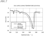
- FIG. 7 shows DSC curves during temperature elevation.
- the virgin material and the recycled material have different melting characteristics.
- the differing melting characteristics are ascribable to the presence or absence of a generated AlCuNi compound, and such differing melting characteristics are presumably the cause for the differing seizure characteristics.
- the melt obtained in step S2 has an Ni content ratio of not more than 0.1 mass%, generation of an AlCuNi compound in the produced cylinder block is suppressed, whereby deteriorations in the seizure resistance of the cylinder block are suppressed. From the standpoint of suppressing deteriorations in seizure resistance, it is more preferable that the melt obtained in step S2 has an Ni content ratio less than 0.05 mass%.
- melt obtained in step S2 has a Zn content ratio of not more than 0.3 mass%.
- FIG. 8 shows results of using thermodynamic calculation software (product name: Thermo-Calc) to calculate the proportion of the liquid phase in a recycled material having a composition shown in Table 5 (with an Ni content ratio of 0.1 mass% and a Zn content ratio of 0.3 mass%), near the melting point (specifically, 500 to 600°C).
- FIG. 8 also shows calculation results for the virgin material and the recycled material of the compositions shown in Table 4.
- Step S2 of obtaining a melt may include steps S21 , S22 and S23 as shown in FIG. 9 .
- step S21 first, at least the recycled material is melted to obtain a primary melt (step S21 ).
- the recycled material only the recycled material may be used (i.e., all of the raw material may be the recycled material), or the recycled material and a virgin material may be used in combination.
- the primary melt is subjected to a component analysis (step S22 ).
- a component analysis various known methods can be used, e.g., emission spectroscopy.
- the primary melt When the primary melt has an Ni content ratio greater than 0.1 mass%, the primary melt is diluted with a virgin material of an aluminum alloy having an Ni content ratio less than 0.1 mass% (step S23 ). This results in the finally-obtained melt having an Ni content ratio of not more than 0.1 mass%.
- the primary melt When the primary melt has an Ni content ratio of not more than 0.1 mass%, the primary melt will straightforwardly be the final melt. Note that step S23 may be followed by a component analysis of the diluted melt.
- step S2 may include step S21 of obtaining a primary melt and step S22 of subjecting the primary melt to a component analysis. This allows for determining whether the Ni content ratio in the primary melt is not more than 0.1 mass%, thereby making it easier to keep the Ni content ratio in the finally-obtained melt under control at step S2.
- step S2 may further include step S23 of, when the primary melt has an Ni content ratio greater than 0.1 mass%, diluting the primary melt with a virgin material having an Ni content ratio less than 0.1 mass%. Performing such step S23 will allow the finally-obtained melt in step S2 to have a lower Ni content ratio; therefore, even if the primary melt has an Ni content ratio greater than 0.1 mass%, the Ni content ratio in the finally-obtained melt can be not more than 0.1 mass%.
- the Si content ratio and the Ni content ratio in the melt obtained in step S2 are not less than 12 mass% and not more than 20 mass% (preferably, not less than 16 mass% and not more than 18 mass%) and not more than 0.1 mass% (preferably less than 0.05 mass%), respectively.
- the melt obtained in step S2 has a Zn content ratio of not more than 0.3 mass%.
- the melt obtained in step S2 may suitably have an exemplary composition as shown in Table 6.
- a cylinder block that is produced by the production method according to an embodiment of the present invention is suitably used for an internal combustion engine of various types of transportation apparatuses such as motorcycles, for example.
Landscapes
- Chemical & Material Sciences (AREA)
- Engineering & Computer Science (AREA)
- Mechanical Engineering (AREA)
- Materials Engineering (AREA)
- Metallurgy (AREA)
- Organic Chemistry (AREA)
- Physics & Mathematics (AREA)
- Thermal Sciences (AREA)
- Crystallography & Structural Chemistry (AREA)
- Cylinder Crankcases Of Internal Combustion Engines (AREA)
- Physical Vapour Deposition (AREA)
Abstract
Description
- The present invention relates to a method for producing an aluminum-alloy cylinder block, and more particularly to a method for producing a cylinder block that is made of an aluminum-silicon alloy having a hypereutectic composition.
- In recent years, in an attempt to reduce the weight of internal combustion engines, there has been a trend to use an aluminum alloy for cylinder blocks. Since a cylinder block is required to have high abrasion resistance, aluminum alloys which contain a large amount of Si, i.e., aluminum-silicon alloys having a hypereutectic composition, are expected to be promising aluminum alloys for cylinder blocks. In a cylinder block composed of an aluminum-silicon alloy, silicon crystal grains located on the slide surface will contribute to the improvement of abrasion resistance. Cylinder blocks made of an aluminum-silicon alloy are disclosed in International Publication No.
2004/002658 (hereinafter "Patent Document 1"), for example. - Recently, with the increase in environmental awareness, various efforts have been made to achieve carbon neutrality. The applicant is actively promoting the use of recycled materials of aluminum alloys to contribute to the realization of carbon neutrality.
- However, according to studies by the inventor, using a recycled material when producing a cylinder block that is made of an aluminum-silicon alloy having a hypereutectic composition may result in a reduced seizure resistance of the cylinder block.
- Embodiments of the present invention have been made in view of the above problems, and an objective thereof is to suppress deteriorations in the seizure resistance of an aluminum-alloy cylinder block that is produced by using a recycled material.
- The present specification discloses methods for producing an aluminum-alloy cylinder block as recited in the following Items.
- A method for producing an aluminum-alloy cylinder block, the method comprising:
- step A of providing a recycled material of an aluminum alloy containing not less than 12 mass% and not more than 20 mass% of Si;
- step B of obtaining a melt having an Ni content ratio of not more than 0.1 mass% by using the recycled material as at least a portion of a raw material; and
- step C of performing die casting by using the melt.
- A production method according to an embodiment of the present invention includes step B of obtaining a melt by using a recycled material of an aluminum alloy containing not less than 12 mass% and not more than 20 mass% of Si (i.e., an aluminum-silicon alloy having a hypereutectic composition) as at least a portion of a raw material, such that the melt obtained in step B has an Ni content ratio of not more than 0.1 mass%. Because this suppresses generation of an intermetallic compound that contains Ni within the produced cylinder block, deteriorations in the seizure resistance of the cylinder block are suppressed.
- The method of
Item 1, wherein the melt obtained in step B has a Zn content ratio of not more than 0.3 mass%. - From the standpoint of suppressing deteriorations in seizure resistance, it is more preferable that the melt obtained in step B has a Zn content ratio of not more than 0.3 mass%.
- The method of
Item - Providing a recycled material having an Ni content ratio of not more than 0.1 mass% at step A makes it easy for the melt obtained in step B to have an Ni content ratio of not more than 0.1 mass%.
- The method of any of
Items 1 to 3, wherein the melt obtained in step B has an Ni content ratio less than 0.05 mass%. - From the standpoint of suppressing deteriorations in seizure resistance, it is more preferable that the melt obtained in step B has an Ni content ratio less than 0.05 mass%.
- The method of any of
Items 1 to 4, wherein the melt obtained in step B has a Cu content ratio of not less than 3.0 mass% and not more than 5.0 mass%. - When the melt contains Cu, an improved strength after the heat treatment can be obtained. The melt may have a Cu content ratio of not less than 3.0 mass% and not more than 5.0 mass%, for example.
- The method of any of
Items 1 to 5, wherein step B comprises: - step b1 of melting at least the recycled material to obtain a primary melt; and
- step b2 of subjecting the primary melt to a component analysis.
- Step B may include step b1 of obtaining a primary melt by melting at least the recycled material and step b2 of subjecting the primary melt to a component analysis. This allows for determining whether the Ni content ratio in the primary melt is not more than 0.1 mass%, thereby making it easier to keep the Ni content ratio in the finally-obtained melt under control at step B.
- The method of
Item 6, wherein step B further comprises:
step b3 of, when the primary melt has an Ni content ratio greater than 0.1 mass%, diluting the primary melt with a virgin material of an aluminum alloy having an Ni content ratio less than 0.1 mass%. - Step B may further include step b3 of, when the primary melt has an Ni content ratio greater than 0.1 mass%, diluting the primary melt with a virgin material of an aluminum alloy having an Ni content ratio less than 0.1 mass%. Performing such step b3 will allow the finally-obtained melt in step B to have a lower Ni content ratio; therefore, even if the primary melt has an Ni content ratio greater than 0.1 mass%, the Ni content ratio in the finally-obtained melt can be not more than 0.1 mass%.
- According to embodiments of the present invention, deteriorations in the seizure resistance of an aluminum-alloy cylinder block that is produced by using a recycled material can be suppressed.
-
-
FIG. 1 is a perspective view schematically showing acylinder block 100 that may be produced by a production method according to an embodiment of the present invention. -
FIG. 2 is a plan view schematically showing enlarged a slide surface of thecylinder block 100. -
FIG. 3 is a flowchart of a production method according to an embodiment of the present invention. -
FIG. 4 is a graph showing evaluation results of seizure characteristics for cylinder blocks of Prototype Examples 1 and 2. -
FIG. 5 is a graph showing calculation results of the proportion of a liquid phase in a virgin material and a recycled material. -
FIG. 6 is a graph showing calculation results of the composition of a liquid phase in a recycled material. -
FIG. 7 is a graph showing DSC curves during temperature elevation of a virgin material and a recycled material. -
FIG. 8 is a graph showing calculation results of the proportion of a liquid phase in a recycled material having a composition shown in Table 5 (with an Ni content ratio of 0.1 mass% and a Zn content ratio of 0.3 mass%). -
FIG. 9 is a flowchart showing another implementation of step S2 of obtaining a melt. - Hereinafter, embodiments of the present invention will be described with reference to the drawings. Note that the present invention is not limited to the following embodiments.
- First, an example of a cylinder block that is produced by a production method according to an embodiment of the present invention will be described. With the production method according to an embodiment of the present invention, for example, a
cylinder block 100 shown inFIG. 1 may be produced. - The
cylinder block 100 is made of an aluminum alloy which contains Si, or more specifically, an aluminum-silicon alloy having a hypereutectic composition. - As shown in
FIG. 1 , thecylinder block 100 includes: a wall portion (referred to as a "cylinder bore wall") 103 defining acylinder bore 102; and a wall portion (referred to as a "cylinder block outer wall") 104 that surrounds thecylinder bore wall 103 to define an outline of thecylinder block 100. Between thecylinder bore wall 103 and the cylinder blockouter wall 104, awater jacket 105 for retaining a coolant is provided. - A
surface 101 of the cylinder borewall 103 facing the cylinder bore 102 defines a slide surface that comes in contact with a piston. Theslide surface 101 is shown enlarged inFIG. 2. FIG. 2 is a plan view schematically showing theslide surface 101. - As shown in
FIG. 2 , thecylinder block 100 includes a plurality ofsilicon crystal grains intermetallic compound 4 on theslide surface 101. Thesesilicon crystal grains intermetallic compound 4 are present, in a dispersed manner, in a matrix (alloy base metal) 3 of solid solution which contains aluminum. - The silicon crystal grains which are the first to crystallize out when a melt of an aluminum-silicon alloy having a hypereutectic composition is cooled are referred to as "primary-crystal silicon grains". The silicon crystal grains which then crystallize out are referred to as "eutectic silicon grains". Among the
silicon crystal grains FIG. 2 , the relatively largesilicon crystal grains 1 are the primary-crystal silicon grains. The relatively smallsilicon crystal grains 2 present between the primary-crystal silicon grains are the eutectic silicon grains. Theintermetallic compound 4 includes matter that crystallizes when the melt is cooled and matter that forms through a heat treatment. - Because the
slide surface 101 has the above structure, thecylinder block 100 can have excellent abrasion resistance. - The inventor has conducted studies concerning the use of a recycled material in producing a cylinder block that is made of an aluminum-silicon alloy having a hypereutectic composition to find that using a recycled material may result in a reduced seizure resistance of the cylinder block. Through further studies, the inventor has found that seizure is ascribable to an intermetallic compound that contains Ni (nickel). The claimed invention is based on this finding by the inventor.
- Hereinafter, with reference to
FIG. 3 , a method for producing a cylinder block according to an embodiment of the present invention will be described.FIG. 3 is a flowchart of the production method according to an embodiment of the present invention. - First, a recycled material of an aluminum alloy containing Si is provided (step S1). This aluminum alloy is an aluminum-silicon alloy having a hypereutectic composition, with an Si content ratio of, specifically, not less than 12 mass% and not more than 20 mass% (more preferably, not less than 16 mass% and not more than 18 mass%).
- Next, by using the recycled material which was provided in step S1 as at least a portion of a raw material, a melt is formed (step S2). The melt obtained in step S2 has an Ni content ratio which is not more than a predetermined value, specifically, not more than 0.1 mass%. The melt formation is carried out by melting the raw material through heating in a melting furnace. As the raw material, the recycled material may exclusively be used (i.e., all of the raw material may be the recycled material), or a combination of the recycled material and a virgin material may be used. Exclusive use of the recycled material as the raw material can further promote utilization of the recycled material.
- Next, die casting is performed by using the resultant melt (step S3). In other words, the melt is cooled within a die at a high speed and a high pressure to form a molding. At this time, the neighborhood of the slide surface is cooled at a large cooling rate (e.g., not less than 4°C/sec and not more than 400°C/sec), whereby a molding is obtained which includes silicon crystal grains that contribute to abrasion resistance near its surface. This step S3 can be performed by using, for example, a casting apparatus which is disclosed in
Patent Document 1. - Next, the molding which has been taken out of the die is subjected to one of the heat treatments commonly known as "T5", "T6", and "T7" (step S4). A T5 treatment is a treatment in which the molding is rapidly cooled (with water or the like) immediately after being taken out of the die, and thereafter subjected to artificial aging at a predetermined temperature for a predetermined period of time to obtain improved mechanical properties and dimensional stability, followed by air cooling. A T6 treatment is a treatment in which the molding is subjected to a solution treatment at a predetermined temperature for a predetermined period after being taken out of the die, then cooled with water, and thereafter subjected to artificial aging at a predetermined temperature for a predetermined period of time, followed by air cooling. A T7 treatment is a treatment for causing a stronger degree of aging than in the T6 treatment; although the T7 treatment can ensure better dimensional stability than does the T6 treatment, the resultant hardness will be lower than that obtained from the T6 treatment.
- Next, predetermined machining is performed for the molding (step S5). Specifically, a surface abutting with a cylinder head and a surface abutting with a crankcase are subjected to grinding or the like.
- Thereafter, the inner surface of the portion of the molding to become the cylinder bore wall (i.e., the surface to become the slide surface) is subjected to a process for forming the slide surface (step S6), e.g., a fine boring process, a honing process, etching, etc.
- As mentioned above, the production method according to an embodiment of the present invention includes step S2 of obtaining a melt by using a recycled material of an aluminum alloy containing not less than 12 mass% and not more than 20 mass% of Si as at least a portion of the raw material. The melt obtained in this step S2 has an Ni content ratio of not more than 0.1 mass%. As has already been described, seizure is ascribable to an intermetallic compound that contains Ni. Because the melt has an Ni content ratio of not more than 0.1 mass%, generation of an intermetallic compound that contains Ni within the produced cylinder block is suppressed, whereby deteriorations in the seizure resistance of the cylinder block are suppressed.
- From the standpoint of suppressing deteriorations in seizure resistance, it is more preferable that the melt obtained in step S2 has a Zn (zinc) content ratio of not more than 0.3 mass%. Influences of Zn on seizure will be described later.
- For example, at step S1, a recycled material having an Ni content ratio of not more than 0.1 mass% may be provided, thereby making it easy for the melt obtained in step S2 to have an Ni content ratio of not more than 0.1 mass%.
- From the standpoint of suppressing deteriorations in seizure resistance, it is more preferable that the melt obtained in step S2 has an Ni content ratio less than 0.05 mass%. Because the melt has an Ni content ratio less than 0.05 mass%, deteriorations in seizure resistance can be better suppressed.
- Although there are no particular limitations as to the content ratios of any components of the melt obtained in step S2 other than Si and Ni, an improved strength after the heat treatment can be obtained if the melt contains Cu (copper). The melt may have a Cu content ratio of not less than 3.0 mass% and not more than 5.0 mass%, for example.
- Now, results of a study on how the use of a recycled material may affect seizure resistance will be described.
- First, a cylinder block of Prototype Example 1 was produced by using a virgin material having a chemical composition shown in Table 1, and a cylinder block of Prototype Example 2 was produced by using a recycled material having a chemical composition shown in Table 1.
[Table 1] virgin material recycled material chemical composition [mass% ] Si 17 17 Cu 3.0 - 5.0 3.0 - 5.0 Fe 0.5 - 1.1 0.5 - 1.1 Mg 0.2 - 0.6 0.2 - 0.6 Zn ≦0.03 ≦1.0 Mn ≦0.03 ≦0.5 Ni ≦0.03 ≦0.5 Sn ≦0.03 ≦0.1 P 0.01 - 0.02 0.01 - 0.02 others ≦0.03 ≦0.03 - Next, with a scanning electron microscope (SEM) and a wavelength dispersive X-ray spectrometry (EPMA), the metallurgical structures of Prototype Examples 1 and 2 were observed. While an intermetallic compound of Al, Cu, and Ni (considered to be Al7Cu4Ni, which hereinafter may be referred to as an "AICuNi compound") was observed in Prototype Example 2, no such intermetallic compound was observed in Prototype Example 1.
- Then, Prototype Examples 1 and 2 were subjected to a reciprocal sliding test (SRV test) to evaluate their seizure characteristics. The test conditions were as shown below, and five evaluations were made for each of Prototype Examples 1 and 2.
- sliding counterpart: a barrel-shaped Fe test piece with an Sn-plated surface
- stroke: 2000 µm
- frequency: 10 Hz
- heater temperature: 175°C
- oil: 10 W-40 2500 µl (immersed)
- breaking-in time (constantly at 50 N): 1 minute
- load: 600 N
- test time: until seizure occurred (30 minutes maximum)
- The evaluation results of seizure characteristics are shown in
FIG. 4 . InFIG. 4 , an "×" symbolizes occurrence of seizure. As shown inFIG. 4 , a clear difference existed between Prototype Example 1 and Prototype Example 2 regarding the time until the occurrence of seizure. Specifically, the time until the occurrence of seizure was shorter in Prototype Example 2 than in Prototype Example 1. - Next, for Prototype Examples 1 and 2, the aforementioned SRV test was stopped immediately before the occurrence of seizure, and the surface of the sliding counterpart was observed. While Prototype Example 1 showed hardly any deposit on the sliding counterpart, Prototype Example 2 had some deposit on the sliding counterpart. The deposit in Prototype Example 2 was subjected to a component analysis ("chemical composition of deposit"), as shown in Table 2. Regarding the chemical composition of the deposit and the chemical composition of the recycled material (as the raw material for Prototype Example 2), the amounts of other elements were calculated against the amount of Al being defined as 100, as shown in Table 3.
[Table 2] chemical composition of deposit [ mass% ] Al Si Cu Fe Mg Zn Mn Ni Sn Ca P C O S 51.3 6 11.5 8 4.7 0 10.9 5 0.3 7 0.9 3 0.3 6 0.7 4 6.1 0 0.3 6 0.5 0 6.8 2 4.6 2 0.6 2 [Table 3] Al Si Cu Fe Mg Zn Mn Ni Sn Ca deposit 100.0 22.5 9.2 21.3 0.7 1.8 0.7 1.4 11.9 0.7 recycled material 100.0 22.6 6.0 1.1 0.5 1.3 0.7 0.7 0.1 0.0 - It can be seen from Table 2 and Table 3 that the deposit composition had more Ni and Cu than did the composition of the recycled material (i.e., the original composition). This is presumably the influence of an AlCuNi compound having been formed in the cylinder block of Prototype Example 2.
- Next, regarding the virgin material and the recycled material, thermodynamic calculation software (product name: Thermo-Calc) was used to calculate the proportion of their liquid phase near the melting point (specifically, 500 to 600°C), and their respective liquid phase compositions were calculated. The respective compositions shown in Table 4 were used for the virgin material and the recycled material in the calculations. As shown in Table 4, the content ratios of Zn, Mn, Ni, and Sn were different between the virgin material and the recycled material.
[Table 4] virgin material recycled material chemical composition [ mass% ] Si 17.0 17.0 Cu 4.5 4.5 Fe 0.8 0.8 Mg 0.4 0.4 Zn 0.03 1.0 Mn 0.03 0.50 Ni 0.03 0.50 Sn 0.03 0.10 P 0.01 0.01 Ca 0.005 0.005 -
FIG. 5 shows calculation results of the proportion of the liquid phase in the virgin material and the recycled material. It can be seen fromFIG. 5 that the melting characteristics differ between the virgin material and the recycled material. Specifically, at relatively low temperatures, the proportion of the liquid phase is higher in the virgin material than in the recycled material; at 530 to 540°C, however, the trends in the proportion of the liquid phase are reversed. At 540 to 560°C, the proportion of the liquid phase is 5 to 10% higher in the recycled material than in the virgin material. It is presumably because of such difference in melting characteristics that the time until the occurrence of seizure was shorter in the aforementioned Prototype Example 2. -
FIG. 6 shows calculation results of the composition of the liquid phase in the recycled material.FIG. 6 shows amounts of Al, Cu, Zn, Mn, Ni, and Sn against a total amount of 1.0 kg. It is deduced fromFIG. 6 that the reversal of the trends in the proportion of the liquid phase at 530 to 540°C is ascribable to the melting of Ni (i.e., melting of the intermetallic compound that contains Ni). It also appears that melting of Zn has some contribution as well. - Next, regarding the virgin material and the recycled material having the compositions shown in Table 4, a differential scanning calorimetry (DSC) was conducted in order to examine whether their melting characteristics were actually different or not.
FIG. 7 shows DSC curves during temperature elevation. - It can be seen from
FIG. 7 that a difference in melting characteristics between the virgin material and the recycled material emerges near 530 to 540°C, such that the recycled material has its peak on the lower temperature side than does the virgin material. Thus, the evaluation results of the actual melting characteristics of the virgin material and the recycled material were substantially consistent with the calculation results by the thermodynamic calculation software. - As described above, it was confirmed that the virgin material and the recycled material have different melting characteristics. As has already been described, the differing melting characteristics are ascribable to the presence or absence of a generated AlCuNi compound, and such differing melting characteristics are presumably the cause for the differing seizure characteristics.
- As described above, in the production method according to an embodiment of the present invention, because the melt obtained in step S2 has an Ni content ratio of not more than 0.1 mass%, generation of an AlCuNi compound in the produced cylinder block is suppressed, whereby deteriorations in the seizure resistance of the cylinder block are suppressed. From the standpoint of suppressing deteriorations in seizure resistance, it is more preferable that the melt obtained in step S2 has an Ni content ratio less than 0.05 mass%.
- Moreover, as has been described with reference to
FIG. 6 , melting of Zn apparently has some contribution to the differing melting characteristics as well; therefore, from the standpoint of suppressing deteriorations in seizure resistance, it may be more preferable that the melt obtained in step S2 has a Zn content ratio of not more than 0.3 mass%. -
FIG. 8 shows results of using thermodynamic calculation software (product name: Thermo-Calc) to calculate the proportion of the liquid phase in a recycled material having a composition shown in Table 5 (with an Ni content ratio of 0.1 mass% and a Zn content ratio of 0.3 mass%), near the melting point (specifically, 500 to 600°C).FIG. 8 also shows calculation results for the virgin material and the recycled material of the compositions shown in Table 4.[Table 5] recycled material chemical composition [ mass% ] Si 17.0 Cu 4.5 Fe 0.8 Mg 0.4 Zn 0.3 Mn 0.3 Ni 0.1 Sn 0.1 P 0.01 Ca 0.005 - It can be seen from
FIG. 8 that the recycled material having the composition shown in Table 5 has melting characteristics similar to those of the virgin material. - With reference to
FIG. 9 , another implementation of step S2 of obtaining a melt will be described. Step S2 of obtaining a melt may include steps S21, S22 and S23 as shown inFIG. 9 . - In the example shown in
FIG. 9 , first, at least the recycled material is melted to obtain a primary melt (step S21). As the raw material, only the recycled material may be used (i.e., all of the raw material may be the recycled material), or the recycled material and a virgin material may be used in combination. - Next, the primary melt is subjected to a component analysis (step S22). As the method of component analysis, various known methods can be used, e.g., emission spectroscopy.
- When the primary melt has an Ni content ratio greater than 0.1 mass%, the primary melt is diluted with a virgin material of an aluminum alloy having an Ni content ratio less than 0.1 mass% (step S23). This results in the finally-obtained melt having an Ni content ratio of not more than 0.1 mass%. When the primary melt has an Ni content ratio of not more than 0.1 mass%, the primary melt will straightforwardly be the final melt. Note that step S23 may be followed by a component analysis of the diluted melt.
- Thus, step S2 may include step S21 of obtaining a primary melt and step S22 of subjecting the primary melt to a component analysis. This allows for determining whether the Ni content ratio in the primary melt is not more than 0.1 mass%, thereby making it easier to keep the Ni content ratio in the finally-obtained melt under control at step S2.
- As is illustrated herein, step S2 may further include step S23 of, when the primary melt has an Ni content ratio greater than 0.1 mass%, diluting the primary melt with a virgin material having an Ni content ratio less than 0.1 mass%. Performing such step S23 will allow the finally-obtained melt in step S2 to have a lower Ni content ratio; therefore, even if the primary melt has an Ni content ratio greater than 0.1 mass%, the Ni content ratio in the finally-obtained melt can be not more than 0.1 mass%.
- As has already been described, the Si content ratio and the Ni content ratio in the melt obtained in step S2 are not less than 12 mass% and not more than 20 mass% (preferably, not less than 16 mass% and not more than 18 mass%) and not more than 0.1 mass% (preferably less than 0.05 mass%), respectively. Preferably, the melt obtained in step S2 has a Zn content ratio of not more than 0.3 mass%. Although there are no limitations as to the other components in the melt obtained in step S2, the melt obtained in step S2 may suitably have an exemplary composition as shown in Table 6.
[Table 6] chemical composition Si not less than 12 mass% and not more than 20 mass% Cu not less than 3.0 mass% and not more than 5.0 mass% Fe not less than 0.5 mass% and not more than 1.1 mass% Mg not less than 0.2 mass% and not more than 0.6 mass% Zn not less than 0 mass% and not more than 0.3 mass% Mn not less than 0 mass% and not more than 0.3 mass% Ni not less than 0 mass% and not more than 0.1 mass% Sn not less than 0 mass% and not more than 0.1 mass% P not less than 0.005 mass% and not more than 0.02 mass% Ca not less than 0 mass% and not more than 0.01 mass% remaining parts are Al and inevitable impurities - According to an embodiment of the present invention, deteriorations in the seizure resistance of an aluminum-alloy cylinder block that is produced by using a recycled material can be suppressed. A cylinder block that is produced by the production method according to an embodiment of the present invention is suitably used for an internal combustion engine of various types of transportation apparatuses such as motorcycles, for example.
Claims (7)
- A method for producing an aluminum-alloy cylinder block, the method comprising:step A of providing a recycled material of an aluminum alloy containing not less than 12 mass% and not more than 20 mass% of Si;step B of obtaining a melt having an Ni content ratio of not more than 0.1 mass% by using the recycled material as at least a portion of a raw material; andstep C of performing die casting by using the melt.
- The method of claim 1, wherein the melt obtained in step B has a Zn content ratio of not more than 0.3 mass%.
- The method of claim 1 or 2, wherein the recycled material provided in step A has an Ni content ratio of not more than 0.1 mass%.
- The method of any of claims 1 to 3, wherein the melt obtained in step B has an Ni content ratio less than 0.05 mass%.
- The method of any of claims 1 to 4, wherein the melt obtained in step B has a Cu content ratio of not less than 3.0 mass% and not more than 5.0 mass%.
- The method of any of claims 1 to 5, wherein step B comprises:step b1 of melting at least the recycled material to obtain a primary melt; andstep b2 of subjecting the primary melt to a component analysis.
- The method of claim 6, wherein step B further comprises:
step b3 of, when the primary melt has an Ni content ratio greater than 0.1 mass%, diluting the primary melt with a virgin material of an aluminum alloy having an Ni content ratio less than 0.1 mass%.
Applications Claiming Priority (1)
| Application Number | Priority Date | Filing Date | Title |
|---|---|---|---|
| JP2023073324A JP2024158265A (en) | 2023-04-27 | 2023-04-27 | Manufacturing method for aluminum alloy cylinder block |
Publications (1)
| Publication Number | Publication Date |
|---|---|
| EP4454784A1 true EP4454784A1 (en) | 2024-10-30 |
Family
ID=90826280
Family Applications (1)
| Application Number | Title | Priority Date | Filing Date |
|---|---|---|---|
| EP24171586.1A Pending EP4454784A1 (en) | 2023-04-27 | 2024-04-22 | Method for producing aluminum-alloy cylinder block |
Country Status (3)
| Country | Link |
|---|---|
| EP (1) | EP4454784A1 (en) |
| JP (1) | JP2024158265A (en) |
| TW (1) | TWI902221B (en) |
Citations (6)
| Publication number | Priority date | Publication date | Assignee | Title |
|---|---|---|---|---|
| US5290373A (en) * | 1993-04-23 | 1994-03-01 | Brunswick Corporation | Evaporable foam casting system utilizing an aluminum-silicon alloy containing a high magnesium content |
| US5845560A (en) * | 1993-06-21 | 1998-12-08 | Kabushiki Kaisha Toyoda Jidoshokki Seisakusho | Swash-plate type compressor with an abrasion resistant projecting portion on the cylinder block |
| JP2001214228A (en) * | 2000-01-28 | 2001-08-07 | Nippon Light Metal Co Ltd | Die-cast cylinder block excellent in airtightness and wear resistance and method of manufacturing the same |
| WO2004002658A1 (en) | 2002-06-26 | 2004-01-08 | Yamaha Hatsudoki Kabushiki Kaisha | Method and device for vacuum die casting of aluminum alloy, and aluminum alloy product |
| US20080163846A1 (en) * | 2004-02-27 | 2008-07-10 | Yamaha Hatsudoki Kabushiki Kaisha | Engine component part and method for producing the same |
| EP2097634A1 (en) * | 2006-12-28 | 2009-09-09 | Yamaha Hatsudoki Kabushiki Kaisha | Internal combustion engine component and method for producing the same |
Family Cites Families (2)
| Publication number | Priority date | Publication date | Assignee | Title |
|---|---|---|---|---|
| US6715458B1 (en) * | 2000-08-03 | 2004-04-06 | General Motors Corporation | Engine block crankshaft bearings |
| US20160250683A1 (en) * | 2015-02-26 | 2016-09-01 | GM Global Technology Operations LLC | Secondary cast aluminum alloy for structural applications |
-
2023
- 2023-04-27 JP JP2023073324A patent/JP2024158265A/en active Pending
-
2024
- 2024-04-15 TW TW113113915A patent/TWI902221B/en active
- 2024-04-22 EP EP24171586.1A patent/EP4454784A1/en active Pending
Patent Citations (6)
| Publication number | Priority date | Publication date | Assignee | Title |
|---|---|---|---|---|
| US5290373A (en) * | 1993-04-23 | 1994-03-01 | Brunswick Corporation | Evaporable foam casting system utilizing an aluminum-silicon alloy containing a high magnesium content |
| US5845560A (en) * | 1993-06-21 | 1998-12-08 | Kabushiki Kaisha Toyoda Jidoshokki Seisakusho | Swash-plate type compressor with an abrasion resistant projecting portion on the cylinder block |
| JP2001214228A (en) * | 2000-01-28 | 2001-08-07 | Nippon Light Metal Co Ltd | Die-cast cylinder block excellent in airtightness and wear resistance and method of manufacturing the same |
| WO2004002658A1 (en) | 2002-06-26 | 2004-01-08 | Yamaha Hatsudoki Kabushiki Kaisha | Method and device for vacuum die casting of aluminum alloy, and aluminum alloy product |
| US20080163846A1 (en) * | 2004-02-27 | 2008-07-10 | Yamaha Hatsudoki Kabushiki Kaisha | Engine component part and method for producing the same |
| EP2097634A1 (en) * | 2006-12-28 | 2009-09-09 | Yamaha Hatsudoki Kabushiki Kaisha | Internal combustion engine component and method for producing the same |
Also Published As
| Publication number | Publication date |
|---|---|
| JP2024158265A (en) | 2024-11-08 |
| TW202444484A (en) | 2024-11-16 |
| TWI902221B (en) | 2025-10-21 |
Similar Documents
| Publication | Publication Date | Title |
|---|---|---|
| US4834941A (en) | Heat-resisting high-strength Al-alloy and method for manufacturing a structural member made of the same alloy | |
| US4853179A (en) | Method of manufacturing heat resistant, high-strength structural members of sintered aluminum alloy | |
| US20110240178A1 (en) | Al-Mg-Si ALUMINUM ALLOY EXTRUDED PRODUCT EXHIBITING EXCELLENT FATIGUE STRENGTH AND IMPACT FRACTURE RESISTANCE | |
| KR101756016B1 (en) | Aluminum alloy for die casting and Method for heat treatment of manufacturing aluminum alloy using thereof | |
| US20180340243A1 (en) | Aluminum alloy material | |
| US7892482B2 (en) | Material on the basis of an aluminum alloy, method for its production, as well as use therefor | |
| JP2738999B2 (en) | High wear-resistant aluminum bronze casting alloy, sliding member using the alloy | |
| WO2015060459A1 (en) | Magnesium alloy and method for producing same | |
| US5494540A (en) | Abrasion-resistant aluminum alloy and method of preparing the same | |
| EP3170594B1 (en) | Aluminum alloy powder for hot forging of sliding component, method of producing the same, aluminum alloy forged product for sliding component, and method of producing the same | |
| CN111349827B (en) | Aluminum alloy for compressor sliding member, compressor sliding member forged product, and manufacturing method thereof | |
| KR102546211B1 (en) | Aluminum alloy | |
| US20020088509A1 (en) | Recrystallization-hardenable aluminum cast alloy and component | |
| JPS60208443A (en) | Aluminum alloy material | |
| US6706126B2 (en) | Aluminum alloy for sliding bearing and its production method | |
| KR102489980B1 (en) | Aluminum alloy | |
| EP0892075B1 (en) | Method of manufacturing a piston from an aluminium alloy. | |
| JPH07197165A (en) | High wear resistance free-cutting aluminum alloy and its manufacturing method | |
| DE102012018934A1 (en) | Preparation of aluminum-iron alloy semi-finished product e.g. brake rotor, involves casting aluminum-iron alloy containing iron, copper, vanadium and element chosen from silicon, zinc and boron, and aluminum, cooling, and extruding | |
| US6395109B1 (en) | Bar product, cylinder rods, hydraulic cylinders, and method for manufacturing | |
| TWI902221B (en) | Method for producing aluminum-alloy cylinder block | |
| JPH0457738B2 (en) | ||
| US6902324B2 (en) | Crankshaft bearing shell | |
| US6899844B2 (en) | Production method of aluminum alloy for sliding bearing | |
| JPS63183144A (en) | Titanium alloy forged parts and production thereof |
Legal Events
| Date | Code | Title | Description |
|---|---|---|---|
| PUAI | Public reference made under article 153(3) epc to a published international application that has entered the european phase |
Free format text: ORIGINAL CODE: 0009012 |
|
| STAA | Information on the status of an ep patent application or granted ep patent |
Free format text: STATUS: REQUEST FOR EXAMINATION WAS MADE |
|
| 17P | Request for examination filed |
Effective date: 20240422 |
|
| AK | Designated contracting states |
Kind code of ref document: A1 Designated state(s): AL AT BE BG CH CY CZ DE DK EE ES FI FR GB GR HR HU IE IS IT LI LT LU LV MC ME MK MT NL NO PL PT RO RS SE SI SK SM TR |
|
| P01 | Opt-out of the competence of the unified patent court (upc) registered |
Free format text: CASE NUMBER: APP_64549/2024 Effective date: 20241205 |
|
| STAA | Information on the status of an ep patent application or granted ep patent |
Free format text: STATUS: EXAMINATION IS IN PROGRESS |
|
| REG | Reference to a national code |
Ref country code: DE Ref legal event code: R079 Free format text: PREVIOUS MAIN CLASS: B22D0017000000 Ipc: B22D0021000000 |
|
| 17Q | First examination report despatched |
Effective date: 20251218 |
|
| GRAP | Despatch of communication of intention to grant a patent |
Free format text: ORIGINAL CODE: EPIDOSNIGR1 |
|
| STAA | Information on the status of an ep patent application or granted ep patent |
Free format text: STATUS: GRANT OF PATENT IS INTENDED |
|
| RIC1 | Information provided on ipc code assigned before grant |
Ipc: B22D 21/00 20060101AFI20260119BHEP Ipc: B22D 21/04 20060101ALI20260119BHEP Ipc: C22C 1/02 20060101ALI20260119BHEP Ipc: C22C 21/02 20060101ALI20260119BHEP Ipc: B22D 15/02 20060101ALI20260119BHEP Ipc: C22F 1/043 20060101ALI20260119BHEP |
|
| INTG | Intention to grant announced |
Effective date: 20260209 |
|
| GRAS | Grant fee paid |
Free format text: ORIGINAL CODE: EPIDOSNIGR3 |
|
| GRAA | (expected) grant |
Free format text: ORIGINAL CODE: 0009210 |
|
| STAA | Information on the status of an ep patent application or granted ep patent |
Free format text: STATUS: THE PATENT HAS BEEN GRANTED |