EP4454694A1 - Medical device - Google Patents
Medical device Download PDFInfo
- Publication number
- EP4454694A1 EP4454694A1 EP22911037.4A EP22911037A EP4454694A1 EP 4454694 A1 EP4454694 A1 EP 4454694A1 EP 22911037 A EP22911037 A EP 22911037A EP 4454694 A1 EP4454694 A1 EP 4454694A1
- Authority
- EP
- European Patent Office
- Prior art keywords
- operation wire
- medical device
- distal end
- device body
- wire
- Prior art date
- Legal status (The legal status is an assumption and is not a legal conclusion. Google has not performed a legal analysis and makes no representation as to the accuracy of the status listed.)
- Pending
Links
Images








Classifications
-
- A—HUMAN NECESSITIES
- A61—MEDICAL OR VETERINARY SCIENCE; HYGIENE
- A61M—DEVICES FOR INTRODUCING MEDIA INTO, OR ONTO, THE BODY; DEVICES FOR TRANSDUCING BODY MEDIA OR FOR TAKING MEDIA FROM THE BODY; DEVICES FOR PRODUCING OR ENDING SLEEP OR STUPOR
- A61M25/00—Catheters; Hollow probes
-
- A—HUMAN NECESSITIES
- A61—MEDICAL OR VETERINARY SCIENCE; HYGIENE
- A61M—DEVICES FOR INTRODUCING MEDIA INTO, OR ONTO, THE BODY; DEVICES FOR TRANSDUCING BODY MEDIA OR FOR TAKING MEDIA FROM THE BODY; DEVICES FOR PRODUCING OR ENDING SLEEP OR STUPOR
- A61M25/00—Catheters; Hollow probes
- A61M25/01—Introducing, guiding, advancing, emplacing or holding catheters
- A61M25/0105—Steering means as part of the catheter or advancing means; Markers for positioning
- A61M25/0133—Tip steering devices
- A61M25/0147—Tip steering devices with movable mechanical means, e.g. pull wires
-
- A—HUMAN NECESSITIES
- A61—MEDICAL OR VETERINARY SCIENCE; HYGIENE
- A61M—DEVICES FOR INTRODUCING MEDIA INTO, OR ONTO, THE BODY; DEVICES FOR TRANSDUCING BODY MEDIA OR FOR TAKING MEDIA FROM THE BODY; DEVICES FOR PRODUCING OR ENDING SLEEP OR STUPOR
- A61M25/00—Catheters; Hollow probes
- A61M25/01—Introducing, guiding, advancing, emplacing or holding catheters
- A61M25/0105—Steering means as part of the catheter or advancing means; Markers for positioning
-
- A—HUMAN NECESSITIES
- A61—MEDICAL OR VETERINARY SCIENCE; HYGIENE
- A61M—DEVICES FOR INTRODUCING MEDIA INTO, OR ONTO, THE BODY; DEVICES FOR TRANSDUCING BODY MEDIA OR FOR TAKING MEDIA FROM THE BODY; DEVICES FOR PRODUCING OR ENDING SLEEP OR STUPOR
- A61M25/00—Catheters; Hollow probes
- A61M25/01—Introducing, guiding, advancing, emplacing or holding catheters
- A61M25/0105—Steering means as part of the catheter or advancing means; Markers for positioning
- A61M25/0108—Steering means as part of the catheter or advancing means; Markers for positioning using radio-opaque or ultrasound markers
-
- A—HUMAN NECESSITIES
- A61—MEDICAL OR VETERINARY SCIENCE; HYGIENE
- A61M—DEVICES FOR INTRODUCING MEDIA INTO, OR ONTO, THE BODY; DEVICES FOR TRANSDUCING BODY MEDIA OR FOR TAKING MEDIA FROM THE BODY; DEVICES FOR PRODUCING OR ENDING SLEEP OR STUPOR
- A61M25/00—Catheters; Hollow probes
- A61M25/01—Introducing, guiding, advancing, emplacing or holding catheters
- A61M25/0105—Steering means as part of the catheter or advancing means; Markers for positioning
- A61M25/0133—Tip steering devices
-
- A—HUMAN NECESSITIES
- A61—MEDICAL OR VETERINARY SCIENCE; HYGIENE
- A61M—DEVICES FOR INTRODUCING MEDIA INTO, OR ONTO, THE BODY; DEVICES FOR TRANSDUCING BODY MEDIA OR FOR TAKING MEDIA FROM THE BODY; DEVICES FOR PRODUCING OR ENDING SLEEP OR STUPOR
- A61M25/00—Catheters; Hollow probes
- A61M25/01—Introducing, guiding, advancing, emplacing or holding catheters
- A61M25/0105—Steering means as part of the catheter or advancing means; Markers for positioning
- A61M25/0133—Tip steering devices
- A61M25/0147—Tip steering devices with movable mechanical means, e.g. pull wires
- A61M2025/015—Details of the distal fixation of the movable mechanical means
-
- A—HUMAN NECESSITIES
- A61—MEDICAL OR VETERINARY SCIENCE; HYGIENE
- A61M—DEVICES FOR INTRODUCING MEDIA INTO, OR ONTO, THE BODY; DEVICES FOR TRANSDUCING BODY MEDIA OR FOR TAKING MEDIA FROM THE BODY; DEVICES FOR PRODUCING OR ENDING SLEEP OR STUPOR
- A61M2205/00—General characteristics of the apparatus
- A61M2205/32—General characteristics of the apparatus with radio-opaque indicia
-
- A—HUMAN NECESSITIES
- A61—MEDICAL OR VETERINARY SCIENCE; HYGIENE
- A61M—DEVICES FOR INTRODUCING MEDIA INTO, OR ONTO, THE BODY; DEVICES FOR TRANSDUCING BODY MEDIA OR FOR TAKING MEDIA FROM THE BODY; DEVICES FOR PRODUCING OR ENDING SLEEP OR STUPOR
- A61M25/00—Catheters; Hollow probes
- A61M25/0043—Catheters; Hollow probes characterised by structural features
- A61M25/005—Catheters; Hollow probes characterised by structural features with embedded materials for reinforcement, e.g. wires, coils, braids
-
- A—HUMAN NECESSITIES
- A61—MEDICAL OR VETERINARY SCIENCE; HYGIENE
- A61M—DEVICES FOR INTRODUCING MEDIA INTO, OR ONTO, THE BODY; DEVICES FOR TRANSDUCING BODY MEDIA OR FOR TAKING MEDIA FROM THE BODY; DEVICES FOR PRODUCING OR ENDING SLEEP OR STUPOR
- A61M25/00—Catheters; Hollow probes
- A61M25/01—Introducing, guiding, advancing, emplacing or holding catheters
- A61M25/0105—Steering means as part of the catheter or advancing means; Markers for positioning
- A61M25/0133—Tip steering devices
- A61M25/0136—Handles therefor
Definitions
- the present invention relates to a medical device.
- Priority is claimed on Japanese Patent Application No. 2021-211223, filed on December 24, 2021 , the content of which is incorporated herein by reference.
- a type of medical device including an operation wire is known (for example, PTL 1).
- a plurality of hollow tubes are disposed around a central lumen, and operation wires are respectively inserted into two hollow tubes facing each other with the central lumen interposed therebetween.
- a distal end of the operation wire is fixed to a distal end part of the catheter.
- the medical device of PTL 1 is configured to perform a pulling operation of a rear end of the operation wire. Consequently, the distal end part of the catheter can be bent by selecting and pulling the operation wire.
- the present invention has been made in view of the above-described problem and provides a medical device having a structure with more excellent operability.
- a medical device including:
- Various components of a catheter according to the present embodiment are not necessarily independent entities, and a plurality of components formed as one member, one component formed of a plurality of members, a certain component as a part of another component, overlapping parts between a certain component and another component, and the like are allowed.
- a distal end part is an end part (distal end) on an insertion distal end side of a medical device 100 in each part of the medical device 100
- a proximal end part is an end part (proximal end part) on a proximal end side of the medical device 100 in each part of the medical device 100.
- an axial core means a central axis along a longitudinal direction of a medical device body 10.
- a longitudinal section of the medical device body 10 refers to a section obtained by cutting the medical device body 10 along the axial core.
- a transverse section of the medical device body 10 refers to a section obtained by cutting the medical device 100 along a plane orthogonal to the axial core.
- FIGS. 1A to 8 a first embodiment will be described using FIGS. 1A to 8 .
- a first operation wire 41 to a third operation wire 43 are shown by dashed lines.
- FIG. 2 is a sectional view taken along line A-A of FIG. 3 .
- a body case 70a of an operation part 70 is partially broken to show a structure inside the body case 70a.
- the medical device 100 includes the elongated medical device body 10, the first operation wire 41 and the second operation wire 42, each of which extends along the longitudinal direction of the medical device body 10, and the operation part 70 that is configured to individually and simultaneously pull the first operation wire 41 and the second operation wire 42.
- the first operation wire 41 and the second operation wire 42 are disposed at opposite extreme positions in the transverse section of the medical device body 10.
- a distal end of the first operation wire 41 is fixed to a distal end part 10a of the medical device body 10, and a distal end of the second operation wire 42 is fixed to the distal end part 10a of the medical device body 10 at a position on the proximal end side with respect to the distal end of the first operation wire 41.
- the opposite extreme positions mean that the first operation wire 41 and the second operation wire 42 are spaced apart from each other by 160 degrees or more in a circumferential direction of the medical device body 10, and preferably, the first operation wire 41 and the second operation wire 42 are spaced apart from each other by 170 degrees or more in the circumferential direction of the medical device body 10.
- the distal end part 10a of the medical device body 10 can be selectively bent in one direction (hereinafter, a first direction). Further, by simultaneously pulling the first operation wire 41 and the second operation wire 42, it is possible to primarily bend a region (hereinafter, a second region 14) on the proximal end side with respect to the distal end of the second operation wire 42 in a second direction while primarily bending a region (hereinafter, a first region 12) on the distal end side with respect to the distal end of the second operation wire 42 in the first direction, in the distal end part 10a of the medical device body 10, as shown in FIG. 1B .
- a region hereinafter, a second region 14
- the distal end part 10a of the medical device body 10 can be bent in a direction (second direction) opposite to the first direction. That is, since the medical device body 10 can be bent with a higher degree of freedom according to a branching direction of a branching part of a body cavity such as a blood vessel, the branching selectivity of the medical device 100 can be improved. Therefore, the operability of the medical device 100 can be improved.
- the medical device 100 is, as an example, a catheter. More specifically, for example, the medical device 100 is an intravascular catheter used by inserting the medical device body 10 into a blood vessel.
- the medical device 100 may be, for example, a guide wire used when inserting the catheter into a body cavity.
- the medical device 100 further includes a third operation wire 43 that extends along the longitudinal direction of the medical device body 10.
- the third operation wire 43 is disposed at a position near the second operation wire 42 in the transverse section of the medical device body 10, and a distal end of the third operation wire 43 is fixed to the distal end part 10a of the medical device body 10 at a position on the distal end side with respect to the distal end of the second operation wire 42.
- the distal end part 10a of the medical device body 10 can be bent in a direction substantially opposite to a direction in which the distal end part 10a of the medical device body 10 is bent by pulling the first operation wire 41.
- being disposed at a position near the second operation wire 42 means being positioned within 20 degrees from a position of the second operation wire 42 in the circumferential direction of the medical device body 10, preferably being positioned within 10 degrees from the position of the second operation wire 42.
- the first operation wire 41, and the second operation wire 42 and the third operation wire 43 are disposed at opposite extreme positions.
- the third operation wire 43 is disposed at a position near the second operation wire 42 in the transverse section of the medical device body 10, the first operation wire 41 and the third operation wire 43 are disposed at opposite extreme positions in the transverse section of the medical device body 10.
- the opposite extreme positions mean that the first operation wire 41 and the third operation wire 43 are spaced apart from each other by 160 degrees or more in the circumferential direction of the medical device body 10, and preferably, the first operation wire 41 and the third operation wire 43 are spaced apart from each other by 170 degrees or more in the circumferential direction of the medical device body 10.
- the first operation wire 41 and the second operation wire 42 are disposed at positions that are 180 degrees rotationally symmetric to each other with respect to an axial center of the medical device body 10 as a reference.
- the second operation wire 42 and the third operation wire 43 are disposed at substantially equivalent positions in the circumferential direction of the medical device body 10 with the axial center of the medical device body 10 as a reference. Therefore, the third operation wire 43 and the first operation wire 41 are disposed at positions that are 180 degrees rotationally symmetric to each other with respect to the axial center of the medical device body 10 as a reference.
- a direction in which the distal end part 10a of the medical device body 10 is bent by pulling the first operation wire 41 and a direction in which the distal end part 10a of the medical device body 10 is bent by pulling the third operation wire 43 or the second operation wire 42 are directions opposite to each other.
- the first operation wire 41, the second operation wire 42, and the third operation wire 43 are each made of a thin wire such as a metal or a resin.
- a breaking strength of the second operation wire 42 is greater than a breaking strength of the first operation wire 41.
- the first operation wire 41 and the second operation wire 42 are made of, for example, the same type of material. Meanwhile, by setting a wire diameter of the second operation wire 42 to a dimension larger than a wire diameter of the first operation wire 41, the breaking strength of the second operation wire 42 can be made greater than the breaking strength of the first operation wire 41. However, for example, by using a material having a greater breaking strength than a breaking strength of a material constituting the first operation wire 41 as a material constituting the second operation wire 42, the breaking strength of the second operation wire 42 can also be made greater than the breaking strength of the first operation wire 41.
- the third operation wire 43 and the first operation wire 41 are made of the same type of material, and a wire diameter of the third operation wire 43 is set to, for example, a substantially equivalent dimension to the wire diameter of the first operation wire 41.
- the wire diameter of the third operation wire 43 and the wire diameter of the first operation wire 41 may be set to different dimensions from each other. Further, the third operation wire 43 and the first operation wire 41 may be made of, for example, different types of materials from each other.
- the wire diameter of the first operation wire 41 and the wire diameter of the third operation wire 43 are not particularly limited, but are preferably 10 ⁇ m or more and 60 ⁇ m or less and more preferably 20 ⁇ m or more and 50 ⁇ m or less.
- the wire diameter of the second operation wire 42 is not particularly limited, but is preferably 30 ⁇ m or more and 180 ⁇ m or less, and more preferably 60 ⁇ m or more and 150 ⁇ m or less.
- the wire diameter of the second operation wire 42 is larger than the wire diameter of the first operation wire 41.
- the medical device body 10 has a lumen 20 that is open at a distal end of the medical device body 10.
- the medical device body 10 has, for example, a two-layer structure including an inner layer 22 and an outer layer 23 provided around the inner layer 22 and is configured by being laminated in the order of the inner layer 22 and the outer layer 23 from an axial core side of the medical device body 10.
- the inner layer 22 is an innermost layer of the medical device body 10 and is formed, for example, in a circular tubular shape having a constant wall thickness regardless of the position in an axial direction.
- the inner layer 22 is open at both ends, that is, the distal end and the proximal end of the medical device body 10.
- the lumen 20 is defined by an inner peripheral surface of the inner layer 22.
- the inner layer 22 is made of, for example, a fluorine-based or olefin-based thermoplastic polymer resin.
- the fluorine-based thermoplastic polymer material is not particularly limited and can include polytetrafluoroethylene (PTFE), polyvinylidene fluoride (PVDF), and perfluoroalkoxy fluororesin (PFA), and similarly, the olefin-based polymer material can include polyethylene and the like.
- the outer layer 23 is an outermost layer of the medical device body 10. For example, the majority (more than half) of a wall thickness of the medical device body 10 is occupied by a wall thickness of the outer layer 23.
- the outer layer 23 is formed, for example, in a circular tubular shape having a substantially constant wall thickness regardless of the position in the axial direction. However, an outer diameter of a distal end of a distal end part of the outer layer 23 is slightly decreased toward the distal end side, for example.
- a hydrophilic coating may be formed on an outer surface layer of the medical device body 10 as necessary.
- the lumen 20 is continuously formed from the distal end to the proximal end of the medical device body 10 and is open at the distal end and the proximal end of the medical device body 10, respectively.
- the medical device body 10 further includes a first hollow tube 31, a second hollow tube 32, and a third hollow tube 33 that are each embedded in the outer layer 23.
- the first operation wire 41 is inserted through the first hollow tube 31, the second operation wire 42 is inserted through the second hollow tube 32, and the third operation wire 43 is inserted through the third hollow tube 33.
- the first hollow tube 31, the second hollow tube 32, and the third hollow tube 33 are each a sub-lumen tube, and the inner lumens of these sub-lumen tubes are sub-lumens. That is, each of the operation wires (the first operation wire 41, the second operation wire 42, and the third operation wire 43) is inserted through the sub-lumen.
- Inner diameters of the first hollow tube 31, the second hollow tube 32, and the third hollow tube 33 are smaller than the inner diameter of the lumen 20.
- the second operation wire 42 and the second hollow tube 32, and the third operation wire 43 and the third hollow tube 33 are disposed side by side in a radial direction of the medical device body 10.
- the third operation wire 43 and the third hollow tube 33 are disposed radially outward of the second operation wire 42 and the second hollow tube 32 (at a position away from the axial core of the medical device body 10) in the medical device body 10.
- the second operation wire 42 and the second hollow tube 32, and the third operation wire 43 and the third hollow tube 33 may be disposed side by side in the circumferential direction of the medical device body 10.
- a spaced distance between the axial core of the medical device body 10 and an axial core of the second operation wire 42 (or an axial core of the second hollow tube 32) may be, for example, substantially equivalent to a spaced distance between the axial core of the medical device body 10 and an axial core of the third operation wire 43 (or an axial core of the third hollow tube 33).
- a resin material such as polytetrafluoroethylene (PTFE), polyvinylidene fluoride (PVDF), or perfluoroalkoxy fluororesin (PFA), polyethylene, or the like can be used.
- PTFE polytetrafluoroethylene
- PVDF polyvinylidene fluoride
- PFA perfluoroalkoxy fluororesin
- a ring-shaped first marker 61 made of a radiopaque metal material is embedded in the distal end part 10a of the medical device body 10.
- the first marker 61 is disposed coaxially with the lumen 20 and around the lumen 20.
- the first marker 61 is disposed, for example, around a reinforcing layer 51.
- a ring-shaped second marker 63 made of a radiopaque metal material is embedded in a part on the proximal end side with respect to a part where the first marker 61 is embedded.
- the second marker 63 is disposed coaxially with the lumen 20 and around the lumen 20.
- the second marker 63 is disposed, for example, around the reinforcing layer 51.
- a through-hole (not shown) that penetrates a wall thickness portion of the second marker 63 in the axial direction may be formed in the second marker 63.
- a portion of the second marker 63 in the circumferential direction may be interrupted, and the second marker 63 may have a substantially C-like shape when viewed in the axial direction.
- the first marker 61 and the second marker 63 have the same inner diameter.
- an outer diameter of the first marker 61 is larger than an outer diameter of the second marker 63.
- the distal end of the first operation wire 41 and the distal end of the first hollow tube 31 are fixed to a proximal end of the first marker 61 by, for example, soldering, welding, a mechanical coupling that generates frictional resistance, or the like (not shown).
- the distal end of the second operation wire 42 and the distal end of the second hollow tube 32 are fixed to a proximal end of the second marker 63 by, for example, soldering, welding, a mechanical coupling that generates frictional resistance, or the like (not shown).
- the distal end of the third operation wire 43 and the distal end of the third hollow tube 33 are fixed to the proximal end of the first marker 61 by, for example, soldering, welding, a mechanical coupling that generates frictional resistance, or the like (not shown).
- the distal end of the first operation wire 41 and the distal end of the third operation wire 43 are disposed at the same position (substantially the same position) in the axial direction of the medical device body 10.
- the medical device 100 includes the first marker 61 that is fixed to the distal end part 10a of the medical device body 10 and the second marker 63 that is fixed to the distal end part 10a of the medical device body 10 at a position on the proximal end side with respect to the first marker 61, and the distal end of the first operation wire 41 and the distal end of the third operation wire 43 are fixed to the first marker 61, and the distal end of the second operation wire 42 is fixed to the second marker 63.
- the number of markers provided in the medical device 100 may be, for example, two or more.
- a region on the distal end side with respect to a distal end of the second marker 63 is the first region 12, and a region on the proximal end side with respect to the distal end of the second marker 63 is the second region 14.
- a length of the first region 12 and a length of the second region 14 can be adjusted by setting the distance between the first marker 61 and the second marker 63 in the axial direction of the medical device body 10 to a desired distance.
- the distal end part of the first operation wire 41 is indirectly fixed to the distal end part 10a of the medical device body 10 by being fixed to the first marker 61
- the distal end part of the third operation wire 43 is indirectly fixed to the distal end part 10a of the medical device body 10 by being fixed to the second marker 63.
- the first operation wire 41 is routed from a region on the proximal end side with respect to the second marker 63 to a region on the distal end side with respect to the second marker 63 through a portion of the medical device body 10 on a radially outer side with respect to a disposition region of the second marker 63.
- the first hollow tube 31 through which the first operation wire 41 is inserted is also routed from the region on the proximal end side with respect to the second marker 63 to the region on the distal end side with respect to the second marker 63 through the portion of the medical device body 10 on the radially outer side with respect to the disposition region of the second marker 63.
- a spaced distance in the radial direction between the axial core of the medical device body 10 and the axial core of the first operation wire 41 (or the axial core of the first hollow tube 31) may be, for example, substantially equivalent to the spaced distance between the axial core of the medical device body 10 and the axial core of the second operation wire 42 (or the axial core of the second hollow tube 32).
- the third operation wire 43 is routed from the region on the proximal end side with respect to the second marker 63 to the region on the distal end side with respect to the second marker 63 through the portion of the medical device body 10 on the radially outer side with respect to the disposition region of the second marker 63.
- the third hollow tube 33 through which the third operation wire 43 is inserted is also routed from the region on the proximal end side with respect to the second marker 63 to the region on the distal end side with respect to the second marker 63 through the portion of the medical device body 10 on the radially outer side with respect to the disposition region of the second marker 63.
- the spaced distance in the radial direction between the axial core of the medical device body 10 and the axial core of the third operation wire 43 (or the axial core of the third hollow tube 33) may be, for example, substantially equivalent to the spaced distance between the axial core of the medical device body 10 and the axial core of the second operation wire 42 (or the axial core of the second hollow tube 32).
- the medical device body 10 includes the reinforcing layer 51.
- a bending stiffness of the reinforcing layer 51 on the proximal end side with respect to the second marker 63 is greater than a bending stiffness of the reinforcing layer 51 on the distal end side with respect to the second marker 63.
- a bending stiffness of the medical device body 10 on the proximal end side with respect to the second marker 63 is greater than a bending stiffness of the medical device body 10 on the distal end side with respect to the second marker 63.
- the reinforcing layer 51 includes, for example, a blade layer 53 embedded in the outer layer 23 and a winding wire 55 embedded in the outer layer 23.
- Each of the blade layer 53 and the winding wire 55 extends from the distal end side to a proximal end part 10b of the medical device body 10.
- a distal end of the blade layer 53 is disposed, for example, at a position substantially equivalent to a position of the distal end of the second marker 63 in the axial direction.
- a distal end of the winding wire 55 is disposed, for example, at a position substantially equivalent to a position of a distal end of the first marker 61 in the axial direction.
- the region on the proximal end side with respect to the second marker 63 is reinforced by the blade layer 53 and the winding wire 55, and the region on the distal end side with respect to the second marker 63 is reinforced by the winding wire 55. Therefore, the bending stiffness of the medical device body 10 on the proximal end side with respect to the second marker 63 is greater than the bending stiffness of the medical device body 10 on the distal end side with respect to the second marker 63.
- the blade layer 53 is formed by braiding a plurality of wires.
- the blade layer 53 is disposed, for example, around the inner layer 22.
- the first hollow tube 31, the second hollow tube 32, and the third hollow tube 33 are disposed, for example, radially outward of the reinforcing layer 51 (at a position away from the axial core of the medical device body 10) in the medical device body 10.
- a material of the wire constituting the blade layer 53 is preferably, for example, a metal material such as stainless steel or tungsten, but may be a resin material.
- the winding wire 55 is wound around the medical device body 10 radially outward of the reinforcing layer 51, the first hollow tube 31, the second hollow tube 32, and the third hollow tube 33.
- a material of the wire constituting the winding wire 55 is preferably, for example, a metal material such as stainless steel or tungsten, but may be a resin material.
- the distal end of the blade layer 53 may be disposed, for example, at a position substantially equivalent to the position of the distal end of the first marker 61 (the position of the distal end of the winding wire 55).
- the blade layer 53 in the first region 12 is composed of a fewer number of wires than the number of wires in the second region 14, or that an opening width of the mesh of the blade layer 53 in the first region 12 is larger than an opening width of the mesh of the blade layer 53 in the second region 14.
- a configuration can be employed in which the bending stiffness of the medical device body 10 on the proximal end side with respect to the second marker 63 is greater than the bending stiffness of the medical device body 10 on the distal end side with respect to the second marker 63.
- the reinforcing layer 51 may include, for example, a coil layer (not shown) formed by winding a wire a plurality of times, instead of the blade layer 53.
- the medical device 100 includes a hub 91 provided at the proximal end part of the medical device body 10.
- the hub 91 includes a coupling portion 93 for inserting an injector (syringe) (not shown) into a proximal end of the hub 91.
- a screw groove is formed on an outer periphery of the coupling portion 93 such that the syringe can be attachably and detachably fixed.
- the hub 91 includes two blade portions 92 that face each other with the axial core of the hub 91 interposed therebetween and that are provided on an outer periphery of the hub 91.
- the proximal end part of the medical device body 10 is inserted into and fixed to a distal end part of the hub 91. Consequently, the lumen 20 inside the medical device body 10 and an internal space of the hub 91 communicate with each other.
- the body case 70a of the operation part 70 which will be described below, is connected and fixed to the distal end side of the hub 91.
- the medical device 100 includes the operation part 70 for performing the bending operation of the distal end part 10a of the medical device body 10.
- the operation part 70 an operation of selectively pulling one of the first operation wire 41 or the third operation wire 43, and an operation of individually and simultaneously pulling the first operation wire 41 and the second operation wire 42 are possible.
- the operation part 70 includes, for example, the body case 70a and a first rotation member 71 that is pivotally supported to be rotatable with respect to the body case 70a.
- the first rotation member 71 is, for example, a pulley.
- a certain member being rotatable is not limited to an aspect in which the member is rotatable by 360 degrees or more, but also includes an aspect in which the member is only swingable in a predetermined angular range of less than 360 degrees.
- a first dial operation portion 74 having a disc-like shape or the like is engaged with the first rotation member 71 coaxially with the first rotation member 71. Since the first dial operation portion 74 is pivotally supported to be rotatable with respect to the body case 70a, the first rotation member 71 is indirectly and pivotally supported to be rotatable with respect to the body case 70a.
- the proximal end part 10b of the medical device body 10 is led to the proximal end side of the body case 70a through the inside of the body case 70a, and is inserted into and fixed to the distal end part of the hub 91.
- a rotary shaft of the first dial operation portion 74 extends in a direction orthogonal to an axial core direction of the medical device body 10 in the body case 70a.
- the first dial operation portion 74 is exposed to the outside of the body case 70a, and an operator who operates the medical device 100 can operate the first dial operation portion 74 from the outside of the body case 70a.
- the operation part 70 includes, for example, a first slider operation portion 81 that is fixed to the body case 70a to be slidable in the axial direction.
- a slide hole (not shown) that extends in the axial direction is formed in the body case 70a, and the first slider operation portion 81 is guided by the slide hole and is slidable in the axial direction relative to the body case 70a.
- the first slider operation portion 81 is exposed to the outside of the body case 70a via the slide hole, and the operator who operates the medical device 100 can perform an operation of sliding the first slider operation portion 81 toward the proximal end side or the distal end side from the outside of the body case 70a.
- each of the first operation wire 41, the second operation wire 42, and the third operation wire 43 is led out from the medical device body 10 in the body case 70a.
- a proximal end part of the first operation wire 41 is, for example, wound around the first rotation member 71 by one and a half turns, and a proximal end of the first operation wire 41 is fixed to the first rotation member 71.
- a proximal end part of the third operation wire 43 is, for example, wound around the first rotation member 71 by one and a half turns, and a proximal end of the third operation wire 43 is fixed to the first rotation member 71.
- a winding direction of the first operation wire 41 and a winding direction of the third operation wire 43 with respect to the first rotation member 71 are directions opposite to each other.
- the third operation wire 43 out of the first operation wire 41 and the third operation wire 43 is selectively pulled toward the proximal end side.
- a proximal end of the second operation wire 42 is fixed to, for example, the first slider operation portion 81.
- simultaneously pulling the first operation wire 41 and the second operation wire 42 means that there is a timing at which both the first operation wire 41 and the second operation wire 42 are pulled together. This does not necessarily mean that the starting timing of pulling both the first operation wire 41 and the second operation wire 42 is the same, nor does it mean that the timing of finishing pulling both the first operation wire 41 and the second operation wire 42 is the same.
- the operation part 70 includes, for example, a tension release mechanism 86 (refer to FIGS. 7A to 7D ) that releases a tension equal to or greater than a predetermined tension applied to the first operation wire 41.
- the tension release mechanism 86 includes, for example, an engagement recessed portion 86a formed in the first rotation member 71 and an engagement protruding portion 86b formed on the first dial operation portion 74.
- an opening portion penetrating the first rotation member 71 in a thickness direction is formed in a central part of the first rotation member 71.
- a peripheral edge part of the opening portion includes, for example, a plurality of recesses and protrusions in which the recesses and the protrusions are alternately disposed along a circumferential direction of the first rotation member 71, and a plurality of the engagement recessed portions 86a are formed by the recesses and the protrusions.
- a pair of engagement protruding portions 86b are formed on the first dial operation portion 74.
- Each of the pair of engagement protruding portions 86b is formed in a shape of protruding toward a radially outer side.
- the pair of engagement protruding portions 86b are disposed at positions that are 180 degrees rotationally symmetric to each other with respect to an axial center of the first dial operation portion 74 as a reference.
- a pair of slit portions 86c penetrating the first dial operation portion 74 in a thickness direction is formed in the first dial operation portion 74.
- the pair of slit portions 86c are disposed at positions that are 180 degrees rotationally symmetric to each other with respect to the axial center of the first dial operation portion 74 as a reference.
- each slit portion 86c forms, for example, an arc shape protruding toward the radially outer side.
- Each slit portion 86c is formed, whereby the first dial operation portion 74 is elastically deformable toward a radially inner side.
- each engagement protruding portion 86b is engaged with one engagement recessed portion 86a of the plurality of engagement recessed portions 86a.
- the distal end part 10a of the medical device body 10 is bent toward a side (hereinafter, the second direction) of the third hollow tube 33 through which the third operation wire 43 is inserted, with the axial core of the medical device body 10 as a reference.
- the first direction and the second direction are directions included in the same plane (hereinafter, a first virtual plane) and are directions opposite to each other.
- the first region 12 is primarily bent in the first direction
- the second region 14 is primarily bent in the second direction. That is, in a case where a tension is applied to the second operation wire 42, the distal end part 10a of the medical device body 10 is bent toward a side (third hollow tube 33 side) of the second hollow tube 32 through which the second operation wire 42 is inserted, with the axial core of the medical device body 10 as a reference in a region on the proximal end side with respect to the first region 12. Therefore, a combined motion occurs in which a motion of primarily bending the second region 14 in the second direction by pulling the second operation wire 42 and a motion of primarily bending the first region 12 in the first direction by pulling the first operation wire 41.
- the operation of pulling the second operation wire 42 may be performed alone.
- the second region 14 is primarily bent in the second direction.
- the operation of selectively bending the distal end part 10a of the medical device body 10 in the first direction, the operation of selectively bending the distal end part 10a of the medical device body 10 in the second direction, and the operation of primarily bending the first region 12 in the first direction and primarily bending the second region 14 in the second direction are possible. Therefore, the branching selectivity of the medical device 100 at each branching part of the body cavity (the blood vessel or the like) is improved.
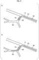
- the distal end part 10a when inserting the distal end part 10a into each branching part (branching parts 310 to 330 shown in FIG. 9 ) of the body cavity (the blood vessel or the like), the distal end part 10a is bent in the second direction by the operation of pulling the third operation wire 43 at a timing at which the distal end of the distal end part 10a approaches the second branching part 320 that branches from the first branching part 310, as shown in (a) of FIG. 9 . Consequently, the distal end part 10a can be inserted into the second branching part 320.
- the distal end part 10a tends to maintain a state in which the second hollow tube 32 (second operation wire 42) side is located most inwardly (in-course) of the curvature with the axial core of the medical device body 10 as a reference, so that the rotation by the rotation operation is less likely to be transmitted to the medical device body 10.
- the medical device body 10 is restrained from rotating around the axis, thereby entering a backed-up state.
- the distal end part 10a is bent in a substantially S-like shape and inserted into the third branching part 330 as shown in (b) of FIG. 9 .
- the breaking strength of the second operation wire 42 is greater than the breaking strength of the first operation wire 41.
- the first region 12 can be primarily bent in the first direction while maintaining a state in which the second region 14 is primarily bent in the second direction.
- the medical device body 10 includes the reinforcing layer 51.
- the bending stiffness of the reinforcing layer 51 on the proximal end side with respect to the second marker 63 is greater than the bending stiffness of the reinforcing layer 51 on the distal end side with respect to the second marker 63.
- the bending stiffness of the medical device body 10 on the proximal end side with respect to the second marker 63 is greater than the bending stiffness of the medical device body 10 on the distal end side with respect to the second marker 63.
- the first region 12 can be primarily bent in the first direction while maintaining a state in which the second region 14 is primarily bent in the second direction when simultaneously pulling the first operation wire 41 and the second operation wire 42.
- the maximum value of the tension applicable to the second operation wire 42 by the pulling by the operation part 70 is greater than the maximum value of the tension applicable to the first operation wire 41 by the pulling by the operation part 70.
- the backup capability of the first operation wire 41 with respect to the second operation wire 42 and the third operation wire 43 can be sufficiently ensured. Therefore, more reliably, the first region 12 can be primarily bent in the first direction while maintaining a state in which the second region 14 is primarily bent in the second direction when simultaneously pulling the first operation wire 41 and the second operation wire 42.
- the engagement between the engagement recessed portion 86a and the engagement protruding portion 86b is temporarily released, and the first dial operation portion 74 is configured to rotate without engagement with respect to the first rotation member 71. That is, the tension when the first dial operation portion 74 rotates without engagement with respect to the first rotation member 71 is the maximum value of the tension applicable to the first operation wire 41.
- the first rotation member 71 is elastically deformed toward the radially inner side, and the engagement between the engagement recessed portion 86a and the engagement protruding portion 86b is temporarily released. Consequently, the first dial operation portion 74 rotates without engagement with respect to the first rotation member 71 (the rotation of the first dial operation portion 74 is not transmitted to the first rotation member 71).
- the medical device 100 is configured such that the maximum value of the tension applicable to the first operation wire 41 (the tension when the first dial operation portion 74 rotates without engagement with respect to the first rotation member 71) is smaller than the tension applied to the second operation wire 42 when the first slider operation portion 81 is slid toward the proximal end side to the maximum. Therefore, it is possible to restrain the tension applied to the first operation wire 41 by the pulling by the operation part 70 from exceeding the maximum value of the tension applicable to the second operation wire 42 by the pulling by the operation part 70.
- the maximum value of the tension applicable to the first operation wire 41 by the pulling by the operation part 70 can be set as appropriate, for example, based on the depth dimension (radial dimension) of the engagement recessed portion 86a, the depth dimension or the length dimension (circumferential dimension) of the slit portion 86c, the elastic force (spring force) of the first rotation member 71, and the like.
- the maximum value of the tension applicable to the second operation wire 42 by the pulling by the operation part 70 can be set as appropriate, for example, based on the maximum stroke of the first slider operation portion 81 (the axial dimension of the slide hole).
- the maximum value of the tension applicable to the second operation wire 42 by the pulling by the operation part 70 is greater than the maximum value of the tension applicable to the third operation wire 43 by the pulling by the operation part 70.
- the medical device 100 is configured such that the maximum value of the tension applicable to the third operation wire 43 (the tension when the first dial operation portion 74 rotates without engagement with respect to the first rotation member 71) is smaller than the tension applied to the second operation wire 42 when the first slider operation portion 81 is slid toward the proximal end side to the maximum.
- FIG. 11 is a sectional view taken along line A-A of FIG. 12 .
- the medical device 100 according to the present embodiment is different from the medical device 100 according to the above-described first embodiment in the points to be described below and is configured similarly to the medical device 100 according to the above-described first embodiment in other points.
- the medical device 100 further includes a fourth operation wire 44 that extends along the longitudinal direction of the medical device body 10.
- the fourth operation wire 44 is disposed at a position near the first operation wire 41 in the transverse section of the medical device body 10, and a distal end of the fourth operation wire 44 is fixed to the distal end part 10a of the medical device body 10 at a position on the proximal end side with respect to the distal end of the third operation wire 43.
- a breaking strength of the fourth operation wire 44 is greater than the breaking strength of the third operation wire 43.
- the first region 12 can be primarily bent in the second direction, and the second region 14 can be primarily bent in the first direction. That is, since an operation similar to the bending operation performed by the operation of simultaneously pulling the first operation wire 41 and the second operation wire 42 (here, motions that are 180 degrees rotationally symmetric to each other with respect to the axial core of the medical device body 10 as a reference) can be achieved even with an operation of simultaneously pulling the third operation wire 43 and the fourth operation wire 44, a need to perform the torque rotation operation of rotating the medical device body 10 around the axis prior to the bending operation can be eliminated, or the rotation amount in the torque rotation operation can be reduced. Therefore, the operability of the medical device 100 can be improved.
- the third operation wire 43 and the fourth operation wire 44 are disposed at opposite extreme positions in the transverse section of the medical device body 10.
- the opposite extreme positions mean that the third operation wire 43 and the fourth operation wire 44 are spaced apart from each other by 160 degrees or more in the circumferential direction of the medical device body 10, and preferably, the third operation wire 43 and the fourth operation wire 44 are spaced apart from each other by 170 degrees or more in the circumferential direction of the medical device body 10.
- the fourth operation wire 44 and the first operation wire 41 are disposed at substantially equivalent positions in the circumferential direction of the medical device body 10 with the axial center of the medical device body 10 as a reference. Therefore, the fourth operation wire 44 is disposed at a position that is 180 degrees rotationally symmetric to the second operation wire 42 and the third operation wire 43 with respect to the axial center of the medical device body 10 as a reference.
- a direction in which the distal end part 10a of the medical device body 10 is bent by pulling the fourth operation wire 44 and a direction in which the distal end part 10a of the medical device body 10 is bent by pulling the third operation wire 43 (or the second operation wire 42) are directions opposite to each other.
- the medical device 100 includes a fourth hollow tube 34 that is embedded in the outer layer 23, and the fourth operation wire 44 is inserted through the fourth hollow tube 34.
- the fourth hollow tube 34 is also a sub-lumen tube, and the inner lumen of the sub-lumen tube is a sub-lumen, similar to the first hollow tube 31 to the third hollow tube 33. That is, the fourth operation wire 44 is inserted through the sub-lumen.
- An inner diameter of the fourth hollow tube 34 is smaller than the inner diameter of the lumen 20.
- the fourth operation wire 44 is made of a thin wire such as a metal or a resin, similar to the first operation wire 41 to the third operation wire 43.
- a wire diameter of the fourth operation wire 44 is set to be, for example, substantially equivalent to the wire diameter of the second operation wire 42. Therefore, the wire diameter of the fourth operation wire 44 is larger than the wire diameter of the first operation wire 41 and the wire diameter of the third operation wire 43.
- the wire diameter of the fourth operation wire 44 is not particularly limited, but is, for example, preferably 30 ⁇ m or more and 180 ⁇ m or less and more preferably 60 ⁇ m or more and 150 ⁇ m or less.
- the distal end of the fourth operation wire 44 and the distal end of the fourth hollow tube 34 are fixed to the proximal end of the second marker 63. Therefore, the distal end of the second operation wire 42 and the distal end of the fourth operation wire 44 are fixed at equivalent positions in the longitudinal direction of the medical device body 10.
- the distal end of the first operation wire 41 and the distal end of the third operation wire 43 are fixed at positions on the distal end side with respect to the positions where the distal end of the second operation wire 42 and the distal end of the fourth operation wire 44 are fixed.
- an operation of individually pulling the fourth operation wire 44 toward the proximal end side and an operation of simultaneously pulling the third operation wire 43 and the fourth operation wire 44 toward the proximal end side can be performed with respect to the operation part 70.
- simultaneously pulling the third operation wire 43 and the fourth operation wire 44 means that there is a timing at which both the third operation wire 43 and the fourth operation wire 44 are pulled together. This does not necessarily mean that the starting timing of pulling both the third operation wire 43 and the fourth operation wire 44 is the same, nor does it mean that the timing of finishing pulling both the third operation wire 43 and the fourth operation wire 44 is the same.
- the operation part 70 further includes a second slider operation portion 84 that is fixed to the body case 70a to be slidable in the axial direction.
- the second slider operation portion 84 is configured similarly to the first slider operation portion 81, for example. Therefore, a slide hole (not shown) for guiding the second slider operation portion 84 along the axial direction is formed in the body case 70a.
- the first slider operation portion 81 and the second slider operation portion 84 are disposed at positions that are 180 degrees rotationally symmetric to each other with respect to the axial core of the medical device body 10 as a reference.
- the second slider operation portion 84 is exposed to the outside of the body case 70a, and the operator who operates the medical device 100 can perform an operation of sliding the second slider operation portion 84 from the outside of the body case 70a.
- a proximal end of the fourth operation wire 44 is fixed to, for example, the second slider operation portion 84.
- the maximum value of the tension applicable to the fourth operation wire 44 by the pulling by the operation part 70 is greater than the maximum value of the tension applicable to the third operation wire 43 (first operation wire 41) by the pulling by the operation part 70.
- the first region 12 can be primarily bent in the second direction, and the second region 14 can be primarily bent in the first direction.
- a configuration is employed in which a tension required to rotate the first dial operation portion 74 without engagement is smaller than the tension applied to the fourth operation wire 44 when the second slider operation portion 84 is slid toward the proximal end side to the maximum.
- FIGS. 14 to 18 Next, a third embodiment will be described using FIGS. 14 to 18 .
- the medical device 100 according to the present embodiment is different from the medical device 100 according to the above-described first and second embodiments in the points to be described below and is configured similarly to the medical device 100 according to the above-described first and second embodiments in other points.
- the medical device 100 further includes a fifth operation wire 45 that extends along the longitudinal direction of the medical device body 10.
- the fifth operation wire 45 is disposed in a region between the disposition region of the first operation wire 41 and the fourth operation wire 44 and the disposition region of the second operation wire 42 and the third operation wire 43 in the circumferential direction of the transverse section of the medical device body 10.
- a distal end of the fifth operation wire 45 is fixed to the distal end part 10a of the medical device body 10 at a position on the distal end side with respect to the distal end of the second operation wire 42 and the distal end of the fourth operation wire 44.
- the distal end part 10a of the medical device body 10 can be bent in a direction different from the first direction and the second direction, so that the branching selectivity of the medical device 100 at each branching part of the body cavity (the blood vessel or the like) can be further improved.
- the fifth operation wire 45 is preferably disposed at a position that is at least approximately 45 degrees different from the disposition region of the first operation wire 41 and the fourth operation wire 44 (or the disposition region of the second operation wire 42 and the third operation wire 43) and more preferably disposed at a position that is at approximately 90 degrees different, in the circumferential direction.
- the distal end of the fifth operation wire 45 and the distal end of the first operation wire 41 (and the third operation wire 43) are fixed at equivalent positions in the longitudinal direction of the medical device body 10.
- the fifth operation wire 45, and the first operation wire 41 and the third operation wire 43 are disposed at positions different from each other by approximately 90 degrees in the circumferential direction of the medical device body 10.
- the fifth operation wire 45, and the third operation wire 43 and the fourth operation wire 44 are disposed at positions different from each other by approximately 90 degrees in the circumferential direction of the medical device body 10.
- the medical device 100 further includes, for example, a sixth operation wire 46 that extends along the longitudinal direction of the medical device body 10.
- the distal end of the fifth operation wire 45 and a distal end of the sixth operation wire 46 are fixed at equivalent positions in the longitudinal direction of the medical device body 10. Therefore, the distal end of the sixth operation wire 46 and the distal end of the first operation wire 41 (and the third operation wire 43) are fixed at equivalent positions in the longitudinal direction of the medical device body 10.
- the sixth operation wire 46 and the fifth operation wire 45 are disposed at positions that are 180 degrees rotationally symmetric to each other with respect to the axial center of the medical device body 10 as a reference. Therefore, the sixth operation wire 46 is disposed in a region between the disposition region of the first operation wire 41 and the fourth operation wire 44 and the disposition region of the second operation wire 42 and the third operation wire 43 in the circumferential direction of the transverse section of the medical device body 10.
- the sixth operation wire 46, and the first operation wire 41 and the third operation wire 43 are spaced apart from each other by approximately 90 degrees in the circumferential direction of the medical device body 10
- the sixth operation wire 46, and the third operation wire 43 and the fourth operation wire 44 are spaced apart from each other by approximately 90 degrees in the circumferential direction of the medical device body 10.
- a direction in which the distal end part 10a of the medical device body 10 is bent by pulling the fifth operation wire 45 (hereinafter, a third direction) and a direction in which the distal end part 10a of the medical device body 10 is bent by pulling the sixth operation wire 46 (hereinafter, a fourth direction) are directions opposite to each other.
- the medical device 100 includes a fifth hollow tube 35 and a sixth hollow tube 36 that are embedded in the outer layer 23.
- the fifth operation wire 45 is inserted through the fifth hollow tube 35
- the sixth operation wire 46 is inserted through the sixth hollow tube 36.
- the fifth hollow tube 35 and the sixth hollow tube 36 are sub-lumen tubes, and the inner lumens of the sub-lumen tubes are sub-lumens, similar to the first hollow tube 31 to the third hollow tube 33.
- An inner diameter of the fifth hollow tube 35 and an inner diameter of the sixth hollow tube 36 are smaller than the inner diameter of the lumen 20.
- the fifth operation wire 45 and the sixth operation wire 46 are made of thin wires such as metals or resins, similar to the first operation wire 41 to the third operation wire 43.
- the breaking strengths of the second operation wire 42 and the fourth operation wire 44 are larger than the breaking strengths of the fifth operation wire 45 and the sixth operation wire 46. More specifically, in the case of the present embodiment, the first operation wire 41 to the sixth operation wire 46 are made of the same type of material. However, the first operation wire 41 to the sixth operation wire 46 are made of, for example, different types of materials from each other.
- the breaking strengths of the second operation wire 42 and the fourth operation wire 44 can be made greater than the breaking strengths of the fifth operation wire 45 and the sixth operation wire 46.
- the breaking strength of the fourth operation wire 44 can also be made greater than the breaking strengths of the fifth operation wire 45 and the sixth operation wire 46.
- the wire diameter of the fifth operation wire 45 and the wire diameter of the sixth operation wire 46 are not particularly limited, but are preferably 10 ⁇ m or more and 60 ⁇ m or less and more preferably 20 ⁇ m or more and 50 ⁇ m or less.
- the distal end of the fifth hollow tube 35 and the distal end of the fifth operation wire 45 are fixed to the proximal end of the first marker 61.
- the distal end of the sixth hollow tube 36 and the distal end of the sixth operation wire 46 are fixed to the proximal end of the first marker 61.
- the number of operation wires whose distal ends are fixed at positions on the distal end side with respect to the positions where the distal end of the second operation wire 42 and the distal end of the fourth operation wire 44 are fixed is equal to or greater than the number of operation wires whose distal ends are fixed at equivalent positions to the second operation wire 42 and the fourth operation wire 44.
- the equivalent position means that the spaced distance between the distal ends of the respective operation wires in the axial direction of the medical device body 10 is smaller than the outer diameter of the medical device body 10.
- the axial dimension of the marker may be larger than the outer diameter of the medical device body 10, but is preferably smaller than the outer diameter of the medical device body 10.
- an operation of selectively pulling either the fifth operation wire 45 or the sixth operation wire 46 toward the proximal end side, an operation of individually and simultaneously pulling the fifth operation wire 45 and the second operation wire 42 (or the fourth operation wire 44), and an operation of individually and simultaneously pulling the sixth operation wire 46 and the second operation wire 42 (or the fourth operation wire 44) are possible with respect to the operation part 70.
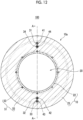
- the operation part 70 includes a second rotation member 76 that is pivotally supported to be rotatable with respect to the body case 70a, and a second dial operation portion 78 that is fixed to the second rotation member 76.
- the second rotation member 76 is configured similarly to the first rotation member 71, for example.
- the second dial operation portion 78 is configured similarly to the first dial operation portion 74, for example.
- the first dial operation portion 74 and the second dial operation portion 78 are disposed to overlap each other in a direction orthogonal to their plate surfaces, and the rotary shaft of the first dial operation portion 74 and a rotary shaft of the second dial operation portion 78 are coaxially disposed.
- the rotary shaft of the first dial operation portion 74 and the rotary shaft of the second dial operation portion 78 need not be coaxially disposed.
- the first dial operation portion 74 and the second dial operation portion 78 may be disposed at positions different from each other in the axial direction of the medical device body 10.
- a proximal end part of the fifth operation wire 45 is, for example, wound around the second rotation member 76 by one and a half turns, and a proximal end of the fifth operation wire 45 is fixed to the second rotation member 76.
- a proximal end part of the sixth operation wire 46 is, for example, wound around the second rotation member 76 by one and a half turns, and a proximal end of the sixth operation wire 46 is fixed to the second rotation member 76.
- a winding direction of the fifth operation wire 45 and a winding direction of the sixth operation wire 46 with respect to the second rotation member 76 are directions opposite to each other.
- the fifth operation wire 45 out of the fifth operation wire 45 and the sixth operation wire 46 is selectively pulled toward the proximal end side. Then, the distal end part 10a of the medical device body 10 is bent toward a side of the fifth hollow tube 35 through which the fifth operation wire 45 is inserted, with the axial core of the medical device body 10 as a reference.
- a plane including the direction (first direction) in which the distal end part 10a is bent by pulling the first operation wire 41 and the direction (second direction) in which the distal end part 10a is bent by pulling the second operation wire 42 is referred to as the first virtual plane.
- the direction (referred to as the third direction) in which the distal end part 10a is bent by pulling the fifth operation wire 45 is, for example, a direction included in a second virtual plane orthogonal to the first virtual plane.
- the sixth operation wire 46 out of the fifth operation wire 45 and the sixth operation wire 46 is selectively pulled toward the proximal end side. Then, the distal end part 10a of the medical device body 10 is bent toward a side of the sixth hollow tube 36 through which the sixth operation wire 46 is inserted, with the axial core of the medical device body 10 as a reference. That is, the distal end part 10a of the medical device body 10 is bent in the opposite direction (fourth direction) to the third direction with the axial core of the medical device body 10 as a reference.
- the fourth direction is also a direction included in the second virtual plane.
- the first region 12 is primarily bent in the third direction
- the second region 14 is primarily bent in the second direction (or the first direction). That is, in the first and second embodiments, the bending of the distal end part 10a is two-dimensional bending in the above-described first virtual plane, but in the case of the present embodiment, it is possible to achieve a so-called three-dimensional (stereoscopic) bending of the distal end part 10a by combining the bending in the first virtual plane and the bending in the second virtual plane.
- the first region 12 is primarily bent in the fourth direction
- the second region 14 is primarily bent in the second direction (or the first direction). That is, in this case as well, the distal end part 10a can be three-dimensionally (stereoscopically) bent.
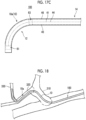
- the distal end part 10a of the medical device body 10 can be three-dimensionally (stereoscopically) bent by the operation of simultaneously pulling the fifth operation wire 45 and the second operation wire 42 (or the fourth operation wire 44) or the operation of simultaneously pulling the sixth operation wire 46 and the second operation wire 42 (or the fourth operation wire 44). Therefore, for example, as shown in FIG. 18 , the distal end part 10a of the medical device body 10 can also be inserted along each branching part (the first branching part 310 to the third branching part 330) of the body cavity (the blood vessel or the like) that branches three-dimensionally (stereoscopically) for each branching part.
- the maximum value of the tension applicable to the second operation wire 42 (or the fourth operation wire 44) by the pulling by the operation part 70 is greater than the maximum value of the tension applicable to the fifth operation wire 45 by the pulling by the operation part 70.
- the first region 12 can be primarily bent in the third direction, and the second region 14 can be primarily bent in the second direction (or the first direction).
- the maximum value of the tension applicable to the second operation wire 42 (or the fourth operation wire 44) by the pulling by the operation part 70 is greater than the maximum value of the tension applicable to the sixth operation wire 46 by the pulling by the operation part 70.
- the first region 12 can be primarily bent in the fourth direction
- the second region 14 can be primarily bent in the first direction (or the second direction).
- the operation part 70 includes, for example, a tension release mechanism (not shown) that releases a tension equal to or greater than a predetermined tension applied to the fifth operation wire 45 (or the sixth operation wire 46).
- a tension release mechanism (not shown) that releases a tension equal to or greater than a predetermined tension applied to the fifth operation wire 45 (or the sixth operation wire 46).
- the tension release mechanism is configured similarly to the tension release mechanism 86, for example.
- the medical device 100 is configured such that the maximum value of the tension applicable to the fifth operation wire 45 (or the sixth operation wire 46) (the tension when the second dial operation portion 78 rotates without engagement with respect to the second rotation member 76) is smaller than the tension applied to the second operation wire 42 when the first slider operation portion 81 is slid toward the proximal end side to the maximum.
- the present embodiment encompasses the following technical concepts.
Landscapes
- Health & Medical Sciences (AREA)
- Life Sciences & Earth Sciences (AREA)
- Engineering & Computer Science (AREA)
- Biomedical Technology (AREA)
- Pulmonology (AREA)
- Anesthesiology (AREA)
- Biophysics (AREA)
- Heart & Thoracic Surgery (AREA)
- Hematology (AREA)
- Animal Behavior & Ethology (AREA)
- General Health & Medical Sciences (AREA)
- Public Health (AREA)
- Veterinary Medicine (AREA)
- Mechanical Engineering (AREA)
- Media Introduction/Drainage Providing Device (AREA)
Abstract
Description
- The present invention relates to a medical device. Priority is claimed on
Japanese Patent Application No. 2021-211223, filed on December 24, 2021 - As a medical device capable of a bending operation of a distal end part, a type of medical device including an operation wire is known (for example, PTL 1).
- In a medical device of
PTL 1, a plurality of hollow tubes are disposed around a central lumen, and operation wires are respectively inserted into two hollow tubes facing each other with the central lumen interposed therebetween. In the medical device ofPTL 1, a distal end of the operation wire is fixed to a distal end part of the catheter. The medical device ofPTL 1 is configured to perform a pulling operation of a rear end of the operation wire. Consequently, the distal end part of the catheter can be bent by selecting and pulling the operation wire. - [PTL 1]
Japanese Unexamined Patent Application, First Publication No. 2013-48711 - However, in the medical device of
PTL 1, there is still room for improvement in terms of operability of the medical device. - The present invention has been made in view of the above-described problem and provides a medical device having a structure with more excellent operability.
- According to the present invention, there is provided a medical device including:
- an elongated medical device body;
- a first operation wire and a second operation wire, each of which extends along a longitudinal direction of the medical device body; and
- an operation part that is configured to individually and simultaneously pull the first operation wire and the second operation wire,
- in which the first operation wire and the second operation wire are disposed at opposite extreme positions in a transverse section of the medical device body,
- a distal end of the first operation wire is fixed to a distal end part of the medical device body, and
- a distal end of the second operation wire is fixed to the distal end part of the medical device body at a position on a proximal end side with respect to the distal end of the first operation wire.
- According to the present invention, it is possible to further improve operability of the medical device.
-
-
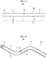
FIG. 1A is a view showing a distal end part of a medical device according to a first embodiment and is a view showing a state in which a bending operation is not performed. -
FIG. 1B is a view showing the distal end part of the medical device according to the first embodiment and is a view showing a state in which the bending operation is performed. -
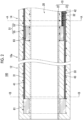
FIG. 2 is a longitudinal sectional view of a medical device body in the first embodiment. -
FIG. 3 is a transverse sectional view of the medical device body taken along line A-A ofFIG. 2 . -
FIG. 4 is a transverse sectional view of the medical device body taken along line B-B ofFIG. 2 . -
FIG. 5 is a side view showing an operation part of the medical device according to the first embodiment and a portion near the operation part. -
FIG. 6 is a plan view showing the operation part of the medical device according to the first embodiment and a portion near the operation part. -
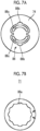
FIG. 7A is a side view of a tension release mechanism in the first embodiment. -
FIG. 7B is a side view of a first rotation member in the first embodiment. -
FIG. 7C is a view showing a state in which an engagement recessed portion and an engagement protruding portion in the first embodiment are engaged with each other. -
FIG. 7D is a view showing a state in which the engagement between the engagement protruding portion and the engagement recessed portion in the first embodiment is released. -
FIG. 8 is a schematic view in which each of (a), (b), and (c) illustrates a bending motion of the distal end part of the medical device body in the first embodiment. -
FIG. 9 is a schematic view in which (a) and (b) illustrate bending motions of the distal end part of the medical device body in the first embodiment. -
FIG. 10 is a view showing a distal end part of a medical device according to a second embodiment. -
FIG. 11 is a longitudinal sectional view of a medical device body in the second embodiment. -
FIG. 12 is a transverse sectional view of the medical device body taken along line A-A ofFIG. 11 . -
FIG. 13 is a plan view showing an operation part of the medical device according to the second embodiment and a portion near the operation part. -
FIG. 14 is a longitudinal sectional view of a medical device body in a third embodiment. -
FIG. 15 is a sectional view taken along line A-A ofFIG. 14 . -
FIG. 16 is a plan view showing an operation part of the medical device according to the third embodiment and a portion near the operation part. -
FIG. 17A is a schematic view by a plan view illustrating a bending motion of a distal end part of the medical device body in the third embodiment. -
FIG. 17B is a view illustrating a bending motion of the distal end part of the medical device body in the third embodiment and is a view as viewed in a direction of an arrow A shown inFIG. 17A . -
FIG. 17C is a view illustrating a bending motion of the distal end part of the medical device body in the third embodiment and is a view as viewed in a direction of an arrow B shown inFIG. 17A . -
FIG. 18 is a schematic view illustrating a bending motion of the distal end part of the medical device body in the third embodiment. - Hereinafter, embodiments of the present invention will be described using the drawings. In all the drawings, the same components are denoted by the same reference numerals, and descriptions thereof will be omitted as appropriate.
- Various components of a catheter according to the present embodiment are not necessarily independent entities, and a plurality of components formed as one member, one component formed of a plurality of members, a certain component as a part of another component, overlapping parts between a certain component and another component, and the like are allowed.
- The terms used in the description of the present embodiment are defined as follows unless otherwise specified.
- A distal end part is an end part (distal end) on an insertion distal end side of a
medical device 100 in each part of themedical device 100, and a proximal end part is an end part (proximal end part) on a proximal end side of themedical device 100 in each part of themedical device 100. - In addition, an axial core means a central axis along a longitudinal direction of a
medical device body 10. - A longitudinal section of the
medical device body 10 refers to a section obtained by cutting themedical device body 10 along the axial core. - A transverse section of the
medical device body 10 refers to a section obtained by cutting themedical device 100 along a plane orthogonal to the axial core. - First, a first embodiment will be described using
FIGS. 1A to 8 . InFIGS. 1A and 1B , afirst operation wire 41 to athird operation wire 43 are shown by dashed lines. In addition,FIG. 2 is a sectional view taken along line A-A ofFIG. 3 . InFIG. 5 , abody case 70a of anoperation part 70 is partially broken to show a structure inside thebody case 70a. - As shown in
FIGS. 1A ,2 , and3 , themedical device 100 according to the present embodiment includes the elongatedmedical device body 10, thefirst operation wire 41 and thesecond operation wire 42, each of which extends along the longitudinal direction of themedical device body 10, and theoperation part 70 that is configured to individually and simultaneously pull thefirst operation wire 41 and thesecond operation wire 42. - The
first operation wire 41 and thesecond operation wire 42 are disposed at opposite extreme positions in the transverse section of themedical device body 10. - A distal end of the
first operation wire 41 is fixed to adistal end part 10a of themedical device body 10, and a distal end of thesecond operation wire 42 is fixed to thedistal end part 10a of themedical device body 10 at a position on the proximal end side with respect to the distal end of thefirst operation wire 41. - Here, the opposite extreme positions mean that the
first operation wire 41 and thesecond operation wire 42 are spaced apart from each other by 160 degrees or more in a circumferential direction of themedical device body 10, and preferably, thefirst operation wire 41 and thesecond operation wire 42 are spaced apart from each other by 170 degrees or more in the circumferential direction of themedical device body 10. - According to the present embodiment, by selectively pulling the
first operation wire 41 out of thefirst operation wire 41 and thesecond operation wire 42, thedistal end part 10a of themedical device body 10 can be selectively bent in one direction (hereinafter, a first direction). Further, by simultaneously pulling thefirst operation wire 41 and thesecond operation wire 42, it is possible to primarily bend a region (hereinafter, a second region 14) on the proximal end side with respect to the distal end of thesecond operation wire 42 in a second direction while primarily bending a region (hereinafter, a first region 12) on the distal end side with respect to the distal end of thesecond operation wire 42 in the first direction, in thedistal end part 10a of themedical device body 10, as shown inFIG. 1B . In addition, by selectively pulling thesecond operation wire 42 out of thefirst operation wire 41 and thesecond operation wire 42, thedistal end part 10a of themedical device body 10 can be bent in a direction (second direction) opposite to the first direction. That is, since themedical device body 10 can be bent with a higher degree of freedom according to a branching direction of a branching part of a body cavity such as a blood vessel, the branching selectivity of themedical device 100 can be improved. Therefore, the operability of themedical device 100 can be improved. - In the case of the present embodiment, the
medical device 100 is, as an example, a catheter. More specifically, for example, themedical device 100 is an intravascular catheter used by inserting themedical device body 10 into a blood vessel. However, themedical device 100 may be, for example, a guide wire used when inserting the catheter into a body cavity. - In the case of the present embodiment, as shown in
FIGS. 1A ,2 , and3 , themedical device 100 further includes athird operation wire 43 that extends along the longitudinal direction of themedical device body 10. - The
third operation wire 43 is disposed at a position near thesecond operation wire 42 in the transverse section of themedical device body 10, and a distal end of thethird operation wire 43 is fixed to thedistal end part 10a of themedical device body 10 at a position on the distal end side with respect to the distal end of thesecond operation wire 42. - With such a configuration, by pulling the
third operation wire 43, thedistal end part 10a of themedical device body 10 can be bent in a direction substantially opposite to a direction in which thedistal end part 10a of themedical device body 10 is bent by pulling thefirst operation wire 41. - Here, being disposed at a position near the
second operation wire 42 means being positioned within 20 degrees from a position of thesecond operation wire 42 in the circumferential direction of themedical device body 10, preferably being positioned within 10 degrees from the position of thesecond operation wire 42. - In the circumferential direction of the
medical device body 10, thefirst operation wire 41, and thesecond operation wire 42 and thethird operation wire 43 are disposed at opposite extreme positions. - In addition, since the
third operation wire 43 is disposed at a position near thesecond operation wire 42 in the transverse section of themedical device body 10, thefirst operation wire 41 and thethird operation wire 43 are disposed at opposite extreme positions in the transverse section of themedical device body 10. - Here, the opposite extreme positions mean that the
first operation wire 41 and thethird operation wire 43 are spaced apart from each other by 160 degrees or more in the circumferential direction of themedical device body 10, and preferably, thefirst operation wire 41 and thethird operation wire 43 are spaced apart from each other by 170 degrees or more in the circumferential direction of themedical device body 10. - More specifically, in the case of the present embodiment, for example, as shown in
FIGS. 2 and3 , thefirst operation wire 41 and thesecond operation wire 42 are disposed at positions that are 180 degrees rotationally symmetric to each other with respect to an axial center of themedical device body 10 as a reference. In addition, thesecond operation wire 42 and thethird operation wire 43 are disposed at substantially equivalent positions in the circumferential direction of themedical device body 10 with the axial center of themedical device body 10 as a reference. Therefore, thethird operation wire 43 and thefirst operation wire 41 are disposed at positions that are 180 degrees rotationally symmetric to each other with respect to the axial center of themedical device body 10 as a reference. - In the case of the present embodiment, a direction in which the
distal end part 10a of themedical device body 10 is bent by pulling thefirst operation wire 41 and a direction in which thedistal end part 10a of themedical device body 10 is bent by pulling thethird operation wire 43 or thesecond operation wire 42 are directions opposite to each other. - The
first operation wire 41, thesecond operation wire 42, and thethird operation wire 43 are each made of a thin wire such as a metal or a resin. - Here, in the case of the present embodiment, a breaking strength of the
second operation wire 42 is greater than a breaking strength of thefirst operation wire 41. - Consequently, the
second operation wire 42 can be more strongly pulled. - More specifically, in the case of the present embodiment, the
first operation wire 41 and thesecond operation wire 42 are made of, for example, the same type of material. Meanwhile, by setting a wire diameter of thesecond operation wire 42 to a dimension larger than a wire diameter of thefirst operation wire 41, the breaking strength of thesecond operation wire 42 can be made greater than the breaking strength of thefirst operation wire 41. However, for example, by using a material having a greater breaking strength than a breaking strength of a material constituting thefirst operation wire 41 as a material constituting thesecond operation wire 42, the breaking strength of thesecond operation wire 42 can also be made greater than the breaking strength of thefirst operation wire 41. - In addition, in the case of the present embodiment, as an example, the
third operation wire 43 and thefirst operation wire 41 are made of the same type of material, and a wire diameter of thethird operation wire 43 is set to, for example, a substantially equivalent dimension to the wire diameter of thefirst operation wire 41. - For example, the wire diameter of the
third operation wire 43 and the wire diameter of thefirst operation wire 41 may be set to different dimensions from each other. Further, thethird operation wire 43 and thefirst operation wire 41 may be made of, for example, different types of materials from each other. - The wire diameter of the
first operation wire 41 and the wire diameter of thethird operation wire 43 are not particularly limited, but are preferably 10 µm or more and 60 µm or less and more preferably 20 µm or more and 50 µm or less. - The wire diameter of the
second operation wire 42 is not particularly limited, but is preferably 30 µm or more and 180 µm or less, and more preferably 60 µm or more and 150 µm or less. - Note that, as described above, it is preferable that the wire diameter of the
second operation wire 42 is larger than the wire diameter of thefirst operation wire 41. - In the case of the present embodiment, the
medical device body 10 has alumen 20 that is open at a distal end of themedical device body 10. - As shown in
FIGS. 2 and3 , themedical device body 10 has, for example, a two-layer structure including aninner layer 22 and anouter layer 23 provided around theinner layer 22 and is configured by being laminated in the order of theinner layer 22 and theouter layer 23 from an axial core side of themedical device body 10. - The
inner layer 22 is an innermost layer of themedical device body 10 and is formed, for example, in a circular tubular shape having a constant wall thickness regardless of the position in an axial direction. Theinner layer 22 is open at both ends, that is, the distal end and the proximal end of themedical device body 10. In the case of the present embodiment, thelumen 20 is defined by an inner peripheral surface of theinner layer 22. - The
inner layer 22 is made of, for example, a fluorine-based or olefin-based thermoplastic polymer resin. The fluorine-based thermoplastic polymer material is not particularly limited and can include polytetrafluoroethylene (PTFE), polyvinylidene fluoride (PVDF), and perfluoroalkoxy fluororesin (PFA), and similarly, the olefin-based polymer material can include polyethylene and the like. - The
outer layer 23 is an outermost layer of themedical device body 10. For example, the majority (more than half) of a wall thickness of themedical device body 10 is occupied by a wall thickness of theouter layer 23. Theouter layer 23 is formed, for example, in a circular tubular shape having a substantially constant wall thickness regardless of the position in the axial direction. However, an outer diameter of a distal end of a distal end part of theouter layer 23 is slightly decreased toward the distal end side, for example. - A hydrophilic coating may be formed on an outer surface layer of the
medical device body 10 as necessary. - The
lumen 20 is continuously formed from the distal end to the proximal end of themedical device body 10 and is open at the distal end and the proximal end of themedical device body 10, respectively. - As shown in
FIGS. 2 to 4 , themedical device body 10 further includes a firsthollow tube 31, a secondhollow tube 32, and a thirdhollow tube 33 that are each embedded in theouter layer 23. - The
first operation wire 41 is inserted through the firsthollow tube 31, thesecond operation wire 42 is inserted through the secondhollow tube 32, and thethird operation wire 43 is inserted through the thirdhollow tube 33. - The first
hollow tube 31, the secondhollow tube 32, and the thirdhollow tube 33 are each a sub-lumen tube, and the inner lumens of these sub-lumen tubes are sub-lumens. That is, each of the operation wires (thefirst operation wire 41, thesecond operation wire 42, and the third operation wire 43) is inserted through the sub-lumen. - Inner diameters of the first
hollow tube 31, the secondhollow tube 32, and the thirdhollow tube 33 are smaller than the inner diameter of thelumen 20. - In the case of the present embodiment, the
second operation wire 42 and the secondhollow tube 32, and thethird operation wire 43 and the thirdhollow tube 33 are disposed side by side in a radial direction of themedical device body 10. Thethird operation wire 43 and the thirdhollow tube 33 are disposed radially outward of thesecond operation wire 42 and the second hollow tube 32 (at a position away from the axial core of the medical device body 10) in themedical device body 10. - However, for example, the
second operation wire 42 and the secondhollow tube 32, and thethird operation wire 43 and the thirdhollow tube 33 may be disposed side by side in the circumferential direction of themedical device body 10. In addition, in the radial direction, a spaced distance between the axial core of themedical device body 10 and an axial core of the second operation wire 42 (or an axial core of the second hollow tube 32) may be, for example, substantially equivalent to a spaced distance between the axial core of themedical device body 10 and an axial core of the third operation wire 43 (or an axial core of the third hollow tube 33). - As materials of the first
hollow tube 31, the secondhollow tube 32, and the thirdhollow tube 33, for example, a resin material such as polytetrafluoroethylene (PTFE), polyvinylidene fluoride (PVDF), or perfluoroalkoxy fluororesin (PFA), polyethylene, or the like can be used. - As shown in
FIGS. 1A and2 , a ring-shapedfirst marker 61 made of a radiopaque metal material is embedded in thedistal end part 10a of themedical device body 10. - The
first marker 61 is disposed coaxially with thelumen 20 and around thelumen 20. - The
first marker 61 is disposed, for example, around a reinforcinglayer 51. - Further, in the
medical device body 10, a ring-shapedsecond marker 63 made of a radiopaque metal material is embedded in a part on the proximal end side with respect to a part where thefirst marker 61 is embedded. - The
second marker 63 is disposed coaxially with thelumen 20 and around thelumen 20. - The
second marker 63 is disposed, for example, around the reinforcinglayer 51. - For example, a through-hole (not shown) that penetrates a wall thickness portion of the
second marker 63 in the axial direction may be formed in thesecond marker 63. In addition, for example, a portion of thesecond marker 63 in the circumferential direction may be interrupted, and thesecond marker 63 may have a substantially C-like shape when viewed in the axial direction. - For example, the
first marker 61 and thesecond marker 63 have the same inner diameter. For example, an outer diameter of thefirst marker 61 is larger than an outer diameter of thesecond marker 63. - The distal end of the
first operation wire 41 and the distal end of the firsthollow tube 31 are fixed to a proximal end of thefirst marker 61 by, for example, soldering, welding, a mechanical coupling that generates frictional resistance, or the like (not shown). - The distal end of the
second operation wire 42 and the distal end of the secondhollow tube 32 are fixed to a proximal end of thesecond marker 63 by, for example, soldering, welding, a mechanical coupling that generates frictional resistance, or the like (not shown). - The distal end of the
third operation wire 43 and the distal end of the thirdhollow tube 33 are fixed to the proximal end of thefirst marker 61 by, for example, soldering, welding, a mechanical coupling that generates frictional resistance, or the like (not shown). - Therefore, the distal end of the
first operation wire 41 and the distal end of thethird operation wire 43 are disposed at the same position (substantially the same position) in the axial direction of themedical device body 10. - As described above, the
medical device 100 includes thefirst marker 61 that is fixed to thedistal end part 10a of themedical device body 10 and thesecond marker 63 that is fixed to thedistal end part 10a of themedical device body 10 at a position on the proximal end side with respect to thefirst marker 61, and the distal end of thefirst operation wire 41 and the distal end of thethird operation wire 43 are fixed to thefirst marker 61, and the distal end of thesecond operation wire 42 is fixed to thesecond marker 63. - In the present invention, the number of markers provided in the
medical device 100 may be, for example, two or more. - In the case of the present embodiment, in the
distal end part 10a of themedical device body 10, a region on the distal end side with respect to a distal end of thesecond marker 63 is thefirst region 12, and a region on the proximal end side with respect to the distal end of thesecond marker 63 is thesecond region 14. In thedistal end part 10a, a length of thefirst region 12 and a length of thesecond region 14 can be adjusted by setting the distance between thefirst marker 61 and thesecond marker 63 in the axial direction of themedical device body 10 to a desired distance. - In addition, the distal end part of the
first operation wire 41 is indirectly fixed to thedistal end part 10a of themedical device body 10 by being fixed to thefirst marker 61, and the distal end part of thethird operation wire 43 is indirectly fixed to thedistal end part 10a of themedical device body 10 by being fixed to thesecond marker 63. - As shown in
FIGS. 1A and2 , thefirst operation wire 41 is routed from a region on the proximal end side with respect to thesecond marker 63 to a region on the distal end side with respect to thesecond marker 63 through a portion of themedical device body 10 on a radially outer side with respect to a disposition region of thesecond marker 63. - More specifically, the first
hollow tube 31 through which thefirst operation wire 41 is inserted is also routed from the region on the proximal end side with respect to thesecond marker 63 to the region on the distal end side with respect to thesecond marker 63 through the portion of themedical device body 10 on the radially outer side with respect to the disposition region of thesecond marker 63. - However, in the present invention, a spaced distance in the radial direction between the axial core of the
medical device body 10 and the axial core of the first operation wire 41 (or the axial core of the first hollow tube 31) may be, for example, substantially equivalent to the spaced distance between the axial core of themedical device body 10 and the axial core of the second operation wire 42 (or the axial core of the second hollow tube 32). - Similarly, the
third operation wire 43 is routed from the region on the proximal end side with respect to thesecond marker 63 to the region on the distal end side with respect to thesecond marker 63 through the portion of themedical device body 10 on the radially outer side with respect to the disposition region of thesecond marker 63. - More specifically, the third
hollow tube 33 through which thethird operation wire 43 is inserted is also routed from the region on the proximal end side with respect to thesecond marker 63 to the region on the distal end side with respect to thesecond marker 63 through the portion of themedical device body 10 on the radially outer side with respect to the disposition region of thesecond marker 63. - However, in the present invention, the spaced distance in the radial direction between the axial core of the
medical device body 10 and the axial core of the third operation wire 43 (or the axial core of the third hollow tube 33) may be, for example, substantially equivalent to the spaced distance between the axial core of themedical device body 10 and the axial core of the second operation wire 42 (or the axial core of the second hollow tube 32). - Here, in the case of the present embodiment, the
medical device body 10 includes the reinforcinglayer 51. A bending stiffness of the reinforcinglayer 51 on the proximal end side with respect to thesecond marker 63 is greater than a bending stiffness of the reinforcinglayer 51 on the distal end side with respect to thesecond marker 63. A bending stiffness of themedical device body 10 on the proximal end side with respect to thesecond marker 63 is greater than a bending stiffness of themedical device body 10 on the distal end side with respect to thesecond marker 63. - More specifically, as shown in
FIGS. 2 and3 , the reinforcinglayer 51 includes, for example, ablade layer 53 embedded in theouter layer 23 and a windingwire 55 embedded in theouter layer 23. Each of theblade layer 53 and the windingwire 55 extends from the distal end side to aproximal end part 10b of themedical device body 10. However, as shown inFIG. 2 , a distal end of theblade layer 53 is disposed, for example, at a position substantially equivalent to a position of the distal end of thesecond marker 63 in the axial direction. Meanwhile, a distal end of the windingwire 55 is disposed, for example, at a position substantially equivalent to a position of a distal end of thefirst marker 61 in the axial direction. - Consequently, in the
medical device body 10, the region on the proximal end side with respect to thesecond marker 63 is reinforced by theblade layer 53 and the windingwire 55, and the region on the distal end side with respect to thesecond marker 63 is reinforced by the windingwire 55. Therefore, the bending stiffness of themedical device body 10 on the proximal end side with respect to thesecond marker 63 is greater than the bending stiffness of themedical device body 10 on the distal end side with respect to thesecond marker 63. - The
blade layer 53 is formed by braiding a plurality of wires. Theblade layer 53 is disposed, for example, around theinner layer 22. - The first
hollow tube 31, the secondhollow tube 32, and the thirdhollow tube 33 are disposed, for example, radially outward of the reinforcing layer 51 (at a position away from the axial core of the medical device body 10) in themedical device body 10. - A material of the wire constituting the
blade layer 53 is preferably, for example, a metal material such as stainless steel or tungsten, but may be a resin material. - The winding
wire 55 is wound around themedical device body 10 radially outward of the reinforcinglayer 51, the firsthollow tube 31, the secondhollow tube 32, and the thirdhollow tube 33. - A material of the wire constituting the winding
wire 55 is preferably, for example, a metal material such as stainless steel or tungsten, but may be a resin material. - In the present invention, the distal end of the
blade layer 53 may be disposed, for example, at a position substantially equivalent to the position of the distal end of the first marker 61 (the position of the distal end of the winding wire 55). In this case, for example, it is preferable that theblade layer 53 in thefirst region 12 is composed of a fewer number of wires than the number of wires in thesecond region 14, or that an opening width of the mesh of theblade layer 53 in thefirst region 12 is larger than an opening width of the mesh of theblade layer 53 in thesecond region 14. By doing so, a configuration can be employed in which the bending stiffness of themedical device body 10 on the proximal end side with respect to thesecond marker 63 is greater than the bending stiffness of themedical device body 10 on the distal end side with respect to thesecond marker 63. - In addition, in the present invention, the reinforcing
layer 51 may include, for example, a coil layer (not shown) formed by winding a wire a plurality of times, instead of theblade layer 53. - As shown in
FIGS. 5 and6 , in the case of the present embodiment, themedical device 100 includes ahub 91 provided at the proximal end part of themedical device body 10. - The
hub 91 includes acoupling portion 93 for inserting an injector (syringe) (not shown) into a proximal end of thehub 91. A screw groove is formed on an outer periphery of thecoupling portion 93 such that the syringe can be attachably and detachably fixed. - The
hub 91 includes twoblade portions 92 that face each other with the axial core of thehub 91 interposed therebetween and that are provided on an outer periphery of thehub 91. - The proximal end part of the
medical device body 10 is inserted into and fixed to a distal end part of thehub 91. Consequently, thelumen 20 inside themedical device body 10 and an internal space of thehub 91 communicate with each other. - By rotating the
blade portions 92 about the axial core of thehub 91, it is possible to perform a torque operation of rotating the entiremedical device body 10 about the axis. - The
body case 70a of theoperation part 70, which will be described below, is connected and fixed to the distal end side of thehub 91. - As described above, the
medical device 100 includes theoperation part 70 for performing the bending operation of thedistal end part 10a of themedical device body 10. With respect to theoperation part 70, an operation of selectively pulling one of thefirst operation wire 41 or thethird operation wire 43, and an operation of individually and simultaneously pulling thefirst operation wire 41 and thesecond operation wire 42 are possible. - As shown in
FIGS. 5 and6 , theoperation part 70 includes, for example, thebody case 70a and afirst rotation member 71 that is pivotally supported to be rotatable with respect to thebody case 70a. - The
first rotation member 71 is, for example, a pulley. - Here, in the present specification, a certain member being rotatable is not limited to an aspect in which the member is rotatable by 360 degrees or more, but also includes an aspect in which the member is only swingable in a predetermined angular range of less than 360 degrees.
- More specifically, a first
dial operation portion 74 having a disc-like shape or the like is engaged with thefirst rotation member 71 coaxially with thefirst rotation member 71. Since the firstdial operation portion 74 is pivotally supported to be rotatable with respect to thebody case 70a, thefirst rotation member 71 is indirectly and pivotally supported to be rotatable with respect to thebody case 70a. - The
proximal end part 10b of themedical device body 10 is led to the proximal end side of thebody case 70a through the inside of thebody case 70a, and is inserted into and fixed to the distal end part of thehub 91. - A rotary shaft of the first
dial operation portion 74 extends in a direction orthogonal to an axial core direction of themedical device body 10 in thebody case 70a. - As shown in
FIG. 6 , at least a portion of the firstdial operation portion 74 is exposed to the outside of thebody case 70a, and an operator who operates themedical device 100 can operate the firstdial operation portion 74 from the outside of thebody case 70a. - Further, the
operation part 70 includes, for example, a firstslider operation portion 81 that is fixed to thebody case 70a to be slidable in the axial direction. - A slide hole (not shown) that extends in the axial direction is formed in the
body case 70a, and the firstslider operation portion 81 is guided by the slide hole and is slidable in the axial direction relative to thebody case 70a. - As shown in
FIG. 6 , at least a portion of the firstslider operation portion 81 is exposed to the outside of thebody case 70a via the slide hole, and the operator who operates themedical device 100 can perform an operation of sliding the firstslider operation portion 81 toward the proximal end side or the distal end side from the outside of thebody case 70a. - As shown in
FIG. 5 , each of thefirst operation wire 41, thesecond operation wire 42, and thethird operation wire 43 is led out from themedical device body 10 in thebody case 70a. - A proximal end part of the
first operation wire 41 is, for example, wound around thefirst rotation member 71 by one and a half turns, and a proximal end of thefirst operation wire 41 is fixed to thefirst rotation member 71. - In addition, a proximal end part of the
third operation wire 43 is, for example, wound around thefirst rotation member 71 by one and a half turns, and a proximal end of thethird operation wire 43 is fixed to thefirst rotation member 71. - A winding direction of the
first operation wire 41 and a winding direction of thethird operation wire 43 with respect to thefirst rotation member 71 are directions opposite to each other. - In a case where the
first rotation member 71 that is engaged with the firstdial operation portion 74 is rotated in one direction by a rotation operation with respect to the firstdial operation portion 74, thefirst operation wire 41 out of thefirst operation wire 41 and thethird operation wire 43 is selectively pulled toward the proximal end side. - In addition, in a case where the
first rotation member 71 is rotated in a direction opposite to the above-described one direction by the rotation operation with respect to the firstdial operation portion 74, thethird operation wire 43 out of thefirst operation wire 41 and thethird operation wire 43 is selectively pulled toward the proximal end side. - A proximal end of the
second operation wire 42 is fixed to, for example, the firstslider operation portion 81. - In a case where the first
slider operation portion 81 is moved toward the proximal end side relative to thebody case 70a in the axial direction through a sliding operation with respect to the firstslider operation portion 81, thesecond operation wire 42 is pulled toward the proximal end side. - Therefore, by operating either the first
dial operation portion 74 or the firstslider operation portion 81, an operation of individually pulling either the first operation wire 41 (or the third operation wire 43) or thesecond operation wire 42 is possible. - In addition, by operating the first
dial operation portion 74 and operating the firstslider operation portion 81 in parallel, an operation of simultaneously pulling the first operation wire 41 (or the third operation wire 43) and thesecond operation wire 42 is possible. - Here, simultaneously pulling the
first operation wire 41 and thesecond operation wire 42 means that there is a timing at which both thefirst operation wire 41 and thesecond operation wire 42 are pulled together. This does not necessarily mean that the starting timing of pulling both thefirst operation wire 41 and thesecond operation wire 42 is the same, nor does it mean that the timing of finishing pulling both thefirst operation wire 41 and thesecond operation wire 42 is the same. - Further, the
operation part 70 includes, for example, a tension release mechanism 86 (refer toFIGS. 7A to 7D ) that releases a tension equal to or greater than a predetermined tension applied to thefirst operation wire 41. - The
tension release mechanism 86 includes, for example, an engagement recessedportion 86a formed in thefirst rotation member 71 and anengagement protruding portion 86b formed on the firstdial operation portion 74. - As shown in
FIG. 7B , an opening portion penetrating thefirst rotation member 71 in a thickness direction is formed in a central part of thefirst rotation member 71. In thefirst rotation member 71, a peripheral edge part of the opening portion includes, for example, a plurality of recesses and protrusions in which the recesses and the protrusions are alternately disposed along a circumferential direction of thefirst rotation member 71, and a plurality of the engagement recessedportions 86a are formed by the recesses and the protrusions. - As shown in
FIG. 7A , in the case of the present embodiment, a pair ofengagement protruding portions 86b are formed on the firstdial operation portion 74. Each of the pair ofengagement protruding portions 86b is formed in a shape of protruding toward a radially outer side. The pair ofengagement protruding portions 86b are disposed at positions that are 180 degrees rotationally symmetric to each other with respect to an axial center of the firstdial operation portion 74 as a reference. In addition, a pair ofslit portions 86c penetrating the firstdial operation portion 74 in a thickness direction is formed in the firstdial operation portion 74. The pair ofslit portions 86c are disposed at positions that are 180 degrees rotationally symmetric to each other with respect to the axial center of the firstdial operation portion 74 as a reference. When viewed in the axial direction of the firstdial operation portion 74, each slitportion 86c forms, for example, an arc shape protruding toward the radially outer side. Eachslit portion 86c is formed, whereby the firstdial operation portion 74 is elastically deformable toward a radially inner side. - As shown in
FIG. 7D , eachengagement protruding portion 86b is engaged with one engagement recessedportion 86a of the plurality of engagement recessedportions 86a. - Next, motions will be described.
- First, in a case where the operation of selectively pulling the
first operation wire 41 toward the proximal end side is performed, a tension is applied to thefirst operation wire 41, and as shown in (a) ofFIG. 8 , thedistal end part 10a of themedical device body 10 is bent toward a side (hereinafter, the first direction) of the firsthollow tube 31 through which thefirst operation wire 41 is inserted, with the axial core of themedical device body 10 as a reference. - In addition, in a case where the operation of selectively pulling the
third operation wire 43 toward the proximal end side is performed, a tension is applied to thethird operation wire 43, and as shown in (b) ofFIG. 8 ,, thedistal end part 10a of themedical device body 10 is bent toward a side (hereinafter, the second direction) of the thirdhollow tube 33 through which thethird operation wire 43 is inserted, with the axial core of themedical device body 10 as a reference. Here, for example, the first direction and the second direction are directions included in the same plane (hereinafter, a first virtual plane) and are directions opposite to each other. - Further, in a case where the operation of simultaneously pulling both the
first operation wire 41 and thesecond operation wire 42 is performed, as shown in (c) ofFIG. 8 , thefirst region 12 is primarily bent in the first direction, and thesecond region 14 is primarily bent in the second direction. That is, in a case where a tension is applied to thesecond operation wire 42, thedistal end part 10a of themedical device body 10 is bent toward a side (thirdhollow tube 33 side) of the secondhollow tube 32 through which thesecond operation wire 42 is inserted, with the axial core of themedical device body 10 as a reference in a region on the proximal end side with respect to thefirst region 12. Therefore, a combined motion occurs in which a motion of primarily bending thesecond region 14 in the second direction by pulling thesecond operation wire 42 and a motion of primarily bending thefirst region 12 in the first direction by pulling thefirst operation wire 41. - The operation of pulling the
second operation wire 42 may be performed alone. In this case, thesecond region 14 is primarily bent in the second direction. - As described above, according to the present embodiment, the operation of selectively bending the
distal end part 10a of themedical device body 10 in the first direction, the operation of selectively bending thedistal end part 10a of themedical device body 10 in the second direction, and the operation of primarily bending thefirst region 12 in the first direction and primarily bending thesecond region 14 in the second direction are possible. Therefore, the branching selectivity of themedical device 100 at each branching part of the body cavity (the blood vessel or the like) is improved. - More specifically, for example, when inserting the
distal end part 10a into each branching part (branchingparts 310 to 330 shown inFIG. 9 ) of the body cavity (the blood vessel or the like), thedistal end part 10a is bent in the second direction by the operation of pulling thethird operation wire 43 at a timing at which the distal end of thedistal end part 10a approaches the second branchingpart 320 that branches from the first branchingpart 310, as shown in (a) ofFIG. 9 . Consequently, thedistal end part 10a can be inserted into the second branchingpart 320. Subsequently, at a timing at which the distal end of thedistal end part 10a approaches the third branchingpart 330 that branches from the second branchingpart 320, the pulling with respect to thethird operation wire 43 is released, and thedistal end part 10a (primarily the second region 14) is bent in the second direction by the operation of pulling thesecond operation wire 42, thereby entering a backed-up state. More specifically, even when attempting to perform a torque rotation operation of rotating themedical device body 10 around the axis in a state in which thesecond operation wire 42 is pulled toward the proximal end side, thedistal end part 10a tends to maintain a state in which the second hollow tube 32 (second operation wire 42) side is located most inwardly (in-course) of the curvature with the axial core of themedical device body 10 as a reference, so that the rotation by the rotation operation is less likely to be transmitted to themedical device body 10. In other words, themedical device body 10 is restrained from rotating around the axis, thereby entering a backed-up state. - Then, by pulling the
first operation wire 41 while maintaining a state in which thesecond operation wire 42 is pulled from this state, thedistal end part 10a is bent in a substantially S-like shape and inserted into the third branchingpart 330 as shown in (b) ofFIG. 9 . - Here, in the case of the present embodiment, as described above, the breaking strength of the
second operation wire 42 is greater than the breaking strength of thefirst operation wire 41. - Consequently, when simultaneously pulling the
first operation wire 41 and thesecond operation wire 42, thefirst region 12 can be primarily bent in the first direction while maintaining a state in which thesecond region 14 is primarily bent in the second direction. - Further, in the case of the present embodiment, as described above, the
medical device body 10 includes the reinforcinglayer 51. The bending stiffness of the reinforcinglayer 51 on the proximal end side with respect to thesecond marker 63 is greater than the bending stiffness of the reinforcinglayer 51 on the distal end side with respect to thesecond marker 63. The bending stiffness of themedical device body 10 on the proximal end side with respect to thesecond marker 63 is greater than the bending stiffness of themedical device body 10 on the distal end side with respect to thesecond marker 63. - As a result, more reliably, the
first region 12 can be primarily bent in the first direction while maintaining a state in which thesecond region 14 is primarily bent in the second direction when simultaneously pulling thefirst operation wire 41 and thesecond operation wire 42. - Here, in the case of the present embodiment, the maximum value of the tension applicable to the
second operation wire 42 by the pulling by theoperation part 70 is greater than the maximum value of the tension applicable to thefirst operation wire 41 by the pulling by theoperation part 70. - Consequently, the backup capability of the
first operation wire 41 with respect to thesecond operation wire 42 and thethird operation wire 43 can be sufficiently ensured. Therefore, more reliably, thefirst region 12 can be primarily bent in the first direction while maintaining a state in which thesecond region 14 is primarily bent in the second direction when simultaneously pulling thefirst operation wire 41 and thesecond operation wire 42. - More specifically, in the case of the present embodiment, when attempting to pull the
first operation wire 41 with a tension equal to or higher than a certain level, the engagement between the engagement recessedportion 86a and theengagement protruding portion 86b is temporarily released, and the firstdial operation portion 74 is configured to rotate without engagement with respect to thefirst rotation member 71. That is, the tension when the firstdial operation portion 74 rotates without engagement with respect to thefirst rotation member 71 is the maximum value of the tension applicable to thefirst operation wire 41. - In more detail, as described above, since the distal end of the
first operation wire 41 is fixed to thefirst marker 61, when the force exerted by theoperation part 70 to pull thefirst operation wire 41 toward the proximal end side increases, the force to pull back thefirst operation wire 41 toward the distal end side also increases. Then, when the force to pull back thefirst operation wire 41 toward the distal end side is equal to or higher than a certain level, thefirst rotation member 71 is elastically deformed toward the radially inner side, and the engagement between the engagement recessedportion 86a and theengagement protruding portion 86b is temporarily released. Consequently, the firstdial operation portion 74 rotates without engagement with respect to the first rotation member 71 (the rotation of the firstdial operation portion 74 is not transmitted to the first rotation member 71). - When the force to pull the
first operation wire 41 toward the proximal end side and the force to pull back thefirst operation wire 41 toward the distal end side reach an equilibrium state, the engagement recessedportion 86a and theengagement protruding portion 86b are engaged with each other, thereby consequently maintaining the engagement state between thefirst rotation member 71 and the firstdial operation portion 74. - Here, in the case of the present embodiment, the
medical device 100 is configured such that the maximum value of the tension applicable to the first operation wire 41 (the tension when the firstdial operation portion 74 rotates without engagement with respect to the first rotation member 71) is smaller than the tension applied to thesecond operation wire 42 when the firstslider operation portion 81 is slid toward the proximal end side to the maximum. Therefore, it is possible to restrain the tension applied to thefirst operation wire 41 by the pulling by theoperation part 70 from exceeding the maximum value of the tension applicable to thesecond operation wire 42 by the pulling by theoperation part 70. - In the case of the present embodiment, the maximum value of the tension applicable to the
first operation wire 41 by the pulling by theoperation part 70 can be set as appropriate, for example, based on the depth dimension (radial dimension) of the engagement recessedportion 86a, the depth dimension or the length dimension (circumferential dimension) of theslit portion 86c, the elastic force (spring force) of thefirst rotation member 71, and the like. - In addition, the maximum value of the tension applicable to the
second operation wire 42 by the pulling by theoperation part 70 can be set as appropriate, for example, based on the maximum stroke of the first slider operation portion 81 (the axial dimension of the slide hole). - Similarly, the maximum value of the tension applicable to the
second operation wire 42 by the pulling by theoperation part 70 is greater than the maximum value of the tension applicable to thethird operation wire 43 by the pulling by theoperation part 70. - More specifically, the
medical device 100 is configured such that the maximum value of the tension applicable to the third operation wire 43 (the tension when the firstdial operation portion 74 rotates without engagement with respect to the first rotation member 71) is smaller than the tension applied to thesecond operation wire 42 when the firstslider operation portion 81 is slid toward the proximal end side to the maximum. - Next, a second embodiment will be described using
FIGS. 10 to 13 .FIG. 11 is a sectional view taken along line A-A ofFIG. 12 . - The
medical device 100 according to the present embodiment is different from themedical device 100 according to the above-described first embodiment in the points to be described below and is configured similarly to themedical device 100 according to the above-described first embodiment in other points. - In the case of the present embodiment, the
medical device 100 further includes afourth operation wire 44 that extends along the longitudinal direction of themedical device body 10. - As shown in
FIGS. 11 and12 , thefourth operation wire 44 is disposed at a position near thefirst operation wire 41 in the transverse section of themedical device body 10, and a distal end of thefourth operation wire 44 is fixed to thedistal end part 10a of themedical device body 10 at a position on the proximal end side with respect to the distal end of thethird operation wire 43. A breaking strength of thefourth operation wire 44 is greater than the breaking strength of thethird operation wire 43. - With such a configuration, by simultaneously pulling the
third operation wire 43 and thefourth operation wire 44, as shown inFIG. 10 , thefirst region 12 can be primarily bent in the second direction, and thesecond region 14 can be primarily bent in the first direction. That is, since an operation similar to the bending operation performed by the operation of simultaneously pulling thefirst operation wire 41 and the second operation wire 42 (here, motions that are 180 degrees rotationally symmetric to each other with respect to the axial core of themedical device body 10 as a reference) can be achieved even with an operation of simultaneously pulling thethird operation wire 43 and thefourth operation wire 44, a need to perform the torque rotation operation of rotating themedical device body 10 around the axis prior to the bending operation can be eliminated, or the rotation amount in the torque rotation operation can be reduced. Therefore, the operability of themedical device 100 can be improved. - In
FIG. 11 , thefirst operation wire 41 to thefourth operation wire 44 are shown by dashed lines. - In the case of the present embodiment, as shown in
FIGS. 11 and12 , thethird operation wire 43 and thefourth operation wire 44 are disposed at opposite extreme positions in the transverse section of themedical device body 10. - Here, the opposite extreme positions mean that the
third operation wire 43 and thefourth operation wire 44 are spaced apart from each other by 160 degrees or more in the circumferential direction of themedical device body 10, and preferably, thethird operation wire 43 and thefourth operation wire 44 are spaced apart from each other by 170 degrees or more in the circumferential direction of themedical device body 10. - More specifically, in the case of the present embodiment, for example, the
fourth operation wire 44 and thefirst operation wire 41 are disposed at substantially equivalent positions in the circumferential direction of themedical device body 10 with the axial center of themedical device body 10 as a reference. Therefore, thefourth operation wire 44 is disposed at a position that is 180 degrees rotationally symmetric to thesecond operation wire 42 and thethird operation wire 43 with respect to the axial center of themedical device body 10 as a reference. - In the case of the present embodiment, a direction in which the
distal end part 10a of themedical device body 10 is bent by pulling thefourth operation wire 44 and a direction in which thedistal end part 10a of themedical device body 10 is bent by pulling the third operation wire 43 (or the second operation wire 42) are directions opposite to each other. - As shown in
FIGS. 10 and11 , in the case of the present embodiment, themedical device 100 includes a fourthhollow tube 34 that is embedded in theouter layer 23, and thefourth operation wire 44 is inserted through the fourthhollow tube 34. - The fourth
hollow tube 34 is also a sub-lumen tube, and the inner lumen of the sub-lumen tube is a sub-lumen, similar to the firsthollow tube 31 to the thirdhollow tube 33. That is, thefourth operation wire 44 is inserted through the sub-lumen. - An inner diameter of the fourth
hollow tube 34 is smaller than the inner diameter of thelumen 20. - The
fourth operation wire 44 is made of a thin wire such as a metal or a resin, similar to thefirst operation wire 41 to thethird operation wire 43. - A wire diameter of the
fourth operation wire 44 is set to be, for example, substantially equivalent to the wire diameter of thesecond operation wire 42. Therefore, the wire diameter of thefourth operation wire 44 is larger than the wire diameter of thefirst operation wire 41 and the wire diameter of thethird operation wire 43. - The wire diameter of the
fourth operation wire 44 is not particularly limited, but is, for example, preferably 30 µm or more and 180 µm or less and more preferably 60 µm or more and 150 µm or less. - The distal end of the
fourth operation wire 44 and the distal end of the fourthhollow tube 34 are fixed to the proximal end of thesecond marker 63. Therefore, the distal end of thesecond operation wire 42 and the distal end of thefourth operation wire 44 are fixed at equivalent positions in the longitudinal direction of themedical device body 10. The distal end of thefirst operation wire 41 and the distal end of thethird operation wire 43 are fixed at positions on the distal end side with respect to the positions where the distal end of thesecond operation wire 42 and the distal end of thefourth operation wire 44 are fixed. - In the case of the present embodiment, in addition to the above-described operations, an operation of individually pulling the
fourth operation wire 44 toward the proximal end side and an operation of simultaneously pulling thethird operation wire 43 and thefourth operation wire 44 toward the proximal end side can be performed with respect to theoperation part 70. - Here, simultaneously pulling the
third operation wire 43 and thefourth operation wire 44 means that there is a timing at which both thethird operation wire 43 and thefourth operation wire 44 are pulled together. This does not necessarily mean that the starting timing of pulling both thethird operation wire 43 and thefourth operation wire 44 is the same, nor does it mean that the timing of finishing pulling both thethird operation wire 43 and thefourth operation wire 44 is the same. - More specifically, as shown in
FIG. 13 , theoperation part 70 further includes a secondslider operation portion 84 that is fixed to thebody case 70a to be slidable in the axial direction. - The second
slider operation portion 84 is configured similarly to the firstslider operation portion 81, for example. Therefore, a slide hole (not shown) for guiding the secondslider operation portion 84 along the axial direction is formed in thebody case 70a. The firstslider operation portion 81 and the secondslider operation portion 84 are disposed at positions that are 180 degrees rotationally symmetric to each other with respect to the axial core of themedical device body 10 as a reference. - As shown in
FIG. 13 , at least a portion of the secondslider operation portion 84 is exposed to the outside of thebody case 70a, and the operator who operates themedical device 100 can perform an operation of sliding the secondslider operation portion 84 from the outside of thebody case 70a. - A proximal end of the
fourth operation wire 44 is fixed to, for example, the secondslider operation portion 84. - In a case where the second
slider operation portion 84 is slid toward the proximal end side relative to thebody case 70a in the axial direction through the operation with respect to the secondslider operation portion 84, thefourth operation wire 44 is pulled toward the proximal end side. - Therefore, by operating the first
dial operation portion 74 and operating the secondslider operation portion 84 in parallel, an operation of simultaneously pulling thethird operation wire 43 and thefourth operation wire 44 is possible. - Here, in the case of the present embodiment, the maximum value of the tension applicable to the
fourth operation wire 44 by the pulling by theoperation part 70 is greater than the maximum value of the tension applicable to the third operation wire 43 (first operation wire 41) by the pulling by theoperation part 70. - Consequently, by simultaneously pulling the
third operation wire 43 and thefourth operation wire 44, more reliably, thefirst region 12 can be primarily bent in the second direction, and thesecond region 14 can be primarily bent in the first direction. - More specifically, a configuration is employed in which a tension required to rotate the first
dial operation portion 74 without engagement is smaller than the tension applied to thefourth operation wire 44 when the secondslider operation portion 84 is slid toward the proximal end side to the maximum. As a result, it is possible to restrain the tension applied to thethird operation wire 43 by the pulling by theoperation part 70 from exceeding the maximum value of the tension applicable to thefourth operation wire 44 by the pulling by theoperation part 70. - Next, a third embodiment will be described using
FIGS. 14 to 18 . - The
medical device 100 according to the present embodiment is different from themedical device 100 according to the above-described first and second embodiments in the points to be described below and is configured similarly to themedical device 100 according to the above-described first and second embodiments in other points. - As shown in
FIGS. 14 and15 , in the case of the present embodiment, themedical device 100 further includes afifth operation wire 45 that extends along the longitudinal direction of themedical device body 10. - The
fifth operation wire 45 is disposed in a region between the disposition region of thefirst operation wire 41 and thefourth operation wire 44 and the disposition region of thesecond operation wire 42 and thethird operation wire 43 in the circumferential direction of the transverse section of themedical device body 10. - A distal end of the
fifth operation wire 45 is fixed to thedistal end part 10a of themedical device body 10 at a position on the distal end side with respect to the distal end of thesecond operation wire 42 and the distal end of thefourth operation wire 44. - With such a configuration, by pulling the
fifth operation wire 45 toward the proximal end side, thedistal end part 10a of themedical device body 10 can be bent in a direction different from the first direction and the second direction, so that the branching selectivity of themedical device 100 at each branching part of the body cavity (the blood vessel or the like) can be further improved. - Further, when inserting the
distal end part 10a into each branching part of the body cavity (the blood vessel or the like), a need to perform the torque rotation operation of rotating themedical device body 10 around the axis prior to the bending operation can be eliminated, or the rotation amount in the torque rotation operation can be reduced. Therefore, the operability of themedical device 100 can be improved. - Here, in the case of the present embodiment, the
fifth operation wire 45 is preferably disposed at a position that is at least approximately 45 degrees different from the disposition region of thefirst operation wire 41 and the fourth operation wire 44 (or the disposition region of thesecond operation wire 42 and the third operation wire 43) and more preferably disposed at a position that is at approximately 90 degrees different, in the circumferential direction. - The distal end of the
fifth operation wire 45 and the distal end of the first operation wire 41 (and the third operation wire 43) are fixed at equivalent positions in the longitudinal direction of themedical device body 10. - As shown in
FIG. 15 , as an example, thefifth operation wire 45, and thefirst operation wire 41 and thethird operation wire 43 are disposed at positions different from each other by approximately 90 degrees in the circumferential direction of themedical device body 10. Similarly, as an example, thefifth operation wire 45, and thethird operation wire 43 and thefourth operation wire 44 are disposed at positions different from each other by approximately 90 degrees in the circumferential direction of themedical device body 10. - As shown in
FIG. 15 , in the case of the present embodiment, themedical device 100 further includes, for example, asixth operation wire 46 that extends along the longitudinal direction of themedical device body 10. - The distal end of the
fifth operation wire 45 and a distal end of thesixth operation wire 46 are fixed at equivalent positions in the longitudinal direction of themedical device body 10. Therefore, the distal end of thesixth operation wire 46 and the distal end of the first operation wire 41 (and the third operation wire 43) are fixed at equivalent positions in the longitudinal direction of themedical device body 10. - The
sixth operation wire 46 and thefifth operation wire 45 are disposed at positions that are 180 degrees rotationally symmetric to each other with respect to the axial center of themedical device body 10 as a reference. Therefore, thesixth operation wire 46 is disposed in a region between the disposition region of thefirst operation wire 41 and thefourth operation wire 44 and the disposition region of thesecond operation wire 42 and thethird operation wire 43 in the circumferential direction of the transverse section of themedical device body 10. More specifically, thesixth operation wire 46, and thefirst operation wire 41 and thethird operation wire 43 are spaced apart from each other by approximately 90 degrees in the circumferential direction of themedical device body 10, and thesixth operation wire 46, and thethird operation wire 43 and thefourth operation wire 44 are spaced apart from each other by approximately 90 degrees in the circumferential direction of themedical device body 10. - In the case of the present embodiment, a direction in which the
distal end part 10a of themedical device body 10 is bent by pulling the fifth operation wire 45 (hereinafter, a third direction) and a direction in which thedistal end part 10a of themedical device body 10 is bent by pulling the sixth operation wire 46 (hereinafter, a fourth direction) are directions opposite to each other. - As shown in
FIG. 15 , in the case of the present embodiment, themedical device 100 includes a fifthhollow tube 35 and a sixthhollow tube 36 that are embedded in theouter layer 23. Thefifth operation wire 45 is inserted through the fifthhollow tube 35, and thesixth operation wire 46 is inserted through the sixthhollow tube 36. - The fifth
hollow tube 35 and the sixthhollow tube 36 are sub-lumen tubes, and the inner lumens of the sub-lumen tubes are sub-lumens, similar to the firsthollow tube 31 to the thirdhollow tube 33. - An inner diameter of the fifth
hollow tube 35 and an inner diameter of the sixthhollow tube 36 are smaller than the inner diameter of thelumen 20. - The
fifth operation wire 45 and thesixth operation wire 46 are made of thin wires such as metals or resins, similar to thefirst operation wire 41 to thethird operation wire 43. - The breaking strengths of the
second operation wire 42 and thefourth operation wire 44 are larger than the breaking strengths of thefifth operation wire 45 and thesixth operation wire 46. More specifically, in the case of the present embodiment, thefirst operation wire 41 to thesixth operation wire 46 are made of the same type of material. However, thefirst operation wire 41 to thesixth operation wire 46 are made of, for example, different types of materials from each other. - Meanwhile, by setting the wire diameters of the
second operation wire 42 and thefourth operation wire 44 to dimensions larger than the wire diameters of thefifth operation wire 45 and thesixth operation wire 46, the breaking strengths of thesecond operation wire 42 and thefourth operation wire 44 can be made greater than the breaking strengths of thefifth operation wire 45 and thesixth operation wire 46. However, for example, by using a material having a greater breaking strength than breaking strengths of materials constituting thefifth operation wire 45 and thesixth operation wire 46 as a material constituting thefourth operation wire 44, the breaking strength of thefourth operation wire 44 can also be made greater than the breaking strengths of thefifth operation wire 45 and thesixth operation wire 46. - The wire diameter of the
fifth operation wire 45 and the wire diameter of thesixth operation wire 46 are not particularly limited, but are preferably 10 µm or more and 60 µm or less and more preferably 20 µm or more and 50 µm or less. - As shown in
FIG. 14 , the distal end of the fifthhollow tube 35 and the distal end of thefifth operation wire 45 are fixed to the proximal end of thefirst marker 61. Similarly, the distal end of the sixthhollow tube 36 and the distal end of thesixth operation wire 46 are fixed to the proximal end of thefirst marker 61. - As described above, in the case of the present embodiment, the number of operation wires whose distal ends are fixed at positions on the distal end side with respect to the positions where the distal end of the
second operation wire 42 and the distal end of thefourth operation wire 44 are fixed is equal to or greater than the number of operation wires whose distal ends are fixed at equivalent positions to thesecond operation wire 42 and thefourth operation wire 44. - Here, the equivalent position means that the spaced distance between the distal ends of the respective operation wires in the axial direction of the
medical device body 10 is smaller than the outer diameter of themedical device body 10. In addition, as in the present embodiment, in a case where the distal ends of the respective operation wires are fixed to a common marker (thefirst marker 61 or the second marker 63), the axial dimension of the marker may be larger than the outer diameter of themedical device body 10, but is preferably smaller than the outer diameter of themedical device body 10. - In the case of the present embodiment, in addition to the above-described operations, an operation of selectively pulling either the
fifth operation wire 45 or thesixth operation wire 46 toward the proximal end side, an operation of individually and simultaneously pulling thefifth operation wire 45 and the second operation wire 42 (or the fourth operation wire 44), and an operation of individually and simultaneously pulling thesixth operation wire 46 and the second operation wire 42 (or the fourth operation wire 44) are possible with respect to theoperation part 70. - More specifically, as shown in
FIG. 16 , theoperation part 70 includes asecond rotation member 76 that is pivotally supported to be rotatable with respect to thebody case 70a, and a seconddial operation portion 78 that is fixed to thesecond rotation member 76. - The
second rotation member 76 is configured similarly to thefirst rotation member 71, for example. The seconddial operation portion 78 is configured similarly to the firstdial operation portion 74, for example. - In the example shown in
FIG. 16 , the firstdial operation portion 74 and the seconddial operation portion 78 are disposed to overlap each other in a direction orthogonal to their plate surfaces, and the rotary shaft of the firstdial operation portion 74 and a rotary shaft of the seconddial operation portion 78 are coaxially disposed. - However, the rotary shaft of the first
dial operation portion 74 and the rotary shaft of the seconddial operation portion 78 need not be coaxially disposed. For example, the firstdial operation portion 74 and the seconddial operation portion 78 may be disposed at positions different from each other in the axial direction of themedical device body 10. - In the case of the present embodiment, a proximal end part of the
fifth operation wire 45 is, for example, wound around thesecond rotation member 76 by one and a half turns, and a proximal end of thefifth operation wire 45 is fixed to thesecond rotation member 76. - In addition, a proximal end part of the
sixth operation wire 46 is, for example, wound around thesecond rotation member 76 by one and a half turns, and a proximal end of thesixth operation wire 46 is fixed to thesecond rotation member 76. - A winding direction of the
fifth operation wire 45 and a winding direction of thesixth operation wire 46 with respect to thesecond rotation member 76 are directions opposite to each other. - In a case where the
second rotation member 76 that is engaged with the seconddial operation portion 78 is rotated in one direction by a rotation operation with respect to the seconddial operation portion 78, thefifth operation wire 45 out of thefifth operation wire 45 and thesixth operation wire 46 is selectively pulled toward the proximal end side. Then, thedistal end part 10a of themedical device body 10 is bent toward a side of the fifthhollow tube 35 through which thefifth operation wire 45 is inserted, with the axial core of themedical device body 10 as a reference. Here, as described above, a plane including the direction (first direction) in which thedistal end part 10a is bent by pulling thefirst operation wire 41 and the direction (second direction) in which thedistal end part 10a is bent by pulling thesecond operation wire 42 is referred to as the first virtual plane. The direction (referred to as the third direction) in which thedistal end part 10a is bent by pulling thefifth operation wire 45 is, for example, a direction included in a second virtual plane orthogonal to the first virtual plane. - In addition, in a case where the
second rotation member 76 is rotated in the opposite direction to the above-described one direction by the rotation operation with respect to the seconddial operation portion 78, thesixth operation wire 46 out of thefifth operation wire 45 and thesixth operation wire 46 is selectively pulled toward the proximal end side. Then, thedistal end part 10a of themedical device body 10 is bent toward a side of the sixthhollow tube 36 through which thesixth operation wire 46 is inserted, with the axial core of themedical device body 10 as a reference. That is, thedistal end part 10a of themedical device body 10 is bent in the opposite direction (fourth direction) to the third direction with the axial core of themedical device body 10 as a reference. The fourth direction is also a direction included in the second virtual plane. - Further, in a case where an operation of pulling both the
fifth operation wire 45 and the second operation wire 42 (or the fourth operation wire 44) is performed, as shown inFIGS. 17A to 17C , thefirst region 12 is primarily bent in the third direction, and thesecond region 14 is primarily bent in the second direction (or the first direction). That is, in the first and second embodiments, the bending of thedistal end part 10a is two-dimensional bending in the above-described first virtual plane, but in the case of the present embodiment, it is possible to achieve a so-called three-dimensional (stereoscopic) bending of thedistal end part 10a by combining the bending in the first virtual plane and the bending in the second virtual plane. - In addition, in a case where an operation of pulling both the
sixth operation wire 46 and the second operation wire 42 (or the fourth operation wire 44) is performed, thefirst region 12 is primarily bent in the fourth direction, and thesecond region 14 is primarily bent in the second direction (or the first direction). That is, in this case as well, thedistal end part 10a can be three-dimensionally (stereoscopically) bent. - As described above, according to the present embodiment, the
distal end part 10a of themedical device body 10 can be three-dimensionally (stereoscopically) bent by the operation of simultaneously pulling thefifth operation wire 45 and the second operation wire 42 (or the fourth operation wire 44) or the operation of simultaneously pulling thesixth operation wire 46 and the second operation wire 42 (or the fourth operation wire 44). Therefore, for example, as shown inFIG. 18 , thedistal end part 10a of themedical device body 10 can also be inserted along each branching part (the first branchingpart 310 to the third branching part 330) of the body cavity (the blood vessel or the like) that branches three-dimensionally (stereoscopically) for each branching part. - Here, in the case of the present embodiment, the maximum value of the tension applicable to the second operation wire 42 (or the fourth operation wire 44) by the pulling by the
operation part 70 is greater than the maximum value of the tension applicable to thefifth operation wire 45 by the pulling by theoperation part 70. - This allows for sufficient backup, and by simultaneously pulling the
fifth operation wire 45 and the second operation wire 42 (or the fourth operation wire 44), more reliably, thefirst region 12 can be primarily bent in the third direction, and thesecond region 14 can be primarily bent in the second direction (or the first direction). - Similarly, in the case of the present embodiment, the maximum value of the tension applicable to the second operation wire 42 (or the fourth operation wire 44) by the pulling by the
operation part 70 is greater than the maximum value of the tension applicable to thesixth operation wire 46 by the pulling by theoperation part 70. - This allows for sufficient backup, and by simultaneously pulling the
sixth operation wire 46 and the second operation wire 42 (or the fourth operation wire 44), more reliably, thefirst region 12 can be primarily bent in the fourth direction, and thesecond region 14 can be primarily bent in the first direction (or the second direction). - More specifically, the
operation part 70 includes, for example, a tension release mechanism (not shown) that releases a tension equal to or greater than a predetermined tension applied to the fifth operation wire 45 (or the sixth operation wire 46). - The tension release mechanism is configured similarly to the
tension release mechanism 86, for example. - Therefore, the
medical device 100 is configured such that the maximum value of the tension applicable to the fifth operation wire 45 (or the sixth operation wire 46) (the tension when the seconddial operation portion 78 rotates without engagement with respect to the second rotation member 76) is smaller than the tension applied to thesecond operation wire 42 when the firstslider operation portion 81 is slid toward the proximal end side to the maximum. - Each embodiment has been described with reference to the drawings; however, these are illustrative examples of the present invention, and various configurations other than those described above can also be employed.
- In addition, the respective embodiments described above can be appropriately combined within a range that does not depart from the gist of the present invention.
- The present embodiment encompasses the following technical concepts.
- (1) A medical device including:
- an elongated medical device body;
- a first operation wire and a second operation wire, each of which extends along a longitudinal direction of the medical device body; and
- an operation part that is configured to individually and simultaneously pull the first operation wire and the second operation wire,
- in which the first operation wire and the second operation wire are disposed at opposite extreme positions in a transverse section of the medical device body,
- a distal end of the first operation wire is fixed to a distal end part of the medical device body, and
- a distal end of the second operation wire is fixed to the distal end part of the medical device body at a position on a proximal end side with respect to the distal end of the first operation wire.
- (2) The medical device according to (1),
in which a breaking strength of the second operation wire is greater than a breaking strength of the first operation wire. - (3) The medical device according to (1) or (2),
in which a maximum value of a tension applicable to the second operation wire by the pulling by the operation part is greater than a maximum value of a tension applicable to the first operation wire by the pulling by the operation part. - (4) The medical device according to any one of (1) to (3), further comprising:
- a third operation wire that extends along the longitudinal direction of the medical device body,
- in which the third operation wire is disposed at a position near the second operation wire in the transverse section of the medical device body, and
- a distal end of the third operation wire is fixed to the distal end part of the medical device body at a position on a distal end side with respect to the distal end of the second operation wire.
- (5) The medical device according to (4), further comprising:
- a fourth operation wire that extends along the longitudinal direction of the medical device body,
- in which the fourth operation wire is disposed at a position near the first operation wire in the transverse section of the medical device body,
- a distal end of the fourth operation wire is fixed to the distal end part of the medical device body at a position on the proximal end side with respect to the distal end of the third operation wire, and
- a breaking strength of the fourth operation wire is greater than a breaking strength of the third operation wire.
- (6) The medical device according to (5), further comprising:
- a fifth operation wire that extends along the longitudinal direction of the medical device body,
- in which the fifth operation wire is disposed in a region between a disposition region of the first operation wire and the fourth operation wire and a disposition region of the second operation wire and the third operation wire in a circumferential direction of the transverse section of the medical device body, and
- a distal end of the fifth operation wire is fixed to the distal end part of the medical device body at a position on the distal end side with respect to the distal end of the second operation wire and the distal end of the fourth operation wire.
- (7) The medical device according to (6),
- in which the distal end of the second operation wire and the distal end of the fourth operation wire are fixed at equivalent positions in the longitudinal direction of the medical device body, and
- the number of operation wires whose distal ends are fixed at positions on the distal end side with respect to the positions where the distal end of the second operation wire and the distal end of the fourth operation wire are fixed is equal to or greater than the number of operation wires whose distal ends are fixed at the equivalent positions to the second operation wire and the fourth operation wire.
- (8) The medical device according to any one of (4) to (7), further comprising:
- a first marker that is fixed to the distal end part of the medical device body; and
- a second marker that is fixed to the distal end part of the medical device body at a position on the proximal end side with respect to the first marker,
- in which the distal end of the first operation wire and the distal end of the third operation wire are fixed to the first marker, and
- the distal end of the second operation wire is fixed to the second marker.
- (9) The medical device according to (8),
- in which the medical device body includes a reinforcing layer,
- a bending stiffness of the reinforcing layer on the proximal end side with respect to the second marker is greater than a bending stiffness of the reinforcing layer on the distal end side with respect to the second marker, and
- a bending stiffness of the medical device body on the proximal end side with respect to the second marker is greater than a bending stiffness of the medical device body on the distal end side with respect to the second marker.
- (10) The medical device according to any one of (1) to (9),
- in which the medical device is a catheter, and
- the medical device body has a lumen that is open at a distal end of the medical device body.
-
- 10: medical device body
- 10a: distal end part
- 10b: proximal end part
- 12: first region
- 14: second region
- 20: lumen
- 22: inner layer
- 23: outer layer
- 31: first hollow tube
- 32: second hollow tube
- 33: third hollow tube
- 34: fourth hollow tube
- 35: fifth hollow tube
- 36: sixth hollow tube
- 41: first operation wire
- 42: second operation wire
- 43: third operation wire
- 44: fourth operation wire
- 45: fifth operation wire
- 46: sixth operation wire
- 51: reinforcing layer
- 53: blade layer
- 55: winding wire
- 61: first marker
- 63: second marker
- 70: operation part
- 70a: body case
- 71: first rotation member
- 74: first dial operation portion
- 76: second rotation member
- 78: second dial operation portion
- 81: first slider operation portion
- 84: second slider operation portion
- 86: tension release mechanism
- 86a: engagement recessed portion
- 86b: engagement protruding portion
- 86c: slit portion
- 91: hub
- 92: blade portion
- 93: coupling portion
- 96: gate portion
- 100: medical device
- 310: first branching part
- 320: second branching part
- 330: third branching part
Claims (10)
- A medical device comprising:an elongated medical device body;a first operation wire and a second operation wire, each of which extends along a longitudinal direction of the medical device body; andan operation part that is configured to individually and simultaneously pull the first operation wire and the second operation wire,wherein the first operation wire and the second operation wire are disposed at opposite extreme positions in a transverse section of the medical device body,a distal end of the first operation wire is fixed to a distal end part of the medical device body, anda distal end of the second operation wire is fixed to the distal end part of the medical device body at a position on a proximal end side with respect to the distal end of the first operation wire.
- The medical device according to Claim 1,
wherein a breaking strength of the second operation wire is greater than a breaking strength of the first operation wire. - The medical device according to Claim 1,
wherein a maximum value of a tension applicable to the second operation wire by the pulling by the operation part is greater than a maximum value of a tension applicable to the first operation wire by the pulling by the operation part. - The medical device according to Claim 1, further comprising:a third operation wire that extends along the longitudinal direction of the medical device body,wherein the third operation wire is disposed at a position near the second operation wire in the transverse section of the medical device body, anda distal end of the third operation wire is fixed to the distal end part of the medical device body at a position on a distal end side with respect to the distal end of the second operation wire.
- The medical device according to Claim 4, further comprising:a fourth operation wire that extends along the longitudinal direction of the medical device body,wherein the fourth operation wire is disposed at a position near the first operation wire in the transverse section of the medical device body,a distal end of the fourth operation wire is fixed to the distal end part of the medical device body at a position on the proximal end side with respect to the distal end of the third operation wire, anda breaking strength of the fourth operation wire is greater than a breaking strength of the third operation wire.
- The medical device according to Claim 5, further comprising:a fifth operation wire that extends along the longitudinal direction of the medical device body,wherein the fifth operation wire is disposed in a region between a disposition region of the first operation wire and the fourth operation wire and a disposition region of the second operation wire and the third operation wire in a circumferential direction of the transverse section of the medical device body, anda distal end of the fifth operation wire is fixed to the distal end part of the medical device body at a position on the distal end side with respect to the distal end of the second operation wire and the distal end of the fourth operation wire.
- The medical device according to Claim 6,wherein the distal end of the second operation wire and the distal end of the fourth operation wire are fixed at equivalent positions in the longitudinal direction of the medical device body, andthe number of operation wires whose distal ends are fixed at positions on the distal end side with respect to the positions where the distal end of the second operation wire and the distal end of the fourth operation wire are fixed is equal to or greater than the number of operation wires whose distal ends are fixed at the equivalent positions to the second operation wire and the fourth operation wire.
- The medical device according to Claim 4, further comprising:a first marker that is fixed to the distal end part of the medical device body; anda second marker that is fixed to the distal end part of the medical device body at a position on the proximal end side with respect to the first marker,wherein the distal end of the first operation wire and the distal end of the third operation wire are fixed to the first marker, andthe distal end of the second operation wire is fixed to the second marker.
- The medical device according to Claim 8,wherein the medical device body includes a reinforcing layer,a bending stiffness of the reinforcing layer on the proximal end side with respect to the second marker is greater than a bending stiffness of the reinforcing layer on the distal end side with respect to the second marker, anda bending stiffness of the medical device body on the proximal end side with respect to the second marker is greater than a bending stiffness of the medical device body on the distal end side with respect to the second marker.
- The medical device according to Claim 1,wherein the medical device is a catheter, andthe medical device body has a lumen that is open at a distal end of the medical device body.
Applications Claiming Priority (2)
| Application Number | Priority Date | Filing Date | Title |
|---|---|---|---|
| JP2021211223A JP7827454B2 (en) | 2021-12-24 | 2021-12-24 | medical devices |
| PCT/JP2022/046061 WO2023120329A1 (en) | 2021-12-24 | 2022-12-14 | Medical device |
Publications (2)
| Publication Number | Publication Date |
|---|---|
| EP4454694A1 true EP4454694A1 (en) | 2024-10-30 |
| EP4454694A4 EP4454694A4 (en) | 2025-07-16 |
Family
ID=86902535
Family Applications (1)
| Application Number | Title | Priority Date | Filing Date |
|---|---|---|---|
| EP22911037.4A Pending EP4454694A4 (en) | 2021-12-24 | 2022-12-14 | Medical device |
Country Status (5)
| Country | Link |
|---|---|
| US (1) | US20250128026A1 (en) |
| EP (1) | EP4454694A4 (en) |
| JP (1) | JP7827454B2 (en) |
| CN (1) | CN118401275A (en) |
| WO (1) | WO2023120329A1 (en) |
Family Cites Families (6)
| Publication number | Priority date | Publication date | Assignee | Title |
|---|---|---|---|---|
| JP4897077B1 (en) | 2010-09-28 | 2012-03-14 | 日本ライフライン株式会社 | catheter |
| JP2013048711A (en) | 2011-08-31 | 2013-03-14 | Japan Lifeline Co Ltd | Deflectable tip catheter |
| JP7027917B2 (en) | 2018-01-31 | 2022-03-02 | 住友ベークライト株式会社 | catheter |
| JP7660914B2 (en) | 2019-08-02 | 2025-04-14 | ビザラメド, インコーポレイテッド | Steerable Sheath |
| JP2021078849A (en) | 2019-11-20 | 2021-05-27 | 朝日インテック株式会社 | catheter |
| WO2021257810A1 (en) * | 2020-06-19 | 2021-12-23 | Deinde Medical Corp. | Steerable catheters and related methods |
-
2021
- 2021-12-24 JP JP2021211223A patent/JP7827454B2/en active Active
-
2022
- 2022-12-14 CN CN202280083112.0A patent/CN118401275A/en active Pending
- 2022-12-14 EP EP22911037.4A patent/EP4454694A4/en active Pending
- 2022-12-14 US US18/717,609 patent/US20250128026A1/en active Pending
- 2022-12-14 WO PCT/JP2022/046061 patent/WO2023120329A1/en not_active Ceased
Also Published As
| Publication number | Publication date |
|---|---|
| WO2023120329A1 (en) | 2023-06-29 |
| JP7827454B2 (en) | 2026-03-10 |
| EP4454694A4 (en) | 2025-07-16 |
| JP2023095379A (en) | 2023-07-06 |
| CN118401275A (en) | 2024-07-26 |
| US20250128026A1 (en) | 2025-04-24 |
Similar Documents
| Publication | Publication Date | Title |
|---|---|---|
| KR20230093530A (en) | Catheter and method for manufacturing catheter | |
| EP2937110B1 (en) | Medical device | |
| JP5747449B2 (en) | catheter | |
| EP3412329B1 (en) | Catheter | |
| JP2013180156A (en) | Medical equipment | |
| US20220054802A1 (en) | Guide wire | |
| JP6089864B2 (en) | Medical device and method for manufacturing medical device | |
| JP7555174B2 (en) | Medical Devices | |
| US11571549B2 (en) | Medical device | |
| WO2017154749A1 (en) | Medical device | |
| WO2018008272A1 (en) | Catheter | |
| US20250128026A1 (en) | Medical device | |
| JP2012061070A (en) | Catheter | |
| JP7027917B2 (en) | catheter | |
| WO2019026995A1 (en) | Medical device | |
| JP2019024919A (en) | catheter | |
| JP2014018391A (en) | Catheter | |
| KR102459494B1 (en) | Medical Equipment | |
| JP2023094820A (en) | catheter | |
| JP7462378B2 (en) | Medical equipment | |
| JP2018083006A (en) | Medical apparatus | |
| JP2024027763A (en) | Medical long body |
Legal Events
| Date | Code | Title | Description |
|---|---|---|---|
| STAA | Information on the status of an ep patent application or granted ep patent |
Free format text: STATUS: THE INTERNATIONAL PUBLICATION HAS BEEN MADE |
|
| PUAI | Public reference made under article 153(3) epc to a published international application that has entered the european phase |
Free format text: ORIGINAL CODE: 0009012 |
|
| STAA | Information on the status of an ep patent application or granted ep patent |
Free format text: STATUS: REQUEST FOR EXAMINATION WAS MADE |
|
| 17P | Request for examination filed |
Effective date: 20240606 |
|
| AK | Designated contracting states |
Kind code of ref document: A1 Designated state(s): AL AT BE BG CH CY CZ DE DK EE ES FI FR GB GR HR HU IE IS IT LI LT LU LV MC ME MK MT NL NO PL PT RO RS SE SI SK SM TR |
|
| DAV | Request for validation of the european patent (deleted) | ||
| DAX | Request for extension of the european patent (deleted) | ||
| A4 | Supplementary search report drawn up and despatched |
Effective date: 20250616 |
|
| RIC1 | Information provided on ipc code assigned before grant |
Ipc: A61M 25/00 20060101AFI20250610BHEP Ipc: A61M 25/092 20060101ALI20250610BHEP Ipc: A61M 25/098 20060101ALI20250610BHEP Ipc: A61M 25/01 20060101ALI20250610BHEP |
|
| STAA | Information on the status of an ep patent application or granted ep patent |
Free format text: STATUS: EXAMINATION IS IN PROGRESS |
|
| 17Q | First examination report despatched |
Effective date: 20260320 |