WO2019026995A1 - Medical device - Google Patents
Medical device Download PDFInfo
- Publication number
- WO2019026995A1 WO2019026995A1 PCT/JP2018/029023 JP2018029023W WO2019026995A1 WO 2019026995 A1 WO2019026995 A1 WO 2019026995A1 JP 2018029023 W JP2018029023 W JP 2018029023W WO 2019026995 A1 WO2019026995 A1 WO 2019026995A1
- Authority
- WO
- WIPO (PCT)
- Prior art keywords
- operation line
- medical device
- device body
- rotating member
- line
- Prior art date
Links
- 238000005452 bending Methods 0.000 claims description 256
- 229920005989 resin Polymers 0.000 claims description 83
- 239000011347 resin Substances 0.000 claims description 83
- 238000004804 winding Methods 0.000 description 50
- 239000000463 material Substances 0.000 description 30
- 239000003550 marker Substances 0.000 description 21
- 210000004204 blood vessel Anatomy 0.000 description 10
- -1 polytetrafluoroethylene Polymers 0.000 description 10
- 238000010586 diagram Methods 0.000 description 9
- 239000002033 PVDF binder Substances 0.000 description 8
- 229920001343 polytetrafluoroethylene Polymers 0.000 description 8
- 239000004810 polytetrafluoroethylene Substances 0.000 description 8
- 229920002981 polyvinylidene fluoride Polymers 0.000 description 8
- 229910000679 solder Inorganic materials 0.000 description 8
- 238000006243 chemical reaction Methods 0.000 description 6
- 239000002184 metal Substances 0.000 description 6
- 229910052751 metal Inorganic materials 0.000 description 6
- 239000007769 metal material Substances 0.000 description 6
- 230000002093 peripheral effect Effects 0.000 description 6
- YCKRFDGAMUMZLT-UHFFFAOYSA-N Fluorine atom Chemical compound [F] YCKRFDGAMUMZLT-UHFFFAOYSA-N 0.000 description 4
- 229920001774 Perfluoroether Polymers 0.000 description 4
- 239000004952 Polyamide Substances 0.000 description 4
- 239000004698 Polyethylene Substances 0.000 description 4
- 239000004642 Polyimide Substances 0.000 description 4
- 239000004743 Polypropylene Substances 0.000 description 4
- 239000005038 ethylene vinyl acetate Substances 0.000 description 4
- 229910052731 fluorine Inorganic materials 0.000 description 4
- 239000011737 fluorine Substances 0.000 description 4
- 229920001200 poly(ethylene-vinyl acetate) Polymers 0.000 description 4
- 229920002647 polyamide Polymers 0.000 description 4
- 229920000573 polyethylene Polymers 0.000 description 4
- 229920000139 polyethylene terephthalate Polymers 0.000 description 4
- 239000005020 polyethylene terephthalate Substances 0.000 description 4
- 229920001721 polyimide Polymers 0.000 description 4
- 229920001155 polypropylene Polymers 0.000 description 4
- 229910001220 stainless steel Inorganic materials 0.000 description 4
- 239000010935 stainless steel Substances 0.000 description 4
- WFKWXMTUELFFGS-UHFFFAOYSA-N tungsten Chemical compound [W] WFKWXMTUELFFGS-UHFFFAOYSA-N 0.000 description 4
- 229910052721 tungsten Inorganic materials 0.000 description 4
- 239000010937 tungsten Substances 0.000 description 4
- 239000004677 Nylon Substances 0.000 description 2
- 238000009954 braiding Methods 0.000 description 2
- DQXBYHZEEUGOBF-UHFFFAOYSA-N but-3-enoic acid;ethene Chemical compound C=C.OC(=O)CC=C DQXBYHZEEUGOBF-UHFFFAOYSA-N 0.000 description 2
- 229920001971 elastomer Polymers 0.000 description 2
- 239000000806 elastomer Substances 0.000 description 2
- 239000000203 mixture Substances 0.000 description 2
- 229920001778 nylon Polymers 0.000 description 2
- 229920002312 polyamide-imide Polymers 0.000 description 2
- 239000004814 polyurethane Substances 0.000 description 2
- 239000004800 polyvinyl chloride Substances 0.000 description 2
- 238000004904 shortening Methods 0.000 description 2
- 238000009751 slip forming Methods 0.000 description 2
- 238000005516 engineering process Methods 0.000 description 1
- 238000003780 insertion Methods 0.000 description 1
- 230000037431 insertion Effects 0.000 description 1
- 238000000034 method Methods 0.000 description 1
Images


Classifications
-
- A—HUMAN NECESSITIES
- A61—MEDICAL OR VETERINARY SCIENCE; HYGIENE
- A61B—DIAGNOSIS; SURGERY; IDENTIFICATION
- A61B5/00—Measuring for diagnostic purposes; Identification of persons
- A61B5/68—Arrangements of detecting, measuring or recording means, e.g. sensors, in relation to patient
- A61B5/6846—Arrangements of detecting, measuring or recording means, e.g. sensors, in relation to patient specially adapted to be brought in contact with an internal body part, i.e. invasive
- A61B5/6847—Arrangements of detecting, measuring or recording means, e.g. sensors, in relation to patient specially adapted to be brought in contact with an internal body part, i.e. invasive mounted on an invasive device
-
- A—HUMAN NECESSITIES
- A61—MEDICAL OR VETERINARY SCIENCE; HYGIENE
- A61M—DEVICES FOR INTRODUCING MEDIA INTO, OR ONTO, THE BODY; DEVICES FOR TRANSDUCING BODY MEDIA OR FOR TAKING MEDIA FROM THE BODY; DEVICES FOR PRODUCING OR ENDING SLEEP OR STUPOR
- A61M25/00—Catheters; Hollow probes
- A61M25/01—Introducing, guiding, advancing, emplacing or holding catheters
- A61M25/0105—Steering means as part of the catheter or advancing means; Markers for positioning
- A61M25/0133—Tip steering devices
- A61M25/0136—Handles therefor
-
- A—HUMAN NECESSITIES
- A61—MEDICAL OR VETERINARY SCIENCE; HYGIENE
- A61M—DEVICES FOR INTRODUCING MEDIA INTO, OR ONTO, THE BODY; DEVICES FOR TRANSDUCING BODY MEDIA OR FOR TAKING MEDIA FROM THE BODY; DEVICES FOR PRODUCING OR ENDING SLEEP OR STUPOR
- A61M25/00—Catheters; Hollow probes
- A61M25/01—Introducing, guiding, advancing, emplacing or holding catheters
- A61M25/0105—Steering means as part of the catheter or advancing means; Markers for positioning
- A61M25/0133—Tip steering devices
- A61M25/0147—Tip steering devices with movable mechanical means, e.g. pull wires
- A61M2025/015—Details of the distal fixation of the movable mechanical means
Abstract
The present invention provides a medical device or the like comprising an elongated medical device body, a first manipulation wire and a second manipulation wire respectively inserted along the axial direction of the medical device body, and a flexural manipulation part for flexing a distal end of the medical device body through pulling exerted by the first manipulation wire and the second manipulation wire. At an intermediate part and proximal end part with respect to the axial direction of the medical device body, the first manipulation wire and the second manipulation wire extend separately from and parallel with each other in the circumferential direction of the medical device body. At a distal end part with respect to the axial direction of the medical device body, the first manipulation wire and the second manipulation wire gradually curve and converge toward each other toward the distal end side along the circumferential direction of the medical device body.
Description
本発明は、医療機器に関する。
本願は、2017年8月2日に日本に出願された特願2017-150210号、2018年1月31日に日本に出願された特願2018-015534号、2018年1月31日に日本に出願された特願2018-015535号に基づき優先権を主張し、その内容をここに援用する。 The present invention relates to medical devices.
Priority is claimed on Japanese Patent Application No. 2017-150210, filed on Aug. 2, 2017, Japanese Patent Application No. 2018-015534, filed on Jan. 31, 2018, on Jan. 31, 2018. Priority is claimed based on Japanese Patent Application No. 2018-015535, the content of which is incorporated herein by reference.
先端部の屈曲操作が可能なカテーテル等の長尺な医療機器としては、操作線を有するタイプのものが知られている(例えば、特許文献1)。
As a long medical device such as a catheter or the like capable of bending the distal end, a type having a control line is known (for example, Patent Document 1).
特許文献1のカテーテルにおいては、中央のルーメンの周囲に複数の中空管が配置されており、中央のルーメンを介して対向する2本の中空管の内部にそれぞれ操作線が挿通されている。同文献のカテーテルにおいては、操作線の先端は、当該カテーテルの先端部に固定されている。同文献のカテーテルは、操作線の後端を牽引操作することが可能に構成されている。これにより、操作線を選択して牽引することでカテーテルの先端部を屈曲させることができるようになっている。
In the catheter of Patent Document 1, a plurality of hollow tubes are disposed around a central lumen, and operation wires are respectively inserted into two opposing hollow tubes through the central lumen. . In the catheter of the same document, the tip of the operation line is fixed to the tip of the catheter. The catheter of the same document is configured to be able to pull the rear end of the operation line. Thereby, the distal end portion of the catheter can be bent by selecting and pulling the operation line.
しかしながら、特許文献1のカテーテルでは、湾曲した血管等の体腔を通過した後で更に先端部を屈曲させる際には、湾曲の内側方向には容易に屈曲させることができるが、外側方向に屈曲させにくい。
なぜなら、湾曲のアウトコース側に位置する操作線を牽引してカテーテルの先端を外側方向に屈曲させようとすると、牽引される操作線の経路が短くなる方向へと、湾曲した血管内でカテーテルが当該カテーテルの軸周りに回転してしまうためである。 However, in the catheter ofPatent Document 1, when the distal end is further bent after passing through a body cavity such as a curved blood vessel, it can be easily bent in the inward direction of the curve, but is bent in the outward direction. Hateful.
This is because, when pulling the operation line located on the out-course side of the curve and trying to bend the tip of the catheter outward, the catheter in the curved blood vessel is in the direction of shortening the path of the pulled operation line. This is because the catheter is rotated about its axis.
なぜなら、湾曲のアウトコース側に位置する操作線を牽引してカテーテルの先端を外側方向に屈曲させようとすると、牽引される操作線の経路が短くなる方向へと、湾曲した血管内でカテーテルが当該カテーテルの軸周りに回転してしまうためである。 However, in the catheter of
This is because, when pulling the operation line located on the out-course side of the curve and trying to bend the tip of the catheter outward, the catheter in the curved blood vessel is in the direction of shortening the path of the pulled operation line. This is because the catheter is rotated about its axis.
本発明は、上記の課題に鑑みてなされたものであり、より確実に先端部を所望の向きに屈曲させることが可能な構造のカテーテル等の医療機器を提供するものである。
The present invention has been made in view of the above-described problems, and provides a medical device such as a catheter having a structure capable of bending the distal end portion in a desired direction more reliably.
また、カテーテル等の医療機器においては、多様なニーズに応じた操作性が求められており、この観点で特許文献1の技術にはなお改善の余地がある。
Moreover, in medical devices such as catheters, operability in accordance with various needs is required, and from this viewpoint, the technology of Patent Document 1 still has room for improvement.
本発明は、上記の課題に鑑みてなされたものであり、多様なニーズに応じた操作性を好適に実現することが可能な構造のカテーテル等の医療機器を提供するものである。
The present invention has been made in view of the above problems, and provides a medical device such as a catheter having a structure capable of suitably realizing operability in accordance with various needs.
本発明は、長尺な医療機器本体と、
前記医療機器本体の軸方向に沿ってそれぞれ挿通されている第1操作線及び第2操作線と、
前記第1操作線及び前記第2操作線の牽引により前記医療機器本体の先端部の屈曲操作を行うための屈曲操作部と、
を備え、
前記医療機器本体の軸方向における中間部及び基端部では、前記第1操作線と前記第2操作線とが前記医療機器本体の周方向において互いに離間して並列に延在しており、
前記医療機器本体の軸方向における先端部では、前記第1操作線と前記第2操作線とが先端側に向けて徐々に前記医療機器本体の周方向において互いに近づくように湾曲し合流している医療機器を提供するものである。 The present invention relates to a long medical device body,
A first operation line and a second operation line respectively inserted along the axial direction of the medical device body;
A bending operation unit for bending an end portion of the medical device body by pulling the first operation line and the second operation line;
Equipped with
The first operation line and the second operation line are spaced apart from each other in the circumferential direction of the medical device body and extend in parallel at an intermediate portion and a base end portion in the axial direction of the medical device body,
At the distal end portion in the axial direction of the medical device body, the first operation line and the second operation line are curved and joined so as to gradually approach each other in the circumferential direction of the medical device body toward the distal end side It provides medical equipment.
また、本発明は、長尺な医療機器本体と、
前記医療機器本体の軸方向に沿ってそれぞれ挿通されている第1操作線及び第2操作線と、
前記第1操作線及び前記第2操作線の牽引により前記医療機器本体の先端部の屈曲操作を行うための屈曲操作部と、
を備え、
前記屈曲操作部は、
回転可能に軸支されている回転部材であって、前記第1操作線の基端部と前記第2操作線の基端部とが固定されている回転部材と、
前記回転部材を前記第1操作線及び前記第2操作線を牽引する牽引方向、及び、前記牽引方向に対する反対方向に移動させる移動機構と、
ユーザの操作を受け付けて動作する操作受付部と、
を備え、
前記操作受付部の動力が前記移動機構を介して前記回転部材に伝達されることで、前記回転部材が前記牽引方向及び前記反対方向に移動する医療機器を提供するものである。 The present invention also relates to a long medical device body,
A first operation line and a second operation line respectively inserted along the axial direction of the medical device body;
A bending operation unit for bending an end portion of the medical device body by pulling the first operation line and the second operation line;
Equipped with
The bending operation unit is
A rotating member rotatably supported, wherein the base end of the first operation line and the base end of the second operation line are fixed;
A pulling direction in which the rotating member is pulled along the first operation line and the second operation line, and a moving mechanism moving the rotating member in a direction opposite to the pulling direction;
An operation receiving unit that operates by receiving user operations;
Equipped with
The motive power of the said operation reception part is transmitted to the said rotation member via the said moving mechanism, and the said rotation member provides the medical instrument which moves to the said pulling direction and the said opposite direction.
本発明によれば、より確実に先端部を所望の向きに屈曲させることが可能である。また、本発明によれば、多様なニーズに応じた操作性を好適に実現することが可能である。
According to the present invention, it is possible to bend the tip in a desired direction more reliably. Moreover, according to the present invention, it is possible to preferably realize operability according to various needs.
以下、本発明の実施形態について、図面を用いて説明する。なお、すべての図面において、同様の構成要素には同一の符号を付し、適宜に説明を省略する。
本実施形態に係る医療機器の各種の構成要素は、個々に独立した存在である必要はなく、複数の構成要素が一個の部材として形成されていること、一つの構成要素が複数の部材で形成されていること、ある構成要素が他の構成要素の一部であること、ある構成要素の一部と他の構成要素の一部とが重複していること、等を許容する。 Hereinafter, embodiments of the present invention will be described using the drawings. In all the drawings, the same components are denoted by the same reference numerals, and the description will not be repeated.
The various components of the medical device according to the present embodiment do not have to be individually independent, and a plurality of components are formed as one member, and one component is formed of a plurality of members. Allow one component to be part of another component, overlap between part of one component and part of another component, etc.
本発明の実施形態を説明する際に用いられる用語は、特段の断りがない限り、以下のとおり定義される。
実施形態の説明において、先端部および基端部という用語を使用する場合がある。先端部とは、医療機器の各部において、医療機器の挿入先端側の端(遠位端)を含む所定の長さ領域をいう。また基端部とは、医療機器の各部において、医療機器の基端側の端(近位端)を含む所定の長さ領域をいう。
また、軸心とは、医療機器本体の長手方向に沿った中心軸を意味する。
医療機器の縦断面とは、医療機器を軸心に沿って切断した断面をいう。
医療機器の横断面とは、医療機器を軸心に対して直交する平面で切断した断面をいう。 Terms used in describing the embodiments of the present invention are defined as follows unless otherwise noted.
The terms tip and proximal may be used in the description of the embodiments. The tip portion refers to a predetermined length region including the end (distal end) on the insertion tip side of the medical device in each part of the medical device. Further, the proximal end refers to a predetermined length region including the proximal end (proximal end) of the medical device in each part of the medical device.
Moreover, an axial center means the central axis along the longitudinal direction of the medical device body.
The longitudinal cross section of a medical device means the cross section which cut the medical device along the axial center.
The cross section of a medical device means the cross section which cut the medical device by the plane which intersects perpendicularly to the axis.
〔第1-1実施形態〕
先ず、図1から図8(b)を用いて第1-1実施形態を説明する。
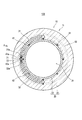
なお、図1は図2のA-A線に沿った断面図である。
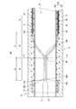
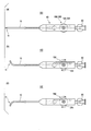
図5(a)及び図5(b)は医療機器本体10の先端部11を図4の矢印A方向に視たときの屈曲動作を説明するための模式図であり、図5(a)は屈曲前の状態を示し、図5(b)は屈曲した状態を示す。
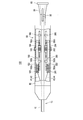
図7においては、部分的に屈曲操作部80の筐体86を破断して筐体86の内部の構造を示している。
図8(a)、図8(b)においては、医療機器本体10の長手方向における途中部分を破断して省略している。図8(a)及び図8(b)に示す医療機器本体10において、省略部分よりも基端側の部分と先端側の部分とでは、医療機器本体10の軸周りにおける回転位相が90度異なっている。 Embodiment 1-1
First, the first embodiment will be described with reference to FIGS. 1 to 8B.
FIG. 1 is a cross-sectional view taken along the line AA of FIG.
5 (a) and 5 (b) are schematic diagrams for explaining the bending operation when thedistal end portion 11 of the medical device body 10 is viewed in the direction of arrow A in FIG. 4, and FIG. The state before bending is shown, and FIG. 5 (b) shows the state of bending.
In FIG. 7, thehousing 86 of the bending operation unit 80 is partially broken to show the internal structure of the housing 86.
In FIG. 8A and FIG. 8B, a midway portion in the longitudinal direction of the medical devicemain body 10 is broken and omitted. In the medical device body 10 shown in FIGS. 8A and 8B, the rotational phase around the axis of the medical device body 10 differs by 90 degrees between the proximal end portion and the distal end portion of the omitted portion. ing.
先ず、図1から図8(b)を用いて第1-1実施形態を説明する。
なお、図1は図2のA-A線に沿った断面図である。
図5(a)及び図5(b)は医療機器本体10の先端部11を図4の矢印A方向に視たときの屈曲動作を説明するための模式図であり、図5(a)は屈曲前の状態を示し、図5(b)は屈曲した状態を示す。
図7においては、部分的に屈曲操作部80の筐体86を破断して筐体86の内部の構造を示している。
図8(a)、図8(b)においては、医療機器本体10の長手方向における途中部分を破断して省略している。図8(a)及び図8(b)に示す医療機器本体10において、省略部分よりも基端側の部分と先端側の部分とでは、医療機器本体10の軸周りにおける回転位相が90度異なっている。 Embodiment 1-1
First, the first embodiment will be described with reference to FIGS. 1 to 8B.
FIG. 1 is a cross-sectional view taken along the line AA of FIG.
5 (a) and 5 (b) are schematic diagrams for explaining the bending operation when the
In FIG. 7, the
In FIG. 8A and FIG. 8B, a midway portion in the longitudinal direction of the medical device
図1から図8(b)のいずれかに示すように、本実施形態に係る医療機器100は、長尺な医療機器本体10と、医療機器本体10の軸方向に沿ってそれぞれ挿通されている第1操作線41及び第2操作線42と、第1操作線41及び第2操作線42の牽引により医療機器本体10の先端部11の屈曲操作を行うための屈曲操作部80(図6、図7)と、を備えている。
医療機器本体10の軸方向における中間部12及び基端部13(図6、図7)では、第1操作線41と第2操作線42とが医療機器本体10の周方向において互いに離間して並列に延在している。
医療機器本体10の軸方向における先端部11では、第1操作線41と第2操作線42とが先端側に向けて徐々に医療機器本体10の周方向において互いに近づくように湾曲し合流している。
ここで、第1操作線41と第2操作線42とが合流しているとは、第1操作線41の先端41aと第2操作線42の先端42aとが互いに近接していることをいう。第1操作線41の先端41aと第2操作線42の先端42aとは、後述する樹脂管20の肉厚よりも小さい距離で近接していることが好ましい。 As shown in any of FIGS. 1 to 8 (b), themedical device 100 according to the present embodiment is inserted along the longitudinal direction of the long medical device main body 10 and the medical device main body 10. A bending operation unit 80 for bending the distal end portion 11 of the medical device body 10 by pulling the first operation line 41 and the second operation line 42 and the first operation line 41 and the second operation line 42 (FIG. 6, 7) and.
In theintermediate portion 12 and the proximal end portion 13 (FIGS. 6 and 7) in the axial direction of the medical device body 10, the first operation line 41 and the second operation line 42 are separated from each other in the circumferential direction of the medical device body 10. It extends in parallel.
At thetip end portion 11 in the axial direction of the medical device body 10, the first operation line 41 and the second operation line 42 are curved and merged so as to gradually approach each other in the circumferential direction of the medical device body 10 toward the tip side. There is.
Here, that thefirst operation line 41 and the second operation line 42 join together means that the tip 41 a of the first operation line 41 and the tip 42 a of the second operation line 42 are close to each other. . It is preferable that the tip 41 a of the first operation line 41 and the tip 42 a of the second operation line 42 be close to each other at a distance smaller than the thickness of the resin pipe 20 described later.
医療機器本体10の軸方向における中間部12及び基端部13(図6、図7)では、第1操作線41と第2操作線42とが医療機器本体10の周方向において互いに離間して並列に延在している。
医療機器本体10の軸方向における先端部11では、第1操作線41と第2操作線42とが先端側に向けて徐々に医療機器本体10の周方向において互いに近づくように湾曲し合流している。
ここで、第1操作線41と第2操作線42とが合流しているとは、第1操作線41の先端41aと第2操作線42の先端42aとが互いに近接していることをいう。第1操作線41の先端41aと第2操作線42の先端42aとは、後述する樹脂管20の肉厚よりも小さい距離で近接していることが好ましい。 As shown in any of FIGS. 1 to 8 (b), the
In the
At the
Here, that the
本実施形態によれば、第1操作線41と第2操作線42との双方を牽引することによって、図5(a)及び図5(b)に示すように、医療機器本体10の先端部11を屈曲させることができる。この際に、医療機器本体10の先端部11を第1操作線41により牽引する荷重と第2操作線42により牽引する荷重のバランスがとれるため、第1操作線41又は第2操作線42が近道をしようとして医療機器本体10が軸周りに回転する現象の発生を抑制できる。
よって、医療機器本体10が湾曲した血管等の体腔を通過した後で更に先端部11を屈曲させる際においても、より確実に先端部11を所望の向きに屈曲させることが可能である。
なお、本実施形態の場合のように、医療機器100が備える操作線の数が2であり、これら操作線が合流している場合、操作線の牽引により先端部11を屈曲させることができる方向は一方向となる。 According to the present embodiment, by pulling both of thefirst operation line 41 and the second operation line 42, as shown in FIGS. 5 (a) and 5 (b), the distal end portion of the medical device body 10 11 can be bent. At this time, since the load for pulling the distal end portion 11 of the medical device body 10 by the first operation line 41 and the load for pulling the second operation line 42 can be balanced, the first operation line 41 or the second operation line 42 It is possible to suppress the occurrence of a phenomenon in which the medical device body 10 rotates about an axis in order to make a shortcut.
Therefore, even when thedistal end portion 11 is further bent after the medical device main body 10 passes a body cavity such as a curved blood vessel, the distal end portion 11 can be more reliably bent in a desired direction.
As in the case of the present embodiment, when the number of operation lines included in themedical device 100 is two and these operation lines merge, the direction in which the tip 11 can be bent by pulling the operation lines. Is one way.
よって、医療機器本体10が湾曲した血管等の体腔を通過した後で更に先端部11を屈曲させる際においても、より確実に先端部11を所望の向きに屈曲させることが可能である。
なお、本実施形態の場合のように、医療機器100が備える操作線の数が2であり、これら操作線が合流している場合、操作線の牽引により先端部11を屈曲させることができる方向は一方向となる。 According to the present embodiment, by pulling both of the
Therefore, even when the
As in the case of the present embodiment, when the number of operation lines included in the
医療機器100は、典型的にはカテーテルである。
The medical device 100 is typically a catheter.
医療機器本体10は、内腔がルーメン21となっている樹脂管20を備えている。
本実施形態の場合、樹脂管20は、内腔がルーメン21となっている中空管形状の内層22と、内層22と同軸で内層22の外周囲に形成されている中空管形状の外層23と、を含む層構造となっている。内層22及び外層23は、それぞれ樹脂材料により構成されている。外層23の内周面は内層22の外周面に対して接合している。
内層22を構成する樹脂材料と外層23を構成する樹脂材料とは互いに異なっていてもよいし、互いに等しくてもよい。
医療機器本体10の外表層には、必要に応じて、親水性コートが形成されていてもよい。
ルーメン21は、医療機器本体10の先端から基端に亘って連続的に形成されており、医療機器本体10の先端と基端においてそれぞれ開口している。 Themedical device body 10 is provided with a resin tube 20 whose lumen is a lumen 21.
In the case of this embodiment, theresin tube 20 has a hollow tubular inner layer 22 whose lumen is a lumen 21 and a hollow tubular outer layer coaxial with the inner layer 22 and formed around the outer periphery of the inner layer 22. And a layer structure including The inner layer 22 and the outer layer 23 are each made of a resin material. The inner peripheral surface of the outer layer 23 is joined to the outer peripheral surface of the inner layer 22.
The resin material forming theinner layer 22 and the resin material forming the outer layer 23 may be different from each other or may be equal to each other.
If necessary, a hydrophilic coat may be formed on the outer surface of themedical device body 10.
Thelumen 21 is continuously formed from the distal end to the proximal end of the medical device body 10 and is open at the distal end and the proximal end of the medical device body 10, respectively.
本実施形態の場合、樹脂管20は、内腔がルーメン21となっている中空管形状の内層22と、内層22と同軸で内層22の外周囲に形成されている中空管形状の外層23と、を含む層構造となっている。内層22及び外層23は、それぞれ樹脂材料により構成されている。外層23の内周面は内層22の外周面に対して接合している。
内層22を構成する樹脂材料と外層23を構成する樹脂材料とは互いに異なっていてもよいし、互いに等しくてもよい。
医療機器本体10の外表層には、必要に応じて、親水性コートが形成されていてもよい。
ルーメン21は、医療機器本体10の先端から基端に亘って連続的に形成されており、医療機器本体10の先端と基端においてそれぞれ開口している。 The
In the case of this embodiment, the
The resin material forming the
If necessary, a hydrophilic coat may be formed on the outer surface of the
The
医療機器本体10は、更に、樹脂管20に埋設されている第1中空管31及び第2中空管32を備えている。第1中空管31には第1操作線41が挿通されており、第2中空管32には第2操作線42が挿通されている。
第1中空管31及び第2中空管32は、それぞれサブルーメンチューブであり、これらサブルーメンチューブの内腔はサブルーメンである。すなわち、各操作線(第1操作線41、第2操作線42)は、サブルーメンに挿通されている。
第1中空管31及び第2中空管32の内径は、ルーメン21の内径よりも小さい。
第1操作線41及び第2操作線42は、それぞれ金属又は樹脂などの細線により構成されている。 Themedical device body 10 further includes a first hollow tube 31 and a second hollow tube 32 embedded in the resin tube 20. The first operation line 41 is inserted into the first hollow tube 31, and the second operation line 42 is inserted into the second hollow tube 32.
The firsthollow tube 31 and the second hollow tube 32 are sub-lumen tubes, respectively, and the lumens of the sub-lumen tubes are sub-lumens. That is, each operation line (the first operation line 41, the second operation line 42) is inserted into the sub-lumen.
The inner diameters of the firsthollow tube 31 and the second hollow tube 32 are smaller than the inner diameter of the lumen 21.
Each of thefirst operation line 41 and the second operation line 42 is formed of a thin line such as metal or resin.
第1中空管31及び第2中空管32は、それぞれサブルーメンチューブであり、これらサブルーメンチューブの内腔はサブルーメンである。すなわち、各操作線(第1操作線41、第2操作線42)は、サブルーメンに挿通されている。
第1中空管31及び第2中空管32の内径は、ルーメン21の内径よりも小さい。
第1操作線41及び第2操作線42は、それぞれ金属又は樹脂などの細線により構成されている。 The
The first
The inner diameters of the first
Each of the
なお、本実施形態の場合、医療機器本体10の先端部11の屈曲時にインコース側となる位置を避けて第1中空管31及び第2中空管32が配置されているため、先端部11の屈曲を容易に行うことができる。特に先端部11における基端側ほど、第1中空管31及び第2中空管32がインコース側から離間しているため、屈曲が容易になる。
In the case of the present embodiment, since the first hollow tube 31 and the second hollow tube 32 are disposed avoiding the position on the incourse side when the distal end portion 11 of the medical device main body 10 is bent, the distal end portion 11 can be easily bent. In particular, since the first hollow tube 31 and the second hollow tube 32 are separated from the incourse side toward the proximal end side of the distal end portion 11, bending becomes easy.
医療機器本体10の先端部11では、第1中空管31と第2中空管32とが先端側に向けて徐々に医療機器本体10の周方向において互いに近づくように湾曲している。これにより、第1中空管31内の第1操作線41と第2中空管32内の第2操作線42とが先端側に向けて徐々に医療機器本体10の周方向において互いに近づくように湾曲している。
なお、第1中空管31と第2中空管32とは互いに交差はしていない。また、第1操作線41と第2操作線42とは互いに交差はしていない。 At thedistal end portion 11 of the medical device body 10, the first hollow tube 31 and the second hollow tube 32 are curved so as to gradually approach each other in the circumferential direction of the medical device body 10 toward the distal end side. As a result, the first operation line 41 in the first hollow tube 31 and the second operation line 42 in the second hollow tube 32 gradually approach each other in the circumferential direction of the medical device body 10 toward the tip end side. Curved.
The firsthollow tube 31 and the second hollow tube 32 do not cross each other. Further, the first operation line 41 and the second operation line 42 do not intersect with each other.
なお、第1中空管31と第2中空管32とは互いに交差はしていない。また、第1操作線41と第2操作線42とは互いに交差はしていない。 At the
The first
このように、医療機器本体10は、ルーメン21を有する樹脂管20と、樹脂管20に埋設されているとともに第1操作線41及び第2操作線42がそれぞれ挿通されている第1中空管31及び第2中空管32と、を含んで構成されており、医療機器本体10の軸方向における先端部11では、第1中空管31と第2中空管32とが先端側に向けて徐々に医療機器本体10の周方向において互いに近づくように湾曲している。
As described above, the medical device body 10 is embedded in the resin pipe 20 having the lumen 21 and the resin pipe 20, and the first hollow pipe into which the first operation line 41 and the second operation line 42 are respectively inserted. 31 and the second hollow tube 32, and the first hollow tube 31 and the second hollow tube 32 are directed to the distal end side at the distal end portion 11 in the axial direction of the medical device body 10. Therefore, they are curved so as to approach each other in the circumferential direction of the medical device body 10 gradually.
なお、医療機器本体10の軸方向において、第1操作線41と第2操作線42とが先端側に向けて徐々に医療機器本体10の周方向において互いに近づくように湾曲している領域を、湾曲領域15と称する。湾曲領域15の基端位置15aは、第1操作線41及び第2操作線42が互いの方向に向けて湾曲し始めている位置であり、湾曲領域15の先端位置15bは、第1操作線41及び第2操作線42が互いの方向に向けて湾曲し終わった位置である。
本実施形態の場合、湾曲領域15の先端位置15bは、第1操作線41及び第2操作線42の先端41a、42aが配置されている位置、又は、その近傍の位置である。 Here, in the axial direction of themedical device body 10, a region where the first operation line 41 and the second operation wire 42 are curved so as to gradually approach each other in the circumferential direction of the medical device body 10 toward the tip side is It is referred to as a curved area 15. The base end position 15a of the bending area 15 is a position where the first operation line 41 and the second operation line 42 begin to bend toward each other, and the tip end position 15b of the bending area 15 is a first operation line 41. And the second operation line 42 is in a position where it is curved in the direction of each other.
In the case of the present embodiment, thetip end position 15b of the bending area 15 is a position where the tips 41a and 42a of the first operation line 41 and the second operation line 42 are disposed, or a position near the position.
本実施形態の場合、湾曲領域15の先端位置15bは、第1操作線41及び第2操作線42の先端41a、42aが配置されている位置、又は、その近傍の位置である。 Here, in the axial direction of the
In the case of the present embodiment, the
第1操作線41の先端41aは、第1中空管31の先端31aから突出している。同様に、第2操作線42の先端42aは、第2中空管32の先端32aから突出している。
例えば、先端41aは先端31aの近傍に位置しており、先端42aは先端32aの近傍に位置している。 Thetip 41 a of the first operation line 41 protrudes from the tip 31 a of the first hollow tube 31. Similarly, the tip 42 a of the second operation line 42 protrudes from the tip 32 a of the second hollow tube 32.
For example, thetip 41a is located near the tip 31a, and the tip 42a is located near the tip 32a.
例えば、先端41aは先端31aの近傍に位置しており、先端42aは先端32aの近傍に位置している。 The
For example, the
医療機器本体10は、例えば、樹脂管20に埋設されているブレード層51を備えている。これにより、医療機器本体10がブレード層51によって補強されている。ブレード層51は複数本のワイヤを編組することにより構成されている。ブレード層51は、例えば、内層22の周囲に配置されている。
なお、第1中空管31及び第2中空管32は、例えば、ブレード層51よりも医療機器本体10の径方向外方(医療機器本体10の軸心から遠い位置)に配置されている。 Themedical device body 10 includes, for example, a blade layer 51 embedded in the resin pipe 20. Thereby, the medical device body 10 is reinforced by the blade layer 51. The blade layer 51 is configured by braiding a plurality of wires. The blade layer 51 is disposed, for example, around the inner layer 22.
The firsthollow tube 31 and the second hollow tube 32 are disposed, for example, radially outward of the medical device body 10 (at a position farther from the axial center of the medical device body 10) than the blade layer 51. .
なお、第1中空管31及び第2中空管32は、例えば、ブレード層51よりも医療機器本体10の径方向外方(医療機器本体10の軸心から遠い位置)に配置されている。 The
The first
医療機器本体10は、更に、樹脂管20に埋設されている巻回ワイヤ52を備えている。巻回ワイヤ52は、ブレード層51、第1中空管31及び第2中空管32よりも医療機器本体10の径方向外方において巻回されている。巻回ワイヤ52は、例えば、第1中空管31及び第2中空管32をブレード層51に対して拘束している。
The medical device body 10 further includes a winding wire 52 embedded in the resin tube 20. The winding wire 52 is wound radially outward of the medical device body 10 more than the blade layer 51, the first hollow tube 31 and the second hollow tube 32. The winding wire 52 constrains the first hollow tube 31 and the second hollow tube 32 to the blade layer 51, for example.
湾曲領域15において、第1中空管31及び第2中空管32は、それぞれブレード層51の外周に沿って配置されている(図3、図4参照)。
湾曲領域15において、医療機器本体10の周方向における第1中空管31と第2中空管32との距離が、先端側に向けて徐々に縮小しているとともに、医療機器本体10の周方向における第1操作線41と第2操作線42との距離が、先端側に向けて徐々に縮小している。
なお、第1中空管31及び第2中空管32は、例えば、湾曲領域15の基端位置15aよりも先端側において、それぞれ湾曲形状に癖付けされている。湾曲領域15の基端位置15aにおいて、第1中空管31及び第2中空管32がそれぞれブレード層51又は内層22の少なくとも一方に対して固定されていてもよいし、巻回ワイヤ52の先端が湾曲領域15の基端位置15aに配置されていて、基端位置15aよりも先端側では第1中空管31及び第2中空管32が巻回ワイヤ52により拘束されていなくてもよい。 In thecurved area 15, the first hollow tube 31 and the second hollow tube 32 are disposed along the outer periphery of the blade layer 51 (see FIGS. 3 and 4).
In thecurved region 15, the distance between the first hollow tube 31 and the second hollow tube 32 in the circumferential direction of the medical device body 10 is gradually reduced toward the tip end, and the periphery of the medical device body 10 The distance between the first operation line 41 and the second operation line 42 in the direction is gradually reduced toward the tip end side.
The firsthollow tube 31 and the second hollow tube 32 are brazed in a curved shape, for example, on the distal end side of the proximal end position 15 a of the curved region 15. The first hollow tube 31 and the second hollow tube 32 may be fixed to at least one of the blade layer 51 or the inner layer 22 at the proximal end position 15 a of the curved region 15, respectively. The distal end is disposed at the proximal end position 15a of the curved region 15, and the first hollow tube 31 and the second hollow tube 32 are not restrained by the winding wire 52 at the distal end side from the proximal end 15a. Good.
湾曲領域15において、医療機器本体10の周方向における第1中空管31と第2中空管32との距離が、先端側に向けて徐々に縮小しているとともに、医療機器本体10の周方向における第1操作線41と第2操作線42との距離が、先端側に向けて徐々に縮小している。
なお、第1中空管31及び第2中空管32は、例えば、湾曲領域15の基端位置15aよりも先端側において、それぞれ湾曲形状に癖付けされている。湾曲領域15の基端位置15aにおいて、第1中空管31及び第2中空管32がそれぞれブレード層51又は内層22の少なくとも一方に対して固定されていてもよいし、巻回ワイヤ52の先端が湾曲領域15の基端位置15aに配置されていて、基端位置15aよりも先端側では第1中空管31及び第2中空管32が巻回ワイヤ52により拘束されていなくてもよい。 In the
In the
The first
医療機器本体10の軸方向における中間部12及び基端部13では、第1操作線41と第2操作線42とが医療機器本体10の周方向において互いに対向する位置に配置されている。
本実施形態の場合、例えば、図2に示すように、医療機器本体10の中間部12においては、第1操作線41と第2操作線42とが、医療機器本体10の軸中心を基準として、医療機器本体10の周方向において、互いに180度対向している。同様に、医療機器本体10の基端部13、及び、湾曲領域15の基端位置15aでも、医療機器本体10の周方向において、第1操作線41と第2操作線42とが互いに180度対向している。すなわち、中間部12、基端部13及び湾曲領域15の基端位置15aにおいて、医療機器本体10の周方向における第1操作線41と第2操作線42との位相差が180度である。
医療機器本体10の周方向における第1操作線41と第2操作線42との位相差は、湾曲領域15において先端側に向けて徐々に縮小しており、湾曲領域15の先端位置15bでは、例えば、当該位相差がほぼ零となっている。本実施形態の場合、第1操作線41及び第2操作線42は、湾曲領域15にて、それぞれ医療機器本体10の周方向において90度回転している。
ただし、第1操作線41と第2操作線42とが医療機器本体10の周方向において互いに対向する位置に配置されているとは、この例に限らず、第1操作線41と第2操作線42とが医療機器本体10の周方向において互いに120度以上離間していることを意味する。 In theintermediate portion 12 and the proximal end portion 13 in the axial direction of the medical device body 10, the first operation line 41 and the second operation line 42 are disposed at positions facing each other in the circumferential direction of the medical device body 10.
In the case of the present embodiment, for example, as shown in FIG. 2, in themiddle portion 12 of the medical device body 10, the first operation line 41 and the second operation line 42 are based on the axial center of the medical device body 10. In the circumferential direction of the medical device body 10, they face each other 180 degrees. Similarly, at the proximal end 13 of the medical device body 10 and the proximal position 15a of the curved region 15, the first operation line 41 and the second operation line 42 are mutually 180 degrees in the circumferential direction of the medical device body 10. Are facing each other. That is, the phase difference between the first operation line 41 and the second operation line 42 in the circumferential direction of the medical device body 10 is 180 degrees at the proximal end position 15 a of the intermediate portion 12, the proximal end 13 and the curved region 15.
The phase difference between thefirst operation line 41 and the second operation line 42 in the circumferential direction of the medical device body 10 gradually reduces toward the tip end in the bending area 15, and at the tip position 15 b of the bending area 15, For example, the phase difference is approximately zero. In the case of the present embodiment, the first operation line 41 and the second operation line 42 are each rotated 90 degrees in the circumferential direction of the medical device main body 10 in the bending region 15.
However, the arrangement of thefirst operation line 41 and the second operation line 42 at positions facing each other in the circumferential direction of the medical device body 10 is not limited to this example, and the first operation line 41 and the second operation It means that the lines 42 are separated from each other by 120 degrees or more in the circumferential direction of the medical device body 10.
本実施形態の場合、例えば、図2に示すように、医療機器本体10の中間部12においては、第1操作線41と第2操作線42とが、医療機器本体10の軸中心を基準として、医療機器本体10の周方向において、互いに180度対向している。同様に、医療機器本体10の基端部13、及び、湾曲領域15の基端位置15aでも、医療機器本体10の周方向において、第1操作線41と第2操作線42とが互いに180度対向している。すなわち、中間部12、基端部13及び湾曲領域15の基端位置15aにおいて、医療機器本体10の周方向における第1操作線41と第2操作線42との位相差が180度である。
医療機器本体10の周方向における第1操作線41と第2操作線42との位相差は、湾曲領域15において先端側に向けて徐々に縮小しており、湾曲領域15の先端位置15bでは、例えば、当該位相差がほぼ零となっている。本実施形態の場合、第1操作線41及び第2操作線42は、湾曲領域15にて、それぞれ医療機器本体10の周方向において90度回転している。
ただし、第1操作線41と第2操作線42とが医療機器本体10の周方向において互いに対向する位置に配置されているとは、この例に限らず、第1操作線41と第2操作線42とが医療機器本体10の周方向において互いに120度以上離間していることを意味する。 In the
In the case of the present embodiment, for example, as shown in FIG. 2, in the
The phase difference between the
However, the arrangement of the
また、本実施形態の場合、医療機器本体10の中間部12、基端部13及び湾曲領域15の基端位置15aにおいて、第1中空管31と第2中空管32とが、医療機器本体10の軸中心を基準として、医療機器本体10の周方向において、互いに180度対向している。すなわち、中間部12、基端部13及び湾曲領域15の基端位置15aにおいて、医療機器本体10の周方向における第1中空管31と第2中空管32との位相差が180度である。当該位相差は、湾曲領域15において先端側に向けて徐々に縮小している。
Further, in the case of the present embodiment, the first hollow tube 31 and the second hollow tube 32 are the medical device at the intermediate portion 12 of the medical device body 10, the proximal end 13 and the proximal end position 15a of the curved region 15. With the axial center of the main body 10 as a reference, they oppose each other 180 degrees in the circumferential direction of the medical device main body 10. That is, the phase difference between the first hollow tube 31 and the second hollow tube 32 in the circumferential direction of the medical device body 10 is 180 degrees at the base end position 15 a of the intermediate portion 12, the base end 13 and the curved region 15. is there. The phase difference is gradually reduced toward the distal end side in the curved region 15.
医療機器本体10の先端部11には、放射線不透過性の金属材料により構成されているリング状のマーカー70が設けられている。
マーカー70は、ルーメン21と同軸に、且つ、ルーメン21の周囲に配置されている。
マーカー70は、例えば、ブレード層51の周囲に配置されている。 A ring-shapedmarker 70 made of a radiopaque metallic material is provided at the distal end portion 11 of the medical device body 10.
Themarker 70 is disposed coaxially with the lumen 21 and around the lumen 21.
Themarkers 70 are disposed, for example, around the blade layer 51.
マーカー70は、ルーメン21と同軸に、且つ、ルーメン21の周囲に配置されている。
マーカー70は、例えば、ブレード層51の周囲に配置されている。 A ring-shaped
The
The
第1操作線41の先端41aは、例えば、スポット状の半田である第1固定部71によりマーカー70に対して固定されている。
同様に、第2操作線42の先端42aは、例えば、スポット状の半田である第1固定部71によりマーカー70に対して固定されている。
第1固定部71及び第2固定部72は、例えば、マーカー70における基端側の端部に配置されている。 Thetip 41 a of the first operation line 41 is fixed to the marker 70 by a first fixing portion 71 which is, for example, a spot-like solder.
Similarly, thetip 42 a of the second operation line 42 is fixed to the marker 70 by a first fixing portion 71 which is, for example, a spot-like solder.
Thefirst fixing portion 71 and the second fixing portion 72 are disposed, for example, at the proximal end of the marker 70.
同様に、第2操作線42の先端42aは、例えば、スポット状の半田である第1固定部71によりマーカー70に対して固定されている。
第1固定部71及び第2固定部72は、例えば、マーカー70における基端側の端部に配置されている。 The
Similarly, the
The
本実施形態の場合、第1操作線41の先端41aと第2操作線42の先端42aとが相互に連結されている。すなわち、第1操作線41と第2操作線42との先端どうしが連結されている。
より詳細には、第1固定部71と第2固定部72とが互いに隣り合って接している。つまり、第1固定部71と第2固定部72とが一体化している。
なお、先端41aと先端42aとが一の固定部によりマーカー70に対して固定されていてもよい。 In the case of this embodiment, thetip 41 a of the first operation line 41 and the tip 42 a of the second operation line 42 are connected to each other. That is, the tips of the first operation line 41 and the second operation line 42 are connected to each other.
In more detail, the 1st fixing | fixedpart 71 and the 2nd fixing | fixed part 72 mutually adjacent | abut, and are in contact. That is, the first fixing portion 71 and the second fixing portion 72 are integrated.
In addition, thetip 41 a and the tip 42 a may be fixed to the marker 70 by one fixing portion.
より詳細には、第1固定部71と第2固定部72とが互いに隣り合って接している。つまり、第1固定部71と第2固定部72とが一体化している。
なお、先端41aと先端42aとが一の固定部によりマーカー70に対して固定されていてもよい。 In the case of this embodiment, the
In more detail, the 1st fixing | fixed
In addition, the
次に、図6及び図7を用いて、医療機器本体10の基端部に設けられたハブ90について説明する。
ハブ90は、当該ハブ90の基端から図示しない注入器(シリンジ)を挿入するための連結部93を有している。連結部93の外周には、シリンジを着脱可能に固定できるようにねじ溝が形成されている。
ハブ90の外周には、ハブ90の軸心を介して互いに対向する2枚の羽部92を有している。
ハブ90の先端部には、医療機器本体10の基端部が差し込み固定されている。これにより、医療機器本体10の内側のルーメン21と、ハブ90の内部空間とが相互に連通している。
ハブ90の軸心を中心として羽部92を回転させることにより、医療機器本体10の全体を軸回転させるトルク操作が可能である。
ハブ90の先端側には、後述する屈曲操作部80の筐体86が連接固定されている。 Next, thehub 90 provided at the proximal end of the medical device main body 10 will be described using FIGS. 6 and 7.
Thehub 90 has a connecting portion 93 for inserting a syringe (not shown) from the proximal end of the hub 90. A screw groove is formed on the outer periphery of the connection portion 93 so that the syringe can be detachably fixed.
On an outer periphery of thehub 90, there are provided two wing portions 92 opposed to each other through the axial center of the hub 90.
The proximal end of themedical device body 10 is inserted and fixed to the distal end of the hub 90. Thereby, the lumen 21 inside the medical device body 10 and the internal space of the hub 90 communicate with each other.
By rotating thewing 92 about the axis of the hub 90, it is possible to perform a torque operation to axially rotate the entire medical device body 10.
Ahousing 86 of a bending operation unit 80, which will be described later, is connected and fixed to the tip end side of the hub 90.
ハブ90は、当該ハブ90の基端から図示しない注入器(シリンジ)を挿入するための連結部93を有している。連結部93の外周には、シリンジを着脱可能に固定できるようにねじ溝が形成されている。
ハブ90の外周には、ハブ90の軸心を介して互いに対向する2枚の羽部92を有している。
ハブ90の先端部には、医療機器本体10の基端部が差し込み固定されている。これにより、医療機器本体10の内側のルーメン21と、ハブ90の内部空間とが相互に連通している。
ハブ90の軸心を中心として羽部92を回転させることにより、医療機器本体10の全体を軸回転させるトルク操作が可能である。
ハブ90の先端側には、後述する屈曲操作部80の筐体86が連接固定されている。 Next, the
The
On an outer periphery of the
The proximal end of the
By rotating the
A
次に、図6及び図7を用いて、医療機器100が備える屈曲操作部80について説明する。
Next, the bending operation unit 80 provided in the medical device 100 will be described with reference to FIGS. 6 and 7.
医療機器100は、第1操作線41及び第2操作線42の牽引により医療機器本体10の先端部11の屈曲操作を行うための屈曲操作部80を備えている。
The medical device 100 includes a bending operation unit 80 for performing bending operation of the distal end portion 11 of the medical device main body 10 by pulling the first operation line 41 and the second operation line 42.
屈曲操作部80は、回転可能に軸支されている回転部材81であって第1操作線41及び第2操作線42が係合しているとともに第1操作線41の基端部と第2操作線42の基端部とが固定されている回転部材81と、回転部材81を第1操作線41及び第2操作線42を牽引する牽引方向、及び、当該牽引方向に対する反対方向に移動させる移動機構と、を備えて構成されている。
回転部材81は、例えば、プーリである。
ここで、本明細書において、ある部材が回転可能とは、360度以上回転可能な態様に限らず、360度未満の所定の角度範囲での揺動のみが可能な態様も含む。 The bendingoperation portion 80 is a rotary member 81 rotatably supported, and the first operation line 41 and the second operation line 42 are engaged with each other, and the base end portion of the first operation line 41 and the second end The rotating member 81 to which the base end portion of the operation line 42 is fixed, and the rotating direction of the rotating member 81 are moved in the pulling direction in which the first operation line 41 and the second operation line 42 are pulled, and in the opposite direction to the pulling direction. And a moving mechanism.
The rotatingmember 81 is, for example, a pulley.
Here, in the present specification, that a member is rotatable includes not only an aspect that can rotate 360 degrees or more, but also an aspect that can only swing in a predetermined angle range less than 360 degrees.
回転部材81は、例えば、プーリである。
ここで、本明細書において、ある部材が回転可能とは、360度以上回転可能な態様に限らず、360度未満の所定の角度範囲での揺動のみが可能な態様も含む。 The bending
The rotating
Here, in the present specification, that a member is rotatable includes not only an aspect that can rotate 360 degrees or more, but also an aspect that can only swing in a predetermined angle range less than 360 degrees.
図6に示すように、回転部材81は、当該回転部材81の回転中心を中心とする円形状に形成された係合部を有し、この係合部に第1操作線41及び第2操作線42が係合している。なお、回転部材81の係合部は、円形状に限らず、円弧状であってもよい。
このように、回転部材81は、第1操作線41及び前記第2操作線が係合する係合部を有し、係合部は、回転部材81の回転中心を中心とする円形状ないしは円弧状に形成されている。 As shown in FIG. 6, the rotatingmember 81 has an engaging portion formed in a circular shape centered on the rotation center of the rotating member 81, and the first operation line 41 and the second operation are provided at this engaging portion. Line 42 is engaged. The engaging portion of the rotating member 81 is not limited to a circular shape, and may be an arc shape.
Thus, therotary member 81 has an engagement portion with which the first operation line 41 and the second operation line engage, and the engagement portion has a circular shape or a circle centered on the rotation center of the rotary member 81. It is formed in an arc shape.
このように、回転部材81は、第1操作線41及び前記第2操作線が係合する係合部を有し、係合部は、回転部材81の回転中心を中心とする円形状ないしは円弧状に形成されている。 As shown in FIG. 6, the rotating
Thus, the
移動機構は、進退部材82とピニオン83とを含んで構成されている。
進退部材82は、回転部材81を回転可能に保持している保持部82aと、保持部82aから医療機器本体10の基端側に延出している棒状部82bと、を備えている。
棒状部82bには、ラック部82cが形成されている。 The moving mechanism is configured to include an advancing and retractingmember 82 and a pinion 83.
The advancing and retractingmember 82 includes a holding portion 82a rotatably holding the rotating member 81, and a rod-like portion 82b extending from the holding portion 82a to the proximal end side of the medical device main body 10.
Therod portion 82b is formed with a rack portion 82c.
進退部材82は、回転部材81を回転可能に保持している保持部82aと、保持部82aから医療機器本体10の基端側に延出している棒状部82bと、を備えている。
棒状部82bには、ラック部82cが形成されている。 The moving mechanism is configured to include an advancing and retracting
The advancing and retracting
The
屈曲操作部80は、更に、屈曲操作部80の本体部である筐体86と、筐体86に対して回転可能に軸支されているダイヤル操作部84と、ダイヤル操作部84と一体に設けられているピニオン83、筐体86の内面に設けられていて棒状部82bを当該棒状部82bの長手方向にガイドするガイド85(例えば前後一対のガイド85)と、を備えている。
医療機器本体10の基端部13は、筐体86の内部を通して、筐体86の基端側に導かれており、ハブ90の先端部に差し込み固定されている。
ダイヤル操作部84の回転軸は、筐体86内における医療機器本体10の軸心方向に対して直交する方向に延在している。
ピニオン83は、ダイヤル操作部84の一方の面側に、ダイヤル操作部84と一体に形成されており、ダイヤル操作部84の回転軸と同軸に配置されている。
ピニオン83の外周の歯車は、進退部材82のラック部82cの歯車と噛み合っている。
ダイヤル操作部84は、少なくとも一部分が筐体86の外部に露出しており、医療機器100の操作を行う操作者がダイヤル操作部84を回転させる操作を筐体86の外部から行うことができるようになっている。 The bendingoperation unit 80 is further integrally provided with a case 86 which is a main body of the bending operation unit 80, a dial operation unit 84 rotatably supported with respect to the case 86, and the dial operation unit 84. And a guide 85 (for example, a pair of front and rear guides 85) provided on the inner surface of the housing 86 and guiding the rod portion 82b in the longitudinal direction of the rod portion 82b.
Theproximal end portion 13 of the medical device body 10 is guided to the proximal end side of the housing 86 through the inside of the housing 86, and is inserted and fixed to the distal end portion of the hub 90.
The rotation axis of thedial operation unit 84 extends in a direction orthogonal to the axial direction of the medical device body 10 in the housing 86.
Thepinion 83 is integrally formed with the dial operating unit 84 on one surface side of the dial operating unit 84, and is disposed coaxially with the rotation axis of the dial operating unit 84.
The outer peripheral gear of thepinion 83 meshes with the gear of the rack portion 82 c of the advancing and retracting member 82.
At least a part of thedial operation unit 84 is exposed to the outside of the housing 86 so that an operator who operates the medical device 100 can perform an operation of rotating the dial operation unit 84 from the outside of the housing 86. It has become.
医療機器本体10の基端部13は、筐体86の内部を通して、筐体86の基端側に導かれており、ハブ90の先端部に差し込み固定されている。
ダイヤル操作部84の回転軸は、筐体86内における医療機器本体10の軸心方向に対して直交する方向に延在している。
ピニオン83は、ダイヤル操作部84の一方の面側に、ダイヤル操作部84と一体に形成されており、ダイヤル操作部84の回転軸と同軸に配置されている。
ピニオン83の外周の歯車は、進退部材82のラック部82cの歯車と噛み合っている。
ダイヤル操作部84は、少なくとも一部分が筐体86の外部に露出しており、医療機器100の操作を行う操作者がダイヤル操作部84を回転させる操作を筐体86の外部から行うことができるようになっている。 The bending
The
The rotation axis of the
The
The outer peripheral gear of the
At least a part of the
第1操作線41及び第2操作線42は、筐体86内においてそれぞれ医療機器本体10から導出されている。
第1操作線41の基端部は、例えば、回転部材81に対して1周半巻回されて、当該第1操作線41の基端が第1固定部81a(図6)にて回転部材81に固定されている。
同様に、第2操作線42は、例えば、回転部材81に対して1周半巻回されて、当該第2操作線42の基端が第2固定部81b(図6)にて回転部材81に固定されている。
回転部材81に対する第1操作線41の巻回方向と第2操作線42の巻回方向とは互いに反対方向となっている。このため、回転部材81の回転角度は、第1操作線41の張力と第2操作線42の張力とが均衡する角度に自律的に調整されるようになっている。 Thefirst operation line 41 and the second operation line 42 are respectively derived from the medical device body 10 in the housing 86.
The base end of thefirst operation line 41 is, for example, one and a half turns around the rotating member 81, and the base end of the first operation line 41 is the rotating member at the first fixed portion 81a (FIG. 6) It is fixed to 81.
Similarly, thesecond operation line 42 is, for example, wound one and a half turns around the rotation member 81, and the base end of the second operation line 42 is the rotation member 81 at the second fixed portion 81b (FIG. 6). It is fixed to
The winding direction of thefirst operation wire 41 and the winding direction of the second operation wire 42 with respect to the rotating member 81 are opposite to each other. Therefore, the rotation angle of the rotating member 81 is autonomously adjusted to an angle at which the tension of the first operation line 41 and the tension of the second operation line 42 are balanced.
第1操作線41の基端部は、例えば、回転部材81に対して1周半巻回されて、当該第1操作線41の基端が第1固定部81a(図6)にて回転部材81に固定されている。
同様に、第2操作線42は、例えば、回転部材81に対して1周半巻回されて、当該第2操作線42の基端が第2固定部81b(図6)にて回転部材81に固定されている。
回転部材81に対する第1操作線41の巻回方向と第2操作線42の巻回方向とは互いに反対方向となっている。このため、回転部材81の回転角度は、第1操作線41の張力と第2操作線42の張力とが均衡する角度に自律的に調整されるようになっている。 The
The base end of the
Similarly, the
The winding direction of the
医療機器100の操作を行う操作者が筐体86又はハブ90を把持してダイヤル操作部84を回転させることにより、ダイヤル操作部84と一体のピニオン83が軸回転し、これに伴い、ラック部82cを有する進退部材82が、筐体86に対して相対的に、医療機器本体10の軸方向に前進(医療機器本体10の先端側に移動)又は後退(医療機器本体10の基端側に移動)する。
図6において、ダイヤル操作部84を時計回りに回転させることにより、進退部材82及び回転部材81が後退し、第1操作線41及び第2操作線42の双方が医療機器本体10の基端側に牽引される。 When the operator who operates themedical device 100 grips the housing 86 or the hub 90 and rotates the dial operation unit 84, the pinion 83 integral with the dial operation unit 84 is axially rotated, and in accordance with this, the rack unit An advancing and retracting member 82 having an 82c is advanced (moved to the distal end side of the medical device body 10) or retracted (proximal to the medical device body 10) in the axial direction of the medical device body 10 relative to the housing 86. Moving.
In FIG. 6, by moving thedial operating portion 84 clockwise, the advancing and retracting member 82 and the rotating member 81 are retracted, and both the first operation line 41 and the second operation line 42 are on the proximal end side of the medical device body 10. Towed by.
図6において、ダイヤル操作部84を時計回りに回転させることにより、進退部材82及び回転部材81が後退し、第1操作線41及び第2操作線42の双方が医療機器本体10の基端側に牽引される。 When the operator who operates the
In FIG. 6, by moving the
このように、屈曲操作部80は、ユーザ(操作者)の操作を受け付けて動作する操作受付部(ダイヤル操作部84)を備え、操作受付部の動力が移動機構を介して回転部材81に伝達されることで、回転部材81が上記牽引方向及び当該牽引方向に対する反対方向に移動するようになっている。
As described above, the bending operation unit 80 includes the operation receiving unit (dial operating unit 84) that receives and operates the user (operator), and the power of the operation receiving unit is transmitted to the rotating member 81 via the moving mechanism. As a result, the rotating member 81 is moved in the pulling direction and in the direction opposite to the pulling direction.
より詳細には、上記のように、操作受付部(ダイヤル操作部84)は、回転操作可能に軸支されており、移動機構は、操作受付部と一体且つ同軸に設けられたピニオン83と、ピニオン83の回転に連動して進退するラック部材(進退部材82)と、を備え、ラック部材に回転部材81が軸支されている。
More specifically, as described above, the operation reception unit (dial operation unit 84) is rotatably supported by a shaft, and the movement mechanism includes a pinion 83 integrally and coaxially provided with the operation reception unit. And a rack member (advancing / retracting member 82) which advances and retracts in conjunction with the rotation of the pinion 83, and the rotating member 81 is pivotally supported by the rack member.
このように、屈曲操作部80に対する操作により、第1操作線41と第2操作線42とが一度に牽引される。
ここで、第1操作線41と第2操作線42とが一度に牽引されるとは、第1操作線41と第2操作線42の双方がともに牽引されるタイミングが存在することを意味し、第1操作線41と第2操作線42とで牽引され始めのタイミングが同じになることに限らず、また、第1操作線41と第2操作線42とで牽引され終わりのタイミングが同じになることに限らない。 Thus, thefirst operation line 41 and the second operation line 42 are pulled at once by the operation on the bending operation unit 80.
Here, that thefirst operation line 41 and the second operation line 42 are pulled at one time means that there is a timing at which both the first operation line 41 and the second operation line 42 are pulled together. The timing at which the first operation line 41 and the second operation line 42 are pulled is not limited to the same timing, and the timing at which the first operation line 41 and the second operation line 42 are pulled and the end timing is the same. It is not limited to becoming.
ここで、第1操作線41と第2操作線42とが一度に牽引されるとは、第1操作線41と第2操作線42の双方がともに牽引されるタイミングが存在することを意味し、第1操作線41と第2操作線42とで牽引され始めのタイミングが同じになることに限らず、また、第1操作線41と第2操作線42とで牽引され終わりのタイミングが同じになることに限らない。 Thus, the
Here, that the
例えば図8(a)に示すように医療機器本体10の先端部11が直線状の形状のときに、図8(b)においてダイヤル操作部84を時計回りに回転させると、第1操作線41及び第2操作線42の双方が医療機器本体10の基端側に牽引されるため、医療機器本体10の先端部11が一方向に屈曲する。
なお、図8(b)の状態からダイヤル操作部84を反時計回り回転させると、進退部材82及び回転部材81が前進し、第1操作線41及び第2操作線42の張力が緩められるため、医療機器本体10の先端部11が直線状に復帰することが許容される。
このように、本実施形態の場合、屈曲操作部80は、使用者による操作を回転機構(ダイヤル操作部84)で受け、この操作により回転機構に与えられた力を、ピニオン83及びラック(ラック部82c)により構成された変換機構によって、医療機器本体10の軸方向における進退運動に変換するように構成されている。 For example, when thedistal end portion 11 of the medical device main body 10 has a linear shape as shown in FIG. 8A, when the dial operation portion 84 is rotated clockwise in FIG. 8B, the first operation line 41 Since both the second operation line 42 are pulled to the proximal end side of the medical device body 10, the distal end portion 11 of the medical device body 10 bends in one direction.
When thedial operating portion 84 is rotated counterclockwise from the state of FIG. 8B, the advancing and retracting member 82 and the rotating member 81 move forward, and the tension of the first operation line 41 and the second operation line 42 is relaxed. The distal end portion 11 of the medical device body 10 is allowed to return to a linear shape.
As described above, in the case of the present embodiment, the bendingoperation unit 80 receives an operation by the user by the rotation mechanism (dial operation unit 84), and the force applied to the rotation mechanism by this operation is received by the pinion 83 and the rack (rack The conversion mechanism configured by the portion 82c) is configured to convert into the forward and backward movement in the axial direction of the medical device body 10.
なお、図8(b)の状態からダイヤル操作部84を反時計回り回転させると、進退部材82及び回転部材81が前進し、第1操作線41及び第2操作線42の張力が緩められるため、医療機器本体10の先端部11が直線状に復帰することが許容される。
このように、本実施形態の場合、屈曲操作部80は、使用者による操作を回転機構(ダイヤル操作部84)で受け、この操作により回転機構に与えられた力を、ピニオン83及びラック(ラック部82c)により構成された変換機構によって、医療機器本体10の軸方向における進退運動に変換するように構成されている。 For example, when the
When the
As described above, in the case of the present embodiment, the bending
次に、医療機器100の各部の材料の例を説明する。
内層22の材料としては、例えば、ポリテトラフルオロエチレン(PTFE)、ポリビニリデンフルオライド(PVDF)、ペルフルオロアルコキシフッ素樹脂(PFA)等の樹脂材料を用いることができる。
外層23の材料としては、ポリイミド(PI)、ポリアミドイミド(PAI)、ポリエチレンテレフタレート(PET)のほか、ポリエチレン(PE)、ポリアミド(PA)、ナイロンエラストマー、ポリウレタン(PU)、エチレン-酢酸ビニル樹脂(EVA)、ポリ塩化ビニル(PVC)またはポリプロピレン(PP)等の樹脂材料を用いることができる。
第1中空管31及び第2中空管32の材料としては、例えば、ポリテトラフルオロエチレン(PTFE)、ポリビニリデンフルオライド(PVDF)、ペルフルオロアルコキシフッ素樹脂(PFA)等の樹脂材料を用いることができる。
ブレード層51を構成するワイヤの材料は、例えば、ステンレスやタングステンなどの金属材料が好ましいが、樹脂材料であってもよい。
巻回ワイヤ52を構成するワイヤの材料は、例えば、ステンレスやタングステンなどの金属材料が好ましいが、樹脂材料であってもよい。 Next, an example of the material of each part of themedical device 100 will be described.
As a material of theinner layer 22, resin materials, such as a polytetrafluoroethylene (PTFE), a polyvinylidene fluoride (PVDF), a perfluoro alkoxy fluorine resin (PFA), can be used, for example.
The material of theouter layer 23 is polyimide (PI), polyamide imide (PAI), polyethylene terephthalate (PET), polyethylene (PE), polyamide (PA), nylon elastomer, polyurethane (PU), ethylene-vinyl acetate resin ( Resin materials such as EVA), polyvinyl chloride (PVC) or polypropylene (PP) can be used.
As materials of the firsthollow tube 31 and the second hollow tube 32, for example, resin materials such as polytetrafluoroethylene (PTFE), polyvinylidene fluoride (PVDF), perfluoroalkoxy fluorine resin (PFA), etc. may be used. Can.
The material of the wire forming theblade layer 51 is preferably, for example, a metal material such as stainless steel or tungsten, but may be a resin material.
The material of the wire constituting thewound wire 52 is preferably, for example, a metal material such as stainless steel or tungsten, but may be a resin material.
内層22の材料としては、例えば、ポリテトラフルオロエチレン(PTFE)、ポリビニリデンフルオライド(PVDF)、ペルフルオロアルコキシフッ素樹脂(PFA)等の樹脂材料を用いることができる。
外層23の材料としては、ポリイミド(PI)、ポリアミドイミド(PAI)、ポリエチレンテレフタレート(PET)のほか、ポリエチレン(PE)、ポリアミド(PA)、ナイロンエラストマー、ポリウレタン(PU)、エチレン-酢酸ビニル樹脂(EVA)、ポリ塩化ビニル(PVC)またはポリプロピレン(PP)等の樹脂材料を用いることができる。
第1中空管31及び第2中空管32の材料としては、例えば、ポリテトラフルオロエチレン(PTFE)、ポリビニリデンフルオライド(PVDF)、ペルフルオロアルコキシフッ素樹脂(PFA)等の樹脂材料を用いることができる。
ブレード層51を構成するワイヤの材料は、例えば、ステンレスやタングステンなどの金属材料が好ましいが、樹脂材料であってもよい。
巻回ワイヤ52を構成するワイヤの材料は、例えば、ステンレスやタングステンなどの金属材料が好ましいが、樹脂材料であってもよい。 Next, an example of the material of each part of the
As a material of the
The material of the
As materials of the first
The material of the wire forming the
The material of the wire constituting the
以上のような第1-1実施形態に係る医療機器100によれば、第1操作線41と第2操作線42との双方を牽引することによって医療機器本体10の先端部11を屈曲させることができ、その際に、医療機器本体10の先端部11を第1操作線41により牽引する荷重と第2操作線42により牽引する荷重のバランスがとれるため、第1操作線41又は第2操作線42が近道をしようとして医療機器本体10が軸周りに回転する現象の発生を抑制できる。
よって、より確実に医療機器本体10の先端部11を所望の向きに屈曲させることが可能である。 According to themedical device 100 according to the above-described first embodiment, the distal end portion 11 of the medical device body 10 is bent by pulling the first operation line 41 and the second operation line 42. At that time, the load to pull the distal end portion 11 of the medical device main body 10 by the first operation line 41 and the load to pull the second operation line 42 can be balanced, so the first operation line 41 or the second operation It is possible to suppress the occurrence of a phenomenon in which the medical device body 10 rotates about an axis as the line 42 attempts to make a shortcut.
Therefore, it is possible to more reliably bend thedistal end portion 11 of the medical device main body 10 in a desired direction.
よって、より確実に医療機器本体10の先端部11を所望の向きに屈曲させることが可能である。 According to the
Therefore, it is possible to more reliably bend the
〔第1-2実施形態〕
次に、図9から図11(b)を用いて第1-2実施形態に係る医療機器100を説明する。
図11(a)及び図11(b)は医療機器本体10の先端部11を図10の矢印A方向に視たときの屈曲動作を説明するための模式図であり、図11(a)は屈曲前の状態を示し、図11(b)は屈曲した状態を示す。
本実施形態に係る医療機器100は、以下に説明する点で、上記の第1-1実施形態に係る医療機器100と相違しており、その他の点では、上記の第1-1実施形態に係る医療機器100と同様に構成されている。 Embodiment 1-2
Next, themedical device 100 according to the first and second embodiments will be described with reference to FIGS. 9 to 11B.
11 (a) and 11 (b) are schematic diagrams for explaining the bending operation when thedistal end portion 11 of the medical device body 10 is viewed in the direction of arrow A in FIG. 10, and FIG. 11 (a) is The state before bending is shown, and FIG. 11 (b) shows the state of bending.
Themedical device 100 according to this embodiment is different from the medical device 100 according to the above-described 1-1 embodiment in the points described below, and in the other points, in the above-described 1-1 embodiment. It is comprised similarly to the medical device 100 which concerns.
次に、図9から図11(b)を用いて第1-2実施形態に係る医療機器100を説明する。
図11(a)及び図11(b)は医療機器本体10の先端部11を図10の矢印A方向に視たときの屈曲動作を説明するための模式図であり、図11(a)は屈曲前の状態を示し、図11(b)は屈曲した状態を示す。
本実施形態に係る医療機器100は、以下に説明する点で、上記の第1-1実施形態に係る医療機器100と相違しており、その他の点では、上記の第1-1実施形態に係る医療機器100と同様に構成されている。 Embodiment 1-2
Next, the
11 (a) and 11 (b) are schematic diagrams for explaining the bending operation when the
The
本実施形態の場合、湾曲領域15の先端(先端位置15b)と、第1操作線41及び第2操作線42の先端41a、42aとの間には、第1操作線41と第2操作線42とが互いに近接して並列に延在している並列領域16が形成されている。
In the case of the present embodiment, the first operation line 41 and the second operation line are located between the tip of the bending area 15 (tip position 15b) and the tips 41a and 42a of the first operation line 41 and the second operation line 42. A parallel region 16 is formed in which the two 42 and 42 extend close to each other and in parallel.
すなわち、医療機器本体10は、ルーメン21を有する樹脂管20を含んで構成されており、樹脂管20のルーメン21の周囲に第1操作線41及び第2操作線42が挿通されており、第1操作線41と第2操作線42とが先端側に向けて徐々に医療機器本体10の周方向において互いに近づくように湾曲している湾曲領域15の先端(先端位置15b)において、第1操作線41と第2操作線42とが樹脂管20の肉厚よりも小さい距離で近接しており、湾曲領域15の先端(先端位置15b)と、第1操作線41及び第2操作線42の先端41a、42aとの間には、第1操作線41と第2操作線42とが互いに近接して並列に延在している並列領域16が形成されている。
並列領域16においては、第1中空管31と第2中空管32とは互いに当接又は近接して並列に延在している。 That is, the medical devicemain body 10 is configured to include the resin tube 20 having the lumen 21, and the first operation line 41 and the second operation line 42 are inserted around the lumen 21 of the resin tube 20. The first operation at the tip (tip position 15b) of the curved region 15 in which the 1 operation line 41 and the second operation line 42 are curved so as to gradually approach each other in the circumferential direction of the medical device body 10 toward the tip side. The line 41 and the second operation line 42 are close to each other at a distance smaller than the thickness of the resin tube 20, and the tip of the curved area 15 (tip position 15b) and the first and second operation lines 41 and 42. Between the tips 41a and 42a, parallel regions 16 in which the first operation line 41 and the second operation line 42 extend close to each other and in parallel are formed.
In theparallel region 16, the first hollow tube 31 and the second hollow tube 32 abut on or in close proximity to each other and extend in parallel.
並列領域16においては、第1中空管31と第2中空管32とは互いに当接又は近接して並列に延在している。 That is, the medical device
In the
より詳細には、本実施形態の場合、医療機器100は、湾曲領域15の先端部において樹脂管20に埋設されている環状部材60を更に備えている。
環状部材60は、樹脂管20よりも高剛性に構成されていて樹脂管20の肉厚よりも小さい外径に形成されている(図10参照)。
そして、環状部材60に第1操作線41と第2操作線42とが挿通されている。
これにより、第1操作線41及び第2操作線42の経路の変動をより確実に抑制することができる。 More specifically, in the case of the present embodiment, themedical device 100 further includes an annular member 60 embedded in the resin pipe 20 at the tip of the curved region 15.
Theannular member 60 is configured to have higher rigidity than the resin pipe 20 and is formed to have an outer diameter smaller than the thickness of the resin pipe 20 (see FIG. 10).
Thefirst operation line 41 and the second operation line 42 are inserted into the annular member 60.
Thereby, it is possible to more reliably suppress the fluctuation of the paths of thefirst operation line 41 and the second operation line 42.
環状部材60は、樹脂管20よりも高剛性に構成されていて樹脂管20の肉厚よりも小さい外径に形成されている(図10参照)。
そして、環状部材60に第1操作線41と第2操作線42とが挿通されている。
これにより、第1操作線41及び第2操作線42の経路の変動をより確実に抑制することができる。 More specifically, in the case of the present embodiment, the
The
The
Thereby, it is possible to more reliably suppress the fluctuation of the paths of the
より詳細には、本実施形態の場合、環状部材60に第1中空管31と第2中空管32とが挿通されている。
すなわち、医療機器本体10は、樹脂管20に埋設されているとともに第1操作線41及び第2操作線42がそれぞれ挿通されている第1中空管31及び第2中空管32を含んで構成されており、環状部材60に第1中空管31と第2中空管32とが挿通されており、湾曲領域15では、第1中空管31と第2中空管32とが先端側に向けて徐々に医療機器本体10の周方向において互いに近づくように湾曲している。 More specifically, in the case of the present embodiment, the firsthollow tube 31 and the second hollow tube 32 are inserted into the annular member 60.
That is, themedical device body 10 includes the first hollow tube 31 and the second hollow tube 32 which are embedded in the resin tube 20 and into which the first operation line 41 and the second operation line 42 are respectively inserted. The first hollow tube 31 and the second hollow tube 32 are inserted into the annular member 60, and in the curved region 15, the first hollow tube 31 and the second hollow tube 32 have tips. It curves so that it may mutually approach in the circumferential direction of the medical device main body 10 gradually toward the side.
すなわち、医療機器本体10は、樹脂管20に埋設されているとともに第1操作線41及び第2操作線42がそれぞれ挿通されている第1中空管31及び第2中空管32を含んで構成されており、環状部材60に第1中空管31と第2中空管32とが挿通されており、湾曲領域15では、第1中空管31と第2中空管32とが先端側に向けて徐々に医療機器本体10の周方向において互いに近づくように湾曲している。 More specifically, in the case of the present embodiment, the first
That is, the
環状部材60の材料は特に限定されないが、環状部材60は、例えば、金属又は硬質樹脂などにより構成することができる。
The material of the annular member 60 is not particularly limited, but the annular member 60 can be made of, for example, metal or hard resin.
本実施形態の場合も、第1操作線41と第2操作線42との双方を牽引することによって、図11(a)及び図11(b)に示すように、医療機器本体10の先端部11を屈曲させることができる。
このとき、湾曲領域15での屈曲角度よりも、並列領域16での屈曲角度の方がより急峻となる。 Also in the case of the present embodiment, by pulling both of thefirst operation line 41 and the second operation line 42, as shown in FIGS. 11 (a) and 11 (b), the distal end portion of the medical device body 10 11 can be bent.
At this time, the bending angle in theparallel region 16 is steeper than the bending angle in the curved region 15.
このとき、湾曲領域15での屈曲角度よりも、並列領域16での屈曲角度の方がより急峻となる。 Also in the case of the present embodiment, by pulling both of the
At this time, the bending angle in the
一例として、医療機器本体10の軸方向において、湾曲領域15の基端(基端位置15a)から先端(先端位置15b)までの距離(図9に示す距離L1)よりも、湾曲領域15の先端(先端位置15b)から第1操作線41及び第2操作線42の先端41a、42aまでの距離(図9に示す距離L2)の方が長い。
このような構成によって、先端部11がより屈曲しやすいようにできる。
また、先端部11の屈曲は、主として並列領域16において生じるようにできる。このため、先端部11の屈曲角度にかかわらず、湾曲領域15における第1操作線41と第1中空管31との摩擦、及び第2操作線42と第2中空管32との摩擦を略一定に維持させることができるため、先端部11の屈曲角度にかかわらず、第1操作線41及び第2操作線42の牽引に要する力の大きさを略一定に維持させることができる。 As an example, in the axial direction of themedical device body 10, the tip of the bending region 15 is more than the distance (the distance L1 shown in FIG. 9) from the base end (base position 15a) of the bending region 15 to the tip (tip position 15b). The distance from the tip position 15b to the tips 41a and 42a of the first operation line 41 and the second operation line 42 (the distance L2 shown in FIG. 9) is longer.
By such a configuration, thetip end portion 11 can be more easily bent.
Also, the bending of thetip 11 can occur mainly in the parallel region 16. Therefore, regardless of the bending angle of the distal end portion 11, the friction between the first operation line 41 and the first hollow tube 31 and the friction between the second operation line 42 and the second hollow tube 32 in the curved region 15 are Since the force can be maintained substantially constant, the magnitude of the force required to pull the first operation line 41 and the second operation line 42 can be maintained substantially constant regardless of the bending angle of the distal end portion 11.
このような構成によって、先端部11がより屈曲しやすいようにできる。
また、先端部11の屈曲は、主として並列領域16において生じるようにできる。このため、先端部11の屈曲角度にかかわらず、湾曲領域15における第1操作線41と第1中空管31との摩擦、及び第2操作線42と第2中空管32との摩擦を略一定に維持させることができるため、先端部11の屈曲角度にかかわらず、第1操作線41及び第2操作線42の牽引に要する力の大きさを略一定に維持させることができる。 As an example, in the axial direction of the
By such a configuration, the
Also, the bending of the
また、他の一例として、医療機器本体10の軸方向において、湾曲領域15の基端(基端位置15a)から先端(先端位置15b)までの距離(図9に示す距離L1)の方が、湾曲領域15の先端(先端位置15b)から第1操作線41及び第2操作線42の先端41a、42aまでの距離(図9に示す距離L2)よりも長い。
このような構成により、先端部11の屈曲性をある程度抑制することができる。
また、湾曲領域15における第1操作線41及び第2操作線42並びに第1中空管31及び第2中空管32の湾曲を緩やかにできるため、湾曲領域15における第1操作線41と第1中空管31との摩擦、及び第2操作線42と第2中空管32との摩擦を低減できる。
また、医療機器本体10の先端部11において第1中空管31と第2中空管32とが互いに近接して並進する長さ領域、つまり剛性が高い長さ領域が短くなるため、医療機器本体10の先端部11を屈曲させて分岐した体腔に進入させる際の良好な選択性(良好な血管選択性など)が得られる。 As another example, in the axial direction of themedical device body 10, the distance (distance L1 shown in FIG. 9) from the base end (base end position 15a) of the bending region 15 to the tip end (tip end position 15b) is The distance (the distance L2 shown in FIG. 9) from the tip (tip position 15b) of the curved region 15 to the tips 41a and 42a of the first operation line 41 and the second operation line 42 is longer.
With such a configuration, the bendability of thedistal end portion 11 can be suppressed to a certain extent.
In addition, since thefirst operation line 41 and the second operation line 42 in the bending area 15 and the first hollow tube 31 and the second hollow pipe 32 can be gently curved, the first operation line 41 and the first operation line 41 in the bending area 15 can The friction with the first hollow tube 31 and the friction between the second operation line 42 and the second hollow tube 32 can be reduced.
In addition, since the length region in which the firsthollow tube 31 and the second hollow tube 32 translate close to each other at the distal end portion 11 of the medical device body 10, that is, the length region having high rigidity becomes short, the medical device Good selectivity (such as good blood vessel selectivity) can be obtained when the distal end portion 11 of the main body 10 is bent to enter the bifurcated body cavity.
このような構成により、先端部11の屈曲性をある程度抑制することができる。
また、湾曲領域15における第1操作線41及び第2操作線42並びに第1中空管31及び第2中空管32の湾曲を緩やかにできるため、湾曲領域15における第1操作線41と第1中空管31との摩擦、及び第2操作線42と第2中空管32との摩擦を低減できる。
また、医療機器本体10の先端部11において第1中空管31と第2中空管32とが互いに近接して並進する長さ領域、つまり剛性が高い長さ領域が短くなるため、医療機器本体10の先端部11を屈曲させて分岐した体腔に進入させる際の良好な選択性(良好な血管選択性など)が得られる。 As another example, in the axial direction of the
With such a configuration, the bendability of the
In addition, since the
In addition, since the length region in which the first
なお、距離L1と距離L2とは同じでもよい。この場合、第1操作線41及び第2操作線42の牽引のスムーズさと、医療機器本体10の先端部11を屈曲させて分岐した体腔に進入させる際の良好な選択性と、をバランス良く得ることができる。
The distance L1 and the distance L2 may be the same. In this case, the smoothness of pulling of the first operation line 41 and the second operation line 42 and the good selectivity when the distal end portion 11 of the medical device body 10 is bent to enter the bifurcated body cavity can be balanced. be able to.
〔第1-3実施形態〕
次に、図12から図18(c)を用いて第1-3実施形態に係る医療機器100を説明する。
図16(a)及び図16(b)は医療機器本体10の先端部11を図15の矢印A方向に視たときの屈曲動作を説明するための模式図であり、図16(a)は屈曲前の状態を示し、図16(b)は屈曲した状態を示す。
図16(c)及び図16(d)は医療機器本体10の先端部11を図15の矢印B方向に視たときの屈曲動作を説明するための模式図であり、図16(c)は屈曲前の状態を示し、図16(d)は屈曲した状態を示す。
図18(a)、図18(b)及び図18(c)においては、医療機器本体10の長手方向における途中部分を破断して省略している。図18(a)、図8(b)及び図18(c)に示す医療機器本体10において、省略部分よりも基端側の部分と先端側の部分とでは、医療機器本体10の軸周りにおける回転位相が90度異なっている。
本実施形態に係る医療機器100は、以下に説明する点で、上記の第1-2実施形態に係る医療機器100と相違しており、その他の点では、上記の第1-2実施形態に係る医療機器100と同様に構成されている。 Embodiment 1-3
Next, amedical device 100 according to the first to third embodiments will be described with reference to FIGS. 12 to 18C.
16 (a) and 16 (b) are schematic diagrams for explaining the bending operation when thedistal end portion 11 of the medical device body 10 is viewed in the direction of arrow A in FIG. 15, and FIG. 16 (a) The state before bending is shown, and FIG. 16 (b) shows the state of bending.
16 (c) and 16 (d) are schematic diagrams for explaining the bending operation when thedistal end portion 11 of the medical device body 10 is viewed in the direction of arrow B in FIG. 15, and FIG. 16 (c) The state before bending is shown, and FIG. 16 (d) shows the state of bending.
18 (a), 18 (b) and 18 (c), the midway portion in the longitudinal direction of the medical devicemain body 10 is broken and omitted. In the medical device body 10 shown in FIGS. 18 (a), 8 (b) and 18 (c), the portion on the proximal side and the portion on the distal side of the omitted portion are around the axis of the medical device body 10. The rotational phase is 90 degrees different.
Themedical device 100 according to the present embodiment is different from the medical device 100 according to the above-described first embodiment in the points described below, and in the other points, in the above-described first embodiment. It is comprised similarly to the medical device 100 which concerns.
次に、図12から図18(c)を用いて第1-3実施形態に係る医療機器100を説明する。
図16(a)及び図16(b)は医療機器本体10の先端部11を図15の矢印A方向に視たときの屈曲動作を説明するための模式図であり、図16(a)は屈曲前の状態を示し、図16(b)は屈曲した状態を示す。
図16(c)及び図16(d)は医療機器本体10の先端部11を図15の矢印B方向に視たときの屈曲動作を説明するための模式図であり、図16(c)は屈曲前の状態を示し、図16(d)は屈曲した状態を示す。
図18(a)、図18(b)及び図18(c)においては、医療機器本体10の長手方向における途中部分を破断して省略している。図18(a)、図8(b)及び図18(c)に示す医療機器本体10において、省略部分よりも基端側の部分と先端側の部分とでは、医療機器本体10の軸周りにおける回転位相が90度異なっている。
本実施形態に係る医療機器100は、以下に説明する点で、上記の第1-2実施形態に係る医療機器100と相違しており、その他の点では、上記の第1-2実施形態に係る医療機器100と同様に構成されている。 Embodiment 1-3
Next, a
16 (a) and 16 (b) are schematic diagrams for explaining the bending operation when the
16 (c) and 16 (d) are schematic diagrams for explaining the bending operation when the
18 (a), 18 (b) and 18 (c), the midway portion in the longitudinal direction of the medical device
The
本実施形態に係る医療機器100は、医療機器本体10の軸方向に沿ってそれぞれ挿通されている第3操作線43及び第4操作線44を備えている。第3操作線43及び第4操作線44は、第1操作線41及び第2操作線42と同様に、それぞれ金属又は樹脂などの細線により構成されている。
The medical device 100 according to the present embodiment includes the third operation line 43 and the fourth operation line 44 which are respectively inserted along the axial direction of the medical device main body 10. Similarly to the first operation line 41 and the second operation line 42, the third operation line 43 and the fourth operation line 44 are respectively configured by fine lines such as metal or resin.
医療機器本体10は、更に、樹脂管20に埋設されている第3中空管33及び第4中空管34を備えている。第3中空管33には第3操作線43が挿通されており、第4中空管34には第4操作線44が挿通されている。
第3中空管33及び第4中空管34は、第1中空管31及び第2中空管32と同様のサブルーメンチューブであり、これらサブルーメンチューブの内腔はサブルーメンである。すなわち、各操作線(第3操作線43、第4操作線44)は、サブルーメンに挿通されている。
第3中空管33及び第4中空管34の内径は、ルーメン21の内径よりも小さい。 Themedical device body 10 further includes a third hollow pipe 33 and a fourth hollow pipe 34 embedded in the resin pipe 20. The third operation line 43 is inserted into the third hollow tube 33, and the fourth operation line 44 is inserted into the fourth hollow tube 34.
The thirdhollow tube 33 and the fourth hollow tube 34 are sublumen tubes similar to the first hollow tube 31 and the second hollow tube 32, and the lumens of these sublumen tubes are sublumens. That is, each operation line (the third operation line 43 and the fourth operation line 44) is inserted into the sub-lumen.
The inner diameters of the thirdhollow tube 33 and the fourth hollow tube 34 are smaller than the inner diameter of the lumen 21.
第3中空管33及び第4中空管34は、第1中空管31及び第2中空管32と同様のサブルーメンチューブであり、これらサブルーメンチューブの内腔はサブルーメンである。すなわち、各操作線(第3操作線43、第4操作線44)は、サブルーメンに挿通されている。
第3中空管33及び第4中空管34の内径は、ルーメン21の内径よりも小さい。 The
The third
The inner diameters of the third
本実施形態の場合、医療機器本体10の中間部12においては、第1中空管31と第3中空管33とが互いに近接又は当接して並列に延在しているとともに、第2中空管32と第4中空管34とが互いに近接又は当接して並列に延在している(図13参照)。
同様に、医療機器本体10の基端部においても、第1中空管31と第3中空管33とが互いに近接又は当接して並列に延在しているとともに、第2中空管32と第4中空管34とが互いに近接又は当接して並列に延在している。 In the case of the present embodiment, in themiddle portion 12 of the medical device main body 10, the first hollow tube 31 and the third hollow tube 33 are in proximity to or in contact with each other and extend in parallel, and the second middle The empty tube 32 and the fourth hollow tube 34 extend in parallel, in proximity to or in contact with each other (see FIG. 13).
Similarly, also at the proximal end portion of themedical device body 10, the first hollow tube 31 and the third hollow tube 33 extend in parallel, in proximity to or in contact with each other, and the second hollow tube 32 And the fourth hollow tubes 34 extend in parallel in proximity to or in abutment with each other.
同様に、医療機器本体10の基端部においても、第1中空管31と第3中空管33とが互いに近接又は当接して並列に延在しているとともに、第2中空管32と第4中空管34とが互いに近接又は当接して並列に延在している。 In the case of the present embodiment, in the
Similarly, also at the proximal end portion of the
医療機器本体10の先端部11の湾曲領域15では、第3中空管33と第4中空管34とが先端側に向けて徐々に医療機器本体10の周方向において互いに近づくように湾曲している。これにより、第3中空管33内の第3操作線43と第4中空管34内の第4操作線44とが先端側に向けて徐々に医療機器本体10の周方向において互いに近づくように湾曲している。
湾曲領域15において第3中空管33及び第3操作線43が湾曲している方向は、第1中空管31及び第1操作線41が湾曲している方向と対称な方向である。
同様に、湾曲領域15において第4中空管34及び第4操作線44が湾曲している方向は、第2中空管32及び第2操作線42が湾曲している方向と対称な方向である。
なお、各中空管(第1中空管31、第2中空管32、第3中空管33及び第4中空管34)は、他の中空管と交差はしていない。また、各操作線(第1操作線41、第2操作線42、第3操作線43及び第4操作線44)は、他の操作線と交差はしていない。 In thecurved region 15 of the distal end portion 11 of the medical device body 10, the third hollow tube 33 and the fourth hollow tube 34 are curved so as to gradually approach each other in the circumferential direction of the medical device body 10 toward the distal end side. ing. As a result, the third operation line 43 in the third hollow tube 33 and the fourth operation line 44 in the fourth hollow tube 34 gradually approach each other in the circumferential direction of the medical device body 10 toward the tip end side. Curved.
The direction in which the thirdhollow tube 33 and the third operation line 43 are curved in the curved region 15 is a direction symmetrical to the direction in which the first hollow tube 31 and the first operation line 41 are curved.
Similarly, the direction in which the fourthhollow tube 34 and the fourth operation line 44 are curved in the curved region 15 is in the direction symmetrical to the direction in which the second hollow tube 32 and the second operation line 42 are curved. is there.
The hollow tubes (the firsthollow tube 31, the second hollow tube 32, the third hollow tube 33, and the fourth hollow tube 34) do not intersect with other hollow tubes. Further, each operation line (the first operation line 41, the second operation line 42, the third operation line 43, and the fourth operation line 44) does not intersect with other operation lines.
湾曲領域15において第3中空管33及び第3操作線43が湾曲している方向は、第1中空管31及び第1操作線41が湾曲している方向と対称な方向である。
同様に、湾曲領域15において第4中空管34及び第4操作線44が湾曲している方向は、第2中空管32及び第2操作線42が湾曲している方向と対称な方向である。
なお、各中空管(第1中空管31、第2中空管32、第3中空管33及び第4中空管34)は、他の中空管と交差はしていない。また、各操作線(第1操作線41、第2操作線42、第3操作線43及び第4操作線44)は、他の操作線と交差はしていない。 In the
The direction in which the third
Similarly, the direction in which the fourth
The hollow tubes (the first
並列領域16においては、第1操作線41と第2操作線42とが互いに近接して並列に延在しているのと同様に、第3操作線43と第4操作線44とが互いに近接して並列に延在している。
また、並列領域16においては、第1中空管31と第2中空管32とが互いに当接又は近接して並列に延在しているのと同様に、第3中空管33と第4中空管34とが互いに当接又は近接して並列に延在している。
第3操作線43の先端43aは、第3中空管33の先端から突出している。同様に、第4操作線44の先端44aは、第4中空管34の先端から突出している。 In theparallel region 16, the third operation line 43 and the fourth operation line 44 are close to each other as in the case where the first operation line 41 and the second operation line 42 are close to each other and extend in parallel. Extend in parallel.
Further, in theparallel region 16, the third hollow tube 33 and the third hollow tube 33 are arranged in the same way as the first hollow tube 31 and the second hollow tube 32 are in contact with or close to each other, or in parallel. The four hollow tubes 34 extend in parallel in abutment with or close to each other.
Thetip 43 a of the third operation line 43 protrudes from the tip of the third hollow tube 33. Similarly, the tip 44 a of the fourth operation line 44 protrudes from the tip of the fourth hollow tube 34.
また、並列領域16においては、第1中空管31と第2中空管32とが互いに当接又は近接して並列に延在しているのと同様に、第3中空管33と第4中空管34とが互いに当接又は近接して並列に延在している。
第3操作線43の先端43aは、第3中空管33の先端から突出している。同様に、第4操作線44の先端44aは、第4中空管34の先端から突出している。 In the
Further, in the
The
第3操作線43の先端43aは、例えば、スポット状の半田である第3固定部73によりマーカー70に対して固定されている(図15)。
同様に、第4操作線44の先端44aは、例えば、スポット状の半田である第4固定部74によりマーカー70に対して固定されている。
第3固定部73及び第4固定部74は、例えば、マーカー70における基端側の端部に配置されている。
第3固定部73及び第4固定部74が配置されている領域と、第1固定部71及び第2固定部72が配置されている領域とは、医療機器本体10の周方向において互いに対向している。 Thetip 43a of the third operation line 43 is fixed to the marker 70 by a third fixing portion 73 which is, for example, a spot-like solder (FIG. 15).
Similarly, the tip end 44 a of thefourth operation line 44 is fixed to the marker 70 by a fourth fixing portion 74 which is, for example, a spot-like solder.
Thethird fixing portion 73 and the fourth fixing portion 74 are disposed, for example, at the proximal end of the marker 70.
The region where the third fixingportion 73 and the fourth fixing portion 74 are disposed, and the region where the first fixing portion 71 and the second fixing portion 72 are disposed face each other in the circumferential direction of the medical device main body 10. ing.
同様に、第4操作線44の先端44aは、例えば、スポット状の半田である第4固定部74によりマーカー70に対して固定されている。
第3固定部73及び第4固定部74は、例えば、マーカー70における基端側の端部に配置されている。
第3固定部73及び第4固定部74が配置されている領域と、第1固定部71及び第2固定部72が配置されている領域とは、医療機器本体10の周方向において互いに対向している。 The
Similarly, the tip end 44 a of the
The
The region where the third fixing
本実施形態の場合、第3操作線43の先端43aと第4操作線44の先端44aとが相互に連結されている。すなわち、第3操作線43と第4操作線44との先端どうしが連結されている。
より詳細には、第3固定部73と第4固定部74とが互いに隣り合って接している。つまり、第3固定部73と第4固定部74とが一体化している。
なお、先端43aと先端44aとが一の固定部によりマーカー70に対して固定されていてもよい。 In the case of the present embodiment, thetip 43 a of the third operation line 43 and the tip 44 a of the fourth operation line 44 are mutually connected. That is, the tips of the third operation line 43 and the fourth operation line 44 are connected to each other.
More specifically, the third fixingportion 73 and the fourth fixing portion 74 are adjacent to each other and in contact with each other. That is, the third fixed portion 73 and the fourth fixed portion 74 are integrated.
In addition, thetip 43a and the tip 44a may be fixed to the marker 70 by one fixing portion.
より詳細には、第3固定部73と第4固定部74とが互いに隣り合って接している。つまり、第3固定部73と第4固定部74とが一体化している。
なお、先端43aと先端44aとが一の固定部によりマーカー70に対して固定されていてもよい。 In the case of the present embodiment, the
More specifically, the third fixing
In addition, the
図14に示すように、本実施形態の場合、医療機器100は、環状部材60の代わりに、湾曲領域15の先端部において樹脂管20に埋設されている第1環状部材61を備えている。第1環状部材61は、第1-2実施形態における環状部材60と同様のものであり、第1環状部材61に第1中空管31と第2中空管32とが挿通されている。
更に、本実施形態の場合、医療機器100は、湾曲領域15の先端部において樹脂管20に埋設されている第2環状部材62を備えている。第2環状部材62は、第1環状部材61と同様のものである。第2環状部材62に第3中空管33と第4中空管34とが挿通されている。
第1環状部材61と第2環状部材62とは、医療機器本体10の周方向において互いに対向して配置されている。 As shown in FIG. 14, in the case of the present embodiment, themedical device 100 is provided with a first annular member 61 embedded in the resin pipe 20 at the tip of the curved region 15 instead of the annular member 60. The first annular member 61 is the same as the annular member 60 in the first and second embodiments, and the first hollow tube 31 and the second hollow tube 32 are inserted into the first annular member 61.
Furthermore, in the case of the present embodiment, themedical device 100 includes the second annular member 62 embedded in the resin pipe 20 at the tip end of the curved region 15. The second annular member 62 is similar to the first annular member 61. The third hollow tube 33 and the fourth hollow tube 34 are inserted into the second annular member 62.
The firstannular member 61 and the second annular member 62 are disposed to face each other in the circumferential direction of the medical device body 10.
更に、本実施形態の場合、医療機器100は、湾曲領域15の先端部において樹脂管20に埋設されている第2環状部材62を備えている。第2環状部材62は、第1環状部材61と同様のものである。第2環状部材62に第3中空管33と第4中空管34とが挿通されている。
第1環状部材61と第2環状部材62とは、医療機器本体10の周方向において互いに対向して配置されている。 As shown in FIG. 14, in the case of the present embodiment, the
Furthermore, in the case of the present embodiment, the
The first
本実施形態の場合も、第1操作線41と第2操作線42との双方を牽引することによって、図16(a)及び図16(b)に示すように、医療機器本体10の先端部11を一方向に屈曲させることができる。
更に、本実施形態の場合は、第3操作線43と第4操作線44との双方を牽引することによって、図16(c)及び図16(d)に示すように、医療機器本体10の先端部11を上記一方向に対する反対方向に屈曲させることができる。 Also in the case of the present embodiment, by pulling both of thefirst operation line 41 and the second operation line 42, as shown in FIGS. 16 (a) and 16 (b), the tip of the medical device body 10 11 can be bent in one direction.
Furthermore, in the case of the present embodiment, by pulling both of thethird operation line 43 and the fourth operation line 44, as shown in FIGS. 16 (c) and 16 (d), The tip 11 can be bent in the opposite direction to the one direction.
更に、本実施形態の場合は、第3操作線43と第4操作線44との双方を牽引することによって、図16(c)及び図16(d)に示すように、医療機器本体10の先端部11を上記一方向に対する反対方向に屈曲させることができる。 Also in the case of the present embodiment, by pulling both of the
Furthermore, in the case of the present embodiment, by pulling both of the
図17及び図18(a)に示すように、本実施形態の場合、屈曲操作部80は、第1操作線41及び第2操作線42の牽引により医療機器本体10の先端部11の屈曲操作を行うための第1屈曲操作部180と、第3操作線43及び第4操作線44の牽引により医療機器本体10の先端部11の屈曲操作を行うための第2屈曲操作部280と、を備えている。
As shown in FIGS. 17 and 18A, in the case of the present embodiment, the bending operation unit 80 bends the distal end portion 11 of the medical device body 10 by pulling the first operation line 41 and the second operation line 42. A first bending operation unit 180 for performing the second operation, and a second bending operation unit 280 for performing a bending operation of the distal end portion 11 of the medical device body 10 by pulling the third operation line 43 and the fourth operation line 44; Have.
第1屈曲操作部180は、第1回転部材181、第1進退部材182、第1ピニオン183、第1ダイヤル操作部184及び第1ガイド185を備えている。第1回転部材181、第1進退部材182、第1ピニオン183、第1ダイヤル操作部184及び第1ガイド185は、第1-1実施形態で説明した回転部材81、進退部材82、ピニオン83、ダイヤル操作部84及びガイド85にそれぞれ相当する。
したがって、第1進退部材182は、保持部82a、棒状部82b及びラック部82cにそれぞれ相当する第1保持部182a、第1棒状部182b及び第1ラック部182cを備えている。
第1-1実施形態において回転部材81に対して第1操作線41及び第2操作線42が巻回及び固定されているのと同様に、第1回転部材181には、第1操作線41及び第2操作線42が巻回及び固定されている。 The firstbending operation unit 180 includes a first rotating member 181, a first advancing and retracting member 182, a first pinion 183, a first dial operating unit 184, and a first guide 185. The first rotating member 181, the first advancing and retracting member 182, the first pinion 183, the first dial operating portion 184, and the first guide 185 are the rotating member 81, the advancing and retracting member 82, and the pinion 83 described in the 1-1 embodiment. It corresponds to the dial operation unit 84 and the guide 85, respectively.
Therefore, the first advancing and retractingmember 182 includes the first holding portion 182a, the first rod-shaped portion 182b, and the first rack portion 182c, which correspond to the holding portion 82a, the rod-shaped portion 82b, and the rack portion 82c, respectively.
In the same manner as thefirst operation line 41 and the second operation line 42 are wound and fixed to the rotation member 81 in the 1-1st embodiment, the first operation line 41 is provided to the first rotation member 181. The second operation line 42 is wound and fixed.
したがって、第1進退部材182は、保持部82a、棒状部82b及びラック部82cにそれぞれ相当する第1保持部182a、第1棒状部182b及び第1ラック部182cを備えている。
第1-1実施形態において回転部材81に対して第1操作線41及び第2操作線42が巻回及び固定されているのと同様に、第1回転部材181には、第1操作線41及び第2操作線42が巻回及び固定されている。 The first
Therefore, the first advancing and retracting
In the same manner as the
第2屈曲操作部280は、第2回転部材281、第2進退部材282、第2ピニオン283、第2ダイヤル操作部284及び第2ガイド285を備えている。第2回転部材281、第2進退部材282、第2ピニオン283、第2ダイヤル操作部284及び第2ガイド285は、第1回転部材181、第1進退部材182、第1ピニオン183、第1ダイヤル操作部184及び第1ガイド185と同様のものである。
第2進退部材282は、第1保持部182a、第1棒状部182b及び第1ラック部182cとそれぞれ同様の第2保持部282a、第2棒状部282b及び第2ラック部282cを備えている。
第1回転部材181に対して第1操作線41及び第2操作線42が巻回及び固定されているのと同様に、第2回転部材281には、第3操作線43及び第4操作線44が巻回及び固定されている。
例えば、第2屈曲操作部280は、第1屈曲操作部180に対して、図17において上下対称に配置されている。 The secondbending operation unit 280 includes a second rotating member 281, a second advancing and retracting member 282, a second pinion 283, a second dial operating unit 284 and a second guide 285. The second rotating member 281, the second advancing and retracting member 282, the second pinion 283, the second dial operating portion 284 and the second guide 285 are a first rotating member 181, a first advancing and retracting member 182, a first pinion 183, a first dial The same as the operation unit 184 and the first guide 185.
The second advancing and retractingmember 282 includes a second holding portion 282a, a second rod-like portion 282b and a second rack portion 282c similar to the first holding portion 182a, the first rod-like portion 182b and the first rack portion 182c.
Similar to thefirst operation line 41 and the second operation line 42 being wound and fixed to the first rotation member 181, the second operation member 43 has a third operation line 43 and a fourth operation line. 44 are wound and fixed.
For example, the secondbending operation unit 280 is vertically symmetrical with respect to the first bending operation unit 180 in FIG.
第2進退部材282は、第1保持部182a、第1棒状部182b及び第1ラック部182cとそれぞれ同様の第2保持部282a、第2棒状部282b及び第2ラック部282cを備えている。
第1回転部材181に対して第1操作線41及び第2操作線42が巻回及び固定されているのと同様に、第2回転部材281には、第3操作線43及び第4操作線44が巻回及び固定されている。
例えば、第2屈曲操作部280は、第1屈曲操作部180に対して、図17において上下対称に配置されている。 The second
The second advancing and retracting
Similar to the
For example, the second
本実施形態の場合、第1ダイヤル操作部184を回転させて第1進退部材182及び第1回転部材181を後退させることにより、第1操作線41及び第2操作線42を牽引して、医療機器本体10の先端部11を一方向に屈曲させることができる(図18(b))。
また、第2ダイヤル操作部284を回転させて第2進退部材282及び第2回転部材281を後退させることにより、第3操作線43及び第4操作線44を牽引して、医療機器本体10の先端部11を上記一方向に対する反対方向に屈曲させることができる(図18(c))。 In the case of the present embodiment, by rotating the firstdial operating unit 184 and retracting the first advancing and retracting member 182 and the first rotating member 181, the first operation line 41 and the second operation line 42 are pulled, and medical treatment is performed. The tip 11 of the device body 10 can be bent in one direction (FIG. 18 (b)).
In addition, thethird operation line 43 and the fourth operation line 44 are pulled by rotating the second dial operation unit 284 and retracting the second advancing and retracting member 282 and the second rotating member 281, thereby The tip 11 can be bent in the opposite direction to the one direction (FIG. 18C).
また、第2ダイヤル操作部284を回転させて第2進退部材282及び第2回転部材281を後退させることにより、第3操作線43及び第4操作線44を牽引して、医療機器本体10の先端部11を上記一方向に対する反対方向に屈曲させることができる(図18(c))。 In the case of the present embodiment, by rotating the first
In addition, the
このように、本実施形態の場合、医療機器100は、第3操作線43及び第4操作線44の牽引により、第1操作線41及び第2操作線42の牽引による医療機器本体10の先端部11の屈曲の方向とは異なる方向への医療機器本体10の先端部11の屈曲操作を行うための第2屈曲操作部280を備えている。
医療機器本体10の軸方向における中間部12及び基端部では、第3操作線43と第4操作線44とは医療機器本体10の周方向において互いに離間して並列に延在しており、医療機器本体10の軸方向における先端部11では、第3操作線43と第4操作線44とが先端側に向けて徐々に医療機器本体10の周方向において互いに近づくように湾曲し合流している。 As described above, in the case of the present embodiment, themedical device 100 pulls the third operation line 43 and the fourth operation line 44, thereby pulling the first operation line 41 and the second operation line 42, thereby leading the medical device 100. A second bending operation unit 280 for bending the distal end portion 11 of the medical device main body 10 in a direction different from the bending direction of the portion 11 is provided.
At anintermediate portion 12 and a proximal end portion in the axial direction of the medical device body 10, the third operation line 43 and the fourth operation line 44 are separated from each other in the circumferential direction of the medical device body 10 and extend in parallel, At the distal end portion 11 in the axial direction of the medical device body 10, the third operation line 43 and the fourth operation line 44 curve and merge so as to gradually approach each other in the circumferential direction of the medical device body 10 toward the distal end side There is.
医療機器本体10の軸方向における中間部12及び基端部では、第3操作線43と第4操作線44とは医療機器本体10の周方向において互いに離間して並列に延在しており、医療機器本体10の軸方向における先端部11では、第3操作線43と第4操作線44とが先端側に向けて徐々に医療機器本体10の周方向において互いに近づくように湾曲し合流している。 As described above, in the case of the present embodiment, the
At an
また、第2屈曲操作部280に対する操作により、第3操作線43と第4操作線44とが一度に牽引される。
In addition, the third operation line 43 and the fourth operation line 44 are pulled at once by the operation on the second bending operation unit 280.
第2屈曲操作部280は、回転可能に軸支されている第2回転部材281であって、第3操作線43及び第4操作線44が係合しているとともに第3操作線43の基端部と第4操作線44の基端部とが固定されている第2回転部材281と、第2回転部材281を第3操作線43及び第4操作線44を牽引する第2牽引方向、及び、第2牽引方向に対する反対方向に移動させる第2移動機構と、を備えて構成されている。
The second bending operation unit 280 is a second rotating member 281 rotatably supported and is a base of the third operation line 43 while the third operation line 43 and the fourth operation line 44 are engaged. A second rotation member 281 to which the end and the base end of the fourth operation line 44 are fixed, and a second pulling direction in which the second rotation member 281 is pulled by the third operation line 43 and the fourth operation line 44; And a second moving mechanism configured to move in a direction opposite to the second pulling direction.
第2回転部材281は、第3操作線43及び第4操作線44が係合する第2係合部を有し、第2係合部は、第2回転部材281の回転中心を中心とする円形状ないしは円弧状に形成されている。
The second rotation member 281 has a second engagement portion with which the third operation line 43 and the fourth operation line 44 are engaged, and the second engagement portion is centered on the rotation center of the second rotation member 281. It is formed in a circular shape or an arc shape.
第2屈曲操作部280は、ユーザの操作を受け付けて動作する第2操作受付部(第2ダイヤル操作部284)を備え、第2操作受付部の動力が第2移動機構を介して第2回転部材281に伝達されることで、第2回転部材281が第2牽引方向及び第2牽引方向に対する反対方向に移動する。
The second bending operation unit 280 includes a second operation receiving unit (second dial operating unit 284) that operates by receiving the user's operation, and the power of the second operation receiving unit performs a second rotation via the second moving mechanism. By being transmitted to the member 281, the second rotating member 281 moves in the second pulling direction and the opposite direction to the second pulling direction.
第2操作受付部(第2ダイヤル操作部284)は、回転操作可能に軸支されており、第2移動機構は、第2操作受付部と一体且つ同軸に設けられた第2ピニオン283と、第2ピニオン283の回転に連動して進退する第2ラック部材(第2進退部材282)と、を備え、第2ラック部材に第2回転部材281が軸支されている。
The second operation reception unit (second dial operation unit 284) is rotatably supported by a shaft, and the second movement mechanism is a second pinion 283 integrally provided coaxially with the second operation reception unit; And a second rack member (second advancing and retracting member 282) which moves in tandem with the rotation of the second pinion 283. The second rotating member 281 is pivotally supported by the second rack member.
〔第1-4実施形態〕
次に、図19(a)及び図19(b)を用いて第1-4実施形態に係る医療機器100を説明する。
本実施形態に係る医療機器100は、以下に説明する点で、上記の第1-1実施形態に係る医療機器100と相違しており、その他の点では、上記の第1-1実施形態に係る医療機器100と同様に構成されている。 Embodiment 1-4
Next, amedical device 100 according to the first to fourth embodiments will be described using FIGS. 19 (a) and 19 (b).
Themedical device 100 according to this embodiment is different from the medical device 100 according to the above-described 1-1 embodiment in the points described below, and in the other points, in the above-described 1-1 embodiment. It is comprised similarly to the medical device 100 which concerns.
次に、図19(a)及び図19(b)を用いて第1-4実施形態に係る医療機器100を説明する。
本実施形態に係る医療機器100は、以下に説明する点で、上記の第1-1実施形態に係る医療機器100と相違しており、その他の点では、上記の第1-1実施形態に係る医療機器100と同様に構成されている。 Embodiment 1-4
Next, a
The
本実施形態の場合、医療機器本体10の先端部11の周方向において、第1操作線41と第2操作線42との間の領域、又は、医療機器本体10の軸心を間に挟んで当該領域の反対側に位置する領域には、当該医療機器本体10の屈曲性が局部的に高い易屈曲部110が形成されている。
これにより、先端部11の屈曲性が向上するので、屈曲操作時に第1操作線41及び第2操作線42に作用する張力を低減できる。よって、第1操作線41又は第2操作線42が近道をしようとして医療機器本体10が軸周りに回転する現象の発生をより一層抑制できる。 In the case of the present embodiment, an area between thefirst operation line 41 and the second operation line 42 or an axial center of the medical device body 10 in the circumferential direction of the distal end portion 11 of the medical device body 10 In a region located on the opposite side of the region, a flexible portion 110 in which the flexibility of the medical device body 10 is locally high is formed.
As a result, the flexibility of thedistal end portion 11 is improved, so that the tension acting on the first operation line 41 and the second operation line 42 at the time of bending operation can be reduced. Therefore, it is possible to further suppress the occurrence of the phenomenon that the medical device body 10 rotates about the axis with the first operation line 41 or the second operation line 42 trying to be a shortcut.
これにより、先端部11の屈曲性が向上するので、屈曲操作時に第1操作線41及び第2操作線42に作用する張力を低減できる。よって、第1操作線41又は第2操作線42が近道をしようとして医療機器本体10が軸周りに回転する現象の発生をより一層抑制できる。 In the case of the present embodiment, an area between the
As a result, the flexibility of the
より詳細には、図19(b)に示すように、医療機器本体10の先端部11の周方向において、第1操作線41と第2操作線42との間の領域と、医療機器本体10の軸心を間に挟んで当該領域の反対側に位置する領域との双方に、易屈曲部110が形成されている。
これにより、先端部11の屈曲性が一層向上する。 More specifically, as shown in FIG. 19B, in the circumferential direction of thedistal end portion 11 of the medical device body 10, the region between the first operation line 41 and the second operation line 42, and the medical device body 10 The bendable portion 110 is formed on both sides of the axial center of the region on the opposite side of the region.
Thereby, the flexibility of thetip portion 11 is further improved.
これにより、先端部11の屈曲性が一層向上する。 More specifically, as shown in FIG. 19B, in the circumferential direction of the
Thereby, the flexibility of the
易屈曲部110は、医療機器本体10の外面側に形成された切欠形状部111を含んで構成されている。
切欠形状部111は、例えば、図19(b)に示すように弧状に抉れた形状とすることができる。
これにより、先端部11をより急峻に屈曲させることができる。 Theflexible portion 110 is configured to include a notch shape portion 111 formed on the outer surface side of the medical device body 10.
Thenotch shape part 111 can be made into the shape which turned in the shape of an arc, for example, as shown in FIG.19 (b).
Thereby, thetip end portion 11 can be bent more sharply.
切欠形状部111は、例えば、図19(b)に示すように弧状に抉れた形状とすることができる。
これにより、先端部11をより急峻に屈曲させることができる。 The
The
Thereby, the
〔第1-5実施形態〕
次に、図20(a)及び図20(b)を用いて第1-5実施形態に係る医療機器100を説明する。
本実施形態に係る医療機器100は、以下に説明する点で、上記の第1-1実施形態に係る医療機器100と相違しており、その他の点では、上記の第1-1実施形態に係る医療機器100と同様に構成されている。 [Fifth embodiment]
Next, amedical device 100 according to the first to fifth embodiments will be described with reference to FIGS. 20 (a) and 20 (b).
Themedical device 100 according to this embodiment is different from the medical device 100 according to the above-described 1-1 embodiment in the points described below, and in the other points, in the above-described 1-1 embodiment. It is comprised similarly to the medical device 100 which concerns.
次に、図20(a)及び図20(b)を用いて第1-5実施形態に係る医療機器100を説明する。
本実施形態に係る医療機器100は、以下に説明する点で、上記の第1-1実施形態に係る医療機器100と相違しており、その他の点では、上記の第1-1実施形態に係る医療機器100と同様に構成されている。 [Fifth embodiment]
Next, a
The
本実施形態の場合、医療機器本体10の先端部11の周方向において、第1操作線41と第2操作線42との間の領域、又は、医療機器本体10の軸心を間に挟んで当該領域の反対側に位置する領域には、当該医療機器本体10の屈曲性が局部的に高い易屈曲部110が形成されている。
これにより、先端部11の屈曲性が向上するので、屈曲操作時に第1操作線41及び第2操作線42に作用する張力を低減できる。よって、第1操作線41又は第2操作線42が近道をしようとして医療機器本体10が軸周りに回転する現象の発生をより一層抑制できる。 In the case of the present embodiment, an area between thefirst operation line 41 and the second operation line 42 or an axial center of the medical device body 10 in the circumferential direction of the distal end portion 11 of the medical device body 10 In a region located on the opposite side of the region, a flexible portion 110 in which the flexibility of the medical device body 10 is locally high is formed.
As a result, the flexibility of thedistal end portion 11 is improved, so that the tension acting on the first operation line 41 and the second operation line 42 at the time of bending operation can be reduced. Therefore, it is possible to further suppress the occurrence of the phenomenon that the medical device body 10 rotates about the axis with the first operation line 41 or the second operation line 42 trying to be a shortcut.
これにより、先端部11の屈曲性が向上するので、屈曲操作時に第1操作線41及び第2操作線42に作用する張力を低減できる。よって、第1操作線41又は第2操作線42が近道をしようとして医療機器本体10が軸周りに回転する現象の発生をより一層抑制できる。 In the case of the present embodiment, an area between the
As a result, the flexibility of the
より詳細には、図20(b)に示すように、医療機器本体10の先端部11の周方向において、第1操作線41と第2操作線42との間の領域に、易屈曲部110が形成されており、医療機器本体10の軸心を間に挟んで当該領域の反対側に位置する領域には、易屈曲部110が形成されていない。
ただし、易屈曲部110は、医療機器本体10の先端部11の周方向において、第1操作線41と第2操作線42との間の領域と、医療機器本体10の軸心を間に挟んで当該領域の反対側に位置する領域との双方に形成されていてもよい。 More specifically, as shown in FIG. 20 (b), in the region between thefirst operation line 41 and the second operation line 42 in the circumferential direction of the distal end portion 11 of the medical device body 10, the flexible portion 110 In the area located on the opposite side of the axial center of the medical device main body 10, the bendable portion 110 is not formed.
However, in the circumferential direction of thedistal end portion 11 of the medical device body 10, the flexible portion 110 sandwiches the region between the first operation line 41 and the second operation line 42 and the axial center of the medical device body 10 It may be formed on both sides of the area opposite to the area concerned.
ただし、易屈曲部110は、医療機器本体10の先端部11の周方向において、第1操作線41と第2操作線42との間の領域と、医療機器本体10の軸心を間に挟んで当該領域の反対側に位置する領域との双方に形成されていてもよい。 More specifically, as shown in FIG. 20 (b), in the region between the
However, in the circumferential direction of the
易屈曲部110は、医療機器本体10の外面側に形成された切欠形状部111を含んで構成されている。
本実施形態の場合、医療機器本体10は、当該医療機器本体10の軸方向において相互に隣接して配置された複数の切欠形状部111を有する。これら切欠形状部111は、医療機器本体10の周方向に長尺であり、断面形状が楔形である。
本実施形態の場合、医療機器本体10の先端部11は、屈曲の初期段階では容易に屈曲するが、ある程度の屈曲角度に達すると、楔形の傾斜面どうしが接することでそれ以上の屈曲はしにくくなる(ある程度の屈曲角度に達すると剛性が高くなる)。
このため、医療機器本体10の先端部11は、体腔に押し込まれる際において軸方向の圧縮に対する耐変形性が良好となるため、医療機器100の血管選択性が良好となる。 Theflexible portion 110 is configured to include a notch shape portion 111 formed on the outer surface side of the medical device body 10.
In the case of the present embodiment, themedical device body 10 has a plurality of cutout portions 111 arranged adjacent to each other in the axial direction of the medical device body 10. These notch shaped portions 111 are elongated in the circumferential direction of the medical device body 10, and have a wedge-shaped cross section.
In the case of the present embodiment, thedistal end portion 11 of the medical device main body 10 is easily bent in the initial stage of bending, but when reaching a certain bending angle, further bending is caused by contact between the wedge-shaped inclined surfaces. It becomes difficult (the rigidity increases when reaching a certain bending angle).
For this reason, when thedistal end portion 11 of the medical device body 10 is pushed into the body cavity, the resistance to deformation in the axial direction is improved, and the blood vessel selectivity of the medical device 100 is improved.
本実施形態の場合、医療機器本体10は、当該医療機器本体10の軸方向において相互に隣接して配置された複数の切欠形状部111を有する。これら切欠形状部111は、医療機器本体10の周方向に長尺であり、断面形状が楔形である。
本実施形態の場合、医療機器本体10の先端部11は、屈曲の初期段階では容易に屈曲するが、ある程度の屈曲角度に達すると、楔形の傾斜面どうしが接することでそれ以上の屈曲はしにくくなる(ある程度の屈曲角度に達すると剛性が高くなる)。
このため、医療機器本体10の先端部11は、体腔に押し込まれる際において軸方向の圧縮に対する耐変形性が良好となるため、医療機器100の血管選択性が良好となる。 The
In the case of the present embodiment, the
In the case of the present embodiment, the
For this reason, when the
〔第1-6実施形態〕
次に、図21を用いて第1-6実施形態を説明する。
本実施形態に係る医療機器100は、以下に説明する点で上記の第1-3実施形態に係る医療機器100と相違しており、その他の点では上記の第1-3実施形態に係る医療機器100と同様に構成されている。 Embodiment 1-6
Next, the first to sixth embodiments will be described with reference to FIG.
Themedical device 100 according to the present embodiment is different from the medical device 100 according to the first to third embodiments in the points described below, and the medical treatment according to the first to third embodiments in the other points. It is configured in the same manner as the device 100.
次に、図21を用いて第1-6実施形態を説明する。
本実施形態に係る医療機器100は、以下に説明する点で上記の第1-3実施形態に係る医療機器100と相違しており、その他の点では上記の第1-3実施形態に係る医療機器100と同様に構成されている。 Embodiment 1-6
Next, the first to sixth embodiments will be described with reference to FIG.
The
本実施形態の場合、以下に説明するように、屈曲操作部80の構成が、上記の第1-3実施形態と相違している。
本実施形態の場合、屈曲操作部80は、筐体86と、第1回転部材181と、第2回転部材281と、ダイヤル操作部194(第3回転部材)と、第1回転部材181とダイヤル操作部194とを相互に連結している第1連結ワイヤ192と、第2回転部材281とダイヤル操作部194とを相互に連結している第2連結ワイヤ193と、を備えている。 In the case of the present embodiment, as described below, the configuration of the bendingoperation unit 80 is different from that of the above-described first to third embodiments.
In the case of the present embodiment, the bendingoperation unit 80 includes the housing 86, the first rotation member 181, the second rotation member 281, the dial operation unit 194 (third rotation member), the first rotation member 181, and the dial A first connection wire 192 interconnecting the operation unit 194 and a second connection wire 193 interconnecting the second rotating member 281 and the dial operation unit 194 are provided.
本実施形態の場合、屈曲操作部80は、筐体86と、第1回転部材181と、第2回転部材281と、ダイヤル操作部194(第3回転部材)と、第1回転部材181とダイヤル操作部194とを相互に連結している第1連結ワイヤ192と、第2回転部材281とダイヤル操作部194とを相互に連結している第2連結ワイヤ193と、を備えている。 In the case of the present embodiment, as described below, the configuration of the bending
In the case of the present embodiment, the bending
第1回転部材181及び第2回転部材281の各々は、例えば、プーリである。
第1回転部材181の回転軸は、例えば、筐体86内における医療機器本体10の軸心方向(図21における左右方向)に対して直交する方向に延在している。
第1回転部材181の回転軸は、当該回転軸の軸周りに回転可能、且つ、筐体86内における医療機器本体10の軸心方向(図21における左右方向)において筐体86に対して相対的に移動可能に、筐体86によって保持されている。例えば、筐体86に形成された長孔(不図示)によって、第1回転部材181の回転軸が軸支されている。
同様に、第2回転部材281の回転軸は、例えば、筐体86内における医療機器本体10の軸心方向に対して直交する方向に延在している。第2回転部材281の回転軸は、当該回転軸の軸周りに回転可能、且つ、筐体86内における医療機器本体10の軸心方向において筐体86に対して相対的に移動可能に、筐体86によって保持されている。
一例として、第1回転部材181の回転軸と第2回転部材281の回転軸とは、互いに平行となっている。ただし、これら回転軸は、互いに平行ではなくてもよい。 Each of the first rotatingmember 181 and the second rotating member 281 is, for example, a pulley.
The rotation axis of thefirst rotation member 181 extends, for example, in the direction orthogonal to the axial direction (left and right direction in FIG. 21) of the medical device body 10 in the housing 86.
The rotation axis of thefirst rotation member 181 is rotatable around the axis of the rotation axis, and is relative to the housing 86 in the axial center direction (horizontal direction in FIG. 21) of the medical device body 10 in the housing 86. It is held movably by the case 86. For example, the rotation shaft of the first rotation member 181 is pivotally supported by a long hole (not shown) formed in the housing 86.
Similarly, the rotation axis of thesecond rotation member 281 extends, for example, in a direction orthogonal to the axial direction of the medical device body 10 in the housing 86. The rotation axis of the second rotation member 281 is rotatable about the axis of the rotation axis, and movable relative to the housing 86 in the axial direction of the medical device body 10 in the housing 86. It is held by the body 86.
As an example, the rotation axis of thefirst rotation member 181 and the rotation axis of the second rotation member 281 are parallel to each other. However, these rotation axes may not be parallel to each other.
第1回転部材181の回転軸は、例えば、筐体86内における医療機器本体10の軸心方向(図21における左右方向)に対して直交する方向に延在している。
第1回転部材181の回転軸は、当該回転軸の軸周りに回転可能、且つ、筐体86内における医療機器本体10の軸心方向(図21における左右方向)において筐体86に対して相対的に移動可能に、筐体86によって保持されている。例えば、筐体86に形成された長孔(不図示)によって、第1回転部材181の回転軸が軸支されている。
同様に、第2回転部材281の回転軸は、例えば、筐体86内における医療機器本体10の軸心方向に対して直交する方向に延在している。第2回転部材281の回転軸は、当該回転軸の軸周りに回転可能、且つ、筐体86内における医療機器本体10の軸心方向において筐体86に対して相対的に移動可能に、筐体86によって保持されている。
一例として、第1回転部材181の回転軸と第2回転部材281の回転軸とは、互いに平行となっている。ただし、これら回転軸は、互いに平行ではなくてもよい。 Each of the first rotating
The rotation axis of the
The rotation axis of the
Similarly, the rotation axis of the
As an example, the rotation axis of the
第1操作線41、第2操作線42、第3操作線43及び第4操作線44は、筐体86内においてそれぞれ医療機器本体10から導出されている。
第1操作線41の基端部は、例えば、第1回転部材181に対して1周半巻回されて、当該第1操作線41の基端が第1回転部材181に固定されている。同様に、第2操作線42は、例えば、第1回転部材181に対して1周半巻回されて、当該第2操作線42の基端が第1回転部材181に固定されている。第1回転部材181に対する第1操作線41の巻回方向と第2操作線42の巻回方向とは互いに反対方向となっている。このため、第1回転部材181の回転角度は、第1操作線41の張力と第2操作線42の張力とが均衡する角度に自律的に調整されるようになっている。
第3操作線43の基端部は、例えば、第2回転部材281に対して1周半巻回されて、当該第3操作線43の基端が第2回転部材281に固定されている。同様に、第4操作線44は、例えば、第2回転部材281に対して1周半巻回されて、当該第4操作線44の基端が第2回転部材281に固定されている。第2回転部材281に対する第3操作線43の巻回方向と第4操作線44の巻回方向とは互いに反対方向となっている。このため、第2回転部材281の回転角度は、第3操作線43の張力と第4操作線44の張力とが均衡する角度に自律的に調整されるようになっている。 Thefirst operation line 41, the second operation line 42, the third operation line 43 and the fourth operation line 44 are respectively derived from the medical device main body 10 in the housing 86.
The base end portion of thefirst operation line 41 is, for example, wound one and a half around the first rotating member 181, and the base end of the first operation line 41 is fixed to the first rotating member 181. Similarly, for example, the second operation line 42 is wound one and a half turns around the first rotation member 181, and the base end of the second operation line 42 is fixed to the first rotation member 181. The winding direction of the first operation wire 41 and the winding direction of the second operation wire 42 with respect to the first rotating member 181 are opposite to each other. Therefore, the rotation angle of the first rotation member 181 is autonomously adjusted to an angle at which the tension of the first operation line 41 and the tension of the second operation line 42 are balanced.
The base end of thethird operation line 43 is, for example, wound one and a half around the second rotation member 281, and the base end of the third operation line 43 is fixed to the second rotation member 281. Similarly, for example, the fourth operation line 44 is wound one and a half turns around the second rotation member 281, and the base end of the fourth operation line 44 is fixed to the second rotation member 281. The winding direction of the third operation line 43 and the winding direction of the fourth operation line 44 with respect to the second rotating member 281 are opposite to each other. Therefore, the rotation angle of the second rotation member 281 is autonomously adjusted to an angle at which the tension of the third operation line 43 and the tension of the fourth operation line 44 are balanced.
第1操作線41の基端部は、例えば、第1回転部材181に対して1周半巻回されて、当該第1操作線41の基端が第1回転部材181に固定されている。同様に、第2操作線42は、例えば、第1回転部材181に対して1周半巻回されて、当該第2操作線42の基端が第1回転部材181に固定されている。第1回転部材181に対する第1操作線41の巻回方向と第2操作線42の巻回方向とは互いに反対方向となっている。このため、第1回転部材181の回転角度は、第1操作線41の張力と第2操作線42の張力とが均衡する角度に自律的に調整されるようになっている。
第3操作線43の基端部は、例えば、第2回転部材281に対して1周半巻回されて、当該第3操作線43の基端が第2回転部材281に固定されている。同様に、第4操作線44は、例えば、第2回転部材281に対して1周半巻回されて、当該第4操作線44の基端が第2回転部材281に固定されている。第2回転部材281に対する第3操作線43の巻回方向と第4操作線44の巻回方向とは互いに反対方向となっている。このため、第2回転部材281の回転角度は、第3操作線43の張力と第4操作線44の張力とが均衡する角度に自律的に調整されるようになっている。 The
The base end portion of the
The base end of the
ダイヤル操作部194は、筐体86に対して回転可能に軸支されている。ダイヤル操作部194の回転軸は、筐体86内における医療機器本体10の軸心方向に対して直交する方向に延在している。
一例として、ダイヤル操作部194の回転軸は、第1回転部材181の回転軸及び第2回転部材281の回転軸に対して平行となっている。ただし、ダイヤル操作部194の回転軸は、第1回転部材181の回転軸及び第2回転部材281の回転軸に対して平行でなくてもよい。
ダイヤル操作部194は、少なくとも一部分が筐体86の外部に露出しており、医療機器100の操作を行う操作者がダイヤル操作部194を回転させる操作を筐体86の外部から行うことができるようになっている。 Thedial operation unit 194 is rotatably supported with respect to the housing 86. The rotation axis of the dial operation unit 194 extends in a direction orthogonal to the axial direction of the medical device body 10 in the housing 86.
As an example, the rotation axis of thedial operation unit 194 is parallel to the rotation axis of the first rotation member 181 and the rotation axis of the second rotation member 281. However, the rotation axis of the dial operation unit 194 may not be parallel to the rotation axis of the first rotation member 181 and the rotation axis of the second rotation member 281.
At least a portion of thedial operation unit 194 is exposed to the outside of the housing 86 so that an operator who operates the medical device 100 can perform an operation of rotating the dial operation unit 194 from the outside of the housing 86. It has become.
一例として、ダイヤル操作部194の回転軸は、第1回転部材181の回転軸及び第2回転部材281の回転軸に対して平行となっている。ただし、ダイヤル操作部194の回転軸は、第1回転部材181の回転軸及び第2回転部材281の回転軸に対して平行でなくてもよい。
ダイヤル操作部194は、少なくとも一部分が筐体86の外部に露出しており、医療機器100の操作を行う操作者がダイヤル操作部194を回転させる操作を筐体86の外部から行うことができるようになっている。 The
As an example, the rotation axis of the
At least a portion of the
ダイヤル操作部194は、例えば、円盤状に形成された本体部と、この本体部の一方の面側に固定されている巻取部191と、を備えている。
巻取部191は、例えば、円筒状のボビンである。巻取部191は、ダイヤル操作部194の回転軸と同軸に配置されている。 Thedial operation unit 194 includes, for example, a main body portion formed in a disk shape, and a winding portion 191 fixed to one surface side of the main body portion.
The windingunit 191 is, for example, a cylindrical bobbin. The winding unit 191 is disposed coaxially with the rotation axis of the dial operation unit 194.
巻取部191は、例えば、円筒状のボビンである。巻取部191は、ダイヤル操作部194の回転軸と同軸に配置されている。 The
The winding
第1連結ワイヤ192の先端は、第1回転部材181の回転軸に連結されている。第1連結ワイヤ192の基端部は、例えば、巻取部191に対して1周半巻回されて、当該第1連結ワイヤ192の基端が第1連結部位195において巻取部191に固定されている。
同様に、第2連結ワイヤ193の先端は、第2回転部材281の回転軸に連結されている。第2連結ワイヤ193の基端部は、例えば、巻取部191に対して1周半巻回されて、当該第2連結ワイヤ193の基端が第2連結部位196において巻取部191に固定されている。
巻取部191に対する第1連結ワイヤ192の巻回方向と第2連結ワイヤ193の巻回方向とは互いに反対方向となっている。 The tip of thefirst connection wire 192 is connected to the rotation axis of the first rotation member 181. The proximal end of the first connection wire 192 is, for example, wound one and a half turns around the winding unit 191, and the base end of the first connection wire 192 is fixed to the winding unit 191 at the first connection portion 195. It is done.
Similarly, the tip of thesecond connection wire 193 is connected to the rotation axis of the second rotation member 281. The proximal end portion of the second connection wire 193 is, for example, wound one and a half turns around the winding portion 191, and the proximal end of the second connection wire 193 is fixed to the winding portion 191 at the second connection portion 196. It is done.
The winding direction of thefirst connection wire 192 and the winding direction of the second connection wire 193 with respect to the winding unit 191 are opposite to each other.
同様に、第2連結ワイヤ193の先端は、第2回転部材281の回転軸に連結されている。第2連結ワイヤ193の基端部は、例えば、巻取部191に対して1周半巻回されて、当該第2連結ワイヤ193の基端が第2連結部位196において巻取部191に固定されている。
巻取部191に対する第1連結ワイヤ192の巻回方向と第2連結ワイヤ193の巻回方向とは互いに反対方向となっている。 The tip of the
Similarly, the tip of the
The winding direction of the
本実施形態の場合、医療機器100の操作を行う操作者が筐体86又はハブ90を把持してダイヤル操作部194を回転させることにより、第1連結ワイヤ192又は第2連結ワイヤ193が選択的に巻取部191に巻き取られるため、第1回転部材181又は第2回転部材281が選択的に基端側に牽引される。
すなわち、ダイヤル操作部194を図21において時計回りに回転させる操作が行われたときには、第1連結ワイヤ192が巻取部191に巻き取られるため、第1回転部材181が基端側に牽引される。よって、第1操作線41及び第2操作線42の双方が医療機器本体10の基端側に牽引されるので、医療機器本体10の先端部11が一方向に屈曲する。
また、ダイヤル操作部194を図21において反時計回りに回転させる操作が行われたときには、第2連結ワイヤ193が巻取部191に巻き取られるため、第2回転部材281が基端側に牽引される。よって、第3操作線43及び第4操作線44の双方が医療機器本体10の基端側に牽引されるので、医療機器本体10の先端部11が上記一方向に対する反対方向に屈曲する。
つまり、1個のダイヤル操作部194に対する操作によって、第1操作線41及び第2操作線42の双方を牽引する操作と、第3操作線43及び第4操作線44の双方を牽引する操作と、を行うことができる。 In the case of the present embodiment, thefirst connection wire 192 or the second connection wire 193 is selectively selected by the operator who operates the medical device 100 holding the housing 86 or the hub 90 and rotating the dial operation unit 194. The first rotating member 181 or the second rotating member 281 is selectively pulled to the proximal end side.
That is, when the operation to rotate thedial operation unit 194 clockwise in FIG. 21 is performed, the first connecting member 192 is pulled to the proximal end side since the first connecting wire 192 is wound around the winding unit 191. Ru. Thus, since both the first operation line 41 and the second operation line 42 are pulled to the proximal end side of the medical device body 10, the distal end portion 11 of the medical device body 10 bends in one direction.
In addition, when the operation to rotate thedial operation unit 194 in the counterclockwise direction in FIG. 21 is performed, the second connection wire 193 is wound around the winding unit 191, so the second rotating member 281 is pulled toward the base end. Be done. Therefore, since both the third operation line 43 and the fourth operation line 44 are pulled to the proximal end side of the medical device body 10, the distal end portion 11 of the medical device body 10 bends in the opposite direction to the one direction.
That is, an operation of pulling both of thefirst operation line 41 and the second operation line 42 and an operation of pulling both the third operation line 43 and the fourth operation line 44 by an operation on one dial operation unit 194 ,It can be performed.
すなわち、ダイヤル操作部194を図21において時計回りに回転させる操作が行われたときには、第1連結ワイヤ192が巻取部191に巻き取られるため、第1回転部材181が基端側に牽引される。よって、第1操作線41及び第2操作線42の双方が医療機器本体10の基端側に牽引されるので、医療機器本体10の先端部11が一方向に屈曲する。
また、ダイヤル操作部194を図21において反時計回りに回転させる操作が行われたときには、第2連結ワイヤ193が巻取部191に巻き取られるため、第2回転部材281が基端側に牽引される。よって、第3操作線43及び第4操作線44の双方が医療機器本体10の基端側に牽引されるので、医療機器本体10の先端部11が上記一方向に対する反対方向に屈曲する。
つまり、1個のダイヤル操作部194に対する操作によって、第1操作線41及び第2操作線42の双方を牽引する操作と、第3操作線43及び第4操作線44の双方を牽引する操作と、を行うことができる。 In the case of the present embodiment, the
That is, when the operation to rotate the
In addition, when the operation to rotate the
That is, an operation of pulling both of the
このように、本実施形態に係る医療機器100は、医療機器本体10の軸方向に沿ってそれぞれ挿通されている第3操作線43及び第4操作線44を備え、医療機器本体10の軸方向における中間部12及び基端部13では、第3操作線43と第4操作線44とは医療機器本体10の周方向において互いに離間して並列に延在しており、医療機器本体10の軸方向における先端部11では、第3操作線43と第4操作線44とが先端側に向けて徐々に医療機器本体10の周方向において互いに近づくように湾曲し合流している。
そして、屈曲操作部80に対する操作により、第3操作線43及び第4操作線44を牽引し、第1操作線41及び第2操作線42の牽引による医療機器本体10の先端部11の屈曲の方向とは異なる方向へ医療機器本体10の先端部11を屈曲させることが可能である。 As described above, themedical device 100 according to the present embodiment includes the third operation line 43 and the fourth operation line 44 respectively inserted along the axial direction of the medical device body 10, and the axial direction of the medical device body 10 The third operation line 43 and the fourth operation line 44 are spaced apart from each other and extend in parallel in the circumferential direction of the medical device body 10 in the middle portion 12 and the proximal end portion 13 in FIG. In the distal end portion 11 in the direction, the third operation line 43 and the fourth operation line 44 are curved and joined so as to approach each other in the circumferential direction of the medical device main body 10 gradually toward the tip side.
Then, thethird operation line 43 and the fourth operation line 44 are pulled by the operation on the bending operation unit 80, and the bending of the distal end portion 11 of the medical device body 10 by the pulling of the first operation line 41 and the second operation line 42 It is possible to bend the tip 11 of the medical device body 10 in a direction different from the direction.
そして、屈曲操作部80に対する操作により、第3操作線43及び第4操作線44を牽引し、第1操作線41及び第2操作線42の牽引による医療機器本体10の先端部11の屈曲の方向とは異なる方向へ医療機器本体10の先端部11を屈曲させることが可能である。 As described above, the
Then, the
より詳細には、屈曲操作部80は、それぞれ回転可能に軸支されている第1回転部材181、第2回転部材281及び第3回転部材(ダイヤル操作部194)を備え、第1回転部材181の回転軸は、第3回転部材における第1連結部位195に連結されており、第2回転部材281の回転軸は、第3回転部材における第2連結部位196に連結されている。
また、第1回転部材181には、第1操作線41の基端部と第2操作線42の基端部とが固定されており、第2回転部材281には、第3操作線43の基端部と第4操作線44の基端部とが固定されている。
そして、第3回転部材が一方向に回転することで、第1回転部材181が牽引されるとともに、第1操作線41及び第2操作線42が牽引されて、医療機器本体10の先端部11が屈曲し、第3回転部材が上記一方向に対する反対方向に回転することで、第2回転部材281が牽引されるとともに、第3操作線43及び第4操作線44が牽引されて、医療機器本体10の先端部11が、第1操作線41及び第2操作線42の牽引による医療機器本体10の先端部11の屈曲の方向とは異なる方向(例えば反対方向)へ屈曲する。 More specifically, the bendingoperation unit 80 includes a first rotating member 181, a second rotating member 281, and a third rotating member (dial operating unit 194) rotatably supported. The rotation shaft of the second rotation member 281 is connected to the first connection portion 195 of the third rotation member, and the rotation shaft of the second rotation member 281 is connected to the second connection portion 196 of the third rotation member.
In addition, the base end of thefirst operation line 41 and the base end of the second operation line 42 are fixed to the first rotation member 181, and the second rotation member 281 has the third operation line 43. The proximal end and the proximal end of the fourth operation line 44 are fixed.
Then, as the third rotating member rotates in one direction, the first rotatingmember 181 is pulled, and the first operation line 41 and the second operation line 42 are pulled, so that the distal end portion 11 of the medical device body 10 Is bent, and the third rotating member is rotated in the opposite direction to the one direction, whereby the second rotating member 281 is pulled, and the third operation line 43 and the fourth operation line 44 are pulled, and the medical device The distal end portion 11 of the main body 10 is bent in a direction (for example, the opposite direction) different from the bending direction of the distal end portion 11 of the medical device main body 10 due to the pulling of the first operation line 41 and the second operation line 42.
また、第1回転部材181には、第1操作線41の基端部と第2操作線42の基端部とが固定されており、第2回転部材281には、第3操作線43の基端部と第4操作線44の基端部とが固定されている。
そして、第3回転部材が一方向に回転することで、第1回転部材181が牽引されるとともに、第1操作線41及び第2操作線42が牽引されて、医療機器本体10の先端部11が屈曲し、第3回転部材が上記一方向に対する反対方向に回転することで、第2回転部材281が牽引されるとともに、第3操作線43及び第4操作線44が牽引されて、医療機器本体10の先端部11が、第1操作線41及び第2操作線42の牽引による医療機器本体10の先端部11の屈曲の方向とは異なる方向(例えば反対方向)へ屈曲する。 More specifically, the bending
In addition, the base end of the
Then, as the third rotating member rotates in one direction, the first rotating
なお、第1-6実施形態では、第1回転部材181の回転軸がワイヤ(第1連結ワイヤ192)を介して第3回転部材(ダイヤル操作部194)に連結されているとともに、第2回転部材281の回転軸がワイヤ(第2連結ワイヤ193)を介して第3回転部材に連結されている例を説明したが、本発明は、この例に限らない。
例えば、第1回転部材181の回転軸が第3回転部材における第1連結部位に対して直に軸支されているとともに、第2回転部材281の回転軸が第3回転部材における第2連結部位に対して直に軸支されていてもよい。この場合、第3連結部材は、上記の巻取部191を備える必要がない。 In the first to sixth embodiments, the rotation shaft of thefirst rotation member 181 is connected to the third rotation member (dial operation unit 194) via the wire (first connection wire 192), and the second rotation Although the example in which the rotation shaft of the member 281 is connected to the third rotation member via the wire (second connection wire 193) has been described, the present invention is not limited to this example.
For example, the rotation axis of thefirst rotation member 181 is directly supported by the first connection portion of the third rotation member, and the rotation axis of the second rotation member 281 is the second connection portion of the third rotation member. It may be directly supported by In this case, the third connecting member does not have to include the winding unit 191 described above.
例えば、第1回転部材181の回転軸が第3回転部材における第1連結部位に対して直に軸支されているとともに、第2回転部材281の回転軸が第3回転部材における第2連結部位に対して直に軸支されていてもよい。この場合、第3連結部材は、上記の巻取部191を備える必要がない。 In the first to sixth embodiments, the rotation shaft of the
For example, the rotation axis of the
〔第1-7実施形態〕
次に、図22を用いて第1-7実施形態を説明する。
本実施形態に係る医療機器100は、以下に説明する点で上記の第1-6実施形態に係る医療機器100と相違しており、その他の点では上記の第1-6実施形態に係る医療機器100と同様に構成されている。 Embodiment 1-7
Next, the first to seventh embodiments will be described with reference to FIG.
Themedical device 100 according to the present embodiment is different from the medical device 100 according to the above-described first embodiment in the points described below, and the medical treatment according to the above-described first embodiment in the other points. It is configured in the same manner as the device 100.
次に、図22を用いて第1-7実施形態を説明する。
本実施形態に係る医療機器100は、以下に説明する点で上記の第1-6実施形態に係る医療機器100と相違しており、その他の点では上記の第1-6実施形態に係る医療機器100と同様に構成されている。 Embodiment 1-7
Next, the first to seventh embodiments will be described with reference to FIG.
The
本実施形態の場合、以下に説明するように、屈曲操作部80の構成が、上記の第1-6実施形態と相違している。
本実施形態の場合、屈曲操作部80は、それぞれ図21に示す巻取部191、第1連結ワイヤ192及び第2連結ワイヤ193を備えていない。その代わりに、屈曲操作部80は、図22に示すピニオン197、第1ラック部材198、第2ラック部材199及びガイド200を備えている。 In the case of the present embodiment, as described below, the configuration of the bendingoperation unit 80 is different from that of the above-described first to sixth embodiments.
In the case of the present embodiment, the bendingoperation unit 80 does not include the winding unit 191, the first connection wire 192, and the second connection wire 193 shown in FIG. Instead, the bending operation unit 80 includes a pinion 197, a first rack member 198, a second rack member 199, and a guide 200 shown in FIG.
本実施形態の場合、屈曲操作部80は、それぞれ図21に示す巻取部191、第1連結ワイヤ192及び第2連結ワイヤ193を備えていない。その代わりに、屈曲操作部80は、図22に示すピニオン197、第1ラック部材198、第2ラック部材199及びガイド200を備えている。 In the case of the present embodiment, as described below, the configuration of the bending
In the case of the present embodiment, the bending
ピニオン197は、円盤状のダイヤル操作部194の一方の面に、ダイヤル操作部194と一体に形成されており、ダイヤル操作部194の回転軸と同軸に配置されている。
The pinion 197 is integrally formed with the dial operating unit 194 on one surface of the disk-shaped dial operating unit 194, and is disposed coaxially with the rotation axis of the dial operating unit 194.
第1ラック部材198は、筐体86内における医療機器本体10の軸心方向に延在している棒状の部材である。第1ラック部材198の先端部には、第1回転部材181が回転可能に軸支されている。第1ラック部材198の一方の側面には、ピニオン197の外周の歯車と噛み合っているラックが形成されている。
屈曲操作部80は、例えば、第1ラック部材198に対応して設けられた前後一対のガイド200を備えている。これらガイド200によって、第1ラック部材198は、筐体86内における医療機器本体10の軸心方向に直線状に進退可能にガイドされている。 Thefirst rack member 198 is a rod-like member extending in the axial direction of the medical device body 10 in the housing 86. A first rotating member 181 is rotatably supported at the tip of the first rack member 198. On one side of the first rack member 198, a rack is formed that meshes with the gear on the outer periphery of the pinion 197.
The bendingoperation unit 80 includes, for example, a pair of front and rear guides 200 provided corresponding to the first rack member 198. The first rack member 198 is guided by the guides 200 linearly rectilinearly in the axial direction of the medical device body 10 in the housing 86.
屈曲操作部80は、例えば、第1ラック部材198に対応して設けられた前後一対のガイド200を備えている。これらガイド200によって、第1ラック部材198は、筐体86内における医療機器本体10の軸心方向に直線状に進退可能にガイドされている。 The
The bending
同様に、第2ラック部材199は、筐体86内における医療機器本体10の軸心方向に延在している棒状の部材である。第2ラック部材199の先端部には、第2回転部材281が回転可能に軸支されている。第2ラック部材199の一方の側面には、ピニオン197の外周の歯車と噛み合っているラックが形成されている。
屈曲操作部80は、例えば、第2ラック部材199に対応して設けられた前後一対のガイド200を備えている。これらガイド200によって、第2ラック部材199は、筐体86内における医療機器本体10の軸心方向に直線状に進退可能にガイドされている。 Similarly, thesecond rack member 199 is a rod-like member extending in the axial center direction of the medical device body 10 in the housing 86. A second rotating member 281 is rotatably supported at the tip of the second rack member 199. On one side surface of the second rack member 199, a rack engaged with the gear on the outer periphery of the pinion 197 is formed.
The bendingoperation unit 80 includes, for example, a pair of front and rear guides 200 provided corresponding to the second rack member 199. The second rack member 199 is guided by the guides 200 linearly rectilinearly in the axial direction of the medical device body 10 in the housing 86.
屈曲操作部80は、例えば、第2ラック部材199に対応して設けられた前後一対のガイド200を備えている。これらガイド200によって、第2ラック部材199は、筐体86内における医療機器本体10の軸心方向に直線状に進退可能にガイドされている。 Similarly, the
The bending
本実施形態の場合も、第1回転部材181に対する第1操作線41及び第2操作線42の係合及び固定のされ方、並びに、第2回転部材281に対する第3操作線43及び第4操作線44の係合及び固定のされ方は、第1-6実施形態と同様である。
このため、第1回転部材181の回転角度は、第1操作線41の張力と第2操作線42の張力とが均衡する角度に自律的に調整されるようになっているとともに、第2回転部材281の回転角度は、第3操作線43の張力と第4操作線44の張力とが均衡する角度に自律的に調整されるようになっている。 Also in the case of the present embodiment, the manner in which thefirst operation line 41 and the second operation line 42 are engaged and fixed with respect to the first rotating member 181, and the third operation line 43 and the fourth operation with respect to the second rotating member 281. The manner of engagement and fixation of the wire 44 is the same as in the first to sixth embodiments.
Therefore, the rotation angle of the first rotatingmember 181 is autonomously adjusted to an angle at which the tension of the first operation line 41 and the tension of the second operation line 42 are balanced, and the second rotation The rotation angle of the member 281 is autonomously adjusted to an angle at which the tension of the third operation line 43 and the tension of the fourth operation line 44 are balanced.
このため、第1回転部材181の回転角度は、第1操作線41の張力と第2操作線42の張力とが均衡する角度に自律的に調整されるようになっているとともに、第2回転部材281の回転角度は、第3操作線43の張力と第4操作線44の張力とが均衡する角度に自律的に調整されるようになっている。 Also in the case of the present embodiment, the manner in which the
Therefore, the rotation angle of the first rotating
本実施形態の場合、医療機器100の操作を行う操作者が筐体86又はハブ90を把持してダイヤル操作部194を回転させることにより、それぞれピニオン197と噛み合っている第1ラック部材198又は第2ラック部材199が選択的に基端側に移動する。
すなわち、ダイヤル操作部194を図22において時計回りに回転させる操作が行われたときには、第1ラック部材198が基端側に移動(後退)するため、第1回転部材181が基端側に牽引される。よって、第1操作線41及び第2操作線42の双方が医療機器本体10の基端側に牽引されるので、医療機器本体10の先端部11が一方向に屈曲する。
また、ダイヤル操作部194を図22において反時計回りに回転させる操作が行われたときには、第2ラック部材199が基端側に移動(後退)するため、第2回転部材281が基端側に牽引される。よって、第3操作線43及び第4操作線44の双方が医療機器本体10の基端側に牽引されるので、医療機器本体10の先端部11が上記一方向に対する反対方向に屈曲する。
なお、第1ラック部材198が基端側に移動する際には、第2ラック部材199が先端側に移動し、第2ラック部材199が基端側に移動する際には、第1ラック部材198が先端側に移動する。 In the case of the present embodiment, thefirst rack member 198 or the first rack member 198 or the first mesh member meshing with the pinion 197 when the operator who operates the medical device 100 grips the housing 86 or the hub 90 and rotates the dial operation unit 194. The two rack members 199 selectively move to the proximal side.
That is, when the operation for rotating thedial operation portion 194 clockwise in FIG. 22 is performed, the first rack member 198 moves (retracts) to the base end side, so the first rotating member 181 is pulled to the base end side. Be done. Thus, since both the first operation line 41 and the second operation line 42 are pulled to the proximal end side of the medical device body 10, the distal end portion 11 of the medical device body 10 bends in one direction.
In addition, when the operation to rotate thedial operation unit 194 in the counterclockwise direction in FIG. 22 is performed, the second rack member 199 moves (retracts) to the base end side, so the second rotating member 281 moves to the base end side. Towed. Therefore, since both the third operation line 43 and the fourth operation line 44 are pulled to the proximal end side of the medical device body 10, the distal end portion 11 of the medical device body 10 bends in the opposite direction to the one direction.
When thefirst rack member 198 moves to the base end side, the second rack member 199 moves to the tip end side, and when the second rack member 199 moves to the base end side, the first rack member 198 moves to the tip side.
すなわち、ダイヤル操作部194を図22において時計回りに回転させる操作が行われたときには、第1ラック部材198が基端側に移動(後退)するため、第1回転部材181が基端側に牽引される。よって、第1操作線41及び第2操作線42の双方が医療機器本体10の基端側に牽引されるので、医療機器本体10の先端部11が一方向に屈曲する。
また、ダイヤル操作部194を図22において反時計回りに回転させる操作が行われたときには、第2ラック部材199が基端側に移動(後退)するため、第2回転部材281が基端側に牽引される。よって、第3操作線43及び第4操作線44の双方が医療機器本体10の基端側に牽引されるので、医療機器本体10の先端部11が上記一方向に対する反対方向に屈曲する。
なお、第1ラック部材198が基端側に移動する際には、第2ラック部材199が先端側に移動し、第2ラック部材199が基端側に移動する際には、第1ラック部材198が先端側に移動する。 In the case of the present embodiment, the
That is, when the operation for rotating the
In addition, when the operation to rotate the
When the
このように、本実施形態の場合、屈曲操作部80は、それぞれ回転可能に軸支されている第1回転部材181、第2回転部材281及び第3回転部材(ダイヤル操作部194)と、第3回転部材と一体且つ同軸に設けられたピニオン197と、第1回転部材181の回転軸が連結されているとともにピニオン197の回転に連動して進退する第1ラック部材198と、第2回転部材281の回転軸が連結されているとともにピニオン197の回転に連動して第1ラック部材198の進退方向とは常に逆方向に進退する第2ラック部材199と、を備えている。
第1回転部材181には、第1操作線41の基端部と第2操作線42の基端部とが固定されており、第2回転部材281には、第3操作線43の基端部と第4操作線44の基端部とが固定されている。
第3回転部材(ダイヤル操作部194)が一方向に回転することで、第1ラック部材198を介して第1回転部材181が牽引されるとともに、第1操作線41及び第2操作線42が牽引されて、医療機器本体10の先端部11が屈曲する。
また、第3回転部材が上記一方向に対する反対方向に回転することで、第2ラック部材199を介して第2回転部材281が牽引されるとともに、第3操作線43及び第4操作線44が牽引されて、医療機器本体10の先端部11が、第1操作線41及び第2操作線42の牽引による医療機器本体10の先端部11の屈曲の方向とは異なる方向へ屈曲する。 As described above, in the case of the present embodiment, the bendingoperation unit 80 includes the first rotation member 181, the second rotation member 281, and the third rotation member (dial operation unit 194), which are rotatably supported. A pinion 197 integrally provided coaxially with the three rotation members, a first rack member 198 connected to the rotation shaft of the first rotation member 181 and interlocked with the rotation of the pinion 197, and a second rotation member A second rack member 199 is connected to the rotary shaft 281 and interlocked with the rotation of the pinion 197 to always advance and retract in a direction opposite to the advancing and retracting direction of the first rack member 198.
The base end of thefirst operation line 41 and the base end of the second operation line 42 are fixed to the first rotation member 181, and the base end of the third operation line 43 is connected to the second rotation member 281. And the proximal end of the fourth operation line 44 are fixed.
As the third rotating member (dial operating unit 194) rotates in one direction, the first rotatingmember 181 is pulled through the first rack member 198, and the first operation line 41 and the second operation line 42 The distal end portion 11 of the medical device body 10 is bent by being pulled.
Further, as the third rotating member rotates in the opposite direction to the one direction, the second rotatingmember 281 is pulled through the second rack member 199, and the third operation line 43 and the fourth operation line 44 By being pulled, the distal end portion 11 of the medical device body 10 bends in a direction different from the bending direction of the distal end portion 11 of the medical device body 10 due to the pulling of the first operation line 41 and the second operation line 42.
第1回転部材181には、第1操作線41の基端部と第2操作線42の基端部とが固定されており、第2回転部材281には、第3操作線43の基端部と第4操作線44の基端部とが固定されている。
第3回転部材(ダイヤル操作部194)が一方向に回転することで、第1ラック部材198を介して第1回転部材181が牽引されるとともに、第1操作線41及び第2操作線42が牽引されて、医療機器本体10の先端部11が屈曲する。
また、第3回転部材が上記一方向に対する反対方向に回転することで、第2ラック部材199を介して第2回転部材281が牽引されるとともに、第3操作線43及び第4操作線44が牽引されて、医療機器本体10の先端部11が、第1操作線41及び第2操作線42の牽引による医療機器本体10の先端部11の屈曲の方向とは異なる方向へ屈曲する。 As described above, in the case of the present embodiment, the bending
The base end of the
As the third rotating member (dial operating unit 194) rotates in one direction, the first rotating
Further, as the third rotating member rotates in the opposite direction to the one direction, the second rotating
以上、図面を参照して各実施形態を説明したが、これらは本発明の例示であり、上記以外の様々な構成を採用することもできる。
As mentioned above, although each embodiment was described with reference to drawings, these are illustrations of the present invention and can also adopt various composition except the above.
上記の第1-1実施形態では、屈曲操作部80の回転機構がダイヤル操作部84である例を説明したが、屈曲操作部80の回転機構は、ダイヤル操作部84以外(例えば回転式のレバーなど)であってもよい。
また、上記の第1-1実施形態では、屈曲操作部80の変換機構がラック(ラック部82c)とピニオン83とを備えて構成されている例を説明したが、屈曲操作部80は、その他の変換機構(例えば、カム、リンク機構、又は、ピンと溝付きガイドなど)を備えて構成されていてもよい。
他の実施形態でも同様である。 In the above first embodiment, although the example in which the rotation mechanism of the bendingoperation unit 80 is the dial operation unit 84 has been described, the rotation mechanism of the bending operation unit 80 is other than the dial operation unit 84 (for example, a rotary lever Etc.).
Also, in the above-described first embodiment, although the example in which the conversion mechanism of the bendingoperation unit 80 is configured to include the rack (rack portion 82c) and the pinion 83 has been described, the bending operation unit 80 A conversion mechanism (e.g., a cam, a link mechanism, or a pin and a grooved guide) may be configured.
The same applies to the other embodiments.
また、上記の第1-1実施形態では、屈曲操作部80の変換機構がラック(ラック部82c)とピニオン83とを備えて構成されている例を説明したが、屈曲操作部80は、その他の変換機構(例えば、カム、リンク機構、又は、ピンと溝付きガイドなど)を備えて構成されていてもよい。
他の実施形態でも同様である。 In the above first embodiment, although the example in which the rotation mechanism of the bending
Also, in the above-described first embodiment, although the example in which the conversion mechanism of the bending
The same applies to the other embodiments.
また、上記の各実施形態では第1操作線41と第2操作線42とが別個の細線により構成されている例を説明したが、第1操作線41と第2操作線42とは1本の細線の一部分ずつにより構成されていても良い。すなわち、当該1本の細線が先端41a、42aにおいて折り返されていても良い。
同様に、上記においては第3操作線43と第4操作線44とが別個の細線により構成されている例を説明したが、第3操作線43と第4操作線44とは1本の細線の一部分ずつにより構成されていても良い。すなわち、当該1本の細線が先端43a、44aにおいて折り返されていても良い。 In each of the above embodiments, an example in which thefirst operation line 41 and the second operation line 42 are configured by separate thin lines has been described, but the first operation line 41 and the second operation line 42 are one. It may be configured by each part of the thin line of. That is, the one thin line may be folded back at the tips 41a and 42a.
Similarly, although the example in which thethird operation line 43 and the fourth operation line 44 are configured by separate thin lines has been described above, the third operation line 43 and the fourth operation line 44 are one thin line. It may be constituted by a part of each. That is, the one thin line may be folded back at the tips 43a and 44a.
同様に、上記においては第3操作線43と第4操作線44とが別個の細線により構成されている例を説明したが、第3操作線43と第4操作線44とは1本の細線の一部分ずつにより構成されていても良い。すなわち、当該1本の細線が先端43a、44aにおいて折り返されていても良い。 In each of the above embodiments, an example in which the
Similarly, although the example in which the
また、上記の各実施形態では、第1操作線41の基端部と第2操作線42の基端部とが個別に屈曲操作部80に固定されている例を説明したが、第1操作線41の基端と第2操作線42の基端とが相互に繋がっていて屈曲操作部80においてループ(例えば回転部材81に係合している部分でループ)していてもよい。
同様に、上記においては第3操作線43の基端部と第4操作線44の基端部とが個別に第2屈曲操作部280に固定されている例を説明したが、第3操作線43の基端と第4操作線44の基端とが相互に繋がっていて第2屈曲操作部280においてループ(例えば第2回転部材281に係合している部分でループ)していてもよい。 In each of the above-described embodiments, an example has been described in which the base end of thefirst operation line 41 and the base end of the second operation line 42 are individually fixed to the bending operation unit 80, but the first operation The proximal end of the line 41 and the proximal end of the second operation line 42 may be connected to each other to form a loop (for example, a loop at a portion engaged with the rotation member 81) in the bending operation unit 80.
Similarly, although the example in which the base end of thethird operation line 43 and the base end of the fourth operation line 44 are individually fixed to the second bending operation unit 280 has been described above, the third operation line is described. The proximal end of the third operation line 44 and the proximal end of the fourth operation line 44 may be interconnected to form a loop (for example, a loop at a portion engaged with the second rotation member 281) in the second bending operation unit 280 .
同様に、上記においては第3操作線43の基端部と第4操作線44の基端部とが個別に第2屈曲操作部280に固定されている例を説明したが、第3操作線43の基端と第4操作線44の基端とが相互に繋がっていて第2屈曲操作部280においてループ(例えば第2回転部材281に係合している部分でループ)していてもよい。 In each of the above-described embodiments, an example has been described in which the base end of the
Similarly, although the example in which the base end of the
上記の第1-3実施形態(図17、図18(a)、図18(b)、図18(c))では、第1ダイヤル操作部184と第2ダイヤル操作部284とがそれらの板面に対して直交する方向において互いに重なる配置とされており、第1ダイヤル操作部184の回転軸と第2ダイヤル操作部284の回転軸とが互いに同軸に配置されている例を説明したが、本発明は、この例に限らない。
例えば、第1ダイヤル操作部184の回転軸と第2ダイヤル操作部284の回転軸とは、互いに同軸に配置されていなくてもよい。例えば、第1ダイヤル操作部184と第2ダイヤル操作部284とが医療機器本体10の軸方向において互いに異なる位置に配置されていてもよい。 In the above first to third embodiments (FIG. 17, FIG. 18 (a), FIG. 18 (b) and FIG. 18 (c)), the firstdial operating unit 184 and the second dial operating unit 284 have their plates An example has been described in which the rotary shaft of the first dial operating unit 184 and the rotary shaft of the second dial operating unit 284 are arranged coaxially with each other in the direction orthogonal to the plane. The invention is not limited to this example.
For example, the rotation axis of the firstdial operation unit 184 and the rotation axis of the second dial operation unit 284 may not be arranged coaxially with each other. For example, the first dial operation unit 184 and the second dial operation unit 284 may be disposed at mutually different positions in the axial direction of the medical device main body 10.
例えば、第1ダイヤル操作部184の回転軸と第2ダイヤル操作部284の回転軸とは、互いに同軸に配置されていなくてもよい。例えば、第1ダイヤル操作部184と第2ダイヤル操作部284とが医療機器本体10の軸方向において互いに異なる位置に配置されていてもよい。 In the above first to third embodiments (FIG. 17, FIG. 18 (a), FIG. 18 (b) and FIG. 18 (c)), the first
For example, the rotation axis of the first
〔第2-1実施形態〕
先ず、図1から図8(b)を用いて第2-1実施形態を説明する。
なお、図1は図2のA-A線に沿った断面図である。
図5(a)及び図5(b)は医療機器本体10の先端部11を図4の矢印A方向に視たときの屈曲動作を説明するための模式図であり、図5(a)は屈曲前の状態を示し、図5(b)は屈曲した状態を示す。
図7においては、部分的に屈曲操作部80の筐体86を破断して筐体86の内部の構造を示している。
図8(a)、図8(b)においては、医療機器本体10の長手方向における途中部分を破断して省略している。図8(a)及び図8(b)に示す医療機器本体10において、省略部分よりも基端側の部分と先端側の部分とでは、医療機器本体10の軸周りにおける回転位相が90度異なっている。 Embodiment 2-1
First, the second embodiment will be described with reference to FIGS. 1 to 8B.
FIG. 1 is a cross-sectional view taken along the line AA of FIG.
5 (a) and 5 (b) are schematic diagrams for explaining the bending operation when thedistal end portion 11 of the medical device body 10 is viewed in the direction of arrow A in FIG. 4, and FIG. The state before bending is shown, and FIG. 5 (b) shows the state of bending.
In FIG. 7, thehousing 86 of the bending operation unit 80 is partially broken to show the internal structure of the housing 86.
In FIG. 8A and FIG. 8B, a midway portion in the longitudinal direction of the medical devicemain body 10 is broken and omitted. In the medical device body 10 shown in FIGS. 8A and 8B, the rotational phase around the axis of the medical device body 10 differs by 90 degrees between the proximal end portion and the distal end portion of the omitted portion. ing.
先ず、図1から図8(b)を用いて第2-1実施形態を説明する。
なお、図1は図2のA-A線に沿った断面図である。
図5(a)及び図5(b)は医療機器本体10の先端部11を図4の矢印A方向に視たときの屈曲動作を説明するための模式図であり、図5(a)は屈曲前の状態を示し、図5(b)は屈曲した状態を示す。
図7においては、部分的に屈曲操作部80の筐体86を破断して筐体86の内部の構造を示している。
図8(a)、図8(b)においては、医療機器本体10の長手方向における途中部分を破断して省略している。図8(a)及び図8(b)に示す医療機器本体10において、省略部分よりも基端側の部分と先端側の部分とでは、医療機器本体10の軸周りにおける回転位相が90度異なっている。 Embodiment 2-1
First, the second embodiment will be described with reference to FIGS. 1 to 8B.
FIG. 1 is a cross-sectional view taken along the line AA of FIG.
5 (a) and 5 (b) are schematic diagrams for explaining the bending operation when the
In FIG. 7, the
In FIG. 8A and FIG. 8B, a midway portion in the longitudinal direction of the medical device
図1から図8(b)のいずれかに示すように、本実施形態に係る医療機器100は、長尺な医療機器本体10と、医療機器本体10の軸方向に沿ってそれぞれ挿通されている第1操作線41及び第2操作線42と、第1操作線41及び第2操作線42の牽引により医療機器本体10の先端部11の屈曲操作を行うための屈曲操作部80(図6、図7)と、を備えている。
屈曲操作部80は、回転可能に軸支されている回転部材81であって第1操作線41の基端部と第2操作線42の基端部とが固定されている回転部材81と、回転部材81を第1操作線41及び第2操作線42を牽引する牽引方向及び当該牽引方向に対する反対方向に移動させる移動機構と、ユーザ(操作者)の操作を受け付けて動作する操作受付部(例えば、ダイヤル操作部84)と、を備えている。そして、操作受付部の動力が移動機構を介して回転部材81に伝達されることで、回転部材81が上記牽引方向及び上記牽引方向に対する反対方向に移動するようになっている。 As shown in any of FIGS. 1 to 8 (b), themedical device 100 according to the present embodiment is inserted along the longitudinal direction of the long medical device main body 10 and the medical device main body 10. A bending operation unit 80 for bending the distal end portion 11 of the medical device body 10 by pulling the first operation line 41 and the second operation line 42 and the first operation line 41 and the second operation line 42 (FIG. 6, 7) and.
The bendingoperation unit 80 is a rotating member 81 rotatably supported, and the rotating member 81 to which the base end of the first operation line 41 and the base end of the second operation line 42 are fixed; A movement mechanism for moving the rotating member 81 in the pulling direction in which the first operation line 41 and the second operation line 42 are pulled and in the direction opposite to the pulling direction, and an operation receiving unit For example, the dial operation unit 84). The power of the operation reception unit is transmitted to the rotating member 81 via the moving mechanism, so that the rotating member 81 moves in the pulling direction and the opposite direction to the pulling direction.
屈曲操作部80は、回転可能に軸支されている回転部材81であって第1操作線41の基端部と第2操作線42の基端部とが固定されている回転部材81と、回転部材81を第1操作線41及び第2操作線42を牽引する牽引方向及び当該牽引方向に対する反対方向に移動させる移動機構と、ユーザ(操作者)の操作を受け付けて動作する操作受付部(例えば、ダイヤル操作部84)と、を備えている。そして、操作受付部の動力が移動機構を介して回転部材81に伝達されることで、回転部材81が上記牽引方向及び上記牽引方向に対する反対方向に移動するようになっている。 As shown in any of FIGS. 1 to 8 (b), the
The bending
本実施形態によれば、回転部材81を上記牽引方向に移動させる操作をユーザが操作受付部に対して行うことにより、それぞれ回転部材81に固定されている第1操作線41と第2操作線42との双方を牽引することができる。
これにより、操作線の配置(本実施形態では第1操作線41及び第2操作線42)の配置に応じた範囲内で、多様なニーズに応じた操作性を好適に実現することができる。 According to the present embodiment, when the user performs an operation of moving the rotatingmember 81 in the pulling direction with respect to the operation receiving unit, the first operation line 41 and the second operation line fixed to the rotating member 81, respectively. 42 and both can be towed.
As a result, operability according to various needs can be suitably realized within the range corresponding to the arrangement of the operation lines (in the present embodiment, thefirst operation line 41 and the second operation line 42).
これにより、操作線の配置(本実施形態では第1操作線41及び第2操作線42)の配置に応じた範囲内で、多様なニーズに応じた操作性を好適に実現することができる。 According to the present embodiment, when the user performs an operation of moving the rotating
As a result, operability according to various needs can be suitably realized within the range corresponding to the arrangement of the operation lines (in the present embodiment, the
本実施形態の場合、第1操作線41と第2操作線42との双方を牽引することによって、図5(a)及び図5(b)に示すように、医療機器本体10の先端部11を屈曲させることができる。この際に、医療機器本体10の先端部11を第1操作線41により牽引する荷重と第2操作線42により牽引する荷重のバランスがとれるため、第1操作線41又は第2操作線42が近道をしようとして医療機器本体10が軸周りに回転する現象の発生を抑制できる。
よって、医療機器本体10が湾曲した血管等の体腔を通過した後で更に先端部11を屈曲させる際においても、より確実に先端部11を所望の向きに屈曲させることが可能である。 In the case of the present embodiment, by pulling both of thefirst operation line 41 and the second operation line 42, as shown in FIGS. 5 (a) and 5 (b), the distal end portion 11 of the medical device body 10 is obtained. Can be bent. At this time, since the load for pulling the distal end portion 11 of the medical device body 10 by the first operation line 41 and the load for pulling the second operation line 42 can be balanced, the first operation line 41 or the second operation line 42 It is possible to suppress the occurrence of a phenomenon in which the medical device body 10 rotates about an axis in order to make a shortcut.
Therefore, even when thedistal end portion 11 is further bent after the medical device main body 10 passes a body cavity such as a curved blood vessel, the distal end portion 11 can be more reliably bent in a desired direction.
よって、医療機器本体10が湾曲した血管等の体腔を通過した後で更に先端部11を屈曲させる際においても、より確実に先端部11を所望の向きに屈曲させることが可能である。 In the case of the present embodiment, by pulling both of the
Therefore, even when the
より詳細には、本実施形態の場合、医療機器本体10の軸方向における中間部12及び基端部13(図6、図7)では、第1操作線41と第2操作線42とが医療機器本体10の周方向において互いに離間して並列に延在している。
医療機器本体10の軸方向における先端部11では、第1操作線41と第2操作線42とが先端側に向けて徐々に医療機器本体10の周方向において互いに近づくように湾曲し合流している。
ここで、第1操作線41と第2操作線42とが合流しているとは、第1操作線41の先端41aと第2操作線42の先端42aとが互いに近接していることをいう。第1操作線41の先端41aと第2操作線42の先端42aとは、後述する樹脂管20の肉厚よりも小さい距離で近接していることが好ましい。 More specifically, in the case of the present embodiment, thefirst operation line 41 and the second operation line 42 are medical in the intermediate portion 12 and the proximal end portion 13 (FIGS. 6 and 7) in the axial direction of the medical device body 10. In the circumferential direction of the device body 10, they extend parallel to each other while being separated from each other.
At thetip end portion 11 in the axial direction of the medical device body 10, the first operation line 41 and the second operation line 42 are curved and merged so as to gradually approach each other in the circumferential direction of the medical device body 10 toward the tip side. There is.
Here, that thefirst operation line 41 and the second operation line 42 join together means that the tip 41 a of the first operation line 41 and the tip 42 a of the second operation line 42 are close to each other. . It is preferable that the tip 41 a of the first operation line 41 and the tip 42 a of the second operation line 42 be close to each other at a distance smaller than the thickness of the resin pipe 20 described later.
医療機器本体10の軸方向における先端部11では、第1操作線41と第2操作線42とが先端側に向けて徐々に医療機器本体10の周方向において互いに近づくように湾曲し合流している。
ここで、第1操作線41と第2操作線42とが合流しているとは、第1操作線41の先端41aと第2操作線42の先端42aとが互いに近接していることをいう。第1操作線41の先端41aと第2操作線42の先端42aとは、後述する樹脂管20の肉厚よりも小さい距離で近接していることが好ましい。 More specifically, in the case of the present embodiment, the
At the
Here, that the
なお、本実施形態の場合のように、医療機器100が備える操作線の数が2であり、これら操作線が合流している場合、操作線の牽引により先端部11を屈曲させることができる方向は一方向となる。
As in the case of the present embodiment, when the number of operation lines included in the medical device 100 is two and these operation lines merge, the direction in which the tip 11 can be bent by pulling the operation lines. Is one way.
ここで、特許文献1のカテーテルでは、湾曲した血管等の体腔を通過した後で更に先端部を屈曲させる際には、湾曲の内側方向には容易に屈曲させることができるが、外側方向に屈曲させにくい。
なぜなら、湾曲のアウトコース側に位置する操作線を牽引してカテーテルの先端を外側方向に屈曲させようとすると、牽引される操作線の経路が短くなる方向へと、湾曲した血管内でカテーテルが当該カテーテルの軸周りに回転してしまうためである。
これに対し、本実施形態によれば、上述のように、より確実に先端部11を所望の向きに屈曲させることが可能である。 Here, in the catheter ofPatent Document 1, when the distal end is further bent after passing through a body cavity such as a curved blood vessel, it can be easily bent in the inward direction of the curve, but is bent in the outward direction. It is hard to do it.
This is because, when pulling the operation line located on the out-course side of the curve and trying to bend the tip of the catheter outward, the catheter in the curved blood vessel is in the direction of shortening the path of the pulled operation line. This is because the catheter is rotated about its axis.
On the other hand, according to the present embodiment, as described above, it is possible to more reliably bend thetip 11 in a desired direction.
なぜなら、湾曲のアウトコース側に位置する操作線を牽引してカテーテルの先端を外側方向に屈曲させようとすると、牽引される操作線の経路が短くなる方向へと、湾曲した血管内でカテーテルが当該カテーテルの軸周りに回転してしまうためである。
これに対し、本実施形態によれば、上述のように、より確実に先端部11を所望の向きに屈曲させることが可能である。 Here, in the catheter of
This is because, when pulling the operation line located on the out-course side of the curve and trying to bend the tip of the catheter outward, the catheter in the curved blood vessel is in the direction of shortening the path of the pulled operation line. This is because the catheter is rotated about its axis.
On the other hand, according to the present embodiment, as described above, it is possible to more reliably bend the
医療機器100は、典型的にはカテーテルである。
The medical device 100 is typically a catheter.
医療機器本体10は、内腔がルーメン21となっている樹脂管20を備えている。
本実施形態の場合、樹脂管20は、内腔がルーメン21となっている中空管形状の内層22と、内層22と同軸で内層22の外周囲に形成されている中空管形状の外層23と、を含む層構造となっている。内層22及び外層23は、それぞれ樹脂材料により構成されている。外層23の内周面は内層22の外周面に対して接合している。
内層22を構成する樹脂材料と外層23を構成する樹脂材料とは互いに異なっていてもよいし、互いに等しくてもよい。
医療機器本体10の外表層には、必要に応じて、親水性コートが形成されていてもよい。
ルーメン21は、医療機器本体10の先端から基端に亘って連続的に形成されており、医療機器本体10の先端と基端においてそれぞれ開口している。 Themedical device body 10 is provided with a resin tube 20 whose lumen is a lumen 21.
In the case of this embodiment, theresin tube 20 has a hollow tubular inner layer 22 whose lumen is a lumen 21 and a hollow tubular outer layer coaxial with the inner layer 22 and formed around the outer periphery of the inner layer 22. And a layer structure including The inner layer 22 and the outer layer 23 are each made of a resin material. The inner peripheral surface of the outer layer 23 is joined to the outer peripheral surface of the inner layer 22.
The resin material forming theinner layer 22 and the resin material forming the outer layer 23 may be different from each other or may be equal to each other.
If necessary, a hydrophilic coat may be formed on the outer surface of themedical device body 10.
Thelumen 21 is continuously formed from the distal end to the proximal end of the medical device body 10 and is open at the distal end and the proximal end of the medical device body 10, respectively.
本実施形態の場合、樹脂管20は、内腔がルーメン21となっている中空管形状の内層22と、内層22と同軸で内層22の外周囲に形成されている中空管形状の外層23と、を含む層構造となっている。内層22及び外層23は、それぞれ樹脂材料により構成されている。外層23の内周面は内層22の外周面に対して接合している。
内層22を構成する樹脂材料と外層23を構成する樹脂材料とは互いに異なっていてもよいし、互いに等しくてもよい。
医療機器本体10の外表層には、必要に応じて、親水性コートが形成されていてもよい。
ルーメン21は、医療機器本体10の先端から基端に亘って連続的に形成されており、医療機器本体10の先端と基端においてそれぞれ開口している。 The
In the case of this embodiment, the
The resin material forming the
If necessary, a hydrophilic coat may be formed on the outer surface of the
The
医療機器本体10は、更に、樹脂管20に埋設されている第1中空管31及び第2中空管32を備えている。第1中空管31には第1操作線41が挿通されており、第2中空管32には第2操作線42が挿通されている。
第1中空管31及び第2中空管32は、それぞれサブルーメンチューブであり、これらサブルーメンチューブの内腔はサブルーメンである。すなわち、各操作線(第1操作線41、第2操作線42)は、サブルーメンに挿通されている。
第1中空管31及び第2中空管32の内径は、ルーメン21の内径よりも小さい。
第1操作線41及び第2操作線42は、それぞれ金属又は樹脂などの細線により構成されている。 Themedical device body 10 further includes a first hollow tube 31 and a second hollow tube 32 embedded in the resin tube 20. The first operation line 41 is inserted into the first hollow tube 31, and the second operation line 42 is inserted into the second hollow tube 32.
The firsthollow tube 31 and the second hollow tube 32 are sub-lumen tubes, respectively, and the lumens of the sub-lumen tubes are sub-lumens. That is, each operation line (the first operation line 41, the second operation line 42) is inserted into the sub-lumen.
The inner diameters of the firsthollow tube 31 and the second hollow tube 32 are smaller than the inner diameter of the lumen 21.
Each of thefirst operation line 41 and the second operation line 42 is formed of a thin line such as metal or resin.
第1中空管31及び第2中空管32は、それぞれサブルーメンチューブであり、これらサブルーメンチューブの内腔はサブルーメンである。すなわち、各操作線(第1操作線41、第2操作線42)は、サブルーメンに挿通されている。
第1中空管31及び第2中空管32の内径は、ルーメン21の内径よりも小さい。
第1操作線41及び第2操作線42は、それぞれ金属又は樹脂などの細線により構成されている。 The
The first
The inner diameters of the first
Each of the
なお、本実施形態の場合、医療機器本体10の先端部11の屈曲時にインコース側となる位置を避けて第1中空管31及び第2中空管32が配置されているため、先端部11の屈曲を容易に行うことができる。特に先端部11における基端側ほど、第1中空管31及び第2中空管32がインコース側から離間しているため、屈曲が容易になる。
In the case of the present embodiment, since the first hollow tube 31 and the second hollow tube 32 are disposed avoiding the position on the incourse side when the distal end portion 11 of the medical device main body 10 is bent, the distal end portion 11 can be easily bent. In particular, since the first hollow tube 31 and the second hollow tube 32 are separated from the incourse side toward the proximal end side of the distal end portion 11, bending becomes easy.
医療機器本体10の先端部11では、第1中空管31と第2中空管32とが先端側に向けて徐々に医療機器本体10の周方向において互いに近づくように湾曲している。これにより、第1中空管31内の第1操作線41と第2中空管32内の第2操作線42とが先端側に向けて徐々に医療機器本体10の周方向において互いに近づくように湾曲している。
なお、第1中空管31と第2中空管32とは互いに交差はしていない。また、第1操作線41と第2操作線42とは互いに交差はしていない。 At thedistal end portion 11 of the medical device body 10, the first hollow tube 31 and the second hollow tube 32 are curved so as to gradually approach each other in the circumferential direction of the medical device body 10 toward the distal end side. As a result, the first operation line 41 in the first hollow tube 31 and the second operation line 42 in the second hollow tube 32 gradually approach each other in the circumferential direction of the medical device body 10 toward the tip end side. Curved.
The firsthollow tube 31 and the second hollow tube 32 do not cross each other. Further, the first operation line 41 and the second operation line 42 do not intersect with each other.
なお、第1中空管31と第2中空管32とは互いに交差はしていない。また、第1操作線41と第2操作線42とは互いに交差はしていない。 At the
The first
このように、医療機器本体10は、ルーメン21を有する樹脂管20と、樹脂管20に埋設されているとともに第1操作線41及び第2操作線42がそれぞれ挿通されている第1中空管31及び第2中空管32と、を含んで構成されており、医療機器本体10の軸方向における先端部11では、第1中空管31と第2中空管32とが先端側に向けて徐々に医療機器本体10の周方向において互いに近づくように湾曲している。
As described above, the medical device body 10 is embedded in the resin pipe 20 having the lumen 21 and the resin pipe 20, and the first hollow pipe into which the first operation line 41 and the second operation line 42 are respectively inserted. 31 and the second hollow tube 32, and the first hollow tube 31 and the second hollow tube 32 are directed to the distal end side at the distal end portion 11 in the axial direction of the medical device body 10. Therefore, they are curved so as to approach each other in the circumferential direction of the medical device body 10 gradually.
なお、医療機器本体10の軸方向において、第1操作線41と第2操作線42とが先端側に向けて徐々に医療機器本体10の周方向において互いに近づくように湾曲している領域を、湾曲領域15と称する。湾曲領域15の基端位置15aは、第1操作線41及び第2操作線42が互いの方向に向けて湾曲し始めている位置であり、湾曲領域15の先端位置15bは、第1操作線41及び第2操作線42が互いの方向に向けて湾曲し終わった位置である。
本実施形態の場合、湾曲領域15の先端位置15bは、第1操作線41及び第2操作線42の先端41a、42aが配置されている位置、又は、その近傍の位置である。 Here, in the axial direction of themedical device body 10, a region where the first operation line 41 and the second operation wire 42 are curved so as to gradually approach each other in the circumferential direction of the medical device body 10 toward the tip side is It is referred to as a curved area 15. The base end position 15a of the bending area 15 is a position where the first operation line 41 and the second operation line 42 begin to bend toward each other, and the tip end position 15b of the bending area 15 is a first operation line 41. And the second operation line 42 is in a position where it is curved in the direction of each other.
In the case of the present embodiment, thetip end position 15b of the bending area 15 is a position where the tips 41a and 42a of the first operation line 41 and the second operation line 42 are disposed, or a position near the position.
本実施形態の場合、湾曲領域15の先端位置15bは、第1操作線41及び第2操作線42の先端41a、42aが配置されている位置、又は、その近傍の位置である。 Here, in the axial direction of the
In the case of the present embodiment, the
第1操作線41の先端41aは、第1中空管31の先端31aから突出している。同様に、第2操作線42の先端42aは、第2中空管32の先端32aから突出している。
例えば、先端41aは先端31aの近傍に位置しており、先端42aは先端32aの近傍に位置している。 Thetip 41 a of the first operation line 41 protrudes from the tip 31 a of the first hollow tube 31. Similarly, the tip 42 a of the second operation line 42 protrudes from the tip 32 a of the second hollow tube 32.
For example, thetip 41a is located near the tip 31a, and the tip 42a is located near the tip 32a.
例えば、先端41aは先端31aの近傍に位置しており、先端42aは先端32aの近傍に位置している。 The
For example, the
医療機器本体10は、例えば、樹脂管20に埋設されているブレード層51を備えている。これにより、医療機器本体10がブレード層51によって補強されている。ブレード層51は複数本のワイヤを編組することにより構成されている。ブレード層51は、例えば、内層22の周囲に配置されている。
なお、第1中空管31及び第2中空管32は、例えば、ブレード層51よりも医療機器本体10の径方向外方(医療機器本体10の軸心から遠い位置)に配置されている。 Themedical device body 10 includes, for example, a blade layer 51 embedded in the resin pipe 20. Thereby, the medical device body 10 is reinforced by the blade layer 51. The blade layer 51 is configured by braiding a plurality of wires. The blade layer 51 is disposed, for example, around the inner layer 22.
The firsthollow tube 31 and the second hollow tube 32 are disposed, for example, radially outward of the medical device body 10 (at a position farther from the axial center of the medical device body 10) than the blade layer 51. .
なお、第1中空管31及び第2中空管32は、例えば、ブレード層51よりも医療機器本体10の径方向外方(医療機器本体10の軸心から遠い位置)に配置されている。 The
The first
医療機器本体10は、更に、樹脂管20に埋設されている巻回ワイヤ52を備えている。巻回ワイヤ52は、ブレード層51、第1中空管31及び第2中空管32よりも医療機器本体10の径方向外方において巻回されている。巻回ワイヤ52は、例えば、第1中空管31及び第2中空管32をブレード層51に対して拘束している。
The medical device body 10 further includes a winding wire 52 embedded in the resin tube 20. The winding wire 52 is wound radially outward of the medical device body 10 more than the blade layer 51, the first hollow tube 31 and the second hollow tube 32. The winding wire 52 constrains the first hollow tube 31 and the second hollow tube 32 to the blade layer 51, for example.
湾曲領域15において、第1中空管31及び第2中空管32は、それぞれブレード層51の外周に沿って配置されている(図3、図4参照)。
湾曲領域15において、医療機器本体10の周方向における第1中空管31と第2中空管32との距離が、先端側に向けて徐々に縮小しているとともに、医療機器本体10の周方向における第1操作線41と第2操作線42との距離が、先端側に向けて徐々に縮小している。
なお、第1中空管31及び第2中空管32は、例えば、湾曲領域15の基端位置15aよりも先端側において、それぞれ湾曲形状に癖付けされている。湾曲領域15の基端位置15aにおいて、第1中空管31及び第2中空管32がそれぞれブレード層51又は内層22の少なくとも一方に対して固定されていてもよいし、巻回ワイヤ52の先端が湾曲領域15の基端位置15aに配置されていて、基端位置15aよりも先端側では第1中空管31及び第2中空管32が巻回ワイヤ52により拘束されていなくてもよい。 In thecurved area 15, the first hollow tube 31 and the second hollow tube 32 are disposed along the outer periphery of the blade layer 51 (see FIGS. 3 and 4).
In thecurved region 15, the distance between the first hollow tube 31 and the second hollow tube 32 in the circumferential direction of the medical device body 10 is gradually reduced toward the tip end, and the periphery of the medical device body 10 The distance between the first operation line 41 and the second operation line 42 in the direction is gradually reduced toward the tip end side.
The firsthollow tube 31 and the second hollow tube 32 are brazed in a curved shape, for example, on the distal end side of the proximal end position 15 a of the curved region 15. The first hollow tube 31 and the second hollow tube 32 may be fixed to at least one of the blade layer 51 or the inner layer 22 at the proximal end position 15 a of the curved region 15, respectively. The distal end is disposed at the proximal end position 15a of the curved region 15, and the first hollow tube 31 and the second hollow tube 32 are not restrained by the winding wire 52 at the distal end side from the proximal end 15a. Good.
湾曲領域15において、医療機器本体10の周方向における第1中空管31と第2中空管32との距離が、先端側に向けて徐々に縮小しているとともに、医療機器本体10の周方向における第1操作線41と第2操作線42との距離が、先端側に向けて徐々に縮小している。
なお、第1中空管31及び第2中空管32は、例えば、湾曲領域15の基端位置15aよりも先端側において、それぞれ湾曲形状に癖付けされている。湾曲領域15の基端位置15aにおいて、第1中空管31及び第2中空管32がそれぞれブレード層51又は内層22の少なくとも一方に対して固定されていてもよいし、巻回ワイヤ52の先端が湾曲領域15の基端位置15aに配置されていて、基端位置15aよりも先端側では第1中空管31及び第2中空管32が巻回ワイヤ52により拘束されていなくてもよい。 In the
In the
The first
医療機器本体10の軸方向における中間部12及び基端部13では、第1操作線41と第2操作線42とが医療機器本体10の周方向において互いに対向する位置に配置されている。
本実施形態の場合、例えば、図2に示すように、医療機器本体10の中間部12においては、第1操作線41と第2操作線42とが、医療機器本体10の軸中心を基準として、医療機器本体10の周方向において、互いに180度対向している。同様に、医療機器本体10の基端部13、及び、湾曲領域15の基端位置15aでも、医療機器本体10の周方向において、第1操作線41と第2操作線42とが互いに180度対向している。すなわち、中間部12、基端部13及び湾曲領域15の基端位置15aにおいて、医療機器本体10の周方向における第1操作線41と第2操作線42との位相差が180度である。
医療機器本体10の周方向における第1操作線41と第2操作線42との位相差は、湾曲領域15において先端側に向けて徐々に縮小しており、湾曲領域15の先端位置15bでは、例えば、当該位相差がほぼ零となっている。本実施形態の場合、第1操作線41及び第2操作線42は、湾曲領域15にて、それぞれ医療機器本体10の周方向において90度回転している。
ただし、第1操作線41と第2操作線42とが医療機器本体10の周方向において互いに対向する位置に配置されているとは、この例に限らず、第1操作線41と第2操作線42とが医療機器本体10の周方向において互いに120度以上離間していることを意味する。 In theintermediate portion 12 and the proximal end portion 13 in the axial direction of the medical device body 10, the first operation line 41 and the second operation line 42 are disposed at positions facing each other in the circumferential direction of the medical device body 10.
In the case of the present embodiment, for example, as shown in FIG. 2, in themiddle portion 12 of the medical device body 10, the first operation line 41 and the second operation line 42 are based on the axial center of the medical device body 10. In the circumferential direction of the medical device body 10, they face each other 180 degrees. Similarly, at the proximal end 13 of the medical device body 10 and the proximal position 15a of the curved region 15, the first operation line 41 and the second operation line 42 are mutually 180 degrees in the circumferential direction of the medical device body 10. Are facing each other. That is, the phase difference between the first operation line 41 and the second operation line 42 in the circumferential direction of the medical device body 10 is 180 degrees at the proximal end position 15 a of the intermediate portion 12, the proximal end 13 and the curved region 15.
The phase difference between thefirst operation line 41 and the second operation line 42 in the circumferential direction of the medical device body 10 gradually reduces toward the tip end in the bending area 15, and at the tip position 15 b of the bending area 15, For example, the phase difference is approximately zero. In the case of the present embodiment, the first operation line 41 and the second operation line 42 are each rotated 90 degrees in the circumferential direction of the medical device main body 10 in the bending region 15.
However, the arrangement of thefirst operation line 41 and the second operation line 42 at positions facing each other in the circumferential direction of the medical device body 10 is not limited to this example, and the first operation line 41 and the second operation It means that the lines 42 are separated from each other by 120 degrees or more in the circumferential direction of the medical device body 10.
本実施形態の場合、例えば、図2に示すように、医療機器本体10の中間部12においては、第1操作線41と第2操作線42とが、医療機器本体10の軸中心を基準として、医療機器本体10の周方向において、互いに180度対向している。同様に、医療機器本体10の基端部13、及び、湾曲領域15の基端位置15aでも、医療機器本体10の周方向において、第1操作線41と第2操作線42とが互いに180度対向している。すなわち、中間部12、基端部13及び湾曲領域15の基端位置15aにおいて、医療機器本体10の周方向における第1操作線41と第2操作線42との位相差が180度である。
医療機器本体10の周方向における第1操作線41と第2操作線42との位相差は、湾曲領域15において先端側に向けて徐々に縮小しており、湾曲領域15の先端位置15bでは、例えば、当該位相差がほぼ零となっている。本実施形態の場合、第1操作線41及び第2操作線42は、湾曲領域15にて、それぞれ医療機器本体10の周方向において90度回転している。
ただし、第1操作線41と第2操作線42とが医療機器本体10の周方向において互いに対向する位置に配置されているとは、この例に限らず、第1操作線41と第2操作線42とが医療機器本体10の周方向において互いに120度以上離間していることを意味する。 In the
In the case of the present embodiment, for example, as shown in FIG. 2, in the
The phase difference between the
However, the arrangement of the
また、本実施形態の場合、医療機器本体10の中間部12、基端部13及び湾曲領域15の基端位置15aにおいて、第1中空管31と第2中空管32とが、医療機器本体10の軸中心を基準として、医療機器本体10の周方向において、互いに180度対向している。すなわち、中間部12、基端部13及び湾曲領域15の基端位置15aにおいて、医療機器本体10の周方向における第1中空管31と第2中空管32との位相差が180度である。当該位相差は、湾曲領域15において先端側に向けて徐々に縮小している。
Further, in the case of the present embodiment, the first hollow tube 31 and the second hollow tube 32 are the medical device at the intermediate portion 12 of the medical device body 10, the proximal end 13 and the proximal end position 15a of the curved region 15. With the axial center of the main body 10 as a reference, they oppose each other 180 degrees in the circumferential direction of the medical device main body 10. That is, the phase difference between the first hollow tube 31 and the second hollow tube 32 in the circumferential direction of the medical device body 10 is 180 degrees at the base end position 15 a of the intermediate portion 12, the base end 13 and the curved region 15. is there. The phase difference is gradually reduced toward the distal end side in the curved region 15.
医療機器本体10の先端部11には、放射線不透過性の金属材料により構成されているリング状のマーカー70が設けられている。
マーカー70は、ルーメン21と同軸に、且つ、ルーメン21の周囲に配置されている。
マーカー70は、例えば、ブレード層51の周囲に配置されている。 A ring-shapedmarker 70 made of a radiopaque metallic material is provided at the distal end portion 11 of the medical device body 10.
Themarker 70 is disposed coaxially with the lumen 21 and around the lumen 21.
Themarkers 70 are disposed, for example, around the blade layer 51.
マーカー70は、ルーメン21と同軸に、且つ、ルーメン21の周囲に配置されている。
マーカー70は、例えば、ブレード層51の周囲に配置されている。 A ring-shaped
The
The
第1操作線41の先端41aは、例えば、スポット状の半田である第1固定部71によりマーカー70に対して固定されている。
同様に、第2操作線42の先端42aは、例えば、スポット状の半田である第1固定部71によりマーカー70に対して固定されている。
第1固定部71及び第2固定部72は、例えば、マーカー70における基端側の端部に配置されている。 Thetip 41 a of the first operation line 41 is fixed to the marker 70 by a first fixing portion 71 which is, for example, a spot-like solder.
Similarly, thetip 42 a of the second operation line 42 is fixed to the marker 70 by a first fixing portion 71 which is, for example, a spot-like solder.
Thefirst fixing portion 71 and the second fixing portion 72 are disposed, for example, at the proximal end of the marker 70.
同様に、第2操作線42の先端42aは、例えば、スポット状の半田である第1固定部71によりマーカー70に対して固定されている。
第1固定部71及び第2固定部72は、例えば、マーカー70における基端側の端部に配置されている。 The
Similarly, the
The
本実施形態の場合、第1操作線41の先端41aと第2操作線42の先端42aとが相互に連結されている。すなわち、第1操作線41と第2操作線42との先端どうしが連結されている。
より詳細には、第1固定部71と第2固定部72とが互いに隣り合って接している。つまり、第1固定部71と第2固定部72とが一体化している。
なお、先端41aと先端42aとが一の固定部によりマーカー70に対して固定されていてもよい。 In the case of this embodiment, thetip 41 a of the first operation line 41 and the tip 42 a of the second operation line 42 are connected to each other. That is, the tips of the first operation line 41 and the second operation line 42 are connected to each other.
In more detail, the 1st fixing | fixedpart 71 and the 2nd fixing | fixed part 72 mutually adjacent | abut, and are in contact. That is, the first fixing portion 71 and the second fixing portion 72 are integrated.
In addition, thetip 41 a and the tip 42 a may be fixed to the marker 70 by one fixing portion.
より詳細には、第1固定部71と第2固定部72とが互いに隣り合って接している。つまり、第1固定部71と第2固定部72とが一体化している。
なお、先端41aと先端42aとが一の固定部によりマーカー70に対して固定されていてもよい。 In the case of this embodiment, the
In more detail, the 1st fixing | fixed
In addition, the
次に、図6及び図7を用いて、医療機器本体10の基端部に設けられたハブ90について説明する。
ハブ90は、当該ハブ90の基端から図示しない注入器(シリンジ)を挿入するための連結部93を有している。連結部93の外周には、シリンジを着脱可能に固定できるようにねじ溝が形成されている。
ハブ90の外周には、ハブ90の軸心を介して互いに対向する2枚の羽部92を有している。
ハブ90の先端部には、医療機器本体10の基端部が差し込み固定されている。これにより、医療機器本体10の内側のルーメン21と、ハブ90の内部空間とが相互に連通している。
ハブ90の軸心を中心として羽部92を回転させることにより、医療機器本体10の全体を軸回転させるトルク操作が可能である。
ハブ90の先端側には、後述する屈曲操作部80の筐体86が連接固定されている。 Next, thehub 90 provided at the proximal end of the medical device main body 10 will be described using FIGS. 6 and 7.
Thehub 90 has a connecting portion 93 for inserting a syringe (not shown) from the proximal end of the hub 90. A screw groove is formed on the outer periphery of the connection portion 93 so that the syringe can be detachably fixed.
On an outer periphery of thehub 90, there are provided two wing portions 92 opposed to each other through the axial center of the hub 90.
The proximal end of themedical device body 10 is inserted and fixed to the distal end of the hub 90. Thereby, the lumen 21 inside the medical device body 10 and the internal space of the hub 90 communicate with each other.
By rotating thewing 92 about the axis of the hub 90, it is possible to perform a torque operation to axially rotate the entire medical device body 10.
Ahousing 86 of a bending operation unit 80, which will be described later, is connected and fixed to the tip end side of the hub 90.
ハブ90は、当該ハブ90の基端から図示しない注入器(シリンジ)を挿入するための連結部93を有している。連結部93の外周には、シリンジを着脱可能に固定できるようにねじ溝が形成されている。
ハブ90の外周には、ハブ90の軸心を介して互いに対向する2枚の羽部92を有している。
ハブ90の先端部には、医療機器本体10の基端部が差し込み固定されている。これにより、医療機器本体10の内側のルーメン21と、ハブ90の内部空間とが相互に連通している。
ハブ90の軸心を中心として羽部92を回転させることにより、医療機器本体10の全体を軸回転させるトルク操作が可能である。
ハブ90の先端側には、後述する屈曲操作部80の筐体86が連接固定されている。 Next, the
The
On an outer periphery of the
The proximal end of the
By rotating the
A
次に、図6及び図7を用いて、医療機器100が備える屈曲操作部80について説明する。
Next, the bending operation unit 80 provided in the medical device 100 will be described with reference to FIGS. 6 and 7.
医療機器100は、第1操作線41及び第2操作線42の牽引により医療機器本体10の先端部11の屈曲操作を行うための屈曲操作部80を備えている。
The medical device 100 includes a bending operation unit 80 for performing bending operation of the distal end portion 11 of the medical device main body 10 by pulling the first operation line 41 and the second operation line 42.
屈曲操作部80は、回転可能に軸支されている回転部材81であって第1操作線41及び第2操作線42が係合しているとともに第1操作線41の基端部と第2操作線42の基端部とが固定されている回転部材81と、回転部材81を第1操作線41及び第2操作線42を牽引する牽引方向、及び、当該牽引方向に対する反対方向に移動させる移動機構と、を備えて構成されている。
回転部材81は、例えば、プーリである。
ここで、本明細書において、ある部材が回転可能とは、360度以上回転可能な態様に限らず、360度未満の所定の角度範囲での揺動のみが可能な態様も含む。 The bendingoperation portion 80 is a rotary member 81 rotatably supported, and the first operation line 41 and the second operation line 42 are engaged with each other, and the base end portion of the first operation line 41 and the second end The rotating member 81 to which the base end portion of the operation line 42 is fixed, and the rotating direction of the rotating member 81 are moved in the pulling direction in which the first operation line 41 and the second operation line 42 are pulled, and in the opposite direction to the pulling direction. And a moving mechanism.
The rotatingmember 81 is, for example, a pulley.
Here, in the present specification, that a member is rotatable includes not only an aspect that can rotate 360 degrees or more, but also an aspect that can only swing in a predetermined angle range less than 360 degrees.
回転部材81は、例えば、プーリである。
ここで、本明細書において、ある部材が回転可能とは、360度以上回転可能な態様に限らず、360度未満の所定の角度範囲での揺動のみが可能な態様も含む。 The bending
The rotating
Here, in the present specification, that a member is rotatable includes not only an aspect that can rotate 360 degrees or more, but also an aspect that can only swing in a predetermined angle range less than 360 degrees.
図6に示すように、回転部材81は、当該回転部材81の回転中心を中心とする円形状に形成された係合部を有し、この係合部に第1操作線41及び第2操作線42が係合している。なお、回転部材81の係合部は、円形状に限らず、円弧状であってもよい。
このように、回転部材81は、第1操作線41及び前記第2操作線が係合する係合部を有し、係合部は、回転部材81の回転中心を中心とする円形状ないしは円弧状に形成されている。 As shown in FIG. 6, the rotatingmember 81 has an engaging portion formed in a circular shape centered on the rotation center of the rotating member 81, and the first operation line 41 and the second operation are provided at this engaging portion. Line 42 is engaged. The engaging portion of the rotating member 81 is not limited to a circular shape, and may be an arc shape.
Thus, therotary member 81 has an engagement portion with which the first operation line 41 and the second operation line engage, and the engagement portion has a circular shape or a circle centered on the rotation center of the rotary member 81. It is formed in an arc shape.
このように、回転部材81は、第1操作線41及び前記第2操作線が係合する係合部を有し、係合部は、回転部材81の回転中心を中心とする円形状ないしは円弧状に形成されている。 As shown in FIG. 6, the rotating
Thus, the
移動機構は、進退部材82とピニオン83とを含んで構成されている。
進退部材82は、回転部材81を回転可能に保持している保持部82aと、保持部82aから医療機器本体10の基端側に延出している棒状部82bと、を備えている。
棒状部82bには、ラック部82cが形成されている。 The moving mechanism is configured to include an advancing and retractingmember 82 and a pinion 83.
The advancing and retractingmember 82 includes a holding portion 82a rotatably holding the rotating member 81, and a rod-like portion 82b extending from the holding portion 82a to the proximal end side of the medical device main body 10.
Therod portion 82b is formed with a rack portion 82c.
進退部材82は、回転部材81を回転可能に保持している保持部82aと、保持部82aから医療機器本体10の基端側に延出している棒状部82bと、を備えている。
棒状部82bには、ラック部82cが形成されている。 The moving mechanism is configured to include an advancing and retracting
The advancing and retracting
The
屈曲操作部80は、更に、屈曲操作部80の本体部である筐体86と、筐体86に対して回転可能に軸支されているダイヤル操作部84と、ダイヤル操作部84と一体に設けられているピニオン83、筐体86の内面に設けられていて棒状部82bを当該棒状部82bの長手方向にガイドするガイド85(例えば前後一対のガイド85)と、を備えている。
医療機器本体10の基端部13は、筐体86の内部を通して、筐体86の基端側に導かれており、ハブ90の先端部に差し込み固定されている。
ダイヤル操作部84の回転軸は、筐体86内における医療機器本体10の軸心方向に対して直交する方向に延在している。
ピニオン83は、ダイヤル操作部84の一方の面側に、ダイヤル操作部84と一体に形成されており、ダイヤル操作部84の回転軸と同軸に配置されている。
ピニオン83の外周の歯車は、進退部材82のラック部82cの歯車と噛み合っている。
ダイヤル操作部84は、少なくとも一部分が筐体86の外部に露出しており、医療機器100の操作を行う操作者がダイヤル操作部84を回転させる操作を筐体86の外部から行うことができるようになっている。 The bendingoperation unit 80 is further integrally provided with a case 86 which is a main body of the bending operation unit 80, a dial operation unit 84 rotatably supported with respect to the case 86, and the dial operation unit 84. And a guide 85 (for example, a pair of front and rear guides 85) provided on the inner surface of the housing 86 and guiding the rod portion 82b in the longitudinal direction of the rod portion 82b.
Theproximal end portion 13 of the medical device body 10 is guided to the proximal end side of the housing 86 through the inside of the housing 86, and is inserted and fixed to the distal end portion of the hub 90.
The rotation axis of thedial operation unit 84 extends in a direction orthogonal to the axial direction of the medical device body 10 in the housing 86.
Thepinion 83 is integrally formed with the dial operating unit 84 on one surface side of the dial operating unit 84, and is disposed coaxially with the rotation axis of the dial operating unit 84.
The outer peripheral gear of thepinion 83 meshes with the gear of the rack portion 82 c of the advancing and retracting member 82.
At least a part of thedial operation unit 84 is exposed to the outside of the housing 86 so that an operator who operates the medical device 100 can perform an operation of rotating the dial operation unit 84 from the outside of the housing 86. It has become.
医療機器本体10の基端部13は、筐体86の内部を通して、筐体86の基端側に導かれており、ハブ90の先端部に差し込み固定されている。
ダイヤル操作部84の回転軸は、筐体86内における医療機器本体10の軸心方向に対して直交する方向に延在している。
ピニオン83は、ダイヤル操作部84の一方の面側に、ダイヤル操作部84と一体に形成されており、ダイヤル操作部84の回転軸と同軸に配置されている。
ピニオン83の外周の歯車は、進退部材82のラック部82cの歯車と噛み合っている。
ダイヤル操作部84は、少なくとも一部分が筐体86の外部に露出しており、医療機器100の操作を行う操作者がダイヤル操作部84を回転させる操作を筐体86の外部から行うことができるようになっている。 The bending
The
The rotation axis of the
The
The outer peripheral gear of the
At least a part of the
筐体86には、回転部材81の全体が収容されている。すなわち、屈曲操作部80は、筐体86を備え、回転部材81の全体が筐体86に収容されている。
In the housing 86, the whole of the rotating member 81 is accommodated. That is, the bending operation unit 80 includes a housing 86, and the entire rotation member 81 is accommodated in the housing 86.
第1操作線41及び第2操作線42は、筐体86内においてそれぞれ医療機器本体10から導出されている。
第1操作線41の基端部は、例えば、回転部材81に対して1周半巻回されて、当該第1操作線41の基端が第1固定部81a(図6)にて回転部材81に固定されている。
同様に、第2操作線42は、例えば、回転部材81に対して1周半巻回されて、当該第2操作線42の基端が第2固定部81b(図6)にて回転部材81に固定されている。
回転部材81に対する第1操作線41の巻回方向と第2操作線42の巻回方向とは互いに反対方向となっている。このため、回転部材81の回転角度は、第1操作線41の張力と第2操作線42の張力とが均衡する角度に自律的に調整されるようになっている。 Thefirst operation line 41 and the second operation line 42 are respectively derived from the medical device body 10 in the housing 86.
The base end of thefirst operation line 41 is, for example, one and a half turns around the rotating member 81, and the base end of the first operation line 41 is the rotating member at the first fixed portion 81a (FIG. 6) It is fixed to 81.
Similarly, thesecond operation line 42 is, for example, wound one and a half turns around the rotation member 81, and the base end of the second operation line 42 is the rotation member 81 at the second fixed portion 81b (FIG. 6). It is fixed to
The winding direction of thefirst operation wire 41 and the winding direction of the second operation wire 42 with respect to the rotating member 81 are opposite to each other. Therefore, the rotation angle of the rotating member 81 is autonomously adjusted to an angle at which the tension of the first operation line 41 and the tension of the second operation line 42 are balanced.
第1操作線41の基端部は、例えば、回転部材81に対して1周半巻回されて、当該第1操作線41の基端が第1固定部81a(図6)にて回転部材81に固定されている。
同様に、第2操作線42は、例えば、回転部材81に対して1周半巻回されて、当該第2操作線42の基端が第2固定部81b(図6)にて回転部材81に固定されている。
回転部材81に対する第1操作線41の巻回方向と第2操作線42の巻回方向とは互いに反対方向となっている。このため、回転部材81の回転角度は、第1操作線41の張力と第2操作線42の張力とが均衡する角度に自律的に調整されるようになっている。 The
The base end of the
Similarly, the
The winding direction of the
医療機器100の操作を行う操作者が筐体86又はハブ90を把持してダイヤル操作部84を回転させることにより、ダイヤル操作部84と一体のピニオン83が軸回転し、これに伴い、ラック部82cを有する進退部材82が、筐体86に対して相対的に、医療機器本体10の軸方向に前進(医療機器本体10の先端側に移動)又は後退(医療機器本体10の基端側に移動)する。
図6において、ダイヤル操作部84を時計回りに回転させることにより、進退部材82及び回転部材81が後退し、第1操作線41及び第2操作線42の双方が医療機器本体10の基端側に牽引される。 When the operator who operates themedical device 100 grips the housing 86 or the hub 90 and rotates the dial operation unit 84, the pinion 83 integral with the dial operation unit 84 is axially rotated, and in accordance with this, the rack unit An advancing and retracting member 82 having an 82c is advanced (moved to the distal end side of the medical device body 10) or retracted (proximal to the medical device body 10) in the axial direction of the medical device body 10 relative to the housing 86. Moving.
In FIG. 6, by moving thedial operating portion 84 clockwise, the advancing and retracting member 82 and the rotating member 81 are retracted, and both the first operation line 41 and the second operation line 42 are on the proximal end side of the medical device body 10. Towed by.
図6において、ダイヤル操作部84を時計回りに回転させることにより、進退部材82及び回転部材81が後退し、第1操作線41及び第2操作線42の双方が医療機器本体10の基端側に牽引される。 When the operator who operates the
In FIG. 6, by moving the
このように、操作受付部(ダイヤル操作部84)は、回転操作可能に軸支されており、移動機構は、操作受付部と一体且つ同軸に設けられたピニオン83と、ピニオン83の回転に連動して進退するラック部材(進退部材82)と、を備え、ラック部材に回転部材81が軸支されている。
As described above, the operation reception unit (dial operation unit 84) is rotatably supported by a shaft, and the movement mechanism is interlocked with the rotation of the pinion 83 and the rotation of the pinion 83 integrally and coaxially with the operation reception unit. And a rack member (advancing member 82) to be advanced and retracted, and the rotating member 81 is pivotally supported by the rack member.
このように、屈曲操作部80に対する操作により、第1操作線41と第2操作線42とが一度に牽引される。
ここで、第1操作線41と第2操作線42とが一度に牽引されるとは、第1操作線41と第2操作線42の双方がともに牽引されるタイミングが存在することを意味し、第1操作線41と第2操作線42とで牽引され始めのタイミングが同じになることに限らず、また、第1操作線41と第2操作線42とで牽引され終わりのタイミングが同じになることに限らない。 Thus, thefirst operation line 41 and the second operation line 42 are pulled at once by the operation on the bending operation unit 80.
Here, that thefirst operation line 41 and the second operation line 42 are pulled at one time means that there is a timing at which both the first operation line 41 and the second operation line 42 are pulled together. The timing at which the first operation line 41 and the second operation line 42 are pulled is not limited to the same timing, and the timing at which the first operation line 41 and the second operation line 42 are pulled and the end timing is the same. It is not limited to becoming.
ここで、第1操作線41と第2操作線42とが一度に牽引されるとは、第1操作線41と第2操作線42の双方がともに牽引されるタイミングが存在することを意味し、第1操作線41と第2操作線42とで牽引され始めのタイミングが同じになることに限らず、また、第1操作線41と第2操作線42とで牽引され終わりのタイミングが同じになることに限らない。 Thus, the
Here, that the
例えば図8(a)に示すように医療機器本体10の先端部11が直線状の形状のときに、図8(b)においてダイヤル操作部84を時計回りに回転させると、第1操作線41及び第2操作線42の双方が医療機器本体10の基端側に牽引されるため、医療機器本体10の先端部11が一方向に屈曲する。
なお、図8(b)の状態からダイヤル操作部84を反時計回り回転させると、進退部材82及び回転部材81が前進し、第1操作線41及び第2操作線42の張力が緩められるため、医療機器本体10の先端部11が直線状に復帰することが許容される。
このように、本実施形態の場合、屈曲操作部80は、使用者による操作を回転機構(ダイヤル操作部84)で受け、この操作により回転機構に与えられた力を、ピニオン83及びラック(ラック部82c)により構成された変換機構によって、医療機器本体10の軸方向における進退運動に変換するように構成されている。 For example, when thedistal end portion 11 of the medical device main body 10 has a linear shape as shown in FIG. 8A, when the dial operation portion 84 is rotated clockwise in FIG. 8B, the first operation line 41 Since both the second operation line 42 are pulled to the proximal end side of the medical device body 10, the distal end portion 11 of the medical device body 10 bends in one direction.
When thedial operating portion 84 is rotated counterclockwise from the state of FIG. 8B, the advancing and retracting member 82 and the rotating member 81 move forward, and the tension of the first operation line 41 and the second operation line 42 is relaxed. The distal end portion 11 of the medical device body 10 is allowed to return to a linear shape.
As described above, in the case of the present embodiment, the bendingoperation unit 80 receives an operation by the user by the rotation mechanism (dial operation unit 84), and the force applied to the rotation mechanism by this operation is received by the pinion 83 and the rack (rack The conversion mechanism configured by the portion 82c) is configured to convert into the forward and backward movement in the axial direction of the medical device body 10.
なお、図8(b)の状態からダイヤル操作部84を反時計回り回転させると、進退部材82及び回転部材81が前進し、第1操作線41及び第2操作線42の張力が緩められるため、医療機器本体10の先端部11が直線状に復帰することが許容される。
このように、本実施形態の場合、屈曲操作部80は、使用者による操作を回転機構(ダイヤル操作部84)で受け、この操作により回転機構に与えられた力を、ピニオン83及びラック(ラック部82c)により構成された変換機構によって、医療機器本体10の軸方向における進退運動に変換するように構成されている。 For example, when the
When the
As described above, in the case of the present embodiment, the bending
次に、医療機器100の各部の材料の例を説明する。
内層22の材料としては、例えば、ポリテトラフルオロエチレン(PTFE)、ポリビニリデンフルオライド(PVDF)、ペルフルオロアルコキシフッ素樹脂(PFA)等の樹脂材料を用いることができる。
外層23の材料としては、ポリイミド(PI)、ポリアミドイミド(PAI)、ポリエチレンテレフタレート(PET)のほか、ポリエチレン(PE)、ポリアミド(PA)、ナイロンエラストマー、ポリウレタン(PU)、エチレン-酢酸ビニル樹脂(EVA)、ポリ塩化ビニル(PVC)またはポリプロピレン(PP)等の樹脂材料を用いることができる。
第1中空管31及び第2中空管32の材料としては、例えば、ポリテトラフルオロエチレン(PTFE)、ポリビニリデンフルオライド(PVDF)、ペルフルオロアルコキシフッ素樹脂(PFA)等の樹脂材料を用いることができる。
ブレード層51を構成するワイヤの材料は、例えば、ステンレスやタングステンなどの金属材料が好ましいが、樹脂材料であってもよい。
巻回ワイヤ52を構成するワイヤの材料は、例えば、ステンレスやタングステンなどの金属材料が好ましいが、樹脂材料であってもよい。 Next, an example of the material of each part of themedical device 100 will be described.
As a material of theinner layer 22, resin materials, such as a polytetrafluoroethylene (PTFE), a polyvinylidene fluoride (PVDF), a perfluoro alkoxy fluorine resin (PFA), can be used, for example.
The material of theouter layer 23 is polyimide (PI), polyamide imide (PAI), polyethylene terephthalate (PET), polyethylene (PE), polyamide (PA), nylon elastomer, polyurethane (PU), ethylene-vinyl acetate resin ( Resin materials such as EVA), polyvinyl chloride (PVC) or polypropylene (PP) can be used.
As materials of the firsthollow tube 31 and the second hollow tube 32, for example, resin materials such as polytetrafluoroethylene (PTFE), polyvinylidene fluoride (PVDF), perfluoroalkoxy fluorine resin (PFA), etc. may be used. Can.
The material of the wire forming theblade layer 51 is preferably, for example, a metal material such as stainless steel or tungsten, but may be a resin material.
The material of the wire constituting thewound wire 52 is preferably, for example, a metal material such as stainless steel or tungsten, but may be a resin material.
内層22の材料としては、例えば、ポリテトラフルオロエチレン(PTFE)、ポリビニリデンフルオライド(PVDF)、ペルフルオロアルコキシフッ素樹脂(PFA)等の樹脂材料を用いることができる。
外層23の材料としては、ポリイミド(PI)、ポリアミドイミド(PAI)、ポリエチレンテレフタレート(PET)のほか、ポリエチレン(PE)、ポリアミド(PA)、ナイロンエラストマー、ポリウレタン(PU)、エチレン-酢酸ビニル樹脂(EVA)、ポリ塩化ビニル(PVC)またはポリプロピレン(PP)等の樹脂材料を用いることができる。
第1中空管31及び第2中空管32の材料としては、例えば、ポリテトラフルオロエチレン(PTFE)、ポリビニリデンフルオライド(PVDF)、ペルフルオロアルコキシフッ素樹脂(PFA)等の樹脂材料を用いることができる。
ブレード層51を構成するワイヤの材料は、例えば、ステンレスやタングステンなどの金属材料が好ましいが、樹脂材料であってもよい。
巻回ワイヤ52を構成するワイヤの材料は、例えば、ステンレスやタングステンなどの金属材料が好ましいが、樹脂材料であってもよい。 Next, an example of the material of each part of the
As a material of the
The material of the
As materials of the first
The material of the wire forming the
The material of the wire constituting the
以上のような第2-1実施形態に係る医療機器100によれば、第1操作線41と第2操作線42との双方を牽引することによって医療機器本体10の先端部11を屈曲させることができ、その際に、医療機器本体10の先端部11を第1操作線41により牽引する荷重と第2操作線42により牽引する荷重のバランスがとれるため、第1操作線41又は第2操作線42が近道をしようとして医療機器本体10が軸周りに回転する現象の発生を抑制できる。
よって、より確実に医療機器本体10の先端部11を所望の向きに屈曲させることが可能である。 According to themedical device 100 according to the above-described Embodiment 2-1, bending the distal end portion 11 of the medical device body 10 by pulling both of the first operation line 41 and the second operation line 42 At that time, the load to pull the distal end portion 11 of the medical device main body 10 by the first operation line 41 and the load to pull the second operation line 42 can be balanced, so the first operation line 41 or the second operation It is possible to suppress the occurrence of a phenomenon in which the medical device body 10 rotates about an axis as the line 42 attempts to make a shortcut.
Therefore, it is possible to more reliably bend thedistal end portion 11 of the medical device main body 10 in a desired direction.
よって、より確実に医療機器本体10の先端部11を所望の向きに屈曲させることが可能である。 According to the
Therefore, it is possible to more reliably bend the
〔第2-2実施形態〕
次に、図9から図11(b)を用いて第2-2実施形態に係る医療機器100を説明する。
図11(a)及び図11(b)は医療機器本体10の先端部11を図10の矢印A方向に視たときの屈曲動作を説明するための模式図であり、図11(a)は屈曲前の状態を示し、図11(b)は屈曲した状態を示す。
本実施形態に係る医療機器100は、以下に説明する点で、上記の第2-1実施形態に係る医療機器100と相違しており、その他の点では、上記の第2-1実施形態に係る医療機器100と同様に構成されている。 Embodiment 2-2
Next, amedical device 100 according to the second embodiment will be described with reference to FIGS. 9 to 11B.
11 (a) and 11 (b) are schematic diagrams for explaining the bending operation when thedistal end portion 11 of the medical device body 10 is viewed in the direction of arrow A in FIG. 10, and FIG. 11 (a) is The state before bending is shown, and FIG. 11 (b) shows the state of bending.
Themedical device 100 according to the present embodiment is different from the medical device 100 according to the above-described second embodiment in the points described below, and in the other points, in the above-described second embodiment. It is comprised similarly to the medical device 100 which concerns.
次に、図9から図11(b)を用いて第2-2実施形態に係る医療機器100を説明する。
図11(a)及び図11(b)は医療機器本体10の先端部11を図10の矢印A方向に視たときの屈曲動作を説明するための模式図であり、図11(a)は屈曲前の状態を示し、図11(b)は屈曲した状態を示す。
本実施形態に係る医療機器100は、以下に説明する点で、上記の第2-1実施形態に係る医療機器100と相違しており、その他の点では、上記の第2-1実施形態に係る医療機器100と同様に構成されている。 Embodiment 2-2
Next, a
11 (a) and 11 (b) are schematic diagrams for explaining the bending operation when the
The
本実施形態の場合、湾曲領域15の先端(先端位置15b)と、第1操作線41及び第2操作線42の先端41a、42aとの間には、第1操作線41と第2操作線42とが互いに近接して並列に延在している並列領域16が形成されている。
In the case of the present embodiment, the first operation line 41 and the second operation line are located between the tip of the bending area 15 (tip position 15b) and the tips 41a and 42a of the first operation line 41 and the second operation line 42. A parallel region 16 is formed in which the two 42 and 42 extend close to each other and in parallel.
すなわち、医療機器本体10は、ルーメン21を有する樹脂管20を含んで構成されており、樹脂管20のルーメン21の周囲に第1操作線41及び第2操作線42が挿通されており、第1操作線41と第2操作線42とが先端側に向けて徐々に医療機器本体10の周方向において互いに近づくように湾曲している湾曲領域15の先端(先端位置15b)において、第1操作線41と第2操作線42とが樹脂管20の肉厚よりも小さい距離で近接しており、湾曲領域15の先端(先端位置15b)と、第1操作線41及び第2操作線42の先端41a、42aとの間には、第1操作線41と第2操作線42とが互いに近接して並列に延在している並列領域16が形成されている。
並列領域16においては、第1中空管31と第2中空管32とは互いに当接又は近接して並列に延在している。 That is, the medical devicemain body 10 is configured to include the resin tube 20 having the lumen 21, and the first operation line 41 and the second operation line 42 are inserted around the lumen 21 of the resin tube 20. The first operation at the tip (tip position 15b) of the curved region 15 in which the 1 operation line 41 and the second operation line 42 are curved so as to gradually approach each other in the circumferential direction of the medical device body 10 toward the tip side. The line 41 and the second operation line 42 are close to each other at a distance smaller than the thickness of the resin tube 20, and the tip of the curved area 15 (tip position 15b) and the first and second operation lines 41 and 42. Between the tips 41a and 42a, parallel regions 16 in which the first operation line 41 and the second operation line 42 extend close to each other and in parallel are formed.
In theparallel region 16, the first hollow tube 31 and the second hollow tube 32 abut on or in close proximity to each other and extend in parallel.
並列領域16においては、第1中空管31と第2中空管32とは互いに当接又は近接して並列に延在している。 That is, the medical device
In the
より詳細には、本実施形態の場合、医療機器100は、湾曲領域15の先端部において樹脂管20に埋設されている環状部材60を更に備えている。
環状部材60は、樹脂管20よりも高剛性に構成されていて樹脂管20の肉厚よりも小さい外径に形成されている(図10参照)。
そして、環状部材60に第1操作線41と第2操作線42とが挿通されている。
これにより、第1操作線41及び第2操作線42の経路の変動をより確実に抑制することができる。 More specifically, in the case of the present embodiment, themedical device 100 further includes an annular member 60 embedded in the resin pipe 20 at the tip of the curved region 15.
Theannular member 60 is configured to have higher rigidity than the resin pipe 20 and is formed to have an outer diameter smaller than the thickness of the resin pipe 20 (see FIG. 10).
Thefirst operation line 41 and the second operation line 42 are inserted into the annular member 60.
Thereby, it is possible to more reliably suppress the fluctuation of the paths of thefirst operation line 41 and the second operation line 42.
環状部材60は、樹脂管20よりも高剛性に構成されていて樹脂管20の肉厚よりも小さい外径に形成されている(図10参照)。
そして、環状部材60に第1操作線41と第2操作線42とが挿通されている。
これにより、第1操作線41及び第2操作線42の経路の変動をより確実に抑制することができる。 More specifically, in the case of the present embodiment, the
The
The
Thereby, it is possible to more reliably suppress the fluctuation of the paths of the
より詳細には、本実施形態の場合、環状部材60に第1中空管31と第2中空管32とが挿通されている。
すなわち、医療機器本体10は、樹脂管20に埋設されているとともに第1操作線41及び第2操作線42がそれぞれ挿通されている第1中空管31及び第2中空管32を含んで構成されており、環状部材60に第1中空管31と第2中空管32とが挿通されており、湾曲領域15では、第1中空管31と第2中空管32とが先端側に向けて徐々に医療機器本体10の周方向において互いに近づくように湾曲している。 More specifically, in the case of the present embodiment, the firsthollow tube 31 and the second hollow tube 32 are inserted into the annular member 60.
That is, themedical device body 10 includes the first hollow tube 31 and the second hollow tube 32 which are embedded in the resin tube 20 and into which the first operation line 41 and the second operation line 42 are respectively inserted. The first hollow tube 31 and the second hollow tube 32 are inserted into the annular member 60, and in the curved region 15, the first hollow tube 31 and the second hollow tube 32 have tips. It curves so that it may mutually approach in the circumferential direction of the medical device main body 10 gradually toward the side.
すなわち、医療機器本体10は、樹脂管20に埋設されているとともに第1操作線41及び第2操作線42がそれぞれ挿通されている第1中空管31及び第2中空管32を含んで構成されており、環状部材60に第1中空管31と第2中空管32とが挿通されており、湾曲領域15では、第1中空管31と第2中空管32とが先端側に向けて徐々に医療機器本体10の周方向において互いに近づくように湾曲している。 More specifically, in the case of the present embodiment, the first
That is, the
環状部材60の材料は特に限定されないが、環状部材60は、例えば、金属又は硬質樹脂などにより構成することができる。
The material of the annular member 60 is not particularly limited, but the annular member 60 can be made of, for example, metal or hard resin.
本実施形態の場合も、第1操作線41と第2操作線42との双方を牽引することによって、図11(a)及び図11(b)に示すように、医療機器本体10の先端部11を屈曲させることができる。
このとき、湾曲領域15での屈曲角度よりも、並列領域16での屈曲角度の方がより急峻となる。 Also in the case of the present embodiment, by pulling both of thefirst operation line 41 and the second operation line 42, as shown in FIGS. 11 (a) and 11 (b), the distal end portion of the medical device body 10 11 can be bent.
At this time, the bending angle in theparallel region 16 is steeper than the bending angle in the curved region 15.
このとき、湾曲領域15での屈曲角度よりも、並列領域16での屈曲角度の方がより急峻となる。 Also in the case of the present embodiment, by pulling both of the
At this time, the bending angle in the
一例として、医療機器本体10の軸方向において、湾曲領域15の基端(基端位置15a)から先端(先端位置15b)までの距離(図9に示す距離L1)よりも、湾曲領域15の先端(先端位置15b)から第1操作線41及び第2操作線42の先端41a、42aまでの距離(図9に示す距離L2)の方が長い。
このような構成によって、先端部11がより屈曲しやすいようにできる。
また、先端部11の屈曲は、主として並列領域16において生じるようにできる。このため、先端部11の屈曲角度にかかわらず、湾曲領域15における第1操作線41と第1中空管31との摩擦、及び第2操作線42と第2中空管32との摩擦を略一定に維持させることができるため、先端部11の屈曲角度にかかわらず、第1操作線41及び第2操作線42の牽引に要する力の大きさを略一定に維持させることができる。 As an example, in the axial direction of themedical device body 10, the tip of the bending region 15 is more than the distance (the distance L1 shown in FIG. 9) from the base end (base position 15a) of the bending region 15 to the tip (tip position 15b). The distance from the tip position 15b to the tips 41a and 42a of the first operation line 41 and the second operation line 42 (the distance L2 shown in FIG. 9) is longer.
By such a configuration, thetip end portion 11 can be more easily bent.
Also, the bending of thetip 11 can occur mainly in the parallel region 16. Therefore, regardless of the bending angle of the distal end portion 11, the friction between the first operation line 41 and the first hollow tube 31 and the friction between the second operation line 42 and the second hollow tube 32 in the curved region 15 are Since the force can be maintained substantially constant, the magnitude of the force required to pull the first operation line 41 and the second operation line 42 can be maintained substantially constant regardless of the bending angle of the distal end portion 11.
このような構成によって、先端部11がより屈曲しやすいようにできる。
また、先端部11の屈曲は、主として並列領域16において生じるようにできる。このため、先端部11の屈曲角度にかかわらず、湾曲領域15における第1操作線41と第1中空管31との摩擦、及び第2操作線42と第2中空管32との摩擦を略一定に維持させることができるため、先端部11の屈曲角度にかかわらず、第1操作線41及び第2操作線42の牽引に要する力の大きさを略一定に維持させることができる。 As an example, in the axial direction of the
By such a configuration, the
Also, the bending of the
また、他の一例として、医療機器本体10の軸方向において、湾曲領域15の基端(基端位置15a)から先端(先端位置15b)までの距離(図9に示す距離L1)の方が、湾曲領域15の先端(先端位置15b)から第1操作線41及び第2操作線42の先端41a、42aまでの距離(図9に示す距離L2)よりも長い。
このような構成により、先端部11の屈曲性をある程度抑制することができる。
また、湾曲領域15における第1操作線41及び第2操作線42並びに第1中空管31及び第2中空管32の湾曲を緩やかにできるため、湾曲領域15における第1操作線41と第1中空管31との摩擦、及び第2操作線42と第2中空管32との摩擦を低減できる。
また、医療機器本体10の先端部11において第1中空管31と第2中空管32とが互いに近接して並進する長さ領域、つまり剛性が高い長さ領域が短くなるため、医療機器本体10の先端部11を屈曲させて分岐した体腔に進入させる際の良好な選択性(良好な血管選択性など)が得られる。 As another example, in the axial direction of themedical device body 10, the distance (distance L1 shown in FIG. 9) from the base end (base end position 15a) of the bending region 15 to the tip end (tip end position 15b) is The distance (the distance L2 shown in FIG. 9) from the tip (tip position 15b) of the curved region 15 to the tips 41a and 42a of the first operation line 41 and the second operation line 42 is longer.
With such a configuration, the bendability of thedistal end portion 11 can be suppressed to a certain extent.
In addition, since thefirst operation line 41 and the second operation line 42 in the bending area 15 and the first hollow tube 31 and the second hollow pipe 32 can be gently curved, the first operation line 41 and the first operation line 41 in the bending area 15 can The friction with the first hollow tube 31 and the friction between the second operation line 42 and the second hollow tube 32 can be reduced.
In addition, since the length region in which the firsthollow tube 31 and the second hollow tube 32 translate close to each other at the distal end portion 11 of the medical device body 10, that is, the length region having high rigidity becomes short, the medical device Good selectivity (such as good blood vessel selectivity) can be obtained when the distal end portion 11 of the main body 10 is bent to enter the bifurcated body cavity.
このような構成により、先端部11の屈曲性をある程度抑制することができる。
また、湾曲領域15における第1操作線41及び第2操作線42並びに第1中空管31及び第2中空管32の湾曲を緩やかにできるため、湾曲領域15における第1操作線41と第1中空管31との摩擦、及び第2操作線42と第2中空管32との摩擦を低減できる。
また、医療機器本体10の先端部11において第1中空管31と第2中空管32とが互いに近接して並進する長さ領域、つまり剛性が高い長さ領域が短くなるため、医療機器本体10の先端部11を屈曲させて分岐した体腔に進入させる際の良好な選択性(良好な血管選択性など)が得られる。 As another example, in the axial direction of the
With such a configuration, the bendability of the
In addition, since the
In addition, since the length region in which the first
なお、距離L1と距離L2とは同じでもよい。この場合、第1操作線41及び第2操作線42の牽引のスムーズさと、医療機器本体10の先端部11を屈曲させて分岐した体腔に進入させる際の良好な選択性と、をバランス良く得ることができる。
The distance L1 and the distance L2 may be the same. In this case, the smoothness of pulling of the first operation line 41 and the second operation line 42 and the good selectivity when the distal end portion 11 of the medical device body 10 is bent to enter the bifurcated body cavity can be balanced. be able to.
〔第2-3実施形態〕
次に、図12から図18(c)を用いて第2-3実施形態に係る医療機器100を説明する。
図16(a)及び図16(b)は医療機器本体10の先端部11を図15の矢印A方向に視たときの屈曲動作を説明するための模式図であり、図16(a)は屈曲前の状態を示し、図16(b)は屈曲した状態を示す。
図16(c)及び図16(d)は医療機器本体10の先端部11を図15の矢印B方向に視たときの屈曲動作を説明するための模式図であり、図16(c)は屈曲前の状態を示し、図16(d)は屈曲した状態を示す。
図18(a)、図18(b)及び図18(c)においては、医療機器本体10の長手方向における途中部分を破断して省略している。図18(a)、図8(b)及び図18(c)に示す医療機器本体10において、省略部分よりも基端側の部分と先端側の部分とでは、医療機器本体10の軸周りにおける回転位相が90度異なっている。
本実施形態に係る医療機器100は、以下に説明する点で、上記の第2-2実施形態に係る医療機器100と相違しており、その他の点では、上記の第2-2実施形態に係る医療機器100と同様に構成されている。 Embodiment 2-3
Next, amedical device 100 according to the second and third embodiments will be described with reference to FIGS. 12 to 18C.
16 (a) and 16 (b) are schematic diagrams for explaining the bending operation when thedistal end portion 11 of the medical device body 10 is viewed in the direction of arrow A in FIG. 15, and FIG. 16 (a) The state before bending is shown, and FIG. 16 (b) shows the state of bending.
16 (c) and 16 (d) are schematic diagrams for explaining the bending operation when thedistal end portion 11 of the medical device body 10 is viewed in the direction of arrow B in FIG. 15, and FIG. 16 (c) The state before bending is shown, and FIG. 16 (d) shows the state of bending.
18 (a), 18 (b) and 18 (c), the midway portion in the longitudinal direction of the medical devicemain body 10 is broken and omitted. In the medical device body 10 shown in FIGS. 18 (a), 8 (b) and 18 (c), the portion on the proximal side and the portion on the distal side of the omitted portion are around the axis of the medical device body 10. The rotational phase is 90 degrees different.
Themedical device 100 according to this embodiment is different from the medical device 100 according to the above-described second embodiment in the points described below, and in the other points, in the above-described second embodiment. It is comprised similarly to the medical device 100 which concerns.
次に、図12から図18(c)を用いて第2-3実施形態に係る医療機器100を説明する。
図16(a)及び図16(b)は医療機器本体10の先端部11を図15の矢印A方向に視たときの屈曲動作を説明するための模式図であり、図16(a)は屈曲前の状態を示し、図16(b)は屈曲した状態を示す。
図16(c)及び図16(d)は医療機器本体10の先端部11を図15の矢印B方向に視たときの屈曲動作を説明するための模式図であり、図16(c)は屈曲前の状態を示し、図16(d)は屈曲した状態を示す。
図18(a)、図18(b)及び図18(c)においては、医療機器本体10の長手方向における途中部分を破断して省略している。図18(a)、図8(b)及び図18(c)に示す医療機器本体10において、省略部分よりも基端側の部分と先端側の部分とでは、医療機器本体10の軸周りにおける回転位相が90度異なっている。
本実施形態に係る医療機器100は、以下に説明する点で、上記の第2-2実施形態に係る医療機器100と相違しており、その他の点では、上記の第2-2実施形態に係る医療機器100と同様に構成されている。 Embodiment 2-3
Next, a
16 (a) and 16 (b) are schematic diagrams for explaining the bending operation when the
16 (c) and 16 (d) are schematic diagrams for explaining the bending operation when the
18 (a), 18 (b) and 18 (c), the midway portion in the longitudinal direction of the medical device
The
本実施形態に係る医療機器100は、医療機器本体10の軸方向に沿ってそれぞれ挿通されている第3操作線43及び第4操作線44を備えている。第3操作線43及び第4操作線44は、第1操作線41及び第2操作線42と同様に、それぞれ金属又は樹脂などの細線により構成されている。
The medical device 100 according to the present embodiment includes the third operation line 43 and the fourth operation line 44 which are respectively inserted along the axial direction of the medical device main body 10. Similarly to the first operation line 41 and the second operation line 42, the third operation line 43 and the fourth operation line 44 are respectively configured by fine lines such as metal or resin.
医療機器本体10は、更に、樹脂管20に埋設されている第3中空管33及び第4中空管34を備えている。第3中空管33には第3操作線43が挿通されており、第4中空管34には第4操作線44が挿通されている。
第3中空管33及び第4中空管34は、第1中空管31及び第2中空管32と同様のサブルーメンチューブであり、これらサブルーメンチューブの内腔はサブルーメンである。すなわち、各操作線(第3操作線43、第4操作線44)は、サブルーメンに挿通されている。
第3中空管33及び第4中空管34の内径は、ルーメン21の内径よりも小さい。 Themedical device body 10 further includes a third hollow pipe 33 and a fourth hollow pipe 34 embedded in the resin pipe 20. The third operation line 43 is inserted into the third hollow tube 33, and the fourth operation line 44 is inserted into the fourth hollow tube 34.
The thirdhollow tube 33 and the fourth hollow tube 34 are sublumen tubes similar to the first hollow tube 31 and the second hollow tube 32, and the lumens of these sublumen tubes are sublumens. That is, each operation line (the third operation line 43 and the fourth operation line 44) is inserted into the sub-lumen.
The inner diameters of the thirdhollow tube 33 and the fourth hollow tube 34 are smaller than the inner diameter of the lumen 21.
第3中空管33及び第4中空管34は、第1中空管31及び第2中空管32と同様のサブルーメンチューブであり、これらサブルーメンチューブの内腔はサブルーメンである。すなわち、各操作線(第3操作線43、第4操作線44)は、サブルーメンに挿通されている。
第3中空管33及び第4中空管34の内径は、ルーメン21の内径よりも小さい。 The
The third
The inner diameters of the third
本実施形態の場合、医療機器本体10の中間部12においては、第1中空管31と第3中空管33とが互いに近接又は当接して並列に延在しているとともに、第2中空管32と第4中空管34とが互いに近接又は当接して並列に延在している(図13参照)。
同様に、医療機器本体10の基端部においても、第1中空管31と第3中空管33とが互いに近接又は当接して並列に延在しているとともに、第2中空管32と第4中空管34とが互いに近接又は当接して並列に延在している。 In the case of the present embodiment, in themiddle portion 12 of the medical device main body 10, the first hollow tube 31 and the third hollow tube 33 are in proximity to or in contact with each other and extend in parallel, and the second middle The empty tube 32 and the fourth hollow tube 34 extend in parallel, in proximity to or in contact with each other (see FIG. 13).
Similarly, also at the proximal end portion of themedical device body 10, the first hollow tube 31 and the third hollow tube 33 extend in parallel, in proximity to or in contact with each other, and the second hollow tube 32 And the fourth hollow tubes 34 extend in parallel in proximity to or in abutment with each other.
同様に、医療機器本体10の基端部においても、第1中空管31と第3中空管33とが互いに近接又は当接して並列に延在しているとともに、第2中空管32と第4中空管34とが互いに近接又は当接して並列に延在している。 In the case of the present embodiment, in the
Similarly, also at the proximal end portion of the
医療機器本体10の先端部11の湾曲領域15では、第3中空管33と第4中空管34とが先端側に向けて徐々に医療機器本体10の周方向において互いに近づくように湾曲している。これにより、第3中空管33内の第3操作線43と第4中空管34内の第4操作線44とが先端側に向けて徐々に医療機器本体10の周方向において互いに近づくように湾曲している。
湾曲領域15において第3中空管33及び第3操作線43が湾曲している方向は、第1中空管31及び第1操作線41が湾曲している方向と対称な方向である。
同様に、湾曲領域15において第4中空管34及び第4操作線44が湾曲している方向は、第2中空管32及び第2操作線42が湾曲している方向と対称な方向である。
なお、各中空管(第1中空管31、第2中空管32、第3中空管33及び第4中空管34)は、他の中空管と交差はしていない。また、各操作線(第1操作線41、第2操作線42、第3操作線43及び第4操作線44)は、他の操作線と交差はしていない。 In thecurved region 15 of the distal end portion 11 of the medical device body 10, the third hollow tube 33 and the fourth hollow tube 34 are curved so as to gradually approach each other in the circumferential direction of the medical device body 10 toward the distal end side. ing. As a result, the third operation line 43 in the third hollow tube 33 and the fourth operation line 44 in the fourth hollow tube 34 gradually approach each other in the circumferential direction of the medical device body 10 toward the tip end side. Curved.
The direction in which the thirdhollow tube 33 and the third operation line 43 are curved in the curved region 15 is a direction symmetrical to the direction in which the first hollow tube 31 and the first operation line 41 are curved.
Similarly, the direction in which the fourthhollow tube 34 and the fourth operation line 44 are curved in the curved region 15 is in the direction symmetrical to the direction in which the second hollow tube 32 and the second operation line 42 are curved. is there.
The hollow tubes (the firsthollow tube 31, the second hollow tube 32, the third hollow tube 33, and the fourth hollow tube 34) do not intersect with other hollow tubes. Further, each operation line (the first operation line 41, the second operation line 42, the third operation line 43, and the fourth operation line 44) does not intersect with other operation lines.
湾曲領域15において第3中空管33及び第3操作線43が湾曲している方向は、第1中空管31及び第1操作線41が湾曲している方向と対称な方向である。
同様に、湾曲領域15において第4中空管34及び第4操作線44が湾曲している方向は、第2中空管32及び第2操作線42が湾曲している方向と対称な方向である。
なお、各中空管(第1中空管31、第2中空管32、第3中空管33及び第4中空管34)は、他の中空管と交差はしていない。また、各操作線(第1操作線41、第2操作線42、第3操作線43及び第4操作線44)は、他の操作線と交差はしていない。 In the
The direction in which the third
Similarly, the direction in which the fourth
The hollow tubes (the first
並列領域16においては、第1操作線41と第2操作線42とが互いに近接して並列に延在しているのと同様に、第3操作線43と第4操作線44とが互いに近接して並列に延在している。
また、並列領域16においては、第1中空管31と第2中空管32とが互いに当接又は近接して並列に延在しているのと同様に、第3中空管33と第4中空管34とが互いに当接又は近接して並列に延在している。
第3操作線43の先端43aは、第3中空管33の先端から突出している。同様に、第4操作線44の先端44aは、第4中空管34の先端から突出している。 In theparallel region 16, the third operation line 43 and the fourth operation line 44 are close to each other as in the case where the first operation line 41 and the second operation line 42 are close to each other and extend in parallel. Extend in parallel.
Further, in theparallel region 16, the third hollow tube 33 and the third hollow tube 33 are arranged in the same way as the first hollow tube 31 and the second hollow tube 32 are in contact with or close to each other, or in parallel. The four hollow tubes 34 extend in parallel in abutment with or close to each other.
Thetip 43 a of the third operation line 43 protrudes from the tip of the third hollow tube 33. Similarly, the tip 44 a of the fourth operation line 44 protrudes from the tip of the fourth hollow tube 34.
また、並列領域16においては、第1中空管31と第2中空管32とが互いに当接又は近接して並列に延在しているのと同様に、第3中空管33と第4中空管34とが互いに当接又は近接して並列に延在している。
第3操作線43の先端43aは、第3中空管33の先端から突出している。同様に、第4操作線44の先端44aは、第4中空管34の先端から突出している。 In the
Further, in the
The
第3操作線43の先端43aは、例えば、スポット状の半田である第3固定部73によりマーカー70に対して固定されている(図15)。
同様に、第4操作線44の先端44aは、例えば、スポット状の半田である第4固定部74によりマーカー70に対して固定されている。
第3固定部73及び第4固定部74は、例えば、マーカー70における基端側の端部に配置されている。
第3固定部73及び第4固定部74が配置されている領域と、第1固定部71及び第2固定部72が配置されている領域とは、医療機器本体10の周方向において互いに対向している。 Thetip 43a of the third operation line 43 is fixed to the marker 70 by a third fixing portion 73 which is, for example, a spot-like solder (FIG. 15).
Similarly, the tip end 44 a of thefourth operation line 44 is fixed to the marker 70 by a fourth fixing portion 74 which is, for example, a spot-like solder.
Thethird fixing portion 73 and the fourth fixing portion 74 are disposed, for example, at the proximal end of the marker 70.
The region where the third fixingportion 73 and the fourth fixing portion 74 are disposed, and the region where the first fixing portion 71 and the second fixing portion 72 are disposed face each other in the circumferential direction of the medical device main body 10. ing.
同様に、第4操作線44の先端44aは、例えば、スポット状の半田である第4固定部74によりマーカー70に対して固定されている。
第3固定部73及び第4固定部74は、例えば、マーカー70における基端側の端部に配置されている。
第3固定部73及び第4固定部74が配置されている領域と、第1固定部71及び第2固定部72が配置されている領域とは、医療機器本体10の周方向において互いに対向している。 The
Similarly, the tip end 44 a of the
The
The region where the third fixing
本実施形態の場合、第3操作線43の先端43aと第4操作線44の先端44aとが相互に連結されている。すなわち、第3操作線43と第4操作線44との先端どうしが連結されている。
より詳細には、第3固定部73と第4固定部74とが互いに隣り合って接している。つまり、第3固定部73と第4固定部74とが一体化している。
なお、先端43aと先端44aとが一の固定部によりマーカー70に対して固定されていてもよい。 In the case of the present embodiment, thetip 43 a of the third operation line 43 and the tip 44 a of the fourth operation line 44 are mutually connected. That is, the tips of the third operation line 43 and the fourth operation line 44 are connected to each other.
More specifically, the third fixingportion 73 and the fourth fixing portion 74 are adjacent to each other and in contact with each other. That is, the third fixed portion 73 and the fourth fixed portion 74 are integrated.
In addition, thetip 43a and the tip 44a may be fixed to the marker 70 by one fixing portion.
より詳細には、第3固定部73と第4固定部74とが互いに隣り合って接している。つまり、第3固定部73と第4固定部74とが一体化している。
なお、先端43aと先端44aとが一の固定部によりマーカー70に対して固定されていてもよい。 In the case of the present embodiment, the
More specifically, the third fixing
In addition, the
図14に示すように、本実施形態の場合、医療機器100は、環状部材60の代わりに、湾曲領域15の先端部において樹脂管20に埋設されている第1環状部材61を備えている。第1環状部材61は、第2-2実施形態における環状部材60と同様のものであり、第1環状部材61に第1中空管31と第2中空管32とが挿通されている。
更に、本実施形態の場合、医療機器100は、湾曲領域15の先端部において樹脂管20に埋設されている第2環状部材62を備えている。第2環状部材62は、第1環状部材61と同様のものである。第2環状部材62に第3中空管33と第4中空管34とが挿通されている。
第1環状部材61と第2環状部材62とは、医療機器本体10の周方向において互いに対向して配置されている。 As shown in FIG. 14, in the case of the present embodiment, themedical device 100 is provided with a first annular member 61 embedded in the resin pipe 20 at the tip of the curved region 15 instead of the annular member 60. The first annular member 61 is the same as the annular member 60 in the 2-2nd embodiment, and the first hollow tube 31 and the second hollow tube 32 are inserted into the first annular member 61.
Furthermore, in the case of the present embodiment, themedical device 100 includes the second annular member 62 embedded in the resin pipe 20 at the tip end of the curved region 15. The second annular member 62 is similar to the first annular member 61. The third hollow tube 33 and the fourth hollow tube 34 are inserted into the second annular member 62.
The firstannular member 61 and the second annular member 62 are disposed to face each other in the circumferential direction of the medical device body 10.
更に、本実施形態の場合、医療機器100は、湾曲領域15の先端部において樹脂管20に埋設されている第2環状部材62を備えている。第2環状部材62は、第1環状部材61と同様のものである。第2環状部材62に第3中空管33と第4中空管34とが挿通されている。
第1環状部材61と第2環状部材62とは、医療機器本体10の周方向において互いに対向して配置されている。 As shown in FIG. 14, in the case of the present embodiment, the
Furthermore, in the case of the present embodiment, the
The first
本実施形態の場合も、第1操作線41と第2操作線42との双方を牽引することによって、図16(a)及び図16(b)に示すように、医療機器本体10の先端部11を一方向に屈曲させることができる。
更に、本実施形態の場合は、第3操作線43と第4操作線44との双方を牽引することによって、図16(c)及び図16(d)に示すように、医療機器本体10の先端部11を上記一方向に対する反対方向に屈曲させることができる。 Also in the case of the present embodiment, by pulling both of thefirst operation line 41 and the second operation line 42, as shown in FIGS. 16 (a) and 16 (b), the tip of the medical device body 10 11 can be bent in one direction.
Furthermore, in the case of the present embodiment, by pulling both of thethird operation line 43 and the fourth operation line 44, as shown in FIGS. 16 (c) and 16 (d), The tip 11 can be bent in the opposite direction to the one direction.
更に、本実施形態の場合は、第3操作線43と第4操作線44との双方を牽引することによって、図16(c)及び図16(d)に示すように、医療機器本体10の先端部11を上記一方向に対する反対方向に屈曲させることができる。 Also in the case of the present embodiment, by pulling both of the
Furthermore, in the case of the present embodiment, by pulling both of the
図17及び図18(a)に示すように、本実施形態の場合、屈曲操作部80は、第1操作線41及び第2操作線42の牽引により医療機器本体10の先端部11の屈曲操作を行うための第1屈曲操作部180と、第3操作線43及び第4操作線44の牽引により医療機器本体10の先端部11の屈曲操作を行うための第2屈曲操作部280と、を備えている。
As shown in FIGS. 17 and 18A, in the case of the present embodiment, the bending operation unit 80 bends the distal end portion 11 of the medical device body 10 by pulling the first operation line 41 and the second operation line 42. A first bending operation unit 180 for performing the second operation, and a second bending operation unit 280 for performing a bending operation of the distal end portion 11 of the medical device body 10 by pulling the third operation line 43 and the fourth operation line 44; Have.
第1屈曲操作部180は、第1回転部材181、第1進退部材182、第1ピニオン183、第1ダイヤル操作部184及び第1ガイド185を備えている。第1回転部材181、第1進退部材182、第1ピニオン183、第1ダイヤル操作部184及び第1ガイド185は、第2-1実施形態で説明した回転部材81、進退部材82、ピニオン83、ダイヤル操作部84及びガイド85にそれぞれ相当する。
したがって、第1進退部材182は、保持部82a、棒状部82b及びラック部82cにそれぞれ相当する第1保持部182a、第1棒状部182b及び第1ラック部182cを備えている。
第2-1実施形態において回転部材81に対して第1操作線41及び第2操作線42が巻回及び固定されているのと同様に、第1回転部材181には、第1操作線41及び第2操作線42が巻回及び固定されている。 The firstbending operation unit 180 includes a first rotating member 181, a first advancing and retracting member 182, a first pinion 183, a first dial operating unit 184, and a first guide 185. The first rotating member 181, the first advancing and retracting member 182, the first pinion 183, the first dial operating portion 184, and the first guide 185 are the rotating member 81, the advancing and retracting member 82, and the pinion 83 described in the 2-1th embodiment. It corresponds to the dial operation unit 84 and the guide 85, respectively.
Therefore, the first advancing and retractingmember 182 includes the first holding portion 182a, the first rod-shaped portion 182b, and the first rack portion 182c, which correspond to the holding portion 82a, the rod-shaped portion 82b, and the rack portion 82c, respectively.
In the same manner as thefirst operation line 41 and the second operation line 42 are wound and fixed to the rotation member 81 in the 2-1 embodiment, the first operation line 41 is provided to the first rotation member 181. The second operation line 42 is wound and fixed.
したがって、第1進退部材182は、保持部82a、棒状部82b及びラック部82cにそれぞれ相当する第1保持部182a、第1棒状部182b及び第1ラック部182cを備えている。
第2-1実施形態において回転部材81に対して第1操作線41及び第2操作線42が巻回及び固定されているのと同様に、第1回転部材181には、第1操作線41及び第2操作線42が巻回及び固定されている。 The first
Therefore, the first advancing and retracting
In the same manner as the
第2屈曲操作部280は、第2回転部材281、第2進退部材282、第2ピニオン283、第2ダイヤル操作部284及び第2ガイド285を備えている。第2回転部材281、第2進退部材282、第2ピニオン283、第2ダイヤル操作部284及び第2ガイド285は、第1回転部材181、第1進退部材182、第1ピニオン183、第1ダイヤル操作部184及び第1ガイド185と同様のものである。
第2進退部材282は、第1保持部182a、第1棒状部182b及び第1ラック部182cとそれぞれ同様の第2保持部282a、第2棒状部282b及び第2ラック部282cを備えている。
第1回転部材181に対して第1操作線41及び第2操作線42が巻回及び固定されているのと同様に、第2回転部材281には、第3操作線43及び第4操作線44が巻回及び固定されている。
例えば、第2屈曲操作部280は、第1屈曲操作部180に対して、図17において上下対称に配置されている。 The secondbending operation unit 280 includes a second rotating member 281, a second advancing and retracting member 282, a second pinion 283, a second dial operating unit 284 and a second guide 285. The second rotating member 281, the second advancing and retracting member 282, the second pinion 283, the second dial operating portion 284 and the second guide 285 are a first rotating member 181, a first advancing and retracting member 182, a first pinion 183, a first dial The same as the operation unit 184 and the first guide 185.
The second advancing and retractingmember 282 includes a second holding portion 282a, a second rod-like portion 282b and a second rack portion 282c similar to the first holding portion 182a, the first rod-like portion 182b and the first rack portion 182c.
Similar to thefirst operation line 41 and the second operation line 42 being wound and fixed to the first rotation member 181, the second operation member 43 has a third operation line 43 and a fourth operation line. 44 are wound and fixed.
For example, the secondbending operation unit 280 is vertically symmetrical with respect to the first bending operation unit 180 in FIG.
第2進退部材282は、第1保持部182a、第1棒状部182b及び第1ラック部182cとそれぞれ同様の第2保持部282a、第2棒状部282b及び第2ラック部282cを備えている。
第1回転部材181に対して第1操作線41及び第2操作線42が巻回及び固定されているのと同様に、第2回転部材281には、第3操作線43及び第4操作線44が巻回及び固定されている。
例えば、第2屈曲操作部280は、第1屈曲操作部180に対して、図17において上下対称に配置されている。 The second
The second advancing and retracting
Similar to the
For example, the second
本実施形態の場合、第1ダイヤル操作部184を回転させて第1進退部材182及び第1回転部材181を後退させることにより、第1操作線41及び第2操作線42を牽引して、医療機器本体10の先端部11を一方向に屈曲させることができる(図18(b))。
また、第2ダイヤル操作部284を回転させて第2進退部材282及び第2回転部材281を後退させることにより、第3操作線43及び第4操作線44を牽引して、医療機器本体10の先端部11を上記一方向に対する反対方向に屈曲させることができる(図18(c))。 In the case of the present embodiment, by rotating the firstdial operating unit 184 and retracting the first advancing and retracting member 182 and the first rotating member 181, the first operation line 41 and the second operation line 42 are pulled, and medical treatment is performed. The tip 11 of the device body 10 can be bent in one direction (FIG. 18 (b)).
In addition, thethird operation line 43 and the fourth operation line 44 are pulled by rotating the second dial operation unit 284 and retracting the second advancing and retracting member 282 and the second rotating member 281, thereby The tip 11 can be bent in the opposite direction to the one direction (FIG. 18C).
また、第2ダイヤル操作部284を回転させて第2進退部材282及び第2回転部材281を後退させることにより、第3操作線43及び第4操作線44を牽引して、医療機器本体10の先端部11を上記一方向に対する反対方向に屈曲させることができる(図18(c))。 In the case of the present embodiment, by rotating the first
In addition, the
このように、本実施形態の場合、医療機器100は、第3操作線43及び第4操作線44の牽引により、第1操作線41及び第2操作線42の牽引による医療機器本体10の先端部11の屈曲の方向とは異なる方向への医療機器本体10の先端部11の屈曲操作を行うための第2屈曲操作部280を備えている。
医療機器本体10の軸方向における中間部12及び基端部では、第3操作線43と第4操作線44とは医療機器本体10の周方向において互いに離間して並列に延在しており、医療機器本体10の軸方向における先端部11では、第3操作線43と第4操作線44とが先端側に向けて徐々に医療機器本体10の周方向において互いに近づくように湾曲し合流している。 As described above, in the case of the present embodiment, themedical device 100 pulls the third operation line 43 and the fourth operation line 44, thereby pulling the first operation line 41 and the second operation line 42, thereby leading the medical device 100. A second bending operation unit 280 for bending the distal end portion 11 of the medical device main body 10 in a direction different from the bending direction of the portion 11 is provided.
At anintermediate portion 12 and a proximal end portion in the axial direction of the medical device body 10, the third operation line 43 and the fourth operation line 44 are separated from each other in the circumferential direction of the medical device body 10 and extend in parallel, At the distal end portion 11 in the axial direction of the medical device body 10, the third operation line 43 and the fourth operation line 44 curve and merge so as to gradually approach each other in the circumferential direction of the medical device body 10 toward the distal end side There is.
医療機器本体10の軸方向における中間部12及び基端部では、第3操作線43と第4操作線44とは医療機器本体10の周方向において互いに離間して並列に延在しており、医療機器本体10の軸方向における先端部11では、第3操作線43と第4操作線44とが先端側に向けて徐々に医療機器本体10の周方向において互いに近づくように湾曲し合流している。 As described above, in the case of the present embodiment, the
At an
また、第2屈曲操作部280に対する操作により、第3操作線43と第4操作線44とが一度に牽引される。
In addition, the third operation line 43 and the fourth operation line 44 are pulled at once by the operation on the second bending operation unit 280.
第2屈曲操作部280は、回転可能に軸支されている第2回転部材281であって、第3操作線43の基端部と第4操作線44の基端部とが固定されている第2回転部材281と、第2回転部材281を第3操作線43及び第4操作線44を牽引する第2牽引方向及び第2牽引方向に対する反対方向に移動させる第2移動機構と、ユーザの操作を受け付けて動作する第2操作受付部(第2ダイヤル操作部284)と、を備えている。そして、第2操作受付部の動力が第2移動機構を介して第2回転部材281に伝達されることで、第2回転部材281が第2牽引方向及び第2牽引方向に対する反対方向に移動するようになっている。
なお、本実施形態の場合、第2牽引方向は、上記牽引方向と同方向である。
より詳細には、第2回転部材281には、第3操作線43及び第4操作線44が係合しているとともに第3操作線43の基端部と第4操作線44の基端部とが固定されている。 The secondbending operation unit 280 is the second rotating member 281 rotatably supported, and the base end of the third operation line 43 and the base end of the fourth operation line 44 are fixed. A second rotating member 281, a second moving mechanism for moving the second rotating member 281 in a second pulling direction in which the third operation line 43 and the fourth operation line 44 are pulled and in a direction opposite to the second pulling direction; And a second operation receiving unit (second dial operation unit 284) that operates in response to an operation. Then, the power of the second operation reception unit is transmitted to the second rotating member 281 via the second moving mechanism, whereby the second rotating member 281 moves in the second pulling direction and the direction opposite to the second pulling direction. It is supposed to be.
In the case of the present embodiment, the second pulling direction is the same as the pulling direction.
More specifically, thethird operation line 43 and the fourth operation line 44 are engaged with the second rotating member 281 and the base end of the third operation line 43 and the base end of the fourth operation line 44 And are fixed.
なお、本実施形態の場合、第2牽引方向は、上記牽引方向と同方向である。
より詳細には、第2回転部材281には、第3操作線43及び第4操作線44が係合しているとともに第3操作線43の基端部と第4操作線44の基端部とが固定されている。 The second
In the case of the present embodiment, the second pulling direction is the same as the pulling direction.
More specifically, the
上記のように、屈曲操作部80は、筐体86を備えている。そして、回転部材(第1回転部材181)の全体、及び、第2回転部材281の全体が、筐体86に収容されている。
As described above, the bending operation unit 80 includes the housing 86. The entire rotating member (first rotating member 181) and the entire second rotating member 281 are accommodated in the housing 86.
第2回転部材281は、第3操作線43及び第4操作線44が係合する第2係合部を有し、第2係合部は、第2回転部材281の回転中心を中心とする円形状ないしは円弧状に形成されている。
The second rotation member 281 has a second engagement portion with which the third operation line 43 and the fourth operation line 44 are engaged, and the second engagement portion is centered on the rotation center of the second rotation member 281. It is formed in a circular shape or an arc shape.
第2操作受付部(第2ダイヤル操作部284)は、回転操作可能に軸支されており、第2移動機構は、第2操作受付部と一体且つ同軸に設けられた第2ピニオン283と、第2ピニオン283の回転に連動して進退する第2ラック部材(第2進退部材282)と、を備え、第2ラック部材に第2回転部材281が軸支されている。
The second operation reception unit (second dial operation unit 284) is rotatably supported by a shaft, and the second movement mechanism is a second pinion 283 integrally provided coaxially with the second operation reception unit; And a second rack member (second advancing and retracting member 282) which moves in tandem with the rotation of the second pinion 283. The second rotating member 281 is pivotally supported by the second rack member.
〔第2-4実施形態〕
次に、図19(a)及び図19(b)を用いて第2-4実施形態に係る医療機器100を説明する。
本実施形態に係る医療機器100は、以下に説明する点で、上記の第2-1実施形態に係る医療機器100と相違しており、その他の点では、上記の第2-1実施形態に係る医療機器100と同様に構成されている。 Embodiment 2-4
Next, amedical device 100 according to the second to fourth embodiments will be described with reference to FIGS. 19 (a) and 19 (b).
Themedical device 100 according to the present embodiment is different from the medical device 100 according to the above-described second embodiment in the points described below, and in the other points, in the above-described second embodiment. It is comprised similarly to the medical device 100 which concerns.
次に、図19(a)及び図19(b)を用いて第2-4実施形態に係る医療機器100を説明する。
本実施形態に係る医療機器100は、以下に説明する点で、上記の第2-1実施形態に係る医療機器100と相違しており、その他の点では、上記の第2-1実施形態に係る医療機器100と同様に構成されている。 Embodiment 2-4
Next, a
The
本実施形態の場合、医療機器本体10の先端部11の周方向において、第1操作線41と第2操作線42との間の領域、又は、医療機器本体10の軸心を間に挟んで当該領域の反対側に位置する領域には、当該医療機器本体10の屈曲性が局部的に高い易屈曲部110が形成されている。
これにより、先端部11の屈曲性が向上するので、屈曲操作時に第1操作線41及び第2操作線42に作用する張力を低減できる。よって、第1操作線41又は第2操作線42が近道をしようとして医療機器本体10が軸周りに回転する現象の発生をより一層抑制できる。 In the case of the present embodiment, an area between thefirst operation line 41 and the second operation line 42 or an axial center of the medical device body 10 in the circumferential direction of the distal end portion 11 of the medical device body 10 In a region located on the opposite side of the region, a flexible portion 110 in which the flexibility of the medical device body 10 is locally high is formed.
As a result, the flexibility of thedistal end portion 11 is improved, so that the tension acting on the first operation line 41 and the second operation line 42 at the time of bending operation can be reduced. Therefore, it is possible to further suppress the occurrence of the phenomenon that the medical device body 10 rotates about the axis with the first operation line 41 or the second operation line 42 trying to be a shortcut.
これにより、先端部11の屈曲性が向上するので、屈曲操作時に第1操作線41及び第2操作線42に作用する張力を低減できる。よって、第1操作線41又は第2操作線42が近道をしようとして医療機器本体10が軸周りに回転する現象の発生をより一層抑制できる。 In the case of the present embodiment, an area between the
As a result, the flexibility of the
より詳細には、図19(b)に示すように、医療機器本体10の先端部11の周方向において、第1操作線41と第2操作線42との間の領域と、医療機器本体10の軸心を間に挟んで当該領域の反対側に位置する領域との双方に、易屈曲部110が形成されている。
これにより、先端部11の屈曲性が一層向上する。 More specifically, as shown in FIG. 19B, in the circumferential direction of thedistal end portion 11 of the medical device body 10, the region between the first operation line 41 and the second operation line 42, and the medical device body 10 The bendable portion 110 is formed on both sides of the axial center of the region on the opposite side of the region.
Thereby, the flexibility of thetip portion 11 is further improved.
これにより、先端部11の屈曲性が一層向上する。 More specifically, as shown in FIG. 19B, in the circumferential direction of the
Thereby, the flexibility of the
易屈曲部110は、医療機器本体10の外面側に形成された切欠形状部111を含んで構成されている。
切欠形状部111は、例えば、図19(b)に示すように弧状に抉れた形状とすることができる。
これにより、先端部11をより急峻に屈曲させることができる。 Theflexible portion 110 is configured to include a notch shape portion 111 formed on the outer surface side of the medical device body 10.
Thenotch shape part 111 can be made into the shape which turned in the shape of an arc, for example, as shown in FIG.19 (b).
Thereby, thetip end portion 11 can be bent more sharply.
切欠形状部111は、例えば、図19(b)に示すように弧状に抉れた形状とすることができる。
これにより、先端部11をより急峻に屈曲させることができる。 The
The
Thereby, the
〔第2-5実施形態〕
次に、図20(a)及び図20(b)を用いて第2-5実施形態に係る医療機器100を説明する。
本実施形態に係る医療機器100は、以下に説明する点で、上記の第2-1実施形態に係る医療機器100と相違しており、その他の点では、上記の第2-1実施形態に係る医療機器100と同様に構成されている。 [Second embodiment]
Next, amedical device 100 according to the second to fifth embodiments will be described with reference to FIGS. 20 (a) and 20 (b).
Themedical device 100 according to the present embodiment is different from the medical device 100 according to the above-described second embodiment in the points described below, and in the other points, in the above-described second embodiment. It is comprised similarly to the medical device 100 which concerns.
次に、図20(a)及び図20(b)を用いて第2-5実施形態に係る医療機器100を説明する。
本実施形態に係る医療機器100は、以下に説明する点で、上記の第2-1実施形態に係る医療機器100と相違しており、その他の点では、上記の第2-1実施形態に係る医療機器100と同様に構成されている。 [Second embodiment]
Next, a
The
本実施形態の場合、医療機器本体10の先端部11の周方向において、第1操作線41と第2操作線42との間の領域、又は、医療機器本体10の軸心を間に挟んで当該領域の反対側に位置する領域には、当該医療機器本体10の屈曲性が局部的に高い易屈曲部110が形成されている。
これにより、先端部11の屈曲性が向上するので、屈曲操作時に第1操作線41及び第2操作線42に作用する張力を低減できる。よって、第1操作線41又は第2操作線42が近道をしようとして医療機器本体10が軸周りに回転する現象の発生をより一層抑制できる。 In the case of the present embodiment, an area between thefirst operation line 41 and the second operation line 42 or an axial center of the medical device body 10 in the circumferential direction of the distal end portion 11 of the medical device body 10 In a region located on the opposite side of the region, a flexible portion 110 in which the flexibility of the medical device body 10 is locally high is formed.
As a result, the flexibility of thedistal end portion 11 is improved, so that the tension acting on the first operation line 41 and the second operation line 42 at the time of bending operation can be reduced. Therefore, it is possible to further suppress the occurrence of the phenomenon that the medical device body 10 rotates about the axis with the first operation line 41 or the second operation line 42 trying to be a shortcut.
これにより、先端部11の屈曲性が向上するので、屈曲操作時に第1操作線41及び第2操作線42に作用する張力を低減できる。よって、第1操作線41又は第2操作線42が近道をしようとして医療機器本体10が軸周りに回転する現象の発生をより一層抑制できる。 In the case of the present embodiment, an area between the
As a result, the flexibility of the
より詳細には、図20(b)に示すように、医療機器本体10の先端部11の周方向において、第1操作線41と第2操作線42との間の領域に、易屈曲部110が形成されており、医療機器本体10の軸心を間に挟んで当該領域の反対側に位置する領域には、易屈曲部110が形成されていない。
ただし、易屈曲部110は、医療機器本体10の先端部11の周方向において、第1操作線41と第2操作線42との間の領域と、医療機器本体10の軸心を間に挟んで当該領域の反対側に位置する領域との双方に形成されていてもよい。 More specifically, as shown in FIG. 20 (b), in the region between thefirst operation line 41 and the second operation line 42 in the circumferential direction of the distal end portion 11 of the medical device body 10, the flexible portion 110 In the area located on the opposite side of the axial center of the medical device main body 10, the bendable portion 110 is not formed.
However, in the circumferential direction of thedistal end portion 11 of the medical device body 10, the flexible portion 110 sandwiches the region between the first operation line 41 and the second operation line 42 and the axial center of the medical device body 10 It may be formed on both sides of the area opposite to the area concerned.
ただし、易屈曲部110は、医療機器本体10の先端部11の周方向において、第1操作線41と第2操作線42との間の領域と、医療機器本体10の軸心を間に挟んで当該領域の反対側に位置する領域との双方に形成されていてもよい。 More specifically, as shown in FIG. 20 (b), in the region between the
However, in the circumferential direction of the
易屈曲部110は、医療機器本体10の外面側に形成された切欠形状部111を含んで構成されている。
本実施形態の場合、医療機器本体10は、当該医療機器本体10の軸方向において相互に隣接して配置された複数の切欠形状部111を有する。これら切欠形状部111は、医療機器本体10の周方向に長尺であり、断面形状が楔形である。
本実施形態の場合、医療機器本体10の先端部11は、屈曲の初期段階では容易に屈曲するが、ある程度の屈曲角度に達すると、楔形の傾斜面どうしが接することでそれ以上の屈曲はしにくくなる(ある程度の屈曲角度に達すると剛性が高くなる)。
このため、医療機器本体10の先端部11は、体腔に押し込まれる際において軸方向の圧縮に対する耐変形性が良好となるため、医療機器100の血管選択性が良好となる。 Theflexible portion 110 is configured to include a notch shape portion 111 formed on the outer surface side of the medical device body 10.
In the case of the present embodiment, themedical device body 10 has a plurality of cutout portions 111 arranged adjacent to each other in the axial direction of the medical device body 10. These notch shaped portions 111 are elongated in the circumferential direction of the medical device body 10, and have a wedge-shaped cross section.
In the case of the present embodiment, thedistal end portion 11 of the medical device main body 10 is easily bent in the initial stage of bending, but when reaching a certain bending angle, further bending is caused by contact between the wedge-shaped inclined surfaces. It becomes difficult (the rigidity increases when reaching a certain bending angle).
For this reason, when thedistal end portion 11 of the medical device body 10 is pushed into the body cavity, the resistance to deformation in the axial direction is improved, and the blood vessel selectivity of the medical device 100 is improved.
本実施形態の場合、医療機器本体10は、当該医療機器本体10の軸方向において相互に隣接して配置された複数の切欠形状部111を有する。これら切欠形状部111は、医療機器本体10の周方向に長尺であり、断面形状が楔形である。
本実施形態の場合、医療機器本体10の先端部11は、屈曲の初期段階では容易に屈曲するが、ある程度の屈曲角度に達すると、楔形の傾斜面どうしが接することでそれ以上の屈曲はしにくくなる(ある程度の屈曲角度に達すると剛性が高くなる)。
このため、医療機器本体10の先端部11は、体腔に押し込まれる際において軸方向の圧縮に対する耐変形性が良好となるため、医療機器100の血管選択性が良好となる。 The
In the case of the present embodiment, the
In the case of the present embodiment, the
For this reason, when the
〔第2-6実施形態〕
次に、図21を用いて第2-6実施形態を説明する。
本実施形態に係る医療機器100は、以下に説明する点で上記の第2-3実施形態に係る医療機器100と相違しており、その他の点では上記の第2-3実施形態に係る医療機器100と同様に構成されている。 [2-6 embodiment]
Next, a second embodiment is described with reference to FIG.
Themedical device 100 according to the present embodiment is different from the medical device 100 according to the above-described second and third embodiments in the points described below, and the medical treatment according to the above-described second and third embodiments in the other points. It is configured in the same manner as the device 100.
次に、図21を用いて第2-6実施形態を説明する。
本実施形態に係る医療機器100は、以下に説明する点で上記の第2-3実施形態に係る医療機器100と相違しており、その他の点では上記の第2-3実施形態に係る医療機器100と同様に構成されている。 [2-6 embodiment]
Next, a second embodiment is described with reference to FIG.
The
本実施形態の場合、以下に説明するように、屈曲操作部80の構成が、上記の第2-3実施形態と相違している。
本実施形態の場合、屈曲操作部80は、筐体86と、第1回転部材181(回転部材)と、第2回転部材281と、ダイヤル操作部194(第3回転部材)と、第1回転部材181とダイヤル操作部194とを相互に連結している第1連結ワイヤ192と、第2回転部材281とダイヤル操作部194とを相互に連結している第2連結ワイヤ193と、を備えている。 In the case of the present embodiment, as described below, the configuration of the bendingoperation unit 80 is different from that of the above second to third embodiments.
In the case of this embodiment, the bendingoperation unit 80 includes the housing 86, the first rotating member 181 (rotating member), the second rotating member 281, the dial operating unit 194 (third rotating member), and the first rotation. A first connecting wire 192 connecting the member 181 and the dial operating portion 194 to each other, and a second connecting wire 193 connecting the second rotating member 281 and the dial operating portion 194 to each other There is.
本実施形態の場合、屈曲操作部80は、筐体86と、第1回転部材181(回転部材)と、第2回転部材281と、ダイヤル操作部194(第3回転部材)と、第1回転部材181とダイヤル操作部194とを相互に連結している第1連結ワイヤ192と、第2回転部材281とダイヤル操作部194とを相互に連結している第2連結ワイヤ193と、を備えている。 In the case of the present embodiment, as described below, the configuration of the bending
In the case of this embodiment, the bending
第1回転部材181及び第2回転部材281の各々は、例えば、プーリである。
第1回転部材181の回転軸は、例えば、筐体86内における医療機器本体10の軸心方向(図21における左右方向)に対して直交する方向に延在している。
第1回転部材181の回転軸は、当該回転軸の軸周りに回転可能、且つ、筐体86内における医療機器本体10の軸心方向(図21における左右方向)において筐体86に対して相対的に移動可能に、筐体86によって保持されている。例えば、筐体86に形成された長孔(不図示)によって、第1回転部材181の回転軸が軸支されている。
同様に、第2回転部材281の回転軸は、例えば、筐体86内における医療機器本体10の軸心方向に対して直交する方向に延在している。第2回転部材281の回転軸は、当該回転軸の軸周りに回転可能、且つ、筐体86内における医療機器本体10の軸心方向において筐体86に対して相対的に移動可能に、筐体86によって保持されている。
一例として、第1回転部材181の回転軸と第2回転部材281の回転軸とは、互いに平行となっている。ただし、これら回転軸は、互いに平行ではなくてもよい。 Each of the first rotatingmember 181 and the second rotating member 281 is, for example, a pulley.
The rotation axis of thefirst rotation member 181 extends, for example, in the direction orthogonal to the axial direction (left and right direction in FIG. 21) of the medical device body 10 in the housing 86.
The rotation axis of thefirst rotation member 181 is rotatable around the axis of the rotation axis, and is relative to the housing 86 in the axial center direction (horizontal direction in FIG. 21) of the medical device body 10 in the housing 86. It is held movably by the case 86. For example, the rotation shaft of the first rotation member 181 is pivotally supported by a long hole (not shown) formed in the housing 86.
Similarly, the rotation axis of thesecond rotation member 281 extends, for example, in a direction orthogonal to the axial direction of the medical device body 10 in the housing 86. The rotation axis of the second rotation member 281 is rotatable about the axis of the rotation axis, and movable relative to the housing 86 in the axial direction of the medical device body 10 in the housing 86. It is held by the body 86.
As an example, the rotation axis of thefirst rotation member 181 and the rotation axis of the second rotation member 281 are parallel to each other. However, these rotation axes may not be parallel to each other.
第1回転部材181の回転軸は、例えば、筐体86内における医療機器本体10の軸心方向(図21における左右方向)に対して直交する方向に延在している。
第1回転部材181の回転軸は、当該回転軸の軸周りに回転可能、且つ、筐体86内における医療機器本体10の軸心方向(図21における左右方向)において筐体86に対して相対的に移動可能に、筐体86によって保持されている。例えば、筐体86に形成された長孔(不図示)によって、第1回転部材181の回転軸が軸支されている。
同様に、第2回転部材281の回転軸は、例えば、筐体86内における医療機器本体10の軸心方向に対して直交する方向に延在している。第2回転部材281の回転軸は、当該回転軸の軸周りに回転可能、且つ、筐体86内における医療機器本体10の軸心方向において筐体86に対して相対的に移動可能に、筐体86によって保持されている。
一例として、第1回転部材181の回転軸と第2回転部材281の回転軸とは、互いに平行となっている。ただし、これら回転軸は、互いに平行ではなくてもよい。 Each of the first rotating
The rotation axis of the
The rotation axis of the
Similarly, the rotation axis of the
As an example, the rotation axis of the
第1操作線41、第2操作線42、第3操作線43及び第4操作線44は、筐体86内においてそれぞれ医療機器本体10から導出されている。
第1操作線41の基端部は、例えば、第1回転部材181に対して1周半巻回されて、当該第1操作線41の基端が第1回転部材181に固定されている。同様に、第2操作線42は、例えば、第1回転部材181に対して1周半巻回されて、当該第2操作線42の基端が第1回転部材181に固定されている。第1回転部材181に対する第1操作線41の巻回方向と第2操作線42の巻回方向とは互いに反対方向となっている。このため、第1回転部材181の回転角度は、第1操作線41の張力と第2操作線42の張力とが均衡する角度に自律的に調整されるようになっている。
第3操作線43の基端部は、例えば、第2回転部材281に対して1周半巻回されて、当該第3操作線43の基端が第2回転部材281に固定されている。同様に、第4操作線44は、例えば、第2回転部材281に対して1周半巻回されて、当該第4操作線44の基端が第2回転部材281に固定されている。第2回転部材281に対する第3操作線43の巻回方向と第4操作線44の巻回方向とは互いに反対方向となっている。このため、第2回転部材281の回転角度は、第3操作線43の張力と第4操作線44の張力とが均衡する角度に自律的に調整されるようになっている。 Thefirst operation line 41, the second operation line 42, the third operation line 43 and the fourth operation line 44 are respectively derived from the medical device main body 10 in the housing 86.
The base end portion of thefirst operation line 41 is, for example, wound one and a half around the first rotating member 181, and the base end of the first operation line 41 is fixed to the first rotating member 181. Similarly, for example, the second operation line 42 is wound one and a half turns around the first rotation member 181, and the base end of the second operation line 42 is fixed to the first rotation member 181. The winding direction of the first operation wire 41 and the winding direction of the second operation wire 42 with respect to the first rotating member 181 are opposite to each other. Therefore, the rotation angle of the first rotation member 181 is autonomously adjusted to an angle at which the tension of the first operation line 41 and the tension of the second operation line 42 are balanced.
The base end of thethird operation line 43 is, for example, wound one and a half around the second rotation member 281, and the base end of the third operation line 43 is fixed to the second rotation member 281. Similarly, for example, the fourth operation line 44 is wound one and a half turns around the second rotation member 281, and the base end of the fourth operation line 44 is fixed to the second rotation member 281. The winding direction of the third operation line 43 and the winding direction of the fourth operation line 44 with respect to the second rotating member 281 are opposite to each other. Therefore, the rotation angle of the second rotation member 281 is autonomously adjusted to an angle at which the tension of the third operation line 43 and the tension of the fourth operation line 44 are balanced.
第1操作線41の基端部は、例えば、第1回転部材181に対して1周半巻回されて、当該第1操作線41の基端が第1回転部材181に固定されている。同様に、第2操作線42は、例えば、第1回転部材181に対して1周半巻回されて、当該第2操作線42の基端が第1回転部材181に固定されている。第1回転部材181に対する第1操作線41の巻回方向と第2操作線42の巻回方向とは互いに反対方向となっている。このため、第1回転部材181の回転角度は、第1操作線41の張力と第2操作線42の張力とが均衡する角度に自律的に調整されるようになっている。
第3操作線43の基端部は、例えば、第2回転部材281に対して1周半巻回されて、当該第3操作線43の基端が第2回転部材281に固定されている。同様に、第4操作線44は、例えば、第2回転部材281に対して1周半巻回されて、当該第4操作線44の基端が第2回転部材281に固定されている。第2回転部材281に対する第3操作線43の巻回方向と第4操作線44の巻回方向とは互いに反対方向となっている。このため、第2回転部材281の回転角度は、第3操作線43の張力と第4操作線44の張力とが均衡する角度に自律的に調整されるようになっている。 The
The base end portion of the
The base end of the
ダイヤル操作部194は、筐体86に対して回転可能に軸支されている。ダイヤル操作部194の回転軸は、筐体86内における医療機器本体10の軸心方向に対して直交する方向に延在している。
一例として、ダイヤル操作部194の回転軸は、第1回転部材181の回転軸及び第2回転部材281の回転軸に対して平行となっている。ただし、ダイヤル操作部194の回転軸は、第1回転部材181の回転軸及び第2回転部材281の回転軸に対して平行でなくてもよい。
ダイヤル操作部194は、少なくとも一部分が筐体86の外部に露出しており、医療機器100の操作を行う操作者がダイヤル操作部194を回転させる操作を筐体86の外部から行うことができるようになっている。 Thedial operation unit 194 is rotatably supported with respect to the housing 86. The rotation axis of the dial operation unit 194 extends in a direction orthogonal to the axial direction of the medical device body 10 in the housing 86.
As an example, the rotation axis of thedial operation unit 194 is parallel to the rotation axis of the first rotation member 181 and the rotation axis of the second rotation member 281. However, the rotation axis of the dial operation unit 194 may not be parallel to the rotation axis of the first rotation member 181 and the rotation axis of the second rotation member 281.
At least a portion of thedial operation unit 194 is exposed to the outside of the housing 86 so that an operator who operates the medical device 100 can perform an operation of rotating the dial operation unit 194 from the outside of the housing 86. It has become.
一例として、ダイヤル操作部194の回転軸は、第1回転部材181の回転軸及び第2回転部材281の回転軸に対して平行となっている。ただし、ダイヤル操作部194の回転軸は、第1回転部材181の回転軸及び第2回転部材281の回転軸に対して平行でなくてもよい。
ダイヤル操作部194は、少なくとも一部分が筐体86の外部に露出しており、医療機器100の操作を行う操作者がダイヤル操作部194を回転させる操作を筐体86の外部から行うことができるようになっている。 The
As an example, the rotation axis of the
At least a portion of the
ダイヤル操作部194は、例えば、円盤状に形成された本体部と、この本体部の一方の面側に固定されている巻取部191と、を備えている。
巻取部191は、例えば、円筒状のボビンである。巻取部191は、ダイヤル操作部194の回転軸と同軸に配置されている。 Thedial operation unit 194 includes, for example, a main body portion formed in a disk shape, and a winding portion 191 fixed to one surface side of the main body portion.
The windingunit 191 is, for example, a cylindrical bobbin. The winding unit 191 is disposed coaxially with the rotation axis of the dial operation unit 194.
巻取部191は、例えば、円筒状のボビンである。巻取部191は、ダイヤル操作部194の回転軸と同軸に配置されている。 The
The winding
第1連結ワイヤ192の先端は、第1回転部材181の回転軸に連結されている。第1連結ワイヤ192の基端部は、例えば、巻取部191に対して1周半巻回されて、当該第1連結ワイヤ192の基端が第1連結部位195において巻取部191に固定されている。
同様に、第2連結ワイヤ193の先端は、第2回転部材281の回転軸に連結されている。第2連結ワイヤ193の基端部は、例えば、巻取部191に対して1周半巻回されて、当該第2連結ワイヤ193の基端が第2連結部位196において巻取部191に固定されている。
巻取部191に対する第1連結ワイヤ192の巻回方向と第2連結ワイヤ193の巻回方向とは互いに反対方向となっている。 The tip of thefirst connection wire 192 is connected to the rotation axis of the first rotation member 181. The proximal end of the first connection wire 192 is, for example, wound one and a half turns around the winding unit 191, and the base end of the first connection wire 192 is fixed to the winding unit 191 at the first connection portion 195. It is done.
Similarly, the tip of thesecond connection wire 193 is connected to the rotation axis of the second rotation member 281. The proximal end portion of the second connection wire 193 is, for example, wound one and a half turns around the winding portion 191, and the proximal end of the second connection wire 193 is fixed to the winding portion 191 at the second connection portion 196. It is done.
The winding direction of thefirst connection wire 192 and the winding direction of the second connection wire 193 with respect to the winding unit 191 are opposite to each other.
同様に、第2連結ワイヤ193の先端は、第2回転部材281の回転軸に連結されている。第2連結ワイヤ193の基端部は、例えば、巻取部191に対して1周半巻回されて、当該第2連結ワイヤ193の基端が第2連結部位196において巻取部191に固定されている。
巻取部191に対する第1連結ワイヤ192の巻回方向と第2連結ワイヤ193の巻回方向とは互いに反対方向となっている。 The tip of the
Similarly, the tip of the
The winding direction of the
本実施形態の場合、医療機器100の操作を行う操作者が筐体86又はハブ90を把持してダイヤル操作部194を回転させることにより、第1連結ワイヤ192又は第2連結ワイヤ193が選択的に巻取部191に巻き取られるため、第1回転部材181又は第2回転部材281が選択的に基端側に牽引される。
すなわち、ダイヤル操作部194を図21において時計回りに回転させる操作が行われたときには、第1連結ワイヤ192が巻取部191に巻き取られるため、第1回転部材181が基端側に牽引される。よって、第1操作線41及び第2操作線42の双方が医療機器本体10の基端側に牽引されるので、医療機器本体10の先端部11が一方向に屈曲する。
また、ダイヤル操作部194を図21において反時計回りに回転させる操作が行われたときには、第2連結ワイヤ193が巻取部191に巻き取られるため、第2回転部材281が基端側に牽引される。よって、第3操作線43及び第4操作線44の双方が医療機器本体10の基端側に牽引されるので、医療機器本体10の先端部11が上記一方向に対する反対方向に屈曲する。
つまり、1個のダイヤル操作部194に対する操作によって、第1操作線41及び第2操作線42の双方を牽引する操作と、第3操作線43及び第4操作線44の双方を牽引する操作と、を行うことができる。 In the case of the present embodiment, thefirst connection wire 192 or the second connection wire 193 is selectively selected by the operator who operates the medical device 100 holding the housing 86 or the hub 90 and rotating the dial operation unit 194. The first rotating member 181 or the second rotating member 281 is selectively pulled to the proximal end side.
That is, when the operation to rotate thedial operation unit 194 clockwise in FIG. 21 is performed, the first connecting member 192 is pulled to the proximal end side since the first connecting wire 192 is wound around the winding unit 191. Ru. Thus, since both the first operation line 41 and the second operation line 42 are pulled to the proximal end side of the medical device body 10, the distal end portion 11 of the medical device body 10 bends in one direction.
In addition, when the operation to rotate thedial operation unit 194 in the counterclockwise direction in FIG. 21 is performed, the second connection wire 193 is wound around the winding unit 191, so the second rotating member 281 is pulled toward the base end. Be done. Therefore, since both the third operation line 43 and the fourth operation line 44 are pulled to the proximal end side of the medical device body 10, the distal end portion 11 of the medical device body 10 bends in the opposite direction to the one direction.
That is, an operation of pulling both of thefirst operation line 41 and the second operation line 42 and an operation of pulling both the third operation line 43 and the fourth operation line 44 by an operation on one dial operation unit 194 ,It can be performed.
すなわち、ダイヤル操作部194を図21において時計回りに回転させる操作が行われたときには、第1連結ワイヤ192が巻取部191に巻き取られるため、第1回転部材181が基端側に牽引される。よって、第1操作線41及び第2操作線42の双方が医療機器本体10の基端側に牽引されるので、医療機器本体10の先端部11が一方向に屈曲する。
また、ダイヤル操作部194を図21において反時計回りに回転させる操作が行われたときには、第2連結ワイヤ193が巻取部191に巻き取られるため、第2回転部材281が基端側に牽引される。よって、第3操作線43及び第4操作線44の双方が医療機器本体10の基端側に牽引されるので、医療機器本体10の先端部11が上記一方向に対する反対方向に屈曲する。
つまり、1個のダイヤル操作部194に対する操作によって、第1操作線41及び第2操作線42の双方を牽引する操作と、第3操作線43及び第4操作線44の双方を牽引する操作と、を行うことができる。 In the case of the present embodiment, the
That is, when the operation to rotate the
In addition, when the operation to rotate the
That is, an operation of pulling both of the
このように、本実施形態に係る医療機器100は、医療機器本体10の軸方向に沿ってそれぞれ挿通されている第3操作線43及び第4操作線44を備え、屈曲操作部80に対する操作により、第3操作線43及び第4操作線44を牽引し、第1操作線41及び第2操作線42の牽引による医療機器本体10の先端部11の屈曲の方向とは異なる方向へ医療機器本体10の先端部11を屈曲させることが可能である。
As described above, the medical device 100 according to the present embodiment includes the third operation line 43 and the fourth operation line 44 respectively inserted along the axial direction of the medical device main body 10, and the operation on the bending operation unit 80 is performed. , The third operation line 43 and the fourth operation line 44, and the medical device body in a direction different from the bending direction of the distal end portion 11 of the medical device body 10 by the pulling of the first operation line 41 and the second operation line 42. It is possible to bend the tip 11 of ten.
より詳細には、屈曲操作部80は、回転部材(第1回転部材181)の他に、それぞれ回転可能に軸支されている第2回転部材281及び第3回転部材(ダイヤル操作部194)を更に備え、回転部材の回転軸は、第3回転部材における第1連結部位195に連結されており、第2回転部材281の回転軸は、第3回転部材における第2連結部位196に連結されている。
また、回転部材には、第1操作線41の基端部と第2操作線42の基端部とが固定されており、第2回転部材281には、第3操作線43の基端部と第4操作線44の基端部とが固定されている。
そして、第3回転部材が一方向に回転することで、回転部材が牽引されるとともに、第1操作線41及び第2操作線42が牽引されて、医療機器本体10の先端部11が屈曲し、第3回転部材が上記一方向に対する反対方向に回転することで、第2回転部材281が牽引されるとともに、第3操作線43及び第4操作線44が牽引されて、医療機器本体10の先端部11が、第1操作線41及び第2操作線42の牽引による医療機器本体10の先端部11の屈曲の方向とは異なる方向(例えば反対方向)へ屈曲する。 More specifically, the bendingoperation unit 80 includes, in addition to the rotation member (first rotation member 181), a second rotation member 281 and a third rotation member (dial operation portion 194) which are rotatably supported. Further, the rotation shaft of the rotation member is connected to the first connection portion 195 of the third rotation member, and the rotation shaft of the second rotation member 281 is connected to the second connection portion 196 of the third rotation member. There is.
Further, the base end of thefirst operation line 41 and the base end of the second operation line 42 are fixed to the rotating member, and the second end of the third operation line 43 is fixed to the second rotating member 281. And the proximal end of the fourth operation line 44 are fixed.
Then, as the third rotating member rotates in one direction, the rotating member is pulled, and thefirst operation line 41 and the second operation line 42 are pulled, and the tip portion 11 of the medical device body 10 is bent. When the third rotating member is rotated in the opposite direction to the one direction, the second rotating member 281 is pulled, and the third operation line 43 and the fourth operation line 44 are pulled, so that the medical device body 10 is The distal end portion 11 bends in a direction (for example, an opposite direction) different from the bending direction of the distal end portion 11 of the medical device body 10 due to the pulling of the first operation line 41 and the second operation line 42.
また、回転部材には、第1操作線41の基端部と第2操作線42の基端部とが固定されており、第2回転部材281には、第3操作線43の基端部と第4操作線44の基端部とが固定されている。
そして、第3回転部材が一方向に回転することで、回転部材が牽引されるとともに、第1操作線41及び第2操作線42が牽引されて、医療機器本体10の先端部11が屈曲し、第3回転部材が上記一方向に対する反対方向に回転することで、第2回転部材281が牽引されるとともに、第3操作線43及び第4操作線44が牽引されて、医療機器本体10の先端部11が、第1操作線41及び第2操作線42の牽引による医療機器本体10の先端部11の屈曲の方向とは異なる方向(例えば反対方向)へ屈曲する。 More specifically, the bending
Further, the base end of the
Then, as the third rotating member rotates in one direction, the rotating member is pulled, and the
なお、第2-6実施形態では、回転部材(第1回転部材181)の回転軸がワイヤ(第1連結ワイヤ192)を介して第3回転部材(ダイヤル操作部194)に連結されているとともに、第2回転部材281の回転軸がワイヤ(第2連結ワイヤ193)を介して第3回転部材に連結されている例を説明したが、本発明は、この例に限らない。
例えば、回転部材の回転軸が第3回転部材における第1連結部位に対して直に軸支されているとともに、第2回転部材281の回転軸が第3回転部材における第2連結部位に対して直に軸支されていてもよい。この場合、第3連結部材は、上記の巻取部191を備える必要がない。 In the second embodiment, the rotation shaft of the rotation member (first rotation member 181) is connected to the third rotation member (dial operation unit 194) via a wire (first connection wire 192). Although the example in which the rotation axis of thesecond rotation member 281 is connected to the third rotation member via the wire (second connection wire 193) has been described, the present invention is not limited to this example.
For example, the rotation shaft of the rotation member is directly supported by the first connection portion of the third rotation member, and the rotation shaft of thesecond rotation member 281 is the second connection portion of the third rotation member. It may be supported directly. In this case, the third connecting member does not have to include the winding unit 191 described above.
例えば、回転部材の回転軸が第3回転部材における第1連結部位に対して直に軸支されているとともに、第2回転部材281の回転軸が第3回転部材における第2連結部位に対して直に軸支されていてもよい。この場合、第3連結部材は、上記の巻取部191を備える必要がない。 In the second embodiment, the rotation shaft of the rotation member (first rotation member 181) is connected to the third rotation member (dial operation unit 194) via a wire (first connection wire 192). Although the example in which the rotation axis of the
For example, the rotation shaft of the rotation member is directly supported by the first connection portion of the third rotation member, and the rotation shaft of the
〔第2-7実施形態〕
次に、図22を用いて第2-7実施形態を説明する。
本実施形態に係る医療機器100は、以下に説明する点で上記の第2-6実施形態に係る医療機器100と相違しており、その他の点では上記の第2-6実施形態に係る医療機器100と同様に構成されている。 [2-7 Embodiment]
Next, the second to seventh embodiments will be described using FIG.
Themedical device 100 according to the present embodiment is different from the medical device 100 according to the above-described second embodiment in the points described below, and the medical treatment according to the second embodiment in the other points. It is configured in the same manner as the device 100.
次に、図22を用いて第2-7実施形態を説明する。
本実施形態に係る医療機器100は、以下に説明する点で上記の第2-6実施形態に係る医療機器100と相違しており、その他の点では上記の第2-6実施形態に係る医療機器100と同様に構成されている。 [2-7 Embodiment]
Next, the second to seventh embodiments will be described using FIG.
The
本実施形態の場合、以下に説明するように、屈曲操作部80の構成が、上記の第2-6実施形態と相違している。
本実施形態の場合、屈曲操作部80は、それぞれ図21に示す巻取部191、第1連結ワイヤ192及び第2連結ワイヤ193を備えていない。その代わりに、屈曲操作部80は、図22に示すピニオン197、第1ラック部材198、第2ラック部材199及びガイド200を備えている。 In the case of the present embodiment, as will be described below, the configuration of the bendingoperation unit 80 is different from that of the above-described second embodiment.
In the case of the present embodiment, the bendingoperation unit 80 does not include the winding unit 191, the first connection wire 192, and the second connection wire 193 shown in FIG. Instead, the bending operation unit 80 includes a pinion 197, a first rack member 198, a second rack member 199, and a guide 200 shown in FIG.
本実施形態の場合、屈曲操作部80は、それぞれ図21に示す巻取部191、第1連結ワイヤ192及び第2連結ワイヤ193を備えていない。その代わりに、屈曲操作部80は、図22に示すピニオン197、第1ラック部材198、第2ラック部材199及びガイド200を備えている。 In the case of the present embodiment, as will be described below, the configuration of the bending
In the case of the present embodiment, the bending
ピニオン197は、円盤状のダイヤル操作部194の一方の面に、ダイヤル操作部194と一体に形成されており、ダイヤル操作部194の回転軸と同軸に配置されている。
The pinion 197 is integrally formed with the dial operating unit 194 on one surface of the disk-shaped dial operating unit 194, and is disposed coaxially with the rotation axis of the dial operating unit 194.
第1ラック部材198は、筐体86内における医療機器本体10の軸心方向に延在している棒状の部材である。第1ラック部材198の先端部には、第1回転部材181(回転部材)が回転可能に軸支されている。第1ラック部材198の一方の側面には、ピニオン197の外周の歯車と噛み合っているラックが形成されている。
屈曲操作部80は、例えば、第1ラック部材198に対応して設けられた前後一対のガイド200を備えている。これらガイド200によって、第1ラック部材198は、筐体86内における医療機器本体10の軸心方向に直線状に進退可能にガイドされている。 Thefirst rack member 198 is a rod-like member extending in the axial direction of the medical device body 10 in the housing 86. A first rotating member 181 (rotating member) is rotatably supported at the tip of the first rack member 198. On one side of the first rack member 198, a rack is formed that meshes with the gear on the outer periphery of the pinion 197.
The bendingoperation unit 80 includes, for example, a pair of front and rear guides 200 provided corresponding to the first rack member 198. The first rack member 198 is guided by the guides 200 linearly rectilinearly in the axial direction of the medical device body 10 in the housing 86.
屈曲操作部80は、例えば、第1ラック部材198に対応して設けられた前後一対のガイド200を備えている。これらガイド200によって、第1ラック部材198は、筐体86内における医療機器本体10の軸心方向に直線状に進退可能にガイドされている。 The
The bending
同様に、第2ラック部材199は、筐体86内における医療機器本体10の軸心方向に延在している棒状の部材である。第2ラック部材199の先端部には、第2回転部材281が回転可能に軸支されている。第2ラック部材199の一方の側面には、ピニオン197の外周の歯車と噛み合っているラックが形成されている。
屈曲操作部80は、例えば、第2ラック部材199に対応して設けられた前後一対のガイド200を備えている。これらガイド200によって、第2ラック部材199は、筐体86内における医療機器本体10の軸心方向に直線状に進退可能にガイドされている。 Similarly, thesecond rack member 199 is a rod-like member extending in the axial center direction of the medical device body 10 in the housing 86. A second rotating member 281 is rotatably supported at the tip of the second rack member 199. On one side surface of the second rack member 199, a rack engaged with the gear on the outer periphery of the pinion 197 is formed.
The bendingoperation unit 80 includes, for example, a pair of front and rear guides 200 provided corresponding to the second rack member 199. The second rack member 199 is guided by the guides 200 linearly rectilinearly in the axial direction of the medical device body 10 in the housing 86.
屈曲操作部80は、例えば、第2ラック部材199に対応して設けられた前後一対のガイド200を備えている。これらガイド200によって、第2ラック部材199は、筐体86内における医療機器本体10の軸心方向に直線状に進退可能にガイドされている。 Similarly, the
The bending
本実施形態の場合も、第1回転部材181に対する第1操作線41及び第2操作線42の係合及び固定のされ方、並びに、第2回転部材281に対する第3操作線43及び第4操作線44の係合及び固定のされ方は、第2-6実施形態と同様である。
このため、第1回転部材181の回転角度は、第1操作線41の張力と第2操作線42の張力とが均衡する角度に自律的に調整されるようになっているとともに、第2回転部材281の回転角度は、第3操作線43の張力と第4操作線44の張力とが均衡する角度に自律的に調整されるようになっている。 Also in the case of the present embodiment, the manner in which thefirst operation line 41 and the second operation line 42 are engaged and fixed with respect to the first rotating member 181, and the third operation line 43 and the fourth operation with respect to the second rotating member 281. The manner of engagement and fixation of the wire 44 is the same as in the second embodiment.
Therefore, the rotation angle of the first rotatingmember 181 is autonomously adjusted to an angle at which the tension of the first operation line 41 and the tension of the second operation line 42 are balanced, and the second rotation The rotation angle of the member 281 is autonomously adjusted to an angle at which the tension of the third operation line 43 and the tension of the fourth operation line 44 are balanced.
このため、第1回転部材181の回転角度は、第1操作線41の張力と第2操作線42の張力とが均衡する角度に自律的に調整されるようになっているとともに、第2回転部材281の回転角度は、第3操作線43の張力と第4操作線44の張力とが均衡する角度に自律的に調整されるようになっている。 Also in the case of the present embodiment, the manner in which the
Therefore, the rotation angle of the first rotating
本実施形態の場合、医療機器100の操作を行う操作者が筐体86又はハブ90を把持してダイヤル操作部194を回転させることにより、それぞれピニオン197と噛み合っている第1ラック部材198又は第2ラック部材199が選択的に基端側に移動する。
すなわち、ダイヤル操作部194を図22において時計回りに回転させる操作が行われたときには、第1ラック部材198が基端側に移動(後退)するため、第1回転部材181が基端側に牽引される。よって、第1操作線41及び第2操作線42の双方が医療機器本体10の基端側に牽引されるので、医療機器本体10の先端部11が一方向に屈曲する。
また、ダイヤル操作部194を図22において反時計回りに回転させる操作が行われたときには、第2ラック部材199が基端側に移動(後退)するため、第2回転部材281が基端側に牽引される。よって、第3操作線43及び第4操作線44の双方が医療機器本体10の基端側に牽引されるので、医療機器本体10の先端部11が上記一方向に対する反対方向に屈曲する。
なお、第1ラック部材198が基端側に移動する際には、第2ラック部材199が先端側に移動し、第2ラック部材199が基端側に移動する際には、第1ラック部材198が先端側に移動する。 In the case of the present embodiment, thefirst rack member 198 or the first rack member 198 or the first mesh member meshing with the pinion 197 when the operator who operates the medical device 100 grips the housing 86 or the hub 90 and rotates the dial operation unit 194. The two rack members 199 selectively move to the proximal side.
That is, when the operation for rotating thedial operation portion 194 clockwise in FIG. 22 is performed, the first rack member 198 moves (retracts) to the base end side, so the first rotating member 181 is pulled to the base end side. Be done. Thus, since both the first operation line 41 and the second operation line 42 are pulled to the proximal end side of the medical device body 10, the distal end portion 11 of the medical device body 10 bends in one direction.
In addition, when the operation to rotate thedial operation unit 194 in the counterclockwise direction in FIG. 22 is performed, the second rack member 199 moves (retracts) to the base end side, so the second rotating member 281 moves to the base end side. Towed. Therefore, since both the third operation line 43 and the fourth operation line 44 are pulled to the proximal end side of the medical device body 10, the distal end portion 11 of the medical device body 10 bends in the opposite direction to the one direction.
When thefirst rack member 198 moves to the base end side, the second rack member 199 moves to the tip end side, and when the second rack member 199 moves to the base end side, the first rack member 198 moves to the tip side.
すなわち、ダイヤル操作部194を図22において時計回りに回転させる操作が行われたときには、第1ラック部材198が基端側に移動(後退)するため、第1回転部材181が基端側に牽引される。よって、第1操作線41及び第2操作線42の双方が医療機器本体10の基端側に牽引されるので、医療機器本体10の先端部11が一方向に屈曲する。
また、ダイヤル操作部194を図22において反時計回りに回転させる操作が行われたときには、第2ラック部材199が基端側に移動(後退)するため、第2回転部材281が基端側に牽引される。よって、第3操作線43及び第4操作線44の双方が医療機器本体10の基端側に牽引されるので、医療機器本体10の先端部11が上記一方向に対する反対方向に屈曲する。
なお、第1ラック部材198が基端側に移動する際には、第2ラック部材199が先端側に移動し、第2ラック部材199が基端側に移動する際には、第1ラック部材198が先端側に移動する。 In the case of the present embodiment, the
That is, when the operation for rotating the
In addition, when the operation to rotate the
When the
このように、本実施形態の場合、屈曲操作部80は、回転部材(第1回転部材181)の他に、それぞれ回転可能に軸支されている第2回転部材281及び第3回転部材(ダイヤル操作部194)と、第3回転部材と一体且つ同軸に設けられたピニオン197と、第1回転部材181の回転軸が連結されているとともにピニオン197の回転に連動して進退する第1ラック部材198と、第2回転部材281の回転軸が連結されているとともにピニオン197の回転に連動して第1ラック部材198の進退方向とは常に逆方向に進退する第2ラック部材199と、を備えている。
回転部材(第1回転部材181)には、第1操作線41の基端部と第2操作線42の基端部とが固定されており、第2回転部材281には、第3操作線43の基端部と第4操作線44の基端部とが固定されている。
第3回転部材(ダイヤル操作部194)が一方向に回転することで、第1ラック部材198を介して第1回転部材181が牽引されるとともに、第1操作線41及び第2操作線42が牽引されて、医療機器本体10の先端部11が屈曲する。
また、第3回転部材が上記一方向に対する反対方向に回転することで、第2ラック部材199を介して第2回転部材281が牽引されるとともに、第3操作線43及び第4操作線44が牽引されて、医療機器本体10の先端部11が、第1操作線41及び第2操作線42の牽引による医療機器本体10の先端部11の屈曲の方向とは異なる方向へ屈曲する。 As described above, in the case of the present embodiment, the bendingoperation unit 80 includes the second rotating member 281 and the third rotating member (the dial that are rotatably supported in addition to the rotating member (the first rotating member 181)). First rack member connected to the operation unit 194), the pinion 197 integrally and coaxially provided with the third rotation member, and the rotation shaft of the first rotation member 181 and advancing and retracting in conjunction with the rotation of the pinion 197 198 and a second rack member 199 to which the rotation shaft of the second rotation member 281 is connected and which always moves in the direction opposite to the advancing / retracting direction of the first rack member 198 in conjunction with the rotation of the pinion 197 ing.
The base end of thefirst operation line 41 and the base end of the second operation line 42 are fixed to the rotation member (first rotation member 181), and the third operation line is connected to the second rotation member 281. The proximal end portion 43 and the proximal end portion of the fourth operation line 44 are fixed.
As the third rotating member (dial operating unit 194) rotates in one direction, the first rotatingmember 181 is pulled through the first rack member 198, and the first operation line 41 and the second operation line 42 The distal end portion 11 of the medical device body 10 is bent by being pulled.
Further, as the third rotating member rotates in the opposite direction to the one direction, the second rotatingmember 281 is pulled through the second rack member 199, and the third operation line 43 and the fourth operation line 44 By being pulled, the distal end portion 11 of the medical device body 10 bends in a direction different from the bending direction of the distal end portion 11 of the medical device body 10 due to the pulling of the first operation line 41 and the second operation line 42.
回転部材(第1回転部材181)には、第1操作線41の基端部と第2操作線42の基端部とが固定されており、第2回転部材281には、第3操作線43の基端部と第4操作線44の基端部とが固定されている。
第3回転部材(ダイヤル操作部194)が一方向に回転することで、第1ラック部材198を介して第1回転部材181が牽引されるとともに、第1操作線41及び第2操作線42が牽引されて、医療機器本体10の先端部11が屈曲する。
また、第3回転部材が上記一方向に対する反対方向に回転することで、第2ラック部材199を介して第2回転部材281が牽引されるとともに、第3操作線43及び第4操作線44が牽引されて、医療機器本体10の先端部11が、第1操作線41及び第2操作線42の牽引による医療機器本体10の先端部11の屈曲の方向とは異なる方向へ屈曲する。 As described above, in the case of the present embodiment, the bending
The base end of the
As the third rotating member (dial operating unit 194) rotates in one direction, the first rotating
Further, as the third rotating member rotates in the opposite direction to the one direction, the second rotating
以上、図面を参照して各実施形態を説明したが、これらは本発明の例示であり、上記以外の様々な構成を採用することもできる。
As mentioned above, although each embodiment was described with reference to drawings, these are illustrations of the present invention and can also adopt various composition except the above.
上記の第2-1実施形態では、屈曲操作部80の回転機構がダイヤル操作部84である例を説明したが、屈曲操作部80の回転機構は、ダイヤル操作部84以外(例えば回転式のレバーなど)であってもよい。
また、上記の第2-1実施形態では、屈曲操作部80の変換機構がラック(ラック部82c)とピニオン83とを備えて構成されている例を説明したが、屈曲操作部80は、その他の変換機構(例えば、カム、リンク機構、又は、ピンと溝付きガイドなど)を備えて構成されていてもよい。
他の実施形態でも同様である。 In the above-described second embodiment, although the example in which the rotation mechanism of the bendingoperation unit 80 is the dial operation unit 84 has been described, the rotation mechanism of the bending operation unit 80 is other than the dial operation unit 84 (for example, a rotary lever Etc.).
In the above-described second embodiment, although an example in which the conversion mechanism of the bendingoperation unit 80 includes the rack (the rack portion 82c) and the pinion 83 has been described, the bending operation unit 80 is not limited thereto. A conversion mechanism (e.g., a cam, a link mechanism, or a pin and a grooved guide) may be configured.
The same applies to the other embodiments.
また、上記の第2-1実施形態では、屈曲操作部80の変換機構がラック(ラック部82c)とピニオン83とを備えて構成されている例を説明したが、屈曲操作部80は、その他の変換機構(例えば、カム、リンク機構、又は、ピンと溝付きガイドなど)を備えて構成されていてもよい。
他の実施形態でも同様である。 In the above-described second embodiment, although the example in which the rotation mechanism of the bending
In the above-described second embodiment, although an example in which the conversion mechanism of the bending
The same applies to the other embodiments.
また、上記の各実施形態では第1操作線41と第2操作線42とが別個の細線により構成されている例を説明したが、第1操作線41と第2操作線42とは1本の細線の一部分ずつにより構成されていても良い。すなわち、当該1本の細線が先端41a、42aにおいて折り返されていても良い。
同様に、上記においては第3操作線43と第4操作線44とが別個の細線により構成されている例を説明したが、第3操作線43と第4操作線44とは1本の細線の一部分ずつにより構成されていても良い。すなわち、当該1本の細線が先端43a、44aにおいて折り返されていても良い。 In each of the above embodiments, an example in which thefirst operation line 41 and the second operation line 42 are configured by separate thin lines has been described, but the first operation line 41 and the second operation line 42 are one. It may be configured by each part of the thin line of. That is, the one thin line may be folded back at the tips 41a and 42a.
Similarly, although the example in which thethird operation line 43 and the fourth operation line 44 are configured by separate thin lines has been described above, the third operation line 43 and the fourth operation line 44 are one thin line. It may be constituted by a part of each. That is, the one thin line may be folded back at the tips 43a and 44a.
同様に、上記においては第3操作線43と第4操作線44とが別個の細線により構成されている例を説明したが、第3操作線43と第4操作線44とは1本の細線の一部分ずつにより構成されていても良い。すなわち、当該1本の細線が先端43a、44aにおいて折り返されていても良い。 In each of the above embodiments, an example in which the
Similarly, although the example in which the
また、上記の各実施形態では、第1操作線41の基端部と第2操作線42の基端部とが個別に屈曲操作部80に固定されている例を説明したが、第1操作線41の基端と第2操作線42の基端とが相互に繋がっていて屈曲操作部80においてループ(例えば回転部材81に係合している部分でループ)していてもよい。
同様に、上記においては第3操作線43の基端部と第4操作線44の基端部とが個別に第2屈曲操作部280に固定されている例を説明したが、第3操作線43の基端と第4操作線44の基端とが相互に繋がっていて第2屈曲操作部280においてループ(例えば第2回転部材281に係合している部分でループ)していてもよい。 In each of the above-described embodiments, an example has been described in which the base end of thefirst operation line 41 and the base end of the second operation line 42 are individually fixed to the bending operation unit 80, but the first operation The proximal end of the line 41 and the proximal end of the second operation line 42 may be connected to each other to form a loop (for example, a loop at a portion engaged with the rotation member 81) in the bending operation unit 80.
Similarly, although the example in which the base end of thethird operation line 43 and the base end of the fourth operation line 44 are individually fixed to the second bending operation unit 280 has been described above, the third operation line is described. The proximal end of the third operation line 44 and the proximal end of the fourth operation line 44 may be interconnected to form a loop (for example, a loop at a portion engaged with the second rotation member 281) in the second bending operation unit 280 .
同様に、上記においては第3操作線43の基端部と第4操作線44の基端部とが個別に第2屈曲操作部280に固定されている例を説明したが、第3操作線43の基端と第4操作線44の基端とが相互に繋がっていて第2屈曲操作部280においてループ(例えば第2回転部材281に係合している部分でループ)していてもよい。 In each of the above-described embodiments, an example has been described in which the base end of the
Similarly, although the example in which the base end of the
上記の第2-3実施形態(図17、図18(a)、図18(b)、図18(c))では、第1ダイヤル操作部184と第2ダイヤル操作部284とがそれらの板面に対して直交する方向において互いに重なる配置とされており、第1ダイヤル操作部184の回転軸と第2ダイヤル操作部284の回転軸とが互いに同軸に配置されている例を説明したが、本発明は、この例に限らない。
例えば、第1ダイヤル操作部184の回転軸と第2ダイヤル操作部284の回転軸とは、互いに同軸に配置されていなくてもよい。例えば、第1ダイヤル操作部184と第2ダイヤル操作部284とが医療機器本体10の軸方向において互いに異なる位置に配置されていてもよい。 In the above-described second to third embodiments (FIG. 17, FIG. 18 (a), FIG. 18 (b), FIG. 18 (c)), the firstdial operating unit 184 and the second dial operating unit 284 have their plates An example has been described in which the rotary shaft of the first dial operating unit 184 and the rotary shaft of the second dial operating unit 284 are arranged coaxially with each other in the direction orthogonal to the plane. The invention is not limited to this example.
For example, the rotation axis of the firstdial operation unit 184 and the rotation axis of the second dial operation unit 284 may not be arranged coaxially with each other. For example, the first dial operation unit 184 and the second dial operation unit 284 may be disposed at mutually different positions in the axial direction of the medical device main body 10.
例えば、第1ダイヤル操作部184の回転軸と第2ダイヤル操作部284の回転軸とは、互いに同軸に配置されていなくてもよい。例えば、第1ダイヤル操作部184と第2ダイヤル操作部284とが医療機器本体10の軸方向において互いに異なる位置に配置されていてもよい。 In the above-described second to third embodiments (FIG. 17, FIG. 18 (a), FIG. 18 (b), FIG. 18 (c)), the first
For example, the rotation axis of the first
また、上記の第2-1実施形態では、医療機器100が備える操作線の数が2であり、これら操作線が合流している例を説明し、上記の第2-3実施形態では、医療機器100が備える操作線の数が4であり、2つずつの操作線が合流している例を説明した。
ただし、本発明は、この例に限らず、医療機器100は、2本の操作線が、それらの先端から基端に亘って並列に延在していて、操作線どうしが合流していない構成であってもよい。この場合、2本の操作線は、医療機器本体10の周方向において互いに対向する位置に配置されている。この場合には、例えば、オーバーザワイヤと呼ばれる手技を用いて医療機器100を体腔内に侵入させた状態で、2本の操作線を牽引することで医療機器本体10を剛直化させて、医療機器本体10を体腔の屈曲に沿った屈曲形状に保持させることができる。なお、2本の操作線がそれらの先端から基端に亘って並列に延在している場合、医療機器100は、操作線により先端部11の屈曲操作が可能な能動カテーテルであってもよいし、操作線が専ら医療機器本体10を剛直化させるために用いられるタイプのものであってもよい。医療機器100が能動カテーテルの場合、上記のように医療機器本体10を剛直化させた状態で、更に先端部11を屈曲させることにより、操作線が近道をしようとして医療機器本体10が軸周りに回転する現象の発生を抑制できる。この場合も、操作線の数が4本の場合には、このうち一対の操作線どうしが、医療機器本体10の周方向において互いに対向する位置に配置され、他の一対の操作線どうしも、医療機器本体10の周方向において互いに対向する位置に配置される。そして、2本又は4本の操作線を一度に牽引することにより、医療機器本体10を剛直化させてその形状を保持させたり、更にその状態で先端部11を屈曲させたりすることができる。
Further, in the above-described 2-1 embodiment, an example in which the number of operation lines included in themedical device 100 is two and the operation lines are joined will be described, and in the above-described 2-3 embodiment The example in which the number of operation lines included in the device 100 is four and two operation lines merge is described.
However, the present invention is not limited to this example, and themedical device 100 has a configuration in which two operation lines extend in parallel from their distal ends to their proximal ends, and the operation lines do not merge. It may be In this case, the two operation lines are disposed at mutually opposing positions in the circumferential direction of the medical device main body 10. In this case, for example, in a state where the medical device 100 is intruded into a body cavity using a technique called over-the-wire, the medical device body 10 is made rigid by pulling two operation lines, and the medical device The main body 10 can be held in a bent shape along the bend of the body cavity. When the two operation lines extend in parallel from their distal end to the proximal end, the medical device 100 may be an active catheter capable of bending the distal end portion 11 by the operation lines. Alternatively, the operation line may be of the type used to stiffen the medical device body 10. In the case where the medical device 100 is an active catheter, the medical device body 10 attempts to shorten its operation line by bending the distal end portion 11 while the medical device body 10 is rigidized as described above. It is possible to suppress the occurrence of the phenomenon of rotation. Also in this case, when the number of operation lines is four, the pair of operation lines are disposed at mutually opposing positions in the circumferential direction of the medical device body 10, and the other pair of operation lines are also They are disposed at mutually opposing positions in the circumferential direction of the medical device body 10. Then, by pulling two or four operation lines at once, the medical device main body 10 can be made rigid to retain its shape, or the distal end portion 11 can be bent in that state.
ただし、本発明は、この例に限らず、医療機器100は、2本の操作線が、それらの先端から基端に亘って並列に延在していて、操作線どうしが合流していない構成であってもよい。この場合、2本の操作線は、医療機器本体10の周方向において互いに対向する位置に配置されている。この場合には、例えば、オーバーザワイヤと呼ばれる手技を用いて医療機器100を体腔内に侵入させた状態で、2本の操作線を牽引することで医療機器本体10を剛直化させて、医療機器本体10を体腔の屈曲に沿った屈曲形状に保持させることができる。なお、2本の操作線がそれらの先端から基端に亘って並列に延在している場合、医療機器100は、操作線により先端部11の屈曲操作が可能な能動カテーテルであってもよいし、操作線が専ら医療機器本体10を剛直化させるために用いられるタイプのものであってもよい。医療機器100が能動カテーテルの場合、上記のように医療機器本体10を剛直化させた状態で、更に先端部11を屈曲させることにより、操作線が近道をしようとして医療機器本体10が軸周りに回転する現象の発生を抑制できる。この場合も、操作線の数が4本の場合には、このうち一対の操作線どうしが、医療機器本体10の周方向において互いに対向する位置に配置され、他の一対の操作線どうしも、医療機器本体10の周方向において互いに対向する位置に配置される。そして、2本又は4本の操作線を一度に牽引することにより、医療機器本体10を剛直化させてその形状を保持させたり、更にその状態で先端部11を屈曲させたりすることができる。
Further, in the above-described 2-1 embodiment, an example in which the number of operation lines included in the
However, the present invention is not limited to this example, and the
また、上記の各実施形態は、本発明の主旨を逸脱しない範囲で、適宜に組み合わせることができる。
Further, the above-described embodiments can be combined as appropriate without departing from the spirit of the present invention.
本実施形態は以下の技術思想を包含する。
(1)長尺な医療機器本体と、
前記医療機器本体の軸方向に沿ってそれぞれ挿通されている第1操作線及び第2操作線と、
前記第1操作線及び前記第2操作線の牽引により前記医療機器本体の先端部の屈曲操作を行うための屈曲操作部と、
を備え、
前記医療機器本体の軸方向における中間部及び基端部では、前記第1操作線と前記第2操作線とが前記医療機器本体の周方向において互いに離間して並列に延在しており、
前記医療機器本体の軸方向における先端部では、前記第1操作線と前記第2操作線とが先端側に向けて徐々に前記医療機器本体の周方向において互いに近づくように湾曲し合流している医療機器。
(2)前記屈曲操作部に対する操作により、前記第1操作線と前記第2操作線とが一度に牽引される(1)に記載の医療機器。
(3)前記第1操作線と前記第2操作線との先端どうしが連結されている(1)又は(2)に記載の医療機器。
(4)前記医療機器本体の軸方向における中間部及び基端部では、前記第1操作線と前記第2操作線とが前記医療機器本体の周方向において互いに対向する位置に配置されている(1)から(3)のいずれか一項に記載の医療機器。
(5)前記医療機器本体は、ルーメンを有する樹脂管と、前記樹脂管に埋設されているとともに前記第1操作線及び前記第2操作線がそれぞれ挿通されている第1中空管及び第2中空管と、を含んで構成されており、
前記医療機器本体の軸方向における先端部では、前記第1中空管と前記第2中空管とが先端側に向けて徐々に前記医療機器本体の周方向において互いに近づくように湾曲している(1)から(4)のいずれか一項に記載の医療機器。
(6)前記屈曲操作部は、
回転可能に軸支されている回転部材であって、前記第1操作線及び前記第2操作線が係合しているとともに前記第1操作線の基端部と前記第2操作線の基端部とが固定されている回転部材と、
前記回転部材を前記第1操作線及び前記第2操作線を牽引する牽引方向、及び、前記牽引方向に対する反対方向に移動させる移動機構と、
を備えて構成されている(1)から(5)のいずれか一項に記載の医療機器。
(7)前記医療機器本体の先端部の周方向において、前記第1操作線と前記第2操作線との間の領域、又は、前記医療機器本体の軸心を間に挟んで当該領域の反対側に位置する領域には、当該医療機器本体の屈曲性が局部的に高い易屈曲部が形成されている(1)から(6)のいずれか一項に記載の医療機器。
(8)前記易屈曲部は、前記医療機器本体の外面側に形成された切欠形状部を含んで構成されている(7)に記載の医療機器。
(9)前記医療機器本体は、ルーメンを有する樹脂管を含んで構成されており、
前記樹脂管の前記ルーメンの周囲に前記第1操作線及び前記第2操作線が挿通されており、
前記第1操作線と前記第2操作線とが先端側に向けて徐々に前記医療機器本体の周方向において互いに近づくように湾曲している湾曲領域の先端において、前記第1操作線と前記第2操作線とが前記樹脂管の肉厚よりも小さい距離で近接しており、
前記湾曲領域の先端と、前記第1操作線及び前記第2操作線の先端との間には、前記第1操作線と前記第2操作線とが互いに近接して並列に延在している並列領域が形成されている(1)から(8)のいずれか一項に記載の医療機器。
(10)前記医療機器本体の軸方向において、前記湾曲領域の基端から先端までの距離よりも、前記湾曲領域の先端から前記第1操作線及び前記第2操作線の先端までの距離の方が長い(9)に記載の医療機器。
(11)前記医療機器本体の軸方向において、前記湾曲領域の基端から先端までの距離の方が、前記湾曲領域の先端から前記第1操作線及び前記第2操作線の先端までの距離よりも長い(9)に記載の医療機器。
(12)当該医療機器は、前記湾曲領域の先端部において前記樹脂管に埋設されている環状部材を更に備え、
前記環状部材は、前記樹脂管よりも高剛性に構成されていて前記樹脂管の肉厚よりも小さい外径に形成されており、
前記環状部材に前記第1操作線と前記第2操作線とが挿通されている(9)から(11)のいずれか一項に記載の医療機器。
(13)前記医療機器本体は、前記樹脂管に埋設されているとともに前記第1操作線及び前記第2操作線がそれぞれ挿通されている第1中空管及び第2中空管を含んで構成されており、
前記環状部材に前記第1中空管と前記第2中空管とが挿通されており、
前記湾曲領域では、前記第1中空管と前記第2中空管とが先端側に向けて徐々に前記医療機器本体の周方向において互いに近づくように湾曲している(12)に記載の医療機器。
(14)前記医療機器本体の軸方向に沿ってそれぞれ挿通されている第3操作線及び第4操作線と、
前記第3操作線及び前記第4操作線の牽引により、前記第1操作線及び前記第2操作線の牽引による前記医療機器本体の先端部の屈曲の方向とは異なる方向への前記医療機器本体の先端部の屈曲操作を行うための第2屈曲操作部と、
を備え、
前記医療機器本体の軸方向における中間部及び基端部では、前記第3操作線と前記第4操作線とは前記医療機器本体の周方向において互いに離間して並列に延在しており、
前記医療機器本体の軸方向における先端部では、前記第3操作線と前記第4操作線とが先端側に向けて徐々に前記医療機器本体の周方向において互いに近づくように湾曲し合流している(1)から(13)のいずれか一項に記載の医療機器。
(15)前記第2屈曲操作部に対する操作により、前記第3操作線と前記第4操作線とが一度に牽引される(14)に記載の医療機器。
(16)前記回転部材は、前記第1操作線及び前記第2操作線が係合する係合部を有し、
前記係合部は、前記回転部材の回転中心を中心とする円形状ないしは円弧状に形成されている(6)に記載の医療機器。
(17)前記屈曲操作部は、ユーザの操作を受け付けて動作する操作受付部を備え、
前記操作受付部の動力が前記移動機構を介して前記回転部材に伝達されることで、前記回転部材が前記牽引方向及び前記反対方向に移動する(6)又は(16)に記載の医療機器。
(18)前記操作受付部は、回転操作可能に軸支されており、
前記移動機構は、
前記操作受付部と一体且つ同軸に設けられたピニオンと、
前記ピニオンの回転に連動して進退するラック部材と、
を備え、
前記ラック部材に前記回転部材が軸支されている(17)に記載の医療機器。
(19)前記第2屈曲操作部は、
回転可能に軸支されている第2回転部材であって、前記第3操作線及び前記第4操作線が係合しているとともに前記第3操作線の基端部と前記第4操作線の基端部とが固定されている第2回転部材と、
前記第2回転部材を前記第3操作線及び前記第4操作線を牽引する第2牽引方向、及び、前記第2牽引方向に対する反対方向に移動させる第2移動機構と、
を備えて構成されている(14)又は(15)に記載の医療機器。
(20)前記第2回転部材は、前記第3操作線及び前記第4操作線が係合する第2係合部を有し、
前記第2係合部は、前記第2回転部材の回転中心を中心とする円形状ないしは円弧状に形成されている(19)に記載の医療機器。
(21)前記第2屈曲操作部は、ユーザの操作を受け付けて動作する第2操作受付部を備え、
前記第2操作受付部の動力が前記第2移動機構を介して前記第2回転部材に伝達されることで、前記第2回転部材が前記第2牽引方向及び前記第2牽引方向に対する反対方向に移動する(19)又は(20)に記載の医療機器。
(22)前記第2操作受付部は、回転操作可能に軸支されており、
前記第2移動機構は、
前記第2操作受付部と一体且つ同軸に設けられた第2ピニオンと、
前記第2ピニオンの回転に連動して進退する第2ラック部材と、
を備え、
前記第2ラック部材に前記第2回転部材が軸支されている(21)に記載の医療機器。
(23)前記医療機器本体の軸方向に沿ってそれぞれ挿通されている第3操作線及び第4操作線を備え、
前記医療機器本体の軸方向における中間部及び基端部では、前記第3操作線と前記第4操作線とは前記医療機器本体の周方向において互いに離間して並列に延在しており、
前記医療機器本体の軸方向における先端部では、前記第3操作線と前記第4操作線とが先端側に向けて徐々に前記医療機器本体の周方向において互いに近づくように湾曲し合流しており、
前記屈曲操作部に対する操作により、前記第3操作線及び前記第4操作線を牽引し、前記第1操作線及び前記第2操作線の牽引による前記医療機器本体の先端部の屈曲の方向とは異なる方向へ前記医療機器本体の先端部を屈曲させることが可能である(1)から(13)のいずれか一項に記載の医療機器。
(24)前記屈曲操作部は、
それぞれ回転可能に軸支されている第1回転部材、第2回転部材及び第3回転部材を備え、
前記第1回転部材の回転軸は、前記第3回転部材における第1連結部位に連結されており、
前記第2回転部材の回転軸は、前記第3回転部材における第2連結部位に連結されており、
前記第1回転部材には、前記第1操作線の基端部と前記第2操作線の基端部とが固定されており、
前記第2回転部材には、前記第3操作線の基端部と前記第4操作線の基端部とが固定されており、
前記第3回転部材が一方向に回転することで、前記第1回転部材が牽引されるとともに、前記第1操作線及び前記第2操作線が牽引されて、前記医療機器本体の先端部が屈曲し、
前記第3回転部材が前記一方向に対する反対方向に回転することで、前記第2回転部材が牽引されるとともに、前記第3操作線及び前記第4操作線が牽引されて、前記医療機器本体の先端部が、前記第1操作線及び前記第2操作線の牽引による前記医療機器本体の先端部の屈曲の方向とは異なる方向へ屈曲する(23)に記載の医療機器。
(25)前記屈曲操作部は、
それぞれ回転可能に軸支されている第1回転部材、第2回転部材及び第3回転部材と、
前記第3回転部材と一体且つ同軸に設けられたピニオンと、
前記第1回転部材の回転軸が連結されているとともに、前記ピニオンの回転に連動して進退する第1ラック部材と、
前記第2回転部材の回転軸が連結されているとともに、前記ピニオンの回転に連動して前記第1ラック部材の進退方向とは常に逆方向に進退する第2ラック部材と、
を備え、
前記第1回転部材には、前記第1操作線の基端部と前記第2操作線の基端部とが固定されており、
前記第2回転部材には、前記第3操作線の基端部と前記第4操作線の基端部とが固定されており、
前記第3回転部材が一方向に回転することで、前記第1ラック部材を介して前記第1回転部材が牽引されるとともに、前記第1操作線及び前記第2操作線が牽引されて、前記医療機器本体の先端部が屈曲し、
前記第3回転部材が前記一方向に対する反対方向に回転することで、前記第2ラック部材を介して前記第2回転部材が牽引されるとともに、前記第3操作線及び前記第4操作線が牽引されて、前記医療機器本体の先端部が、前記第1操作線及び前記第2操作線の牽引による前記医療機器本体の先端部の屈曲の方向とは異なる方向へ屈曲する(23)に記載の医療機器。 The present embodiment includes the following technical ideas.
(1) A long medical device body,
A first operation line and a second operation line respectively inserted along the axial direction of the medical device body;
A bending operation unit for bending an end portion of the medical device body by pulling the first operation line and the second operation line;
Equipped with
The first operation line and the second operation line are spaced apart from each other in the circumferential direction of the medical device body and extend in parallel at an intermediate portion and a base end portion in the axial direction of the medical device body,
At the distal end portion in the axial direction of the medical device body, the first operation line and the second operation line are curved and joined so as to gradually approach each other in the circumferential direction of the medical device body toward the distal end side Medical equipment.
(2) The medical device according to (1), wherein the first operation line and the second operation line are pulled at once by an operation on the bending operation unit.
(3) The medical device according to (1) or (2), in which tips of the first operation line and the second operation line are connected to each other.
(4) The first operation line and the second operation line are disposed at positions opposed to each other in the circumferential direction of the medical device body at an intermediate portion and a base end portion in the axial direction of the medical device body ((4) The medical device according to any one of 1) to 3).
(5) The medical device main body includes a resin tube having a lumen, and a first hollow tube and a second hollow tube which are embedded in the resin tube and in which the first operation line and the second operation line are respectively inserted. And a hollow tube, comprising
At the distal end portion in the axial direction of the medical device body, the first hollow tube and the second hollow tube are curved so as to gradually approach each other in the circumferential direction of the medical device body toward the distal end side The medical device according to any one of (1) to (4).
(6) The bending operation unit
A rotary member rotatably supported, wherein the first operation line and the second operation line are engaged, and a base end of the first operation line and a base end of the second operation line A rotating member to which the part is fixed,
A pulling direction in which the rotating member is pulled along the first operation line and the second operation line, and a moving mechanism moving the rotating member in a direction opposite to the pulling direction;
The medical device according to any one of (1) to (5), comprising:
(7) In the circumferential direction of the distal end portion of the medical device body, an area between the first operation line and the second operation line or an opposite of the area with the axial center of the medical device body interposed therebetween. The medical device according to any one of (1) to (6), wherein a flexible portion locally high in flexibility of the medical device body is formed in a region located on the side.
(8) The medical device according to (7), wherein the flexible portion includes a notch-shaped portion formed on the outer surface side of the medical device body.
(9) The medical device body is configured to include a resin tube having a lumen,
The first operation line and the second operation line are inserted around the lumen of the resin pipe,
The first operation line and the second operation line are provided at the tip of a curved region where the first operation line and the second operation line are curved so as to gradually approach each other in the circumferential direction of the medical device body toward the tip side. The two operation lines are close to each other at a distance smaller than the thickness of the resin tube,
The first operation line and the second operation line extend in parallel close to each other between the end of the curved area and the ends of the first operation line and the second operation line. The medical device according to any one of (1) to (8), wherein parallel regions are formed.
(10) In the axial direction of the medical device body, the distance from the tip of the curved area to the tips of the first operation line and the second operation line rather than the distance from the proximal end to the tip of the curved area The medical device described in (9) is long.
(11) In the axial direction of the medical device body, the distance from the proximal end to the distal end of the curved region is the distance from the distal end of the curved region to the tips of the first operation line and the second operation line Also the medical device described in (9).
(12) The medical device further includes an annular member embedded in the resin pipe at the tip of the curved region,
The annular member is configured to have higher rigidity than the resin pipe, and is formed to have an outer diameter smaller than a thickness of the resin pipe,
The medical instrument according to any one of (9) to (11), wherein the first operation line and the second operation line are inserted into the annular member.
(13) The medical device body includes a first hollow tube and a second hollow tube which are embedded in the resin tube and into which the first operation line and the second operation line are respectively inserted. Has been
The first hollow tube and the second hollow tube are inserted into the annular member,
In the curved region, the medical device according to (12), wherein the first hollow tube and the second hollow tube are curved so as to gradually approach each other in the circumferential direction of the medical device main body toward the distal end side. machine.
(14) A third operation line and a fourth operation line respectively inserted along the axial direction of the medical device body,
The medical device body in a direction different from the bending direction of the distal end portion of the medical device body by the pulling of the first operation line and the second operation line by the pulling of the third operation line and the fourth operation line A second bending operation portion for performing bending operation of the tip portion of the
Equipped with
The third operation line and the fourth operation line are spaced apart from each other in the circumferential direction of the medical device body and extend in parallel at an intermediate portion and a base end portion in the axial direction of the medical device body,
The third operation line and the fourth operation line are curved and merged so as to gradually approach each other in the circumferential direction of the medical device body in the axial direction of the medical device body in the axial direction. The medical device according to any one of (1) to (13).
(15) The medical device according to (14), wherein the third operation line and the fourth operation line are pulled at once by an operation on the second bending operation unit.
(16) The rotating member has an engagement portion with which the first operation line and the second operation line are engaged,
The medical instrument according to (6), wherein the engagement portion is formed in a circular shape or a circular arc shape centering on the rotation center of the rotation member.
(17) The bending operation unit includes an operation receiving unit that receives a user's operation and operates.
The medical instrument according to (6) or (16), wherein the rotating member moves in the pulling direction and the opposite direction by transmitting the power of the operation receiving unit to the rotating member via the moving mechanism.
(18) The operation receiving unit is pivotally supported to be rotatable.
The movement mechanism is
A pinion integrally provided coaxially with the operation receiving unit;
A rack member which advances and retracts in conjunction with the rotation of the pinion;
Equipped with
The medical device according to (17), wherein the rotating member is pivotally supported by the rack member.
(19) The second bending operation unit
A second rotary member rotatably supported, wherein the third operation line and the fourth operation line are engaged, and a proximal end portion of the third operation line and the fourth operation line A second rotating member to which the proximal end is fixed;
A second pulling direction in which the second rotating member is pulled to pull the third operating line and the fourth operating line, and a second moving mechanism moving the second rotating member in a direction opposite to the second pulling direction;
The medical device according to (14) or (15), which is configured to include:
(20) The second rotation member has a second engagement portion with which the third operation line and the fourth operation line are engaged,
The medical instrument according to (19), wherein the second engagement portion is formed in a circular shape or a circular arc shape centered on the rotation center of the second rotation member.
(21) The second bending operation unit includes a second operation receiving unit that receives a user's operation and operates.
The power of the second operation receiving unit is transmitted to the second rotating member via the second moving mechanism, whereby the second rotating member is in the second pulling direction and in the direction opposite to the second pulling direction. The medical device according to (19) or (20) moving.
(22) The second operation receiving unit is pivotally supported to be rotatable.
The second moving mechanism is
A second pinion integrally and coaxially provided with the second operation receiving unit;
A second rack member which advances and retracts in conjunction with the rotation of the second pinion;
Equipped with
The medical device according to (21), wherein the second rotating member is pivotally supported by the second rack member.
(23) A third operation line and a fourth operation line respectively inserted along the axial direction of the medical device main body,
The third operation line and the fourth operation line are spaced apart from each other in the circumferential direction of the medical device body and extend in parallel at an intermediate portion and a base end portion in the axial direction of the medical device body,
The third operation line and the fourth operation line are curved and merged so as to gradually approach each other in the circumferential direction of the medical device main body toward the distal end side at the distal end portion in the axial direction of the medical device main body ,
The third operation line and the fourth operation line are pulled by an operation on the bending operation unit, and the direction of bending of the distal end portion of the medical device main body by the pulling of the first operation line and the second operation line is The medical device according to any one of (1) to (13), wherein the tip of the medical device body can be bent in different directions.
(24) The bending operation unit
And a first rotating member, a second rotating member, and a third rotating member rotatably supported.
The rotation shaft of the first rotation member is coupled to a first connection portion of the third rotation member,
The rotation shaft of the second rotation member is coupled to a second connection portion of the third rotation member,
The base end of the first operation line and the base end of the second operation line are fixed to the first rotating member,
The base end of the third operation line and the base end of the fourth operation line are fixed to the second rotating member,
By rotating the third rotating member in one direction, the first rotating member is pulled, and the first operation line and the second operation line are pulled, and the tip of the medical device main body is bent. And
By rotating the third rotating member in the opposite direction to the one direction, the second rotating member is pulled, and the third operation line and the fourth operation line are pulled, so that the medical device main body The medical device according to (23), wherein the distal end portion is bent in a direction different from the bending direction of the distal end portion of the medical device body due to the pulling of the first operation line and the second operation line.
(25) The bending operation unit
A first rotation member, a second rotation member and a third rotation member rotatably supported respectively;
A pinion integrally provided coaxially with the third rotating member;
A first rack member connected to the rotation shaft of the first rotation member and interlocked with the rotation of the pinion;
A second rack member to which a rotation shaft of the second rotation member is connected and which moves and retracts in a direction reverse to the advancing and retracting direction of the first rack member in synchronization with the rotation of the pinion;
Equipped with
The base end of the first operation line and the base end of the second operation line are fixed to the first rotating member,
The base end of the third operation line and the base end of the fourth operation line are fixed to the second rotating member,
By rotating the third rotating member in one direction, the first rotating member is pulled through the first rack member, and the first operation line and the second operation line are pulled, The tip of the medical device body bends,
As the third rotating member rotates in the opposite direction to the one direction, the second rotating member is pulled through the second rack member, and the third operation line and the fourth operation line are pulled. And the tip of the medical device body is bent in a direction different from the bending direction of the tip of the medical device body due to the pulling of the first operation line and the second operation line (23). Medical equipment.
本実施形態は以下の技術思想を包含する。
<1>長尺な医療機器本体と、
前記医療機器本体の軸方向に沿ってそれぞれ挿通されている第1操作線及び第2操作線と、
前記第1操作線及び前記第2操作線の牽引により前記医療機器本体の先端部の屈曲操作を行うための屈曲操作部と、
を備え、
前記屈曲操作部は、
回転可能に軸支されている回転部材であって、前記第1操作線の基端部と前記第2操作線の基端部とが固定されている回転部材と、
前記回転部材を前記第1操作線及び前記第2操作線を牽引する牽引方向、及び、前記牽引方向に対する反対方向に移動させる移動機構と、
ユーザの操作を受け付けて動作する操作受付部と、
を備え、
前記操作受付部の動力が前記移動機構を介して前記回転部材に伝達されることで、前記回転部材が前記牽引方向及び前記反対方向に移動する医療機器。
<2>前記屈曲操作部は、筐体を備え、
前記回転部材の全体が前記筐体に収容されている<1>に記載の医療機器。
<3>前記回転部材は、前記第1操作線及び前記第2操作線が係合する係合部を有し、
前記係合部は、前記回転部材の回転中心を中心とする円形状ないしは円弧状に形成されている<1>又は<2>に記載の医療機器。
<4>前記操作受付部は、回転操作可能に軸支されており、
前記移動機構は、
前記操作受付部と一体且つ同軸に設けられたピニオンと、
前記ピニオンの回転に連動して進退するラック部材と、
を備え、
前記ラック部材に前記回転部材が軸支されている<1>から<3>のいずれか一項に記載の医療機器。
<5>前記医療機器本体の軸方向に沿ってそれぞれ挿通されている第3操作線及び第4操作線と、
前記第3操作線及び前記第4操作線の牽引により、前記第1操作線及び前記第2操作線の牽引による前記医療機器本体の先端部の屈曲の方向とは異なる方向への前記医療機器本体の先端部の屈曲操作を行うための第2屈曲操作部と、
を備え、
前記第2屈曲操作部は、
回転可能に軸支されている第2回転部材であって、前記第3操作線の基端部と前記第4操作線の基端部とが固定されている第2回転部材と、
前記第2回転部材を前記第3操作線及び前記第4操作線を牽引する第2牽引方向、及び、前記第2牽引方向に対する反対方向に移動させる第2移動機構と、
ユーザの操作を受け付けて動作する第2操作受付部と、
を備え、
前記第2操作受付部の動力が前記第2移動機構を介して前記第2回転部材に伝達されることで、前記第2回転部材が前記第2牽引方向及び前記第2牽引方向に対する反対方向に移動する<1>から<4>のいずれか一項に記載の医療機器。
<6>前記屈曲操作部は、筐体を備え、
前記回転部材の全体、及び、前記第2回転部材の全体が、前記筐体に収容されている<5>に記載の医療機器。
<7>前記第2回転部材は、前記第3操作線及び前記第4操作線が係合する第2係合部を有し、
前記第2係合部は、前記第2回転部材の回転中心を中心とする円形状ないしは円弧状に形成されている<5>又は<6>に記載の医療機器。
<8>前記第2操作受付部は、回転操作可能に軸支されており、
前記第2移動機構は、
前記第2操作受付部と一体且つ同軸に設けられた第2ピニオンと、
前記第2ピニオンの回転に連動して進退する第2ラック部材と、
を備え、
前記第2ラック部材に前記第2回転部材が軸支されている<5>から<7>のいずれか一項に記載の医療機器。
<9>前記医療機器本体の軸方向に沿ってそれぞれ挿通されている第3操作線及び第4操作線を備え、
前記屈曲操作部に対する操作により、前記第3操作線及び前記第4操作線を牽引し、前記第1操作線及び前記第2操作線の牽引による前記医療機器本体の先端部の屈曲の方向とは異なる方向へ前記医療機器本体の先端部を屈曲させることが可能である<1>に記載の医療機器。
<10>前記屈曲操作部は、
それぞれ回転可能に軸支されている第2回転部材及び第3回転部材を更に備え、
前記回転部材の回転軸は、前記第3回転部材における第1連結部位に連結されており、
前記第2回転部材の回転軸は、前記第3回転部材における第2連結部位に連結されており、
前記回転部材には、前記第1操作線の基端部と前記第2操作線の基端部とが固定されており、
前記第2回転部材には、前記第3操作線の基端部と前記第4操作線の基端部とが固定されており、
前記第3回転部材が一方向に回転することで、前記回転部材が牽引されるとともに、前記第1操作線及び前記第2操作線が牽引されて、前記医療機器本体の先端部が屈曲し、
前記第3回転部材が前記一方向に対する反対方向に回転することで、前記第2回転部材が牽引されるとともに、前記第3操作線及び前記第4操作線が牽引されて、前記医療機器本体の先端部が、前記第1操作線及び前記第2操作線の牽引による前記医療機器本体の先端部の屈曲の方向とは異なる方向へ屈曲する<9>に記載の医療機器。
<11>前記屈曲操作部は、
それぞれ回転可能に軸支されている第2回転部材及び第3回転部材と、
前記第3回転部材と一体且つ同軸に設けられたピニオンと、
前記回転部材の回転軸が連結されているとともに、前記ピニオンの回転に連動して進退する第1ラック部材と、
前記第2回転部材の回転軸が連結されているとともに、前記ピニオンの回転に連動して前記第1ラック部材の進退方向とは常に逆方向に進退する第2ラック部材と、
を備え、
前記回転部材には、前記第1操作線の基端部と前記第2操作線の基端部とが固定されており、
前記第2回転部材には、前記第3操作線の基端部と前記第4操作線の基端部とが固定されており、
前記第3回転部材が一方向に回転することで、前記第1ラック部材を介して前記回転部材が牽引されるとともに、前記第1操作線及び前記第2操作線が牽引されて、前記医療機器本体の先端部が屈曲し、
前記第3回転部材が前記一方向に対する反対方向に回転することで、前記第2ラック部材を介して前記第2回転部材が牽引されるとともに、前記第3操作線及び前記第4操作線が牽引されて、前記医療機器本体の先端部が、前記第1操作線及び前記第2操作線の牽引による前記医療機器本体の先端部の屈曲の方向とは異なる方向へ屈曲する<9>に記載の医療機器。 The present embodiment includes the following technical ideas.
<1> Long medical device body,
A first operation line and a second operation line respectively inserted along the axial direction of the medical device body;
A bending operation unit for bending an end portion of the medical device body by pulling the first operation line and the second operation line;
Equipped with
The bending operation unit is
A rotating member rotatably supported, wherein the base end of the first operation line and the base end of the second operation line are fixed;
A pulling direction in which the rotating member is pulled along the first operation line and the second operation line, and a moving mechanism moving the rotating member in a direction opposite to the pulling direction;
An operation receiving unit that operates by receiving user operations;
Equipped with
A medical instrument in which the rotating member moves in the pulling direction and the opposite direction by transmitting the power of the operation receiving unit to the rotating member via the moving mechanism.
<2> The bending operation unit includes a housing,
The medical device according to <1>, wherein the entire rotation member is accommodated in the housing.
<3> The rotating member has an engagement portion with which the first operation line and the second operation line are engaged,
The medical instrument according to <1> or <2>, wherein the engagement portion is formed in a circular shape or a circular arc shape centered on the rotation center of the rotation member.
<4> The operation receiving unit is pivotally supported to be rotatable.
The movement mechanism is
A pinion integrally provided coaxially with the operation receiving unit;
A rack member which advances and retracts in conjunction with the rotation of the pinion;
Equipped with
The medical device according to any one of <1> to <3>, wherein the rotating member is pivotally supported by the rack member.
<5> A third operation line and a fourth operation line respectively inserted along the axial direction of the medical device body,
The medical device body in a direction different from the bending direction of the distal end portion of the medical device body by the pulling of the first operation line and the second operation line by the pulling of the third operation line and the fourth operation line A second bending operation portion for performing bending operation of the tip portion of the
Equipped with
The second bending operation unit is
A second rotating member rotatably supported, wherein a base end of the third operation line and a base end of the fourth operation line are fixed;
A second pulling direction in which the second rotating member is pulled to pull the third operating line and the fourth operating line, and a second moving mechanism moving the second rotating member in a direction opposite to the second pulling direction;
A second operation receiving unit configured to receive a user operation and operate;
Equipped with
The power of the second operation receiving unit is transmitted to the second rotating member via the second moving mechanism, whereby the second rotating member is in the second pulling direction and in the direction opposite to the second pulling direction. The medical device according to any one of <1> to <4>, which moves.
<6> The bending operation unit includes a housing,
The medical instrument according to <5>, wherein the whole of the rotating member and the whole of the second rotating member are accommodated in the housing.
<7> The second rotating member has a second engagement portion with which the third operation line and the fourth operation line are engaged,
The medical instrument according to <5> or <6>, wherein the second engagement portion is formed in a circular shape or a circular arc shape centering on the rotation center of the second rotation member.
<8> The second operation receiving unit is pivotally supported to be rotatable.
The second moving mechanism is
A second pinion integrally and coaxially provided with the second operation receiving unit;
A second rack member which advances and retracts in conjunction with the rotation of the second pinion;
Equipped with
The medical device according to any one of <5> to <7>, wherein the second rotating member is pivotally supported by the second rack member.
<9> A third operation line and a fourth operation line respectively inserted along the axial direction of the medical device main body,
The third operation line and the fourth operation line are pulled by an operation on the bending operation unit, and the direction of bending of the distal end portion of the medical device main body by the pulling of the first operation line and the second operation line is The medical device according to <1>, wherein the tip of the medical device body can be bent in different directions.
<10> The bending operation unit
It further comprises a second rotating member and a third rotating member which are each rotatably supported.
The rotation shaft of the rotation member is coupled to a first connection portion of the third rotation member,
The rotation shaft of the second rotation member is coupled to a second connection portion of the third rotation member,
The proximal end portion of the first operation line and the proximal end portion of the second operation line are fixed to the rotating member,
The base end of the third operation line and the base end of the fourth operation line are fixed to the second rotating member,
By rotating the third rotating member in one direction, the rotating member is pulled, and the first operation line and the second operation line are pulled to bend the tip of the medical device body.
By rotating the third rotating member in the opposite direction to the one direction, the second rotating member is pulled, and the third operation line and the fourth operation line are pulled, so that the medical device main body The medical device according to <9>, wherein the distal end portion is bent in a direction different from the bending direction of the distal end portion of the medical device body due to the pulling of the first operation line and the second operation line.
<11> The bending operation unit is
Second and third rotating members rotatably supported respectively;
A pinion integrally provided coaxially with the third rotating member;
A first rack member connected to the rotation shaft of the rotation member and interlocked with the rotation of the pinion;
A second rack member to which a rotation shaft of the second rotation member is connected and which moves and retracts in a direction reverse to the advancing and retracting direction of the first rack member in synchronization with the rotation of the pinion;
Equipped with
The proximal end portion of the first operation line and the proximal end portion of the second operation line are fixed to the rotating member,
The base end of the third operation line and the base end of the fourth operation line are fixed to the second rotating member,
By rotating the third rotating member in one direction, the rotating member is pulled through the first rack member, and the first operation line and the second operation line are pulled, thereby the medical device The tip of the body is bent,
As the third rotating member rotates in the opposite direction to the one direction, the second rotating member is pulled through the second rack member, and the third operation line and the fourth operation line are pulled. And the tip of the medical device body is bent in a direction different from the bending direction of the tip of the medical device body due to the pulling of the first operation line and the second operation line. Medical equipment.
10 医療機器本体
11 先端部
12 中間部
13 基端部
15 湾曲領域
15a 基端位置
15b 先端位置
16 並列領域
20 樹脂管
21 ルーメン
22 内層
23 外層
31 第1中空管
31a 先端
32 第2中空管
32a 先端
33 第3中空管
34 第4中空管
41 第1操作線
41a 先端
42 第2操作線
42a 先端
43 第3操作線
43a 先端
44 第4操作線
44a 先端
51 ブレード層
52 巻回ワイヤ
60 環状部材
61 第1環状部材
62 第2環状部材
70 マーカー
71 第1固定部
72 第2固定部
73 第3固定部
74 第4固定部
80 屈曲操作部
81 回転部材
81a 第1固定部
81b 第2固定部
82 進退部材(移動機構)
82a 保持部
82b 棒状部
82c ラック部
83 ピニオン(移動機構)
84 ダイヤル操作部
85 ガイド
86 筐体
90 ハブ
92 羽部
93 連結部
100 医療機器
110 易屈曲部
111 切欠形状部
180 第1屈曲操作部
181 第1回転部材
182 第1進退部材(移動機構)
182a 第1保持部
182b 第1棒状部
182c 第1ラック部
183 第1ピニオン(移動機構)
184 第1ダイヤル操作部
185 第1ガイド
191 巻取部
192 第1連結ワイヤ
193 第2連結ワイヤ
194 ダイヤル操作部(第3回転部材)
195 第1連結部位
196 第2連結部位
197 ピニオン
198 第1ラック部材
199 第2ラック部材
200 ガイド
280 第2屈曲操作部
281 第2回転部材
282 第2進退部材(移動機構)
282a 第2保持部
282b 第2棒状部
282c 第2ラック部
283 第2ピニオン(移動機構)
284 第2ダイヤル操作部
285 第2ガイド DESCRIPTION OFSYMBOLS 10 medical device main body 11 tip part 12 middle part 13 base end part 15 bending area 15a base end position 15b tip position 16 parallel area 20 resin tube 21 lumens 22 inner layer 23 outer layer 31 first hollow tube 31a tip 32 second hollow tube 32a tip 33 third hollow tube 34 fourth hollow tube 41 first operation line 41a tip 42 second operation line 42a tip 43 third operation line 43a tip 44 fourth operation line 44a tip 51 blade layer 52 winding wire 60 Annular member 61 first annular member 62 second annular member 70 marker 71 first fixing portion 72 second fixing portion 73 third fixing portion 74 fourth fixing portion 80 bending operation portion 81 rotating member 81 a first fixing portion 81 b second fixing Part 82 Advancement / retraction member (moving mechanism)
82a holding portion 82b rod portion 82c rack portion 83 pinion (moving mechanism)
84dial operation part 85 guide 86 housing 90 hub 92 wing part 93 connection part 100 medical instrument 110 bendable part 111 notch shape part 180 first bending operation part 181 first rotating member 182 first advancing and retracting member (moving mechanism)
182a first holdingportion 182b first rod-shaped portion 182c first rack portion 183 first pinion (moving mechanism)
184 firstdial operation unit 185 first guide 191 winding unit 192 first connection wire 193 second connection wire 194 dial operation unit (third rotating member)
195 1st connection part 1962nd connection part 197 pinion 198 1st rack member 199 2nd rack member 200 guide 280 2nd bending operation part 281 2nd rotation member 282 2nd advance and withdrawal member (movement mechanism)
282a second holdingportion 282b second rod-shaped portion 282c second rack portion 283 second pinion (moving mechanism)
284 Seconddial operating unit 285 Second guide
11 先端部
12 中間部
13 基端部
15 湾曲領域
15a 基端位置
15b 先端位置
16 並列領域
20 樹脂管
21 ルーメン
22 内層
23 外層
31 第1中空管
31a 先端
32 第2中空管
32a 先端
33 第3中空管
34 第4中空管
41 第1操作線
41a 先端
42 第2操作線
42a 先端
43 第3操作線
43a 先端
44 第4操作線
44a 先端
51 ブレード層
52 巻回ワイヤ
60 環状部材
61 第1環状部材
62 第2環状部材
70 マーカー
71 第1固定部
72 第2固定部
73 第3固定部
74 第4固定部
80 屈曲操作部
81 回転部材
81a 第1固定部
81b 第2固定部
82 進退部材(移動機構)
82a 保持部
82b 棒状部
82c ラック部
83 ピニオン(移動機構)
84 ダイヤル操作部
85 ガイド
86 筐体
90 ハブ
92 羽部
93 連結部
100 医療機器
110 易屈曲部
111 切欠形状部
180 第1屈曲操作部
181 第1回転部材
182 第1進退部材(移動機構)
182a 第1保持部
182b 第1棒状部
182c 第1ラック部
183 第1ピニオン(移動機構)
184 第1ダイヤル操作部
185 第1ガイド
191 巻取部
192 第1連結ワイヤ
193 第2連結ワイヤ
194 ダイヤル操作部(第3回転部材)
195 第1連結部位
196 第2連結部位
197 ピニオン
198 第1ラック部材
199 第2ラック部材
200 ガイド
280 第2屈曲操作部
281 第2回転部材
282 第2進退部材(移動機構)
282a 第2保持部
282b 第2棒状部
282c 第2ラック部
283 第2ピニオン(移動機構)
284 第2ダイヤル操作部
285 第2ガイド DESCRIPTION OF
84
182a first holding
184 first
195 1st connection part 196
282a second holding
284 Second
Claims (36)
- 長尺な医療機器本体と、
前記医療機器本体の軸方向に沿ってそれぞれ挿通されている第1操作線及び第2操作線と、
前記第1操作線及び前記第2操作線の牽引により前記医療機器本体の先端部の屈曲操作を行うための屈曲操作部と、
を備え、
前記医療機器本体の軸方向における中間部及び基端部では、前記第1操作線と前記第2操作線とが前記医療機器本体の周方向において互いに離間して並列に延在しており、
前記医療機器本体の軸方向における先端部では、前記第1操作線と前記第2操作線とが先端側に向けて徐々に前記医療機器本体の周方向において互いに近づくように湾曲し合流している医療機器。 Long medical device body,
A first operation line and a second operation line respectively inserted along the axial direction of the medical device body;
A bending operation unit for bending an end portion of the medical device body by pulling the first operation line and the second operation line;
Equipped with
The first operation line and the second operation line are spaced apart from each other in the circumferential direction of the medical device body and extend in parallel at an intermediate portion and a base end portion in the axial direction of the medical device body,
At the distal end portion in the axial direction of the medical device body, the first operation line and the second operation line are curved and joined so as to gradually approach each other in the circumferential direction of the medical device body toward the distal end side Medical equipment. - 前記屈曲操作部に対する操作により、前記第1操作線と前記第2操作線とが一度に牽引される請求項1に記載の医療機器。 The medical device according to claim 1, wherein the first operation line and the second operation line are pulled at one time by an operation on the bending operation unit.
- 前記第1操作線と前記第2操作線との先端どうしが連結されている請求項1又は2に記載の医療機器。 The medical device according to claim 1, wherein tips of the first operation line and the second operation line are connected to each other.
- 前記医療機器本体の軸方向における中間部及び基端部では、前記第1操作線と前記第2操作線とが前記医療機器本体の周方向において互いに対向する位置に配置されている請求項1から3のいずれか一項に記載の医療機器。 In the middle portion and the base end portion in the axial direction of the medical device body, the first operation line and the second operation line are disposed at positions facing each other in the circumferential direction of the medical device body. The medical device according to any one of 3.
- 前記医療機器本体は、ルーメンを有する樹脂管と、前記樹脂管に埋設されているとともに前記第1操作線及び前記第2操作線がそれぞれ挿通されている第1中空管及び第2中空管と、を含んで構成されており、
前記医療機器本体の軸方向における先端部では、前記第1中空管と前記第2中空管とが先端側に向けて徐々に前記医療機器本体の周方向において互いに近づくように湾曲している請求項1から4のいずれか一項に記載の医療機器。 The medical device main body includes a resin tube having a lumen, and a first hollow tube and a second hollow tube which are embedded in the resin tube and through which the first operation line and the second operation line are respectively inserted. And is composed, and
At the distal end portion in the axial direction of the medical device body, the first hollow tube and the second hollow tube are curved so as to gradually approach each other in the circumferential direction of the medical device body toward the distal end side The medical device according to any one of claims 1 to 4. - 前記屈曲操作部は、
回転可能に軸支されている回転部材であって、前記第1操作線及び前記第2操作線が係合しているとともに前記第1操作線の基端部と前記第2操作線の基端部とが固定されている回転部材と、
前記回転部材を前記第1操作線及び前記第2操作線を牽引する牽引方向、及び、前記牽引方向に対する反対方向に移動させる移動機構と、
を備えて構成されている請求項1から5のいずれか一項に記載の医療機器。 The bending operation unit is
A rotary member rotatably supported, wherein the first operation line and the second operation line are engaged, and a base end of the first operation line and a base end of the second operation line A rotating member to which the part is fixed,
A pulling direction in which the rotating member is pulled along the first operation line and the second operation line, and a moving mechanism moving the rotating member in a direction opposite to the pulling direction;
The medical device according to any one of claims 1 to 5, comprising: - 前記医療機器本体の先端部の周方向において、前記第1操作線と前記第2操作線との間の領域、又は、前記医療機器本体の軸心を間に挟んで当該領域の反対側に位置する領域には、当該医療機器本体の屈曲性が局部的に高い易屈曲部が形成されている請求項1から6のいずれか一項に記載の医療機器。 In the circumferential direction of the distal end portion of the medical device body, a region between the first operation line and the second operation line, or a position opposite to the region with the axial center of the medical device body interposed therebetween The medical device according to any one of claims 1 to 6, wherein a flexible portion locally high in flexibility of the medical device body is formed in the region where
- 前記易屈曲部は、前記医療機器本体の外面側に形成された切欠形状部を含んで構成されている請求項7に記載の医療機器。 The medical device according to claim 7, wherein the flexible portion includes a cutout shape portion formed on the outer surface side of the medical device body.
- 前記医療機器本体は、ルーメンを有する樹脂管を含んで構成されており、
前記樹脂管の前記ルーメンの周囲に前記第1操作線及び前記第2操作線が挿通されており、
前記第1操作線と前記第2操作線とが先端側に向けて徐々に前記医療機器本体の周方向において互いに近づくように湾曲している湾曲領域の先端において、前記第1操作線と前記第2操作線とが前記樹脂管の肉厚よりも小さい距離で近接しており、
前記湾曲領域の先端と、前記第1操作線及び前記第2操作線の先端との間には、前記第1操作線と前記第2操作線とが互いに近接して並列に延在している並列領域が形成されている請求項1から8のいずれか一項に記載の医療機器。 The medical device body includes a resin tube having a lumen,
The first operation line and the second operation line are inserted around the lumen of the resin pipe,
The first operation line and the second operation line are provided at the tip of a curved region where the first operation line and the second operation line are curved so as to gradually approach each other in the circumferential direction of the medical device body toward the tip side. The two operation lines are close to each other at a distance smaller than the thickness of the resin tube,
The first operation line and the second operation line extend in parallel close to each other between the end of the curved area and the ends of the first operation line and the second operation line. 9. A medical device according to any one of the preceding claims, wherein parallel regions are formed. - 前記医療機器本体の軸方向において、前記湾曲領域の基端から先端までの距離よりも、前記湾曲領域の先端から前記第1操作線及び前記第2操作線の先端までの距離の方が長い請求項9に記載の医療機器。 The distance from the tip of the curved area to the tips of the first operation line and the second operation line is longer than the distance from the proximal end to the tip of the curved area in the axial direction of the medical device body Item 9. The medical device according to item 9.
- 前記医療機器本体の軸方向において、前記湾曲領域の基端から先端までの距離の方が、前記湾曲領域の先端から前記第1操作線及び前記第2操作線の先端までの距離よりも長い請求項9に記載の医療機器。 In the axial direction of the medical device body, the distance from the proximal end to the distal end of the curved region is longer than the distance from the distal end of the curved region to the distal ends of the first operation line and the second operation line Item 9. The medical device according to item 9.
- 当該医療機器は、前記湾曲領域の先端部において前記樹脂管に埋設されている環状部材を更に備え、
前記環状部材は、前記樹脂管よりも高剛性に構成されていて前記樹脂管の肉厚よりも小さい外径に形成されており、
前記環状部材に前記第1操作線と前記第2操作線とが挿通されている請求項9から11のいずれか一項に記載の医療機器。 The medical device further comprises an annular member embedded in the resin pipe at the tip of the curved region,
The annular member is configured to have higher rigidity than the resin pipe, and is formed to have an outer diameter smaller than a thickness of the resin pipe,
The medical instrument according to any one of claims 9 to 11, wherein the first operation line and the second operation line are inserted into the annular member. - 前記医療機器本体は、前記樹脂管に埋設されているとともに前記第1操作線及び前記第2操作線がそれぞれ挿通されている第1中空管及び第2中空管を含んで構成されており、
前記環状部材に前記第1中空管と前記第2中空管とが挿通されており、
前記湾曲領域では、前記第1中空管と前記第2中空管とが先端側に向けて徐々に前記医療機器本体の周方向において互いに近づくように湾曲している請求項12に記載の医療機器。 The medical device main body includes a first hollow tube and a second hollow tube which are embedded in the resin pipe and into which the first operation line and the second operation line are respectively inserted. ,
The first hollow tube and the second hollow tube are inserted into the annular member,
The medical device according to claim 12, wherein in the curved region, the first hollow tube and the second hollow tube are curved so as to gradually approach each other in the circumferential direction of the medical device main body toward the distal end side. machine. - 前記医療機器本体の軸方向に沿ってそれぞれ挿通されている第3操作線及び第4操作線と、
前記第3操作線及び前記第4操作線の牽引により、前記第1操作線及び前記第2操作線の牽引による前記医療機器本体の先端部の屈曲の方向とは異なる方向への前記医療機器本体の先端部の屈曲操作を行うための第2屈曲操作部と、
を備え、
前記医療機器本体の軸方向における中間部及び基端部では、前記第3操作線と前記第4操作線とは前記医療機器本体の周方向において互いに離間して並列に延在しており、
前記医療機器本体の軸方向における先端部では、前記第3操作線と前記第4操作線とが先端側に向けて徐々に前記医療機器本体の周方向において互いに近づくように湾曲し合流している請求項1から13のいずれか一項に記載の医療機器。 A third operation line and a fourth operation line respectively inserted along an axial direction of the medical device body;
The medical device body in a direction different from the bending direction of the distal end portion of the medical device body by the pulling of the first operation line and the second operation line by the pulling of the third operation line and the fourth operation line A second bending operation portion for performing bending operation of the tip portion of the
Equipped with
The third operation line and the fourth operation line are spaced apart from each other in the circumferential direction of the medical device body and extend in parallel at an intermediate portion and a base end portion in the axial direction of the medical device body,
The third operation line and the fourth operation line are curved and merged so as to gradually approach each other in the circumferential direction of the medical device body in the axial direction of the medical device body in the axial direction. The medical device according to any one of claims 1 to 13. - 前記第2屈曲操作部に対する操作により、前記第3操作線と前記第4操作線とが一度に牽引される請求項14に記載の医療機器。 The medical device according to claim 14, wherein the third operation line and the fourth operation line are pulled at once by an operation on the second bending operation unit.
- 前記回転部材は、前記第1操作線及び前記第2操作線が係合する係合部を有し、
前記係合部は、前記回転部材の回転中心を中心とする円形状ないしは円弧状に形成されている請求項6に記載の医療機器。 The rotating member has an engagement portion with which the first operation line and the second operation line are engaged,
The medical instrument according to claim 6, wherein the engaging portion is formed in a circular shape or an arc shape centered on the rotation center of the rotating member. - 前記屈曲操作部は、ユーザの操作を受け付けて動作する操作受付部を備え、
前記操作受付部の動力が前記移動機構を介して前記回転部材に伝達されることで、前記回転部材が前記牽引方向及び前記反対方向に移動する請求項6又は16に記載の医療機器。 The bending operation unit includes an operation receiving unit that receives a user's operation and operates.
The medical instrument according to claim 6 or 16, wherein the rotating member moves in the pulling direction and the opposite direction by transmitting the power of the operation receiving unit to the rotating member via the moving mechanism. - 前記操作受付部は、回転操作可能に軸支されており、
前記移動機構は、
前記操作受付部と一体且つ同軸に設けられたピニオンと、
前記ピニオンの回転に連動して進退するラック部材と、
を備え、
前記ラック部材に前記回転部材が軸支されている請求項17に記載の医療機器。 The operation receiving unit is pivotally supported rotatably.
The movement mechanism is
A pinion integrally provided coaxially with the operation receiving unit;
A rack member which advances and retracts in conjunction with the rotation of the pinion;
Equipped with
The medical device according to claim 17, wherein the rotating member is pivotally supported by the rack member. - 前記第2屈曲操作部は、
回転可能に軸支されている第2回転部材であって、前記第3操作線及び前記第4操作線が係合しているとともに前記第3操作線の基端部と前記第4操作線の基端部とが固定されている第2回転部材と、
前記第2回転部材を前記第3操作線及び前記第4操作線を牽引する第2牽引方向、及び、前記第2牽引方向に対する反対方向に移動させる第2移動機構と、
を備えて構成されている請求項14又は15に記載の医療機器。 The second bending operation unit is
A second rotary member rotatably supported, wherein the third operation line and the fourth operation line are engaged, and a proximal end portion of the third operation line and the fourth operation line A second rotating member to which the proximal end is fixed;
A second pulling direction in which the second rotating member is pulled to pull the third operating line and the fourth operating line, and a second moving mechanism moving the second rotating member in a direction opposite to the second pulling direction;
The medical device according to claim 14 or 15, comprising: - 前記第2回転部材は、前記第3操作線及び前記第4操作線が係合する第2係合部を有し、
前記第2係合部は、前記第2回転部材の回転中心を中心とする円形状ないしは円弧状に形成されている請求項19に記載の医療機器。 The second rotation member has a second engagement portion with which the third operation line and the fourth operation line are engaged,
20. The medical device according to claim 19, wherein the second engagement portion is formed in a circular shape or an arc shape centered on the rotation center of the second rotation member. - 前記第2屈曲操作部は、ユーザの操作を受け付けて動作する第2操作受付部を備え、
前記第2操作受付部の動力が前記第2移動機構を介して前記第2回転部材に伝達されることで、前記第2回転部材が前記第2牽引方向及び前記第2牽引方向に対する反対方向に移動する請求項19又は20に記載の医療機器。 The second bending operation unit includes a second operation receiving unit that receives a user's operation and operates.
The power of the second operation receiving unit is transmitted to the second rotating member via the second moving mechanism, whereby the second rotating member is in the second pulling direction and in the direction opposite to the second pulling direction. 21. The medical device according to claim 19 or 20, which moves. - 前記第2操作受付部は、回転操作可能に軸支されており、
前記第2移動機構は、
前記第2操作受付部と一体且つ同軸に設けられた第2ピニオンと、
前記第2ピニオンの回転に連動して進退する第2ラック部材と、
を備え、
前記第2ラック部材に前記第2回転部材が軸支されている請求項21に記載の医療機器。 The second operation receiving unit is pivotally supported to be rotatable.
The second moving mechanism is
A second pinion integrally and coaxially provided with the second operation receiving unit;
A second rack member which advances and retracts in conjunction with the rotation of the second pinion;
Equipped with
22. The medical device according to claim 21, wherein the second rotating member is pivotally supported by the second rack member. - 前記医療機器本体の軸方向に沿ってそれぞれ挿通されている第3操作線及び第4操作線を備え、
前記医療機器本体の軸方向における中間部及び基端部では、前記第3操作線と前記第4操作線とは前記医療機器本体の周方向において互いに離間して並列に延在しており、
前記医療機器本体の軸方向における先端部では、前記第3操作線と前記第4操作線とが先端側に向けて徐々に前記医療機器本体の周方向において互いに近づくように湾曲し合流しており、
前記屈曲操作部に対する操作により、前記第3操作線及び前記第4操作線を牽引し、前記第1操作線及び前記第2操作線の牽引による前記医療機器本体の先端部の屈曲の方向とは異なる方向へ前記医療機器本体の先端部を屈曲させることが可能である請求項1から13のいずれか一項に記載の医療機器。 And a third operation line and a fourth operation line respectively inserted along the axial direction of the medical device body,
The third operation line and the fourth operation line are spaced apart from each other in the circumferential direction of the medical device body and extend in parallel at an intermediate portion and a base end portion in the axial direction of the medical device body,
The third operation line and the fourth operation line are curved and merged so as to gradually approach each other in the circumferential direction of the medical device main body toward the distal end side at the distal end portion in the axial direction of the medical device main body ,
The third operation line and the fourth operation line are pulled by an operation on the bending operation unit, and the direction of bending of the distal end portion of the medical device main body by the pulling of the first operation line and the second operation line is The medical device according to any one of claims 1 to 13, wherein the distal end portion of the medical device body can be bent in different directions. - 前記屈曲操作部は、
それぞれ回転可能に軸支されている第1回転部材、第2回転部材及び第3回転部材を備え、
前記第1回転部材の回転軸は、前記第3回転部材における第1連結部位に連結されており、
前記第2回転部材の回転軸は、前記第3回転部材における第2連結部位に連結されており、
前記第1回転部材には、前記第1操作線の基端部と前記第2操作線の基端部とが固定されており、
前記第2回転部材には、前記第3操作線の基端部と前記第4操作線の基端部とが固定されており、
前記第3回転部材が一方向に回転することで、前記第1回転部材が牽引されるとともに、前記第1操作線及び前記第2操作線が牽引されて、前記医療機器本体の先端部が屈曲し、
前記第3回転部材が前記一方向に対する反対方向に回転することで、前記第2回転部材が牽引されるとともに、前記第3操作線及び前記第4操作線が牽引されて、前記医療機器本体の先端部が、前記第1操作線及び前記第2操作線の牽引による前記医療機器本体の先端部の屈曲の方向とは異なる方向へ屈曲する請求項23に記載の医療機器。 The bending operation unit is
And a first rotating member, a second rotating member, and a third rotating member rotatably supported.
The rotation shaft of the first rotation member is coupled to a first connection portion of the third rotation member,
The rotation shaft of the second rotation member is coupled to a second connection portion of the third rotation member,
The base end of the first operation line and the base end of the second operation line are fixed to the first rotating member,
The base end of the third operation line and the base end of the fourth operation line are fixed to the second rotating member,
By rotating the third rotating member in one direction, the first rotating member is pulled, and the first operation line and the second operation line are pulled, and the tip of the medical device main body is bent. And
By rotating the third rotating member in the opposite direction to the one direction, the second rotating member is pulled, and the third operation line and the fourth operation line are pulled, so that the medical device main body The medical device according to claim 23, wherein the distal end portion is bent in a direction different from the bending direction of the distal end portion of the medical device body due to the pulling of the first operation line and the second operation line. - 前記屈曲操作部は、
それぞれ回転可能に軸支されている第1回転部材、第2回転部材及び第3回転部材と、
前記第3回転部材と一体且つ同軸に設けられたピニオンと、
前記第1回転部材の回転軸が連結されているとともに、前記ピニオンの回転に連動して進退する第1ラック部材と、
前記第2回転部材の回転軸が連結されているとともに、前記ピニオンの回転に連動して前記第1ラック部材の進退方向とは常に逆方向に進退する第2ラック部材と、
を備え、
前記第1回転部材には、前記第1操作線の基端部と前記第2操作線の基端部とが固定されており、
前記第2回転部材には、前記第3操作線の基端部と前記第4操作線の基端部とが固定されており、
前記第3回転部材が一方向に回転することで、前記第1ラック部材を介して前記第1回転部材が牽引されるとともに、前記第1操作線及び前記第2操作線が牽引されて、前記医療機器本体の先端部が屈曲し、
前記第3回転部材が前記一方向に対する反対方向に回転することで、前記第2ラック部材を介して前記第2回転部材が牽引されるとともに、前記第3操作線及び前記第4操作線が牽引されて、前記医療機器本体の先端部が、前記第1操作線及び前記第2操作線の牽引による前記医療機器本体の先端部の屈曲の方向とは異なる方向へ屈曲する請求項23に記載の医療機器。 The bending operation unit is
A first rotation member, a second rotation member and a third rotation member rotatably supported respectively;
A pinion integrally provided coaxially with the third rotating member;
A first rack member connected to the rotation shaft of the first rotation member and interlocked with the rotation of the pinion;
A second rack member to which a rotation shaft of the second rotation member is connected and which moves and retracts in a direction reverse to the advancing and retracting direction of the first rack member in synchronization with the rotation of the pinion;
Equipped with
The base end of the first operation line and the base end of the second operation line are fixed to the first rotating member,
The base end of the third operation line and the base end of the fourth operation line are fixed to the second rotating member,
By rotating the third rotating member in one direction, the first rotating member is pulled through the first rack member, and the first operation line and the second operation line are pulled, The tip of the medical device body bends,
As the third rotating member rotates in the opposite direction to the one direction, the second rotating member is pulled through the second rack member, and the third operation line and the fourth operation line are pulled. The tip end portion of the medical device main body is bent in a direction different from the bending direction of the tip end portion of the medical device main body by the pulling of the first operation line and the second operation line. Medical equipment. - 長尺な医療機器本体と、
前記医療機器本体の軸方向に沿ってそれぞれ挿通されている第1操作線及び第2操作線と、
前記第1操作線及び前記第2操作線の牽引により前記医療機器本体の先端部の屈曲操作を行うための屈曲操作部と、
を備え、
前記屈曲操作部は、
回転可能に軸支されている回転部材であって、前記第1操作線の基端部と前記第2操作線の基端部とが固定されている回転部材と、
前記回転部材を前記第1操作線及び前記第2操作線を牽引する牽引方向、及び、前記牽引方向に対する反対方向に移動させる移動機構と、
ユーザの操作を受け付けて動作する操作受付部と、
を備え、
前記操作受付部の動力が前記移動機構を介して前記回転部材に伝達されることで、前記回転部材が前記牽引方向及び前記反対方向に移動する医療機器。 Long medical device body,
A first operation line and a second operation line respectively inserted along the axial direction of the medical device body;
A bending operation unit for bending an end portion of the medical device body by pulling the first operation line and the second operation line;
Equipped with
The bending operation unit is
A rotating member rotatably supported, wherein the base end of the first operation line and the base end of the second operation line are fixed;
A pulling direction in which the rotating member is pulled along the first operation line and the second operation line, and a moving mechanism moving the rotating member in a direction opposite to the pulling direction;
An operation receiving unit that operates by receiving user operations;
Equipped with
A medical instrument in which the rotating member moves in the pulling direction and the opposite direction by transmitting the power of the operation receiving unit to the rotating member via the moving mechanism. - 前記屈曲操作部は、筐体を備え、
前記回転部材の全体が前記筐体に収容されている請求項26に記載の医療機器。 The bending operation unit includes a housing.
The medical device according to claim 26, wherein the entire rotation member is accommodated in the housing. - 前記回転部材は、前記第1操作線及び前記第2操作線が係合する係合部を有し、
前記係合部は、前記回転部材の回転中心を中心とする円形状ないしは円弧状に形成されている請求項26又は27に記載の医療機器。 The rotating member has an engagement portion with which the first operation line and the second operation line are engaged,
28. The medical device according to claim 26, wherein the engaging portion is formed in a circular shape or an arc shape centered on the rotation center of the rotating member. - 前記操作受付部は、回転操作可能に軸支されており、
前記移動機構は、
前記操作受付部と一体且つ同軸に設けられたピニオンと、
前記ピニオンの回転に連動して進退するラック部材と、
を備え、
前記ラック部材に前記回転部材が軸支されている請求項26から28のいずれか一項に記載の医療機器。 The operation receiving unit is pivotally supported rotatably.
The movement mechanism is
A pinion integrally provided coaxially with the operation receiving unit;
A rack member which advances and retracts in conjunction with the rotation of the pinion;
Equipped with
The medical device according to any one of claims 26 to 28, wherein the rotating member is pivotally supported by the rack member. - 前記医療機器本体の軸方向に沿ってそれぞれ挿通されている第3操作線及び第4操作線と、
前記第3操作線及び前記第4操作線の牽引により、前記第1操作線及び前記第2操作線の牽引による前記医療機器本体の先端部の屈曲の方向とは異なる方向への前記医療機器本体の先端部の屈曲操作を行うための第2屈曲操作部と、
を備え、
前記第2屈曲操作部は、
回転可能に軸支されている第2回転部材であって、前記第3操作線の基端部と前記第4操作線の基端部とが固定されている第2回転部材と、
前記第2回転部材を前記第3操作線及び前記第4操作線を牽引する第2牽引方向、及び、前記第2牽引方向に対する反対方向に移動させる第2移動機構と、
ユーザの操作を受け付けて動作する第2操作受付部と、
を備え、
前記第2操作受付部の動力が前記第2移動機構を介して前記第2回転部材に伝達されることで、前記第2回転部材が前記第2牽引方向及び前記第2牽引方向に対する反対方向に移動する請求項26から29のいずれか一項に記載の医療機器。 A third operation line and a fourth operation line respectively inserted along an axial direction of the medical device body;
The medical device body in a direction different from the bending direction of the distal end portion of the medical device body by the pulling of the first operation line and the second operation line by the pulling of the third operation line and the fourth operation line A second bending operation portion for performing bending operation of the tip portion of the
Equipped with
The second bending operation unit is
A second rotating member rotatably supported, wherein a base end of the third operation line and a base end of the fourth operation line are fixed;
A second pulling direction in which the second rotating member is pulled to pull the third operating line and the fourth operating line, and a second moving mechanism moving the second rotating member in a direction opposite to the second pulling direction;
A second operation receiving unit configured to receive a user operation and operate;
Equipped with
The power of the second operation receiving unit is transmitted to the second rotating member via the second moving mechanism, whereby the second rotating member is in the second pulling direction and in the direction opposite to the second pulling direction. The medical device according to any one of claims 26 to 29, which moves. - 前記屈曲操作部は、筐体を備え、
前記回転部材の全体、及び、前記第2回転部材の全体が、前記筐体に収容されている請求項30に記載の医療機器。 The bending operation unit includes a housing.
31. The medical device according to claim 30, wherein the whole of the rotating member and the whole of the second rotating member are accommodated in the housing. - 前記第2回転部材は、前記第3操作線及び前記第4操作線が係合する第2係合部を有し、
前記第2係合部は、前記第2回転部材の回転中心を中心とする円形状ないしは円弧状に形成されている請求項30又は31に記載の医療機器。 The second rotation member has a second engagement portion with which the third operation line and the fourth operation line are engaged,
32. The medical device according to claim 30, wherein the second engagement portion is formed in a circular shape or a circular arc shape centered on the rotation center of the second rotating member. - 前記第2操作受付部は、回転操作可能に軸支されており、
前記第2移動機構は、
前記第2操作受付部と一体且つ同軸に設けられた第2ピニオンと、
前記第2ピニオンの回転に連動して進退する第2ラック部材と、
を備え、
前記第2ラック部材に前記第2回転部材が軸支されている請求項30から32のいずれか一項に記載の医療機器。 The second operation receiving unit is pivotally supported to be rotatable.
The second moving mechanism is
A second pinion integrally and coaxially provided with the second operation receiving unit;
A second rack member which advances and retracts in conjunction with the rotation of the second pinion;
Equipped with
The medical device according to any one of claims 30 to 32, wherein the second rotating member is pivotally supported by the second rack member. - 前記医療機器本体の軸方向に沿ってそれぞれ挿通されている第3操作線及び第4操作線を備え、
前記屈曲操作部に対する操作により、前記第3操作線及び前記第4操作線を牽引し、前記第1操作線及び前記第2操作線の牽引による前記医療機器本体の先端部の屈曲の方向とは異なる方向へ前記医療機器本体の先端部を屈曲させることが可能である請求項26に記載の医療機器。 And a third operation line and a fourth operation line respectively inserted along the axial direction of the medical device body,
The third operation line and the fourth operation line are pulled by an operation on the bending operation unit, and the direction of bending of the distal end portion of the medical device main body by the pulling of the first operation line and the second operation line is The medical device according to claim 26, which is capable of bending the distal end portion of the medical device body in different directions. - 前記屈曲操作部は、
それぞれ回転可能に軸支されている第2回転部材及び第3回転部材を更に備え、
前記回転部材の回転軸は、前記第3回転部材における第1連結部位に連結されており、
前記第2回転部材の回転軸は、前記第3回転部材における第2連結部位に連結されており、
前記回転部材には、前記第1操作線の基端部と前記第2操作線の基端部とが固定されており、
前記第2回転部材には、前記第3操作線の基端部と前記第4操作線の基端部とが固定されており、
前記第3回転部材が一方向に回転することで、前記回転部材が牽引されるとともに、前記第1操作線及び前記第2操作線が牽引されて、前記医療機器本体の先端部が屈曲し、
前記第3回転部材が前記一方向に対する反対方向に回転することで、前記第2回転部材が牽引されるとともに、前記第3操作線及び前記第4操作線が牽引されて、前記医療機器本体の先端部が、前記第1操作線及び前記第2操作線の牽引による前記医療機器本体の先端部の屈曲の方向とは異なる方向へ屈曲する請求項34に記載の医療機器。 The bending operation unit is
It further comprises a second rotating member and a third rotating member which are each rotatably supported.
The rotation shaft of the rotation member is coupled to a first connection portion of the third rotation member,
The rotation shaft of the second rotation member is coupled to a second connection portion of the third rotation member,
The proximal end portion of the first operation line and the proximal end portion of the second operation line are fixed to the rotating member,
The base end of the third operation line and the base end of the fourth operation line are fixed to the second rotating member,
By rotating the third rotating member in one direction, the rotating member is pulled, and the first operation line and the second operation line are pulled to bend the tip of the medical device body.
By rotating the third rotating member in the opposite direction to the one direction, the second rotating member is pulled, and the third operation line and the fourth operation line are pulled, so that the medical device main body The medical device according to claim 34, wherein the distal end portion is bent in a direction different from the bending direction of the distal end portion of the medical device body due to the pulling of the first operation line and the second operation line. - 前記屈曲操作部は、
それぞれ回転可能に軸支されている第2回転部材及び第3回転部材と、
前記第3回転部材と一体且つ同軸に設けられたピニオンと、
前記回転部材の回転軸が連結されているとともに、前記ピニオンの回転に連動して進退する第1ラック部材と、
前記第2回転部材の回転軸が連結されているとともに、前記ピニオンの回転に連動して前記第1ラック部材の進退方向とは常に逆方向に進退する第2ラック部材と、
を備え、
前記回転部材には、前記第1操作線の基端部と前記第2操作線の基端部とが固定されており、
前記第2回転部材には、前記第3操作線の基端部と前記第4操作線の基端部とが固定されており、
前記第3回転部材が一方向に回転することで、前記第1ラック部材を介して前記回転部材が牽引されるとともに、前記第1操作線及び前記第2操作線が牽引されて、前記医療機器本体の先端部が屈曲し、
前記第3回転部材が前記一方向に対する反対方向に回転することで、前記第2ラック部材を介して前記第2回転部材が牽引されるとともに、前記第3操作線及び前記第4操作線が牽引されて、前記医療機器本体の先端部が、前記第1操作線及び前記第2操作線の牽引による前記医療機器本体の先端部の屈曲の方向とは異なる方向へ屈曲する請求項34に記載の医療機器。 The bending operation unit is
Second and third rotating members rotatably supported respectively;
A pinion integrally provided coaxially with the third rotating member;
A first rack member connected to the rotation shaft of the rotation member and interlocked with the rotation of the pinion;
A second rack member to which a rotation shaft of the second rotation member is connected and which moves and retracts in a direction reverse to the advancing and retracting direction of the first rack member in synchronization with the rotation of the pinion;
Equipped with
The proximal end portion of the first operation line and the proximal end portion of the second operation line are fixed to the rotating member,
The base end of the third operation line and the base end of the fourth operation line are fixed to the second rotating member,
By rotating the third rotating member in one direction, the rotating member is pulled through the first rack member, and the first operation line and the second operation line are pulled, thereby the medical device The tip of the body is bent,
As the third rotating member rotates in the opposite direction to the one direction, the second rotating member is pulled through the second rack member, and the third operation line and the fourth operation line are pulled. The tip portion of the medical device body is bent in a direction different from the bending direction of the tip portion of the medical device body due to the pulling of the first operation line and the second operation line. Medical equipment.
Priority Applications (4)
| Application Number | Priority Date | Filing Date | Title |
|---|---|---|---|
| CN201880041529.4A CN110769889A (en) | 2017-08-02 | 2018-08-02 | Medical equipment |
| IL271850A IL271850B2 (en) | 2017-08-02 | 2018-08-02 | Medical device |
| US16/624,604 US11577050B2 (en) | 2017-08-02 | 2018-08-02 | Medical device |
| EP18841609.3A EP3662960A4 (en) | 2017-08-02 | 2018-08-02 | Medical device |
Applications Claiming Priority (6)
| Application Number | Priority Date | Filing Date | Title |
|---|---|---|---|
| JP2017150210 | 2017-08-02 | ||
| JP2017-150210 | 2017-08-02 | ||
| JP2018-015535 | 2018-01-31 | ||
| JP2018015534A JP2019025297A (en) | 2017-08-02 | 2018-01-31 | Medical apparatus |
| JP2018-015534 | 2018-01-31 | ||
| JP2018015535A JP2019025298A (en) | 2017-08-02 | 2018-01-31 | Medical device |
Publications (1)
| Publication Number | Publication Date |
|---|---|
| WO2019026995A1 true WO2019026995A1 (en) | 2019-02-07 |
Family
ID=65232867
Family Applications (1)
| Application Number | Title | Priority Date | Filing Date |
|---|---|---|---|
| PCT/JP2018/029023 WO2019026995A1 (en) | 2017-08-02 | 2018-08-02 | Medical device |
Country Status (1)
| Country | Link |
|---|---|
| WO (1) | WO2019026995A1 (en) |
Cited By (1)
| Publication number | Priority date | Publication date | Assignee | Title |
|---|---|---|---|---|
| WO2021200998A1 (en) * | 2020-03-30 | 2021-10-07 | 国立大学法人滋賀医科大学 | Flange hub, long and narrow body, and implement |
Citations (10)
| Publication number | Priority date | Publication date | Assignee | Title |
|---|---|---|---|---|
| JP2006187614A (en) * | 2004-12-28 | 2006-07-20 | St Jude Medical Atrial Fibrillation Division Inc | Long travel steerable catheter actuator |
| JP2013048711A (en) | 2011-08-31 | 2013-03-14 | Japan Lifeline Co Ltd | Deflectable tip catheter |
| JP2013165926A (en) * | 2012-02-17 | 2013-08-29 | Sumitomo Bakelite Co Ltd | Medical instrument |
| WO2013154048A1 (en) * | 2012-04-12 | 2013-10-17 | オリンパスメディカルシステムズ株式会社 | Endoscope |
| JP2014188212A (en) * | 2013-03-27 | 2014-10-06 | Sumitomo Bakelite Co Ltd | Medical instrument, and manufacturing method for medical instrument |
| WO2016090025A1 (en) * | 2014-12-05 | 2016-06-09 | Edwards Lifesciences Corporation | Steerable catheter with pull wire |
| JP2016518203A (en) * | 2013-04-30 | 2016-06-23 | セント・ジュード・メディカル・ルクセンブルク・ホールディング・エスエーアールエル | Control handle for catheter |
| JP2017150210A (en) | 2016-02-24 | 2017-08-31 | 株式会社荏原製作所 | Water supply device and ultraviolet irradiation unit |
| JP2018015534A (en) | 2017-03-10 | 2018-02-01 | 株式会社大一商会 | Game machine |
| JP2018015535A (en) | 2017-03-10 | 2018-02-01 | 株式会社大一商会 | Game machine |
-
2018
- 2018-08-02 WO PCT/JP2018/029023 patent/WO2019026995A1/en unknown
Patent Citations (10)
| Publication number | Priority date | Publication date | Assignee | Title |
|---|---|---|---|---|
| JP2006187614A (en) * | 2004-12-28 | 2006-07-20 | St Jude Medical Atrial Fibrillation Division Inc | Long travel steerable catheter actuator |
| JP2013048711A (en) | 2011-08-31 | 2013-03-14 | Japan Lifeline Co Ltd | Deflectable tip catheter |
| JP2013165926A (en) * | 2012-02-17 | 2013-08-29 | Sumitomo Bakelite Co Ltd | Medical instrument |
| WO2013154048A1 (en) * | 2012-04-12 | 2013-10-17 | オリンパスメディカルシステムズ株式会社 | Endoscope |
| JP2014188212A (en) * | 2013-03-27 | 2014-10-06 | Sumitomo Bakelite Co Ltd | Medical instrument, and manufacturing method for medical instrument |
| JP2016518203A (en) * | 2013-04-30 | 2016-06-23 | セント・ジュード・メディカル・ルクセンブルク・ホールディング・エスエーアールエル | Control handle for catheter |
| WO2016090025A1 (en) * | 2014-12-05 | 2016-06-09 | Edwards Lifesciences Corporation | Steerable catheter with pull wire |
| JP2017150210A (en) | 2016-02-24 | 2017-08-31 | 株式会社荏原製作所 | Water supply device and ultraviolet irradiation unit |
| JP2018015534A (en) | 2017-03-10 | 2018-02-01 | 株式会社大一商会 | Game machine |
| JP2018015535A (en) | 2017-03-10 | 2018-02-01 | 株式会社大一商会 | Game machine |
Non-Patent Citations (1)
| Title |
|---|
| See also references of EP3662960A4 |
Cited By (1)
| Publication number | Priority date | Publication date | Assignee | Title |
|---|---|---|---|---|
| WO2021200998A1 (en) * | 2020-03-30 | 2021-10-07 | 国立大学法人滋賀医科大学 | Flange hub, long and narrow body, and implement |
Similar Documents
| Publication | Publication Date | Title |
|---|---|---|
| CA2890745C (en) | Coaxial bi-directional catheter | |
| JP5747449B2 (en) | catheter | |
| CN114681754B (en) | Adjustable curved conduit | |
| JP6225172B2 (en) | Actuating member and medical device | |
| JP5577902B2 (en) | catheter | |
| WO2019026995A1 (en) | Medical device | |
| WO2019027013A1 (en) | Medical device | |
| JP6081578B2 (en) | Actuating member and medical device | |
| JP2012213478A (en) | Medical instrument | |
| JP2009279405A (en) | Bending tube and medical instrument | |
| TWI827545B (en) | Medical device | |
| WO2012090859A1 (en) | Treatment instrument for endoscopes | |
| JP2011062320A (en) | Guide wire and catheter system | |
| JP7043858B2 (en) | Medical equipment | |
| WO2014049825A1 (en) | Operation member and medical instrument | |
| JP7462378B2 (en) | Medical equipment | |
| US20210251468A1 (en) | Medical device and treatment system | |
| JP2014168528A (en) | Actuation member and medical device | |
| WO2021181494A1 (en) | Medical manipulator | |
| JPWO2017175373A1 (en) | Flexible manipulator | |
| WO2023120329A1 (en) | Medical device | |
| JP2019130084A (en) | catheter | |
| JP2023094820A (en) | catheter | |
| US20170252025A1 (en) | Steering tool with controlled distal flexibility |
Legal Events
| Date | Code | Title | Description |
|---|---|---|---|
| 121 | Ep: the epo has been informed by wipo that ep was designated in this application |
Ref document number: 18841609 Country of ref document: EP Kind code of ref document: A1 |
|
| NENP | Non-entry into the national phase |
Ref country code: DE |
|
| ENP | Entry into the national phase |
Ref document number: 2018841609 Country of ref document: EP Effective date: 20200302 |