EP4454679A1 - Pumpe - Google Patents
Pumpe Download PDFInfo
- Publication number
- EP4454679A1 EP4454679A1 EP21969160.7A EP21969160A EP4454679A1 EP 4454679 A1 EP4454679 A1 EP 4454679A1 EP 21969160 A EP21969160 A EP 21969160A EP 4454679 A1 EP4454679 A1 EP 4454679A1
- Authority
- EP
- European Patent Office
- Prior art keywords
- housing
- shaft
- fluid
- present disclosure
- pump
- Prior art date
- Legal status (The legal status is an assumption and is not a legal conclusion. Google has not performed a legal analysis and makes no representation as to the accuracy of the status listed.)
- Withdrawn
Links
Images


Classifications
-
- F—MECHANICAL ENGINEERING; LIGHTING; HEATING; WEAPONS; BLASTING
- F04—POSITIVE - DISPLACEMENT MACHINES FOR LIQUIDS; PUMPS FOR LIQUIDS OR ELASTIC FLUIDS
- F04B—POSITIVE-DISPLACEMENT MACHINES FOR LIQUIDS; PUMPS
- F04B19/00—Machines or pumps having pertinent characteristics not provided for in, or of interest apart from, groups F04B1/00 - F04B17/00
- F04B19/006—Micropumps
-
- A—HUMAN NECESSITIES
- A61—MEDICAL OR VETERINARY SCIENCE; HYGIENE
- A61M—DEVICES FOR INTRODUCING MEDIA INTO, OR ONTO, THE BODY; DEVICES FOR TRANSDUCING BODY MEDIA OR FOR TAKING MEDIA FROM THE BODY; DEVICES FOR PRODUCING OR ENDING SLEEP OR STUPOR
- A61M5/00—Devices for bringing media into the body in a subcutaneous, intra-vascular or intramuscular way; Accessories therefor, e.g. filling or cleaning devices, arm-rests
- A61M5/14—Infusion devices, e.g. infusing by gravity; Blood infusion; Accessories therefor
- A61M5/142—Pressure infusion, e.g. using pumps
- A61M5/14212—Pumping with an aspiration and an expulsion action
- A61M5/14216—Reciprocating piston type
-
- A—HUMAN NECESSITIES
- A61—MEDICAL OR VETERINARY SCIENCE; HYGIENE
- A61M—DEVICES FOR INTRODUCING MEDIA INTO, OR ONTO, THE BODY; DEVICES FOR TRANSDUCING BODY MEDIA OR FOR TAKING MEDIA FROM THE BODY; DEVICES FOR PRODUCING OR ENDING SLEEP OR STUPOR
- A61M5/00—Devices for bringing media into the body in a subcutaneous, intra-vascular or intramuscular way; Accessories therefor, e.g. filling or cleaning devices, arm-rests
- A61M5/14—Infusion devices, e.g. infusing by gravity; Blood infusion; Accessories therefor
- A61M5/142—Pressure infusion, e.g. using pumps
- A61M5/145—Pressure infusion, e.g. using pumps using pressurised reservoirs, e.g. pressurised by means of pistons
-
- F—MECHANICAL ENGINEERING; LIGHTING; HEATING; WEAPONS; BLASTING
- F04—POSITIVE - DISPLACEMENT MACHINES FOR LIQUIDS; PUMPS FOR LIQUIDS OR ELASTIC FLUIDS
- F04B—POSITIVE-DISPLACEMENT MACHINES FOR LIQUIDS; PUMPS
- F04B13/00—Pumps specially modified to deliver fixed or variable measured quantities
-
- F—MECHANICAL ENGINEERING; LIGHTING; HEATING; WEAPONS; BLASTING
- F04—POSITIVE - DISPLACEMENT MACHINES FOR LIQUIDS; PUMPS FOR LIQUIDS OR ELASTIC FLUIDS
- F04B—POSITIVE-DISPLACEMENT MACHINES FOR LIQUIDS; PUMPS
- F04B43/00—Machines, pumps, or pumping installations having flexible working members
- F04B43/0009—Special features
- F04B43/0054—Special features particularities of the flexible members
-
- F—MECHANICAL ENGINEERING; LIGHTING; HEATING; WEAPONS; BLASTING
- F04—POSITIVE - DISPLACEMENT MACHINES FOR LIQUIDS; PUMPS FOR LIQUIDS OR ELASTIC FLUIDS
- F04B—POSITIVE-DISPLACEMENT MACHINES FOR LIQUIDS; PUMPS
- F04B9/00—Piston machines or pumps characterised by the driving or driven means to or from their working members
- F04B9/08—Piston machines or pumps characterised by the driving or driven means to or from their working members the means being fluid
- F04B9/10—Piston machines or pumps characterised by the driving or driven means to or from their working members the means being fluid the fluid being liquid
- F04B9/103—Piston machines or pumps characterised by the driving or driven means to or from their working members the means being fluid the fluid being liquid having only one pumping chamber
-
- A—HUMAN NECESSITIES
- A61—MEDICAL OR VETERINARY SCIENCE; HYGIENE
- A61M—DEVICES FOR INTRODUCING MEDIA INTO, OR ONTO, THE BODY; DEVICES FOR TRANSDUCING BODY MEDIA OR FOR TAKING MEDIA FROM THE BODY; DEVICES FOR PRODUCING OR ENDING SLEEP OR STUPOR
- A61M5/00—Devices for bringing media into the body in a subcutaneous, intra-vascular or intramuscular way; Accessories therefor, e.g. filling or cleaning devices, arm-rests
- A61M5/14—Infusion devices, e.g. infusing by gravity; Blood infusion; Accessories therefor
- A61M5/142—Pressure infusion, e.g. using pumps
- A61M5/145—Pressure infusion, e.g. using pumps using pressurised reservoirs, e.g. pressurised by means of pistons
- A61M2005/14513—Pressure infusion, e.g. using pumps using pressurised reservoirs, e.g. pressurised by means of pistons with secondary fluid driving or regulating the infusion
Definitions
- the present disclosure relates to a pump.
- Diabetes is a disease based on metabolic abnormalities caused by a lack of insulin, which is one of the hormones secreted by the pancreas. Diabetic patients may use a method of injecting insulin into the body as one of the active methods.
- insulin injection devices may be used to inject insulin into the body so as to be appropriate for changes in blood glucose levels in the patients.
- Various types of driving members such as motors or pumps, may be used as a mechanism for driving medicine injection devices, such as insulin injection devices.
- the present disclosure provides a pump in which a fluid that has to be removed from the inside of a housing may be discharged to the outside through a discharge passage formed between the housing and a shaft part, thereby preventing components arranged in a liquid medicine injection device from being damaged by the fluid discharged to the outside of the housing.
- a pump including: a housing having a shaft hole part; a shaft part extending to an outside of the housing through the shaft hole part; a power generation part arranged inside the housing and transmitting power to the shaft part; and a fluid provided in an inner space of the housing, wherein a certain distance is formed between an inner circumferential surface of the shaft hole part and an outer circumferential surface of the shaft part, and a discharge passage is formed such that the inner space of the housing communicates with an outer space thereof.
- the shaft part may reciprocate in a first direction from the inner space of the housing toward the shaft hole part and in a second direction opposite to the first direction.
- a volume of the fluid may be formed to be less than a volume of the inner space of the housing.
- the power generation part may include: a membrane arranged in an inner space defined by an inner surface of the housing and the shaft part; and a first electrode body and a second electrode body respectively arranged on both sides of the membrane.
- a reciprocating motion of the shaft part may depend on a flow of the fluid moving in both directions of the membrane.
- the pump may further include a movement control part coupled to another end portion opposite to one end portion of the shaft part arranged inside the housing and movable together in conjunction with a movement of the shaft part.
- the pump may further include a stopper part coupled along the outer circumferential surface of the shaft part and contactable with the movement control part.
- the stopper part may be provided in plurality, and the plurality of stopper parts may be located on both sides of the movement control part and connected to the shaft part.
- a pump according to an embodiment of the present disclosure has an effect in which, due to a discharge passage formed between an outer circumferential surface of a shaft part and an inner circumferential surface of a shaft hole part, the fluid remaining in the remaining space may be smoothly discharged to the outside of a housing.
- a specific process order may be performed differently from the described order.
- two consecutively described processes may be performed substantially at the same time or performed in an order opposite to the stated order.
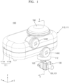
- FIG. 1 is a perspective view illustrating a pump according to embodiments of the present disclosure.
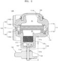
- FIG. 2 is a cross-sectional view taken along line I-I of FIG. 1 .
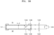
- FIGS. 3A and 3B are schematic diagrams illustrating the reaction in a first electrode body and a second electrode body with respect to a membrane, according to embodiments of the present disclosure.
- FIG. 4 is a partial enlarged view illustrating a housing and a shaft part movably connected to the housing, according to an embodiment of the present disclosure.
- FIG. 5 is a partial bottom view illustrating a discharge passage after taken along line II-II of FIG. 4 , according to an embodiment of the present disclosure.
- FIG. 6 is a diagram partially illustrating a cross-section taken along line III-III of FIG. 5 .
- a pump 100 may include a housing 110, a shaft part 120, a power generation part 140, a stopper part 150, a sealing part 170, an injection port 180, and a deformation part 190.
- the housing 110 is provided with a shaft hole part 112H on one side (a lower side in FIG. 1 ), and the shaft part 120 having a certain length may extend to the outside of the housing 110 through the shaft hole part 112H.
- the housing 110 may include a body part 111, and the shaft hole part 112H may be formed in a protrusion part 112 extending to one side (a lower side in FIG. 1 ).
- the diameter of the protrusion part 112 formed in the housing 110 according to an embodiment of the present disclosure may be formed to be less than the diameter of the body part 111.
- the housing 110 may include a first sub-body 111A and a second sub-body 111B.
- the first sub-body 111A and the second sub-body 111B may be coupled to each other with the power generation part 140, which will be described later, specifically the membrane 141 therebetween.
- a body hole part 111H and the shaft hole part 112H may be formed in the body part 111 according to an embodiment of the present disclosure.
- the body hole part 111H may be formed in the first sub-body 111A arranged on the other side opposite to the second sub-body where the shaft hole part 112H is formed with respect to the power generation part 140, specifically the membrane 141.
- a deformation part 190 which will be described later, may be connected to the first sub-body 111A where the body hole part 111H according to an embodiment of the present disclosure is formed. Specifically, the deformation part 190 may cover the body hole part 111H and may be connected to the first sub-body 111A.
- a discharge passage 112P may be formed such that a certain distance is formed between the second sub-body 111B according to an embodiment of the present disclosure, specifically the inner circumferential surface of the shaft hole part 112H formed in the protrusion part 112, and the shaft part 120, which will be described later, and the inner space of the housing 110 communicates with the external space thereof.
- the discharge passage 112P is formed by the outer circumferential surface of the shaft part 120 and the inner circumferential surface of the shaft hole part 112H spaced apart from each other by a certain distance. Due to this, the inner space and the outer space of the housing 110 may communicate with each other with respect to the shaft hole part 112H.
- the width of the discharge passage 112P may increase or decrease along the circumference with respect to the longitudinal central axis AX of the shaft part 120.
- the distance from a first position to the inner circumferential surface of the shaft hole part 112H in the circumferential direction with respect to the longitudinal central axis of the shaft part 120 is formed as a first distance r1
- the distance from a second position to the inner circumferential surface of the shaft hole part 112H after a certain angle, specifically 45 degrees clockwise, is formed as a second distance r2.
- the second distance r2 may be formed to be relatively greater than the first distance r1.
- the shaft part 120 according to an embodiment of the present disclosure, specifically the shaft body 121, is formed to have a constant radius with respect to the longitudinal central axis AX.
- a certain distance is formed between the outer circumferential surface of the shaft part 120 and the inner circumferential surface of the shaft hole part 112H formed in the housing 110, specifically the protrusion part 112, and the discharge passage 112P may be formed.
- the pump 100 may be supplied with the fluid from the outside to the inside of the housing 110 through the injection port 180, which will be described later.
- the fluid F is discharged through between the contact part 125 and the inner circumferential surface of the protrusion part 112 due to the pressure inside the housing 110 during the supply process, and the fluid F exists in the remaining space RA.
- Such fluid F has to be removed.
- an additional process of evaporating the fluid F by providing hot air, etc. to the remaining space RA formed inside the protrusion part 112 is required, which makes the manufacturing process complicated.
- the fluid F when the fluid F has not been removed through the process described above, the fluid F existing in the remaining space RA is discharged to the outside through the shaft hole part 112H due to the reciprocating motion of the shaft part 120 during the process of driving the pump 100 and the liquid medicine injection device including the pump 100.
- the fluid F may contact electrical components such as a circuit board arranged on the pump 100 side inside the liquid medicine injection device, and a short may occur.
- the discharge passage 112P is formed in the housing 110 according to an embodiment of the present disclosure.
- the width of the discharge passage 112P is set to increase or decrease along the circumference with respect to the longitudinal central axis AX of the shaft part 120. While the longitudinal central axis AX of the shaft part 120 is maintained, the fluid F may be discharged through the discharge passage 112P formed between the outer circumferential surface of the shaft part 120 and the inner circumferential surface of the shaft hole part 112H. Accordingly, there is an effect of quickly discharging and removing the fluid F existing in the remaining space RA.
- the fluid F may be discharged through the discharge passage 112P, there is no need for an additional process of evaporating the fluid in the remaining space RA by separately providing hot air. Accordingly, there is an effect of simplifying the process of manufacturing the pump 100 and the liquid medicine injection device including the pump 100.
- the fluid F in the remaining space RA is discharged to the outside through the discharge passage 112P, there is an effect in which it is possible to prevent the fluid F from contacting the electrical components (e.g., a substrate) installed inside the liquid medicine injection device, and to prevent a short phenomenon that may occur due to the contact between the electrical components and the fluid F.
- the electrical components e.g., a substrate
- the shaft hole part 112H may be formed to share the center with the longitudinal central axis AX of the shaft part 120, specifically the shaft body 121.
- the shaft hole part 112H may have a plurality of flat surfaces arranged to face each other.
- the adjacent surfaces may be arranged to form a certain angle. Specifically, the adjacent surfaces may be formed at 90 degrees.
- a section where the surfaces are connected may be bent with a certain curvature and a bent portion (not denoted by reference numeral) may be formed.
- the distance from the longitudinal central axis AX of the shaft part 120 may be formed as the first distance r1, and the distance from the longitudinal central axis AX of the shaft part 120 to a point on the bent portion may be formed as the second distance r2.
- the second distance r2 may be formed to be relatively greater than the first distance r1.
- the distance from the outer circumferential surface of the shaft part 120, specifically the shaft body 121, which is formed with the same radius in the circumferential direction with respect to the longitudinal central axis AX, to the inner circumferential surface of the shaft hole part 112H may be formed differently.
- the discharge passage 112P may be formed between the outer circumferential surface of the shaft body 121 and the inner circumferential surface of the shaft hole part 112H.
- the shaft hole part 112H according to an embodiment of the present disclosure has four flat sections formed along the inner circumferential surface, and the bent portion may be formed between a pair of adjacent sections.
- the distance from the outer circumferential surface of the shaft body 121 to the inner circumferential surface of the shaft hole part 112H is formed to be relatively greater than the distance from the outer circumferential surface of the shaft body 121 to the inner circumferential surface of the shaft hole part 112H in the flat section. Accordingly, the discharge passage 112P may be formed between the shaft body 121 and the inner circumferential surface of the shaft hole part 112H, and there is an effect in which the fluid F existing in the remaining space RA formed inside the housing 110 may be smoothly discharged to the outside of the housing 110 through the discharge passage 112P.
- the shaft part 120 extends to the outside of the housing 110 through the shaft hole part 112H formed in the housing 110, and may include a shaft body 121 and a contact part 125.
- the shaft part 120 may reciprocate in a first direction from the inner space of the housing 110 toward the shaft hole part 112H (a direction from the top to the bottom in FIG. 2 ) and in a second direction opposite to the first direction (a direction from the bottom to the top in FIG. 2 ).
- the reciprocating motion of the shaft part 120 may depend on the flow of fluid moving in both directions (the vertical direction in FIG. 2 ) of the membrane 141.
- the shaft body 121 passes through the shaft hole part 112H and may be formed to extend along the longitudinal central axis AX.
- a first part 121A of the shaft body 121 may be arranged inside the housing 110, and a second part 121B thereof may extend to the outside of the housing 110 through the shaft hole part 112H.
- the shaft body 121 may reciprocate in the vertical direction (Z-axis direction) in FIGS. 1 and 2 .
- the first part 121A may linearly reciprocate in the inner space of the housing 110, for example, in the inner space corresponding to the protrusion part 112.
- the first part 121A may be formed as a certain section of the shaft body 121 located in the inner space of the housing 110, for example, from the upper end portion to the section where an extension part 122 is formed to protrude.
- the second part 121B may be formed from the certain section of the shaft body 121 where the extension part 122 is formed to protrude to the lower end portion (in FIG. 2 ) passing through the shaft hole part 112H and exposed to the outside.
- the extension part 122 may be formed to protrude in the radial direction with respect to the longitudinal central axis AX of the shaft body 121 in the first part 121A of the shaft body 121 according to an embodiment of the present disclosure.
- the diameter of the extension part 122 may be formed to be greater than the diameter of the shaft hole part 112H. This prevents the first part 121A of the shaft body 121 from being released from the housing 110.
- the distance from the center of the shaft body 121 to the outer circumferential surface of the extension part 122 may be formed to be relatively greater than the shortest distance from the center of the shaft body 121 to the inner circumferential surface of the shaft hole part 112H.
- the second part 121B of the shaft body 121 have a diameter less than a diameter of the shaft hole part 112H.
- the second part 121B may be coupled to a movement control part 130 arranged outside the housing 110.
- the contact part 125 may be connected to one end portion of the shaft body 121 arranged inside the housing 110, specifically to the first part 121A of the shaft body 121, and may be in contact with the inner circumferential surface of the housing 110 arranged outside the shaft body 121.
- the contact part 125 may be formed of a rubber material and is in contact with the inner circumferential surface of the housing 110, the leakage of the fluid between the shaft part 120 and the housing 110 may be prevented.
- a space defined by the inner surface of the housing 110 and the inner surface of the shaft part 120 is a closed space.
- the fluid exists in the space. Since the shaft part 120, specifically the contact part 125, is in contact with the inner circumferential surface of the protrusion part 112 formed in the housing 110, the leakage of the fluid between the contact part 125 and the inner circumferential surface of the protrusion part 112 may be prevented.
- the contact part 125 may be connected to and arranged at one end portion (the upper end portion in FIG. 2 ) of the shaft body 121.
- the contact part 125 may have an O-ring shape and may cover the side surface of the first part 121A of the shaft body 121.
- the contact part 125 may prevent the fluid existing inside the housing 110 from leaking to the outside of the housing 110 through the shaft hole part 112H.
- the leakage of the fluid contained in the housing 110 may be more effectively prevented by making the distance from the first part 121A of the shaft body 121 to the movement control part 130 equal to or less than the inner length of the protrusion part 112.
- the movement control part 130 is coupled to the other end portion (the lower end portion in FIG. 2 ) opposite to one end portion (the upper end portion in FIG. 2 ) of the shaft part 120 arranged inside the housing 110 and is movable in conjunction with the movement of the shaft part 120.
- the movement control part 130 may be connected to the shaft part 120, specifically the second part 121B of the shaft body 121.
- the movement control part 130 may move along the longitudinal central axis AX of the shaft part 120 in conjunction with the reciprocating motion of the shaft part 120.
- the movement control part 130 moves in conjunction with the reciprocating motion of the shaft part 120, power may be transmitted to a reservoir (not shown) that contains liquid medicine, and there is an effect of allowing the liquid medicine to be injected from the reservoir into the body of the user in a fixed amount.
- the present disclosure relates to the pump 100 for driving the liquid medicine injection device, the description of the configuration of the reservoir connected to the movement control part 130 and allowing the liquid medicine to be discharged into the body of the user by receiving power from the movement control part 130 moving in conjunction with the reciprocating motion of the shaft part 120, or the like is omitted.
- the stopper part 150 may be contactably arranged on either side of the movement control part 130 through which the shaft body 121 according to an embodiment of the present disclosure is connected.
- the stopper part 150 may be coupled along the outer circumferential surface of to the shaft part 120, specifically the shaft body 121, and may be in contact with the movement control part 130.
- a plurality of stopper parts 150 may be provided, may be located on both sides (the upper and lower sides in FIG. 2 ) of the movement control part 130, and may be connected to the shaft body 121.
- the movement control part 130 may be prevented from moving on the shaft body 121 along the longitudinal central axis AX.
- the movement control part 130 since the movement control part 130 is prevented from moving on the shaft body 121, the movement control part 130 may move only as far as the movement distance of the shaft body 121 in conjunction with the reciprocating motion of the shaft body 121. Due to the reciprocating motion in the preset section, power is transmitted to the reservoir (not shown), etc., which provides an effect of allowing a fixed amount of liquid medicinal to be injected into the body of the user.
- the power generation part 140 is arranged inside the housing 110 and may transmit power to the shaft part 120.
- the power generation part 140 may include a membrane 141, a first electrode body 143, and a second electrode body 145.
- the power generation part 140 may generate power as the fluid arranged inside the housing 110 moves in both directions of the membrane 141, and the shaft part 120 may reciprocate within the housing 110.
- the membrane 141 may be arranged in the inner space of the housing 110, for example, in the inner space corresponding to the body part 111.
- the membrane 141 may divide the inner space of the housing 110 into a plurality of spaces.
- the inner space may include a first space S1 and a second space S2 respectively located on both sides (the upper and lower sides in FIG. 2 ) with respect to the membrane 141.
- a space relatively far from the shaft part 120 with respect to the membrane 141 may be the first space S1, and a space adjacent to the shaft part 120 with respect to the membrane 141 may be referred to as the second space S2.
- the space formed by the shaft part 120, specifically the contact part 125, and the housing 110, specifically the inner circumferential surface of the protrusion part 112, may be defined as the remaining space RA.
- the remaining space may refer to a space formed between the contact part 125 and one surface of the protrusion part 112, in which the shaft hole part 112H is formed, in the inner space of the protrusion part 112 formed in the housing 110.
- the membrane 141 may have a porous structure that allows the fluid and ions to move.
- the membrane 141 may be, for example, a frit-type membrane 141 manufactured by sintering spherical silica with heat.
- the spherical silica used to form the membrane 141 may have a diameter of about 20 nm to about 500 nm, specifically about 30 nm to about 300 nm, and more specifically, about 40 nm to about 200 nm.
- the membrane 141 includes the spherical silica, but the membrane 141 is not limited thereto.
- the membrane 141 may be formed of a material that may cause an electrokinetic phenomenon due to zetapotential, such as porous silica or porous alumina.
- the membrane 141 may have a thickness of about 20 ⁇ m to about 10 mm, specifically about 300 ⁇ m to about 5 mm, and more specifically, about 1,000 ⁇ m to about 4 mm.
- the first electrode body 143 and the second electrode body 145 may be respectively arranged on both sides of the membrane 141.
- the first electrode body 143 may include a first porous plate 143A and a first strip 143B arranged on a first side of the membrane 141.
- the second electrode body 145 may include a second porous plate 145A and a second strip 145B arranged on a second side of the membrane 141.
- the first porous plate 143A and the second porous plate 145A may be respectively arranged to be in contact with main surfaces on both sides of the membrane 141.
- the first porous plate 143A and the second porous plate 145A may effectively move the fluid and ions through thee porous structures thereof.
- the first porous plate 143A and the second porous plate 145A may have a structure in which an electrochemical reactant is formed in a porous base layer.
- the electrochemical reactant may be formed by electrodeposition or coating on the porous base layer through methods such as electroless plating, vacuum deposition, coating, and sol-gel process.
- the porous base layer may be an insulator.
- the porous base layer may include one or more selected from non-conductive ceramic, non-conductive polymer resin, non-conductive glass, and any combination thereof.
- the non-conductive ceramic may include, for example, one or more selected from the group consisting of rock wool, gypsum, ceramic, cement, and any combination thereof, and specifically, may include one or more selected from the group consisting of rock wool, gypsum, and any combination thereof, but the present disclosure is not limited thereto.
- the non-conductive polymer resin may include, for example, one or more selected from the group consisting of: synthetic fiber selected from the group consisting of polypropylene, polyethylene terephthalate, polyacrylonitrile, and any combination thereof; natural fiber selected from the group consisting of wool, cotton, and any combination thereof; sponge; a porous material derived from living organisms, for example, the bones of living organisms; and any combination thereof, but the present disclosure is not limited thereto.
- the non-conductive glass may include one or more selected from the group consisting of glass wool, glass frit, porous glass, and any combination thereof, but the present disclosure is not limited thereto.
- the porous base layer may have a pore size of about 0.1 ⁇ m to about 500 ⁇ m, specifically about 5 ⁇ m to about 300 ⁇ m, and more specifically, about 10 ⁇ m to about 200 ⁇ m.
- the fluid and ions may be effectively moved, thereby improving the stability, lifespan characteristics, and efficiency of the pump 100.
- the electrochemical reactant may include a material that may form a pair of reactions in which an oxidizing electrode and a reducing electrode exchange cations, for example, hydrogen ions during an electrode reaction of the first electrode body 143 and the second electrode body 145, and at the same time, may form a reversible electrochemical reaction.
- the electrochemical reactant may include, for example, one or more selected from the group consisting of silver/silver oxide, silver/silver chloride, MnO(OH), polyaniline, polypyrrole, polythiophene, polythionine, quinone-based polymer, and any combination thereof.
- the first strip 143B and the second strip 145B may be respectively arranged at the edges of the first porous plate 143A and the second porous plate 145A, and may be connected to a first terminal 143C and a second terminal 145C arranged outside the housing 110.
- the first strip 143B and the second strip 145B may each include a conductive material, such as silver or copper.
- the fluid provided in the inner space of the housing 110 may include a first fluid and a second fluid having different phases.
- the first fluid may include a liquid such as water
- the second fluid may include a gas such as air.
- the first fluid existing in the inner space does not completely fill the inner space. That is, the volume of the inner space is greater than the volume of the first fluid existing in the inner space.
- the second fluid may exist in a portion of the inner space where water does not exist.
- the sealing part 170 may be arranged on either side of the power generation part 140, specifically the membrane 141. Although not illustrated in FIG. 2 , the sealing part 170 may be formed in a ring shape with the area corresponding to the edge of the structure including the membrane 141, the first electrode body 143, and the second electrode body 145.
- the sealing part 170 may block a gap between the inner surface of the housing 110 and the above-described structure, thereby preventing the fluid from moving into the gap.
- the fluid may flow into the inner space of the housing 110 through the injection port 180, as illustrated in FIG. 1 .
- the first fluid and the second fluid may exist in the inner space of the housing 110.
- the fluid F may pass between the contact part 125 provided on the shaft part 120 and the inner circumferential surface of the protrusion part 112 formed in the housing 110 by pressure during the process of injecting the fluid into the inner space of the housing 110 through the injection port 180.
- the fluid that has passed in this way remains in the remaining space RA.
- the discharge passage 112P is formed between the inner circumferential surface of the shaft hole part 112H and the outer circumferential surface of the shaft part 120, specifically the shaft body 121, according to an embodiment of the present disclosure, there is an effect in which the fluid F existing in the remaining space RA may be discharged to the outside of the housing 110.
- the fluid F may be stably discharged to the outside of the housing 110 through the discharge passage 112P, a process of evaporating the fluid F by providing hot air from the outside so as to remove the fluid F not escaping from the remaining space RA is not required, thereby simplifying the manufacturing process.
- the width of the discharge passage 112P increases or decreases along the circumference with respect to the longitudinal central axis AX of the shaft part 120, there is an effect in which the longitudinal central axis AX of the shaft body 121 is prevented from moving, and the discharge passage 112P, which is a separation space, is formed between the outer circumferential surface of the shaft body 121 and the inner circumferential surface of the shaft hole part 112H in a certain section, such that the fluid F is smoothly discharged to the outside.
- FIGS. 3A and 3B are schematic diagrams illustrating the reaction in the first electrode body 143 and the second electrode body 145 with respect to the membrane 141.
- the first electrode body 143 and the second electrode body 145 may be electrically connected to a power supply part 200 through the first terminal 143C and the second terminal 145C, respectively.
- a power supply part 200 By alternately changing the polarity of the voltage supplied by the power supply part 200, the direction of movement of the liquid such as water may be changed.
- the power generation part 140 uses silver/silver oxide as the electrochemical reactant and the first fluid is a solution including water is described.
- the reaction of Ag(s)+H 2 O ⁇ Ag 2 O(s)+2H + +2e- occurs in the first electrode body 143, and the reaction of Ag 2 O(s)+2H + +2e- ⁇ Ag(s)+H 2 O occurs in the second electrode body 145.
- Cations (M n+ , for example, hydrogen ions) generated according to the oxidation reaction in the first electrode body 143 pass through the membrane 141 and move toward the second electrode body 145 by the voltage difference. At this time, a certain pressure may be generated while water (H 2 O) is moving together with cations.
- the electrochemical reactant consumed when used as the oxidizing electrode is recovered when used as the reducing electrode.
- the reducing electrode is also recovered. Accordingly, the first electrode body 143 and the second electrode body 145 may continuously react according to the voltage supply of the power supply part 200.
- the shaft part 120 may pass through the shaft hole part 112H and move in the vertical direction (in FIG. 2 ) along the longitudinal central axis AX.
- the fluid F may generate power while moving from the first space S1 to the second space S2 respectively formed above and below the membrane 141 or from the second space S2 to the first space S1.
- the deformation part 190 is connected to the housing 110, and may cover the body hole part 111H, which is formed on the other side (the upper side in FIG. 2 ) opposite to one side (the lower side in FIG. 2 ) of the housing 110 where the shaft hole part 112H is formed, and may be connected to the housing 110.
- the deformation part 190 may be formed of an elastically deformable material, and a preset region may be formed of an elastically deformable material.
- the region formed of an elastically deformable material may be a central region of the deformation part 190.
- the central region of the deformation part 190 is formed to be convex in the outward direction, but the present disclosure is not limited thereto, and various modifications are possible.
- the central region of the deformation part 190 may be formed to be concave in the outward direction.
- the volume of the inner region of the deformation part 190 in the inner space of the housing 110 may increase or decrease.
- the shape of the deformation part 190 may be deformed depending on the inner pressure of the inner space, and negative pressure may be formed in the inner space.
- the deformation part 190 when compression occurs in the inner space of the housing 110, specifically the upper side of the membrane 141 (in FIG. 2 ), the deformation part 190 has the elastic restoring force in the direction of being formed to be convex in the outward direction. Accordingly, there is an effect of making compression easier.
- the gas may be contained in the inner space of the housing 110 where the deformation part 190 is installed. Accordingly, there is an effect of performing a buffer function.
- the pump 100 may be a small pump 100 used in a device for injecting medicine such as insulin.
- the use of the pump 100 is not particularly limited as long as the pump 100 linearly moves the shaft part 120 by using the structure and mechanism as described above.
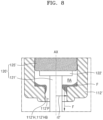
- FIG. 7 is a partial bottom view illustrating a discharge passage after taken along line II-II of FIG. 4 , according to another embodiment of the present disclosure.
- FIG. 8 is a diagram partially illustrating a cross-section taken along line IV-IV of FIG. 7 .
- the pump may include a housing 110', a shaft part 120', a movement control part, a power generation part, a stopper part, a sealing part, an injection port, and a deformation part.
- the pump according to another embodiment of the present disclosure differs from the pump 100 according to an embodiment of the present disclosure in the shape of an inner circumferential surface of a shaft hole part 112'H formed in the housing 110', the following description is given focusing on the difference.
- the shaft hole part 112'H according to another embodiment of the present disclosure is formed along the inner circumferential surface of the housing 110', specifically a protrusion part 112' formed to protrude in the outward direction.
- the shaft part 120' may pass through the shaft hole part 112'H and be connected to the movement control part arranged outside the housing 110'.
- the shaft hole part 112'H may share the center with the shaft part 120' that reciprocates along the longitudinal central axis AX within the shaft hole part 112'H.
- the inner circumferential surface of the shaft hole part 112'H may have at least one curved section formed in the circumferential direction with respect to the center.
- the inner circumferential surface of the shaft hole part 112'H may include convex portions 112'HA and concave portions 112'HB alternately arranged in the circumferential direction with respect to the center.
- a distance to the convex portion 112'HA formed convexly toward the center along the inner circumferential surface of the shaft hole part 112'H may be formed as a first distance r1'
- a distance to the concave portion 112'HB formed concavely toward the center along the inner circumferential surface of the shaft hole part 112'H may be formed as a second distance r2'.
- the second distance r2' may be formed to be relatively greater than the first distance r1', and a discharge passage 112'P may be formed between the concave portion 112'HB formed between the convex portions 112'HA adjacent to each other and the outer circumferential surface of the shaft part 120',
- a plurality of discharge passages 112'P may be formed to correspond to the concave portions 112'HB. This provides an effect of discharging, to the outside, the fluid F existing in the remaining space RA, which is the inner space surrounded by the contact part 125', the inner circumferential surface of the protrusion part 112', and one surface of the protrusion part 112' where the shaft hole part 112'H is formed, in the inner space of the housing 110',
- the fluid F may remain in the remaining space RA while passing between the outer circumferential surface of the contact part 125' and the inner circumferential surface of the protrusion part 112' due to pressure during the process of injecting the fluid into the housing 110' through the injection port.
- the pump according to another embodiment of the present disclosure is the same as the pump 100 according to an embodiment of the present disclosure in the configuration, operation principle, and effects of the shaft part, the movement control part, the power generation part, the stopper part, the sealing part, the injection port, and the deformation part, except that the convex portion 112'HA and the concave portion 112'HB are repeatedly formed toward the curved section having a certain curvature along the inner circumference of the shaft hole part 112'H formed in the housing 110', specifically, toward the center of the shaft hole 112'H, the inner circumferential surface of the shaft hole part 112'H and the outer circumferential surface of the shaft part 120' are spaced apart from each other by a certain distance, and the discharge passage 112'P is formed such that the inner space of the housing 110' communicates with the outer space.
- a pump is provided.
- embodiments of the present disclosure may be applied to industrially applicable pumps provided in devices that inject liquid medicine into the body of a patient.
Landscapes
- Engineering & Computer Science (AREA)
- Health & Medical Sciences (AREA)
- Mechanical Engineering (AREA)
- General Engineering & Computer Science (AREA)
- Hematology (AREA)
- Anesthesiology (AREA)
- Biomedical Technology (AREA)
- Heart & Thoracic Surgery (AREA)
- Vascular Medicine (AREA)
- Life Sciences & Earth Sciences (AREA)
- Animal Behavior & Ethology (AREA)
- General Health & Medical Sciences (AREA)
- Public Health (AREA)
- Veterinary Medicine (AREA)
- Infusion, Injection, And Reservoir Apparatuses (AREA)
- Dermatology (AREA)
Applications Claiming Priority (2)
| Application Number | Priority Date | Filing Date | Title |
|---|---|---|---|
| KR1020210187460A KR102683864B1 (ko) | 2021-12-24 | 2021-12-24 | 펌프 |
| PCT/KR2021/019988 WO2023120796A1 (ko) | 2021-12-24 | 2021-12-28 | 펌프 |
Publications (2)
| Publication Number | Publication Date |
|---|---|
| EP4454679A1 true EP4454679A1 (de) | 2024-10-30 |
| EP4454679A4 EP4454679A4 (de) | 2025-02-05 |
Family
ID=86902995
Family Applications (1)
| Application Number | Title | Priority Date | Filing Date |
|---|---|---|---|
| EP21969160.7A Withdrawn EP4454679A4 (de) | 2021-12-24 | 2021-12-28 | Pumpe |
Country Status (4)
| Country | Link |
|---|---|
| US (1) | US12527908B2 (de) |
| EP (1) | EP4454679A4 (de) |
| KR (2) | KR102683864B1 (de) |
| WO (1) | WO2023120796A1 (de) |
Family Cites Families (14)
| Publication number | Priority date | Publication date | Assignee | Title |
|---|---|---|---|---|
| US3011808A (en) * | 1959-12-03 | 1961-12-05 | John W Mecom | Pump packing |
| US5755361A (en) * | 1996-01-11 | 1998-05-26 | The Fountainhead Group, Inc. | Pump sprayer |
| KR101106286B1 (ko) * | 2009-11-02 | 2012-01-18 | 경북대학교 산학협력단 | 전기삼투식 약물 펌프 및 그 시스템 |
| CA2795837A1 (en) | 2010-03-09 | 2011-09-15 | Woonsup Shin | Electro-osmotic pumps, systems, methods, and compositions |
| KR101752326B1 (ko) | 2016-01-15 | 2017-06-29 | 중소기업은행 | 전기삼투압을 이용한 펌프모듈 |
| AU2017200739B2 (en) * | 2016-02-05 | 2022-06-09 | Graco Minnesota Inc. | Fluid pump leakage diversion |
| KR101910932B1 (ko) * | 2016-08-31 | 2018-10-23 | 이오플로우(주) | 전기 삼투 펌프 |
| KR102101938B1 (ko) * | 2018-08-20 | 2020-04-17 | 이오플로우(주) | 펌프 |
| KR102173812B1 (ko) * | 2019-08-20 | 2020-11-04 | 이오플로우(주) | 전기 삼투압 펌프 |
| JP7157241B2 (ja) * | 2018-08-20 | 2022-10-19 | イオフロー カンパニーリミテッド | 電気浸透圧ポンプ |
| KR102379943B1 (ko) * | 2018-08-20 | 2022-03-31 | 이오플로우 주식회사 | 펌프 |
| KR102477258B1 (ko) * | 2019-08-20 | 2022-12-14 | 이오플로우(주) | 전기 삼투압 펌프 |
| KR102351143B1 (ko) | 2019-10-04 | 2022-01-14 | 이오플로우 주식회사 | 약액 주입 장치 |
| KR102452513B1 (ko) * | 2019-12-23 | 2022-10-11 | 이오플로우(주) | 복막 투석 디바이스 |
-
2021
- 2021-12-24 KR KR1020210187460A patent/KR102683864B1/ko active Active
- 2021-12-28 WO PCT/KR2021/019988 patent/WO2023120796A1/ko not_active Ceased
- 2021-12-28 EP EP21969160.7A patent/EP4454679A4/de not_active Withdrawn
-
2024
- 2024-06-21 US US18/749,717 patent/US12527908B2/en active Active
- 2024-07-05 KR KR1020240089267A patent/KR20240112799A/ko not_active Withdrawn
Also Published As
| Publication number | Publication date |
|---|---|
| KR20230097705A (ko) | 2023-07-03 |
| WO2023120796A1 (ko) | 2023-06-29 |
| KR102683864B1 (ko) | 2024-07-11 |
| EP4454679A4 (de) | 2025-02-05 |
| US12527908B2 (en) | 2026-01-20 |
| US20240335604A1 (en) | 2024-10-10 |
| KR20240112799A (ko) | 2024-07-19 |
Similar Documents
| Publication | Publication Date | Title |
|---|---|---|
| US20240382672A1 (en) | Electroosmotic pump | |
| CN112654383B (zh) | 电渗泵 | |
| KR102477258B1 (ko) | 전기 삼투압 펌프 | |
| KR102379943B1 (ko) | 펌프 | |
| KR20230022296A (ko) | 약액 제어 주입 디바이스 | |
| KR102173812B1 (ko) | 전기 삼투압 펌프 | |
| EP4454679A1 (de) | Pumpe | |
| KR20220140453A (ko) | 복막 투석 디바이스 | |
| JP7378624B2 (ja) | 駆動時間対称アルゴリズムが適用された薬液注入装置、駆動時間対称化方法及びその記録媒体 | |
| KR102534944B1 (ko) | 전기 삼투압 펌프 | |
| US20240342363A1 (en) | Electroosmotic pump | |
| EP4454680A1 (de) | Elektroosmotische pumpe | |
| KR20240040447A (ko) | 전기 삼투 펌프 |
Legal Events
| Date | Code | Title | Description |
|---|---|---|---|
| STAA | Information on the status of an ep patent application or granted ep patent |
Free format text: STATUS: THE INTERNATIONAL PUBLICATION HAS BEEN MADE |
|
| PUAI | Public reference made under article 153(3) epc to a published international application that has entered the european phase |
Free format text: ORIGINAL CODE: 0009012 |
|
| STAA | Information on the status of an ep patent application or granted ep patent |
Free format text: STATUS: REQUEST FOR EXAMINATION WAS MADE |
|
| 17P | Request for examination filed |
Effective date: 20240722 |
|
| AK | Designated contracting states |
Kind code of ref document: A1 Designated state(s): AL AT BE BG CH CY CZ DE DK EE ES FI FR GB GR HR HU IE IS IT LI LT LU LV MC MK MT NL NO PL PT RO RS SE SI SK SM TR |
|
| A4 | Supplementary search report drawn up and despatched |
Effective date: 20250109 |
|
| RIC1 | Information provided on ipc code assigned before grant |
Ipc: F04B 43/00 20060101ALI20250102BHEP Ipc: F04B 19/00 20060101ALI20250102BHEP Ipc: F04B 13/00 20060101ALI20250102BHEP Ipc: F04B 9/103 20060101ALI20250102BHEP Ipc: A61M 5/168 20060101ALI20250102BHEP Ipc: A61M 5/142 20060101AFI20250102BHEP |
|
| DAV | Request for validation of the european patent (deleted) | ||
| DAX | Request for extension of the european patent (deleted) | ||
| STAA | Information on the status of an ep patent application or granted ep patent |
Free format text: STATUS: THE APPLICATION IS DEEMED TO BE WITHDRAWN |
|
| 18D | Application deemed to be withdrawn |
Effective date: 20250729 |