EP4454576A1 - Vorrichtung zur ausgabe eines antriebssignals an ein chirurgisches instrument - Google Patents
Vorrichtung zur ausgabe eines antriebssignals an ein chirurgisches instrument Download PDFInfo
- Publication number
- EP4454576A1 EP4454576A1 EP22910192.8A EP22910192A EP4454576A1 EP 4454576 A1 EP4454576 A1 EP 4454576A1 EP 22910192 A EP22910192 A EP 22910192A EP 4454576 A1 EP4454576 A1 EP 4454576A1
- Authority
- EP
- European Patent Office
- Prior art keywords
- circuit board
- ultrasonic
- energy circuit
- frequency electric
- frequency
- Prior art date
- Legal status (The legal status is an assumption and is not a legal conclusion. Google has not performed a legal analysis and makes no representation as to the accuracy of the status listed.)
- Pending
Links
Images



Classifications
-
- A—HUMAN NECESSITIES
- A61—MEDICAL OR VETERINARY SCIENCE; HYGIENE
- A61B—DIAGNOSIS; SURGERY; IDENTIFICATION
- A61B17/00—Surgical instruments, devices or methods
- A61B17/32—Surgical cutting instruments
- A61B17/320068—Surgical cutting instruments using mechanical vibrations, e.g. ultrasonic
-
- A—HUMAN NECESSITIES
- A61—MEDICAL OR VETERINARY SCIENCE; HYGIENE
- A61B—DIAGNOSIS; SURGERY; IDENTIFICATION
- A61B18/00—Surgical instruments, devices or methods for transferring non-mechanical forms of energy to or from the body
- A61B18/04—Surgical instruments, devices or methods for transferring non-mechanical forms of energy to or from the body by heating
- A61B18/12—Surgical instruments, devices or methods for transferring non-mechanical forms of energy to or from the body by heating by passing a current through the tissue to be heated, e.g. high-frequency current
- A61B18/1206—Generators therefor
-
- A—HUMAN NECESSITIES
- A61—MEDICAL OR VETERINARY SCIENCE; HYGIENE
- A61B—DIAGNOSIS; SURGERY; IDENTIFICATION
- A61B17/00—Surgical instruments, devices or methods
- A61B17/32—Surgical cutting instruments
- A61B17/320068—Surgical cutting instruments using mechanical vibrations, e.g. ultrasonic
- A61B17/320092—Surgical cutting instruments using mechanical vibrations, e.g. ultrasonic with additional movable means for clamping or cutting tissue, e.g. with a pivoting jaw
-
- A—HUMAN NECESSITIES
- A61—MEDICAL OR VETERINARY SCIENCE; HYGIENE
- A61B—DIAGNOSIS; SURGERY; IDENTIFICATION
- A61B18/00—Surgical instruments, devices or methods for transferring non-mechanical forms of energy to or from the body
- A61B18/04—Surgical instruments, devices or methods for transferring non-mechanical forms of energy to or from the body by heating
- A61B18/12—Surgical instruments, devices or methods for transferring non-mechanical forms of energy to or from the body by heating by passing a current through the tissue to be heated, e.g. high-frequency current
-
- A—HUMAN NECESSITIES
- A61—MEDICAL OR VETERINARY SCIENCE; HYGIENE
- A61B—DIAGNOSIS; SURGERY; IDENTIFICATION
- A61B18/00—Surgical instruments, devices or methods for transferring non-mechanical forms of energy to or from the body
- A61B18/04—Surgical instruments, devices or methods for transferring non-mechanical forms of energy to or from the body by heating
- A61B18/12—Surgical instruments, devices or methods for transferring non-mechanical forms of energy to or from the body by heating by passing a current through the tissue to be heated, e.g. high-frequency current
- A61B18/14—Probes or electrodes therefor
-
- A—HUMAN NECESSITIES
- A61—MEDICAL OR VETERINARY SCIENCE; HYGIENE
- A61B—DIAGNOSIS; SURGERY; IDENTIFICATION
- A61B18/00—Surgical instruments, devices or methods for transferring non-mechanical forms of energy to or from the body
- A61B18/04—Surgical instruments, devices or methods for transferring non-mechanical forms of energy to or from the body by heating
- A61B18/12—Surgical instruments, devices or methods for transferring non-mechanical forms of energy to or from the body by heating by passing a current through the tissue to be heated, e.g. high-frequency current
- A61B18/14—Probes or electrodes therefor
- A61B18/1442—Probes having pivoting end effectors, e.g. forceps
- A61B18/1445—Probes having pivoting end effectors, e.g. forceps at the distal end of a shaft, e.g. forceps or scissors at the end of a rigid rod
-
- A—HUMAN NECESSITIES
- A61—MEDICAL OR VETERINARY SCIENCE; HYGIENE
- A61B—DIAGNOSIS; SURGERY; IDENTIFICATION
- A61B17/00—Surgical instruments, devices or methods
- A61B2017/00017—Electrical control of surgical instruments
- A61B2017/00022—Sensing or detecting at the treatment site
- A61B2017/00106—Sensing or detecting at the treatment site ultrasonic
-
- A—HUMAN NECESSITIES
- A61—MEDICAL OR VETERINARY SCIENCE; HYGIENE
- A61B—DIAGNOSIS; SURGERY; IDENTIFICATION
- A61B17/00—Surgical instruments, devices or methods
- A61B17/32—Surgical cutting instruments
- A61B17/320068—Surgical cutting instruments using mechanical vibrations, e.g. ultrasonic
- A61B2017/320082—Surgical cutting instruments using mechanical vibrations, e.g. ultrasonic for incising tissue
-
- A—HUMAN NECESSITIES
- A61—MEDICAL OR VETERINARY SCIENCE; HYGIENE
- A61B—DIAGNOSIS; SURGERY; IDENTIFICATION
- A61B17/00—Surgical instruments, devices or methods
- A61B17/32—Surgical cutting instruments
- A61B17/320068—Surgical cutting instruments using mechanical vibrations, e.g. ultrasonic
- A61B17/320092—Surgical cutting instruments using mechanical vibrations, e.g. ultrasonic with additional movable means for clamping or cutting tissue, e.g. with a pivoting jaw
- A61B2017/320095—Surgical cutting instruments using mechanical vibrations, e.g. ultrasonic with additional movable means for clamping or cutting tissue, e.g. with a pivoting jaw with sealing or cauterizing means
-
- A—HUMAN NECESSITIES
- A61—MEDICAL OR VETERINARY SCIENCE; HYGIENE
- A61B—DIAGNOSIS; SURGERY; IDENTIFICATION
- A61B18/00—Surgical instruments, devices or methods for transferring non-mechanical forms of energy to or from the body
- A61B2018/00571—Surgical instruments, devices or methods for transferring non-mechanical forms of energy to or from the body for achieving a particular surgical effect
- A61B2018/00607—Coagulation and cutting with the same instrument
-
- A—HUMAN NECESSITIES
- A61—MEDICAL OR VETERINARY SCIENCE; HYGIENE
- A61B—DIAGNOSIS; SURGERY; IDENTIFICATION
- A61B18/00—Surgical instruments, devices or methods for transferring non-mechanical forms of energy to or from the body
- A61B2018/00636—Sensing and controlling the application of energy
- A61B2018/00642—Sensing and controlling the application of energy with feedback, i.e. closed loop control
- A61B2018/00654—Sensing and controlling the application of energy with feedback, i.e. closed loop control with individual control of each of a plurality of energy emitting elements
-
- A—HUMAN NECESSITIES
- A61—MEDICAL OR VETERINARY SCIENCE; HYGIENE
- A61B—DIAGNOSIS; SURGERY; IDENTIFICATION
- A61B18/00—Surgical instruments, devices or methods for transferring non-mechanical forms of energy to or from the body
- A61B2018/00636—Sensing and controlling the application of energy
- A61B2018/00696—Controlled or regulated parameters
- A61B2018/00702—Power or energy
-
- A—HUMAN NECESSITIES
- A61—MEDICAL OR VETERINARY SCIENCE; HYGIENE
- A61B—DIAGNOSIS; SURGERY; IDENTIFICATION
- A61B18/00—Surgical instruments, devices or methods for transferring non-mechanical forms of energy to or from the body
- A61B2018/00636—Sensing and controlling the application of energy
- A61B2018/00696—Controlled or regulated parameters
- A61B2018/00755—Resistance or impedance
-
- A—HUMAN NECESSITIES
- A61—MEDICAL OR VETERINARY SCIENCE; HYGIENE
- A61B—DIAGNOSIS; SURGERY; IDENTIFICATION
- A61B18/00—Surgical instruments, devices or methods for transferring non-mechanical forms of energy to or from the body
- A61B2018/00994—Surgical instruments, devices or methods for transferring non-mechanical forms of energy to or from the body combining two or more different kinds of non-mechanical energy or combining one or more non-mechanical energies with ultrasound
-
- A—HUMAN NECESSITIES
- A61—MEDICAL OR VETERINARY SCIENCE; HYGIENE
- A61B—DIAGNOSIS; SURGERY; IDENTIFICATION
- A61B18/00—Surgical instruments, devices or methods for transferring non-mechanical forms of energy to or from the body
- A61B18/04—Surgical instruments, devices or methods for transferring non-mechanical forms of energy to or from the body by heating
- A61B18/12—Surgical instruments, devices or methods for transferring non-mechanical forms of energy to or from the body by heating by passing a current through the tissue to be heated, e.g. high-frequency current
- A61B18/1206—Generators therefor
- A61B2018/1246—Generators therefor characterised by the output polarity
- A61B2018/1253—Generators therefor characterised by the output polarity monopolar
-
- A—HUMAN NECESSITIES
- A61—MEDICAL OR VETERINARY SCIENCE; HYGIENE
- A61B—DIAGNOSIS; SURGERY; IDENTIFICATION
- A61B18/00—Surgical instruments, devices or methods for transferring non-mechanical forms of energy to or from the body
- A61B18/04—Surgical instruments, devices or methods for transferring non-mechanical forms of energy to or from the body by heating
- A61B18/12—Surgical instruments, devices or methods for transferring non-mechanical forms of energy to or from the body by heating by passing a current through the tissue to be heated, e.g. high-frequency current
- A61B18/1206—Generators therefor
- A61B2018/1246—Generators therefor characterised by the output polarity
- A61B2018/126—Generators therefor characterised by the output polarity bipolar
-
- A—HUMAN NECESSITIES
- A61—MEDICAL OR VETERINARY SCIENCE; HYGIENE
- A61B—DIAGNOSIS; SURGERY; IDENTIFICATION
- A61B18/00—Surgical instruments, devices or methods for transferring non-mechanical forms of energy to or from the body
- A61B18/04—Surgical instruments, devices or methods for transferring non-mechanical forms of energy to or from the body by heating
- A61B18/12—Surgical instruments, devices or methods for transferring non-mechanical forms of energy to or from the body by heating by passing a current through the tissue to be heated, e.g. high-frequency current
- A61B18/14—Probes or electrodes therefor
- A61B18/1442—Probes having pivoting end effectors, e.g. forceps
- A61B2018/1452—Probes having pivoting end effectors, e.g. forceps including means for cutting
Definitions
- the present disclosure relates to the field of ultrasonic electrosurgical systems for performing surgical operations , and in particular device for output drive signals to surgical device.
- Both the ultrasonic surgical instrument (referred to ultrasonic scalpel) and the high-frequency electrosurgical instrument (referred to electric scalpel) can be used for surgery.
- the ultrasonic scalpel has good cutting performance, but has poor coagulation performance in the surgical operation.
- the electric scalpel is divided into the monopolar electric scalpel and the bipolar electric scalpel according to the working mode.
- the bipolar electric scalpel has good coagulation performance, but has poor cutting performance in the surgical operation.
- the electrode is arranged on the end effector of the ultrasonic scalpel, the effects of the ultrasonic scalpel and the bipolar electric scalpel can be achieved, and such multifunctional ultrasonic surgical instrument is referred to as "ultrasonic-electric scalpel".
- the ultrasonic-electric scalpel, the ultrasonic scalpel, the monopolar electric scalpel, or the bipolar electric scalpel can be used according to needs, and several surgical instruments therein are often used in one surgery.
- the output devices for driving these surgical instruments are independent devices, and these output devices not only occupy a limited device space of an operating room, but also have a lot of inconvenience in controlling these output devices when they are used, and even affect the operation effect.
- an ultrasonic scalpel is driven by a separate ultrasonic output device, and a monopolar electric scalpel or a bipolar electric scalpel is driven by a separate high-frequency electric output device
- a usage mode in which an ultrasonic output device and a high-frequency electric output device are connected via a cable
- an embodiment of the present disclosure provide an apparatus for outputting drive signals to surgical instrument.
- One aspect of the present disclosure provides device for outputting drive signals to surgical instrument, comprising a housing, wherein the housing is internally provided with a power supply module comprising a power supply module and a power supply circuit board, and the power supply module is configured to provide a power supply; a main board; an ultrasonic energy circuit board connected to the main board and used for generating an ultrasonic drive signal; and a high-frequency electric energy circuit board connected to the main board and used for generating a high-frequency electric drive signal; wherein projections of the ultrasonic energy circuit board and the high-frequency energy circuit board on a bottom face of the housing at least partially overlap, and a shielding unit is provided outside the ultrasonic energy circuit board and/or the high-frequency energy circuit board.
- the ultrasonic energy circuit board is provided with an ultrasonic frequency regulation module and an ultrasonic power regulation module.
- the high-frequency electric energy circuit board is provided with a high-frequency electric frequency regulation module and a high-frequency electric power regulation module.
- the main board is configured to adaptively control the ultrasonic drive signal and the high-frequency electric drive signal, so as to adaptively adjust at least one of the following output parameters: power of the ultrasonic drive signal, frequency of the ultrasonic drive signal, power of the high-frequency electric drive signal, and frequency of the high-frequency electric drive signal.
- the ultrasonic energy circuit board is provided with an ultrasonic signal collection circuit, comprising a first filter module, a first differential amplification module, a second filter module, a first automatic gain control module and a first analog-to-digital conversion module, configured to collect and process signals in a connection circuit between the ultrasonic energy circuit board and the surgical instrument to obtain an ultrasonic feedback signal, and provide the ultrasonic feedback signals to the main board, wherein the ultrasonic feedback signals includes an ultrasonic voltage feedback signal and an ultrasonic current feedback signal.
- an ultrasonic signal collection circuit comprising a first filter module, a first differential amplification module, a second filter module, a first automatic gain control module and a first analog-to-digital conversion module, configured to collect and process signals in a connection circuit between the ultrasonic energy circuit board and the surgical instrument to obtain an ultrasonic feedback signal, and provide the ultrasonic feedback signals to the main board, wherein the ultrasonic feedback signals includes an ultrasonic voltage feedback signal and an ultrasonic current feedback signal.
- the high-frequency electric energy circuit board is provided with a high-frequency electric acquisition circuit, including a third filter module, a second differential amplification module, a fourth filter module, a second automatic gain control module and a second analog-to-digital conversion module, configured to collect and process signals in a connection circuit of a high-frequency electrical energy circuit board and the surgical instrument, so as to obtain a high-frequency electric feedback signal; and provide the high-frequency electric feedback signal to the main board, wherein the high-frequency electric feedback signal includes a high-frequency voltage feedback signal and a high-frequency current feedback signal.
- the main board is configured to control the output parameter based on the ultrasonic feedback signal and the high-frequency electric feedback signal.
- the main board is further configured to obtain an acoustic impedance based on the ultrasonic feedback signal, obtain an electrical impedance based on the high-frequency electric feedback signal, match the acoustic impedance and/or the electrical impedance with impedance data to determine a tissue type, and determine the power of the ultrasonic drive signal and the power of the high-frequency electric drive signal based on the tissue type.
- the main board is further configured to obtain a first phase difference based on the ultrasonic voltage feedback signal and the ultrasonic current feedback signal; obtaining a second phase difference based on the high-frequency voltage feedback signal and the high-frequency current feedback signal; and determine the power of the ultrasonic drive signal and the power of the high-frequency electric drive signal based on the tissue type, the first phase difference, and the second phase difference.
- the main board is configured to determine a cutting stage based on the ultrasonic feedback signal and/or the high-frequency electric feedback signal, and determine the power of the ultrasonic drive signal and the power of the high-frequency electric drive signal based on the cutting stage.
- the ultrasonic energy circuit board includes a first network area and a first application area
- the high-frequency electric energy circuit board includes a second network area and a second application area
- the first network area and the second network area are located close to a side of the main board.
- the ultrasonic energy circuit board is provided with at least one first element crossing the first network area and the first application area the first element is located between a pin of the first network area and a pin of the first application area, and the ultrasonic energy circuit board is provided with a first gap.
- the high-frequency electric energy circuit board is provided with at least one second element crossing the second network power area and the second application area, the second element is located at a position between a pin of the second network power area and a pin of the second application area, and the high-frequency electric energy circuit board is provided with a second gap.
- a distance between any two of the ultrasonic energy circuit board, the high-frequency electric energy circuit board, the main board, the power supply module and the power supply circuit board is not less than 10mm.
- a distance between each of the ultrasonic energy circuit board, the high-frequency electric energy circuit board, the main board, the power supply module and the power supply circuit board and the housing is not less than 10 mm.
- the first shield unit is the first shield enclosure disposed outside the ultrasonic energy circuit board, and a distance between the ultrasonic energy circuit board and a side wall of the first shield enclosure is not less than 10 mm.
- the second shield unit is the second shield enclosure disposed outside the high-frequency electric energy circuit board, and a distance between the high-frequency electric energy circuit board and a side wall of the second shield enclosure is not less than 10 mm.
- the housing is provided with a display screen, and the housing is provided with an interface, comprising one or more of a monopolar electric scalpel positive electrode interface, a monopolar electric scalpel negative electrode interface, a bipolar electric scalpel interface and an ultrasonic-electric scalpel interface.
- an insulating plate having a width of not less than 30 mm is provided at a position between the interface and the display screen.
- the device comprises a loudspeaker, which is arranged below the main board and is fixed on the housing by means of an adapter plate, a closed space is formed between an end face of the loudspeaker and a surface of the housing, and a sound outlet hole is provided at the bottom of the housing.
- the device further comprises a data interface and a download board, wherein the download board is connected to the main board and the data interface and is configured to receive the upgrade data transferred from the data interface and transfer the upgrade data to the main board.
- the power module set further includes a standby battery disposed below the power supply circuit board.
- the ultrasonic energy circuit board and the high-frequency electric energy circuit board are disposed in a stacking manner, and at least one of the ultrasonic energy circuit board and the high-frequency electric energy circuit board is isolated by the shielding unit, the interference of a high-frequency electric energy circuit board on an ultrasonic energy circuit board is effectively controlled, so that the high-frequency electric energy circuit board and the ultrasonic energy circuit board can be packaged in one output device, so that the interference of the high-frequency electric energy circuit board on the ultrasonic energy circuit board is effectively controlled, so that the ultrasonic energy circuit board and the high-frequency electric energy circuit board can be packaged in one output device, and the device can drive the ultrasonic surgical instrument and the high-frequency electrosurgical instrument at the same time, so that the equipment space is saved, the cost is reduced, and the user is also convenient to use.
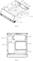
- FIG. 1 to FIG. 9 schematically illustrate a schematic diagram of an apparatus 100 for outputting a drive signal to a surgical instrument according to an embodiment of the present disclosure.
- the following describes the device 100 in the embodiments of the present disclosure with reference to FIG. 1 to FIG. 9 .
- the device 100 for outputting the drive signal to the surgical instrument includes a housing, and the housing is internally provided with a power module set, a main board 123, an ultrasonic energy circuit board 124, and a high-frequency electric energy circuit board.
- the power supply module set includes a power supply module 121 and a power supply circuit board 122, wherein the power supply circuit board 122 is a PWR (Power Supply) board, and functions thereof include, but are not limited to, voltage adjustment, filtering, and the like.
- the power supply module set is configured to provide a stable power supply to the system.
- a power interface 119 may be disposed on the housing and configured to supply power to the power supply module 121.
- the power supply module set can further include a standby battery, for example, disposed below the power supply circuit board 122, so that in an emergency situation, the surgery can be continue through the standby battery, thereby reducing the surgery risk.
- the ultrasonic energy circuit board 124 is connected to the main board 123 and is configured to generate an ultrasonic drive signal.
- a shielding unit may be disposed outside the ultrasonic energy circuit board 124, such as the first shielding cover 125 shown in Fig. 5 . It should be noted that, in order to clearly illustrate the ultrasonic energy circuit board 124, the top surface of the first shielding cover 125 is hidden in Fig. 5 .
- the ultrasonic energy circuit board 124 can convert the power frequency alternating current into an ultrasonic electrical signal matching the ultrasonic transducer, and drive the ultrasonic transducer to convert electrical energy into mechanical energy, so as to drive the blade of the ultrasonic scalpel to vibrate.
- the operating frequency of a ultrasonic scalpel used by surgery is 20 ⁇ 100 kHz, which is most common at 55.5 kHz.
- the signal frequency output by the ultrasonic energy circuit board 124 in the embodiment of the present disclosure is also within this range.
- the high-frequency electric energy circuit board is connected to the main board 123, and is configured to generate a high-frequency electric drive signal.
- a shielding unit may be disposed outside the high-frequency electric energy circuit board, such as the second shielding cover 126 shown in Fig. 5 .
- the frequency range of a high-frequency electrosurgical instrument used for surgery is between 0.3 - 5 MHz.
- the term "high-frequency" in the present disclosure also refers to a frequency between 0.3- 5 MHz. In the embodiments of the present disclosure, the frequency of the drive signal output by the high-frequency electric energy circuit board also within this range.
- the ultrasonic energy circuit board 124 and the high-frequency electric energy circuit board may be disposed in a stacking manner, so that projections of the ultrasonic energy circuit board 124 and the high-frequency electric energy circuit board on the bottom surface of the housing at least partially overlap.
- the ultrasonic energy circuit board 124 is disposed above the high-frequency electric energy circuit board, and the first shielding cover125 and the second shielding cover 126 may be separately disposed outside the two circuit boards.
- the first shielding cover 125 and the second shielding cover 126 are made of metal materials, so as to isolate interference between the ultrasonic energy circuit board 124 and the high-frequency electric energy circuit board, and interference between the ultrasonic energy circuit board 124 and the high-frequency electric energy circuit board and the outside world.
- the shielding unit may also be implemented as a magnetic bead or a magnetic ring.
- a magnetic bead may be disposed on the input line of the ultrasonic energy circuit board 124 and connected in series in the line, so as to reduce unstable components in an input signal, thereby at least partially shielding external interference on the ultrasonic energy circuit board 124.
- a magnetic ring may be disposed, so that an input line of the ultrasonic energy circuit board 124 passes through the magnetic ring, which may also reduce unstable components in an input signal, thereby at least partially shielding external interference on the ultrasonic energy circuit board 124.
- the high-frequency electric energy plate can be shielded in a similar manner, and of course, the shielding unit in the embodiment of the present disclosure can also be implemented by a combination of two or more of a shielding cover, a magnetic bead, or a magnetic ring.
- the ultrasonic energy circuit board and the high-frequency electric energy circuit board are disposed in a stacking manner, and at least one of the ultrasonic energy circuit board and the high-frequency electric energy circuit board is isolated by the shielding unit, so that the interference of the high-frequency electric energy circuit board on the ultrasonic energy circuit board is effectively controlled, so that the high-frequency electric energy circuit board and the ultrasonic energy circuit board can be packaged in one output device.
- the device can simultaneously drive an ultrasonic surgical instrument and a high-frequency electrosurgical instrument, thereby saving the space of the device, facilitating the reduction of costs. It is also convenient for users to use.
- the housing may have a variety of designs.
- the housing may include a U-shaped base 111, a back plate 116, a top cover 112 and a front cover 113.
- the housing may be made of an aluminum alloy material, to reduce the external impact of the device and the interference of the external environment to the device.
- the dimensions of the housing may satisfy a ratio of length, width and height of 1 ⁇ 3:1 ⁇ 3:1, for example, about 2:2: 1, so that the device 100 can be stably placed on the device table.
- the height of the housing may be 150-350 mm, and the size of the overall device may be, for example, 450mm ⁇ 400 mm ⁇ 200 mm, which is light and portable.
- a distance between any two of the ultrasonic energy circuit board 124, the high-frequency electric energy circuit board, the main board 123, the power supply module 121 and the power supply circuit board 122 is not less than a first preset value; a distance between each of the ultrasonic energy circuit board 124, the high-frequency electric energy circuit board, the main board 123, the power supply module 121 and the power supply circuit board 122 and the housing is not less than a second preset value; the distance between the ultrasonic energy circuit board 124 and the side wall of the first shielding cover 125 is not less than a third preset value; a distance between the high-frequency electric energy circuit board and a side wall of the second shielding cover 126 is not less than a fourth preset value.
- the first preset value, the second preset value, the third preset value, and the fourth preset value may be set to 10 mm, preferably 12 mm.
- certain intervals are reserved between various circuit boards, between the circuit boards and the housing, and between the energy circuit board (the ultrasonic energy circuit board, the high-frequency energy circuit board) and the shielding cover, which can reduce interference between circuits.
- the ultrasonic energy circuit board 124 comprises a first network power area and a first application area
- the high-frequency electric energy circuit board comprises a second network power area and a second application area
- the first network power area and the second network power area are located on one side close to the main board 123.
- the first network power area or the second network power area is an area connected to the power supply module set.
- the first application area or the second application area is an area connected to an output end of the device.
- the voltage of the application area is greater than the voltage of the network power area.
- the ultrasonic energy circuit board 124 is provided with at least one first element crossing the first network power area and the first application area, the first element is located at a position between the pin of the first network power area and the pin of the first application area, and the ultrasonic energy circuit board 124 is provided with a first gap.
- the electrical gap between the pin of the first component located in the first power grid area and the pin located in the first application area meets design requirements.
- the first gap is disposed between the two pins, which can further increase the creepage distance and reduce the risk of dielectric electrode integration.
- the above-mentioned two pins are two pins nearest to each other on the ultrasonic energy circuit board 124, and in the case of ensuring the safety of the described two pins, the other pins of the first power grid area and the other pins of the first application area are also necessarily safe.
- the high-frequency electric energy circuit board is provided with at least one second element crossing the second network area and the second application area, the second element is located at a position between a pin of the second network area and a pin of the second application area, and the high-frequency electric energy circuit board is provided with a second gap.
- the electrical gap between the pin of the second component located in the second network area and the pin located in the second application area has met design requirements.
- the second gap is disposed between the two pins, which can further increase the creepage distance and reduce the risk of dielectric electrode formation.
- the above-mentioned two pins are two pins nearest to each other on the high-frequency electric energy circuit board, and in the case of ensuring the safety of the described two pins, other pins of the second network power area and other pins of the second application area are also necessarily safe.
- the ultrasonic energy circuit board 124 is provided with an ultrasonic frequency regulation module and an ultrasonic power regulation module for adjusting the frequency and power of the signal output by the ultrasonic signal generator.
- a high-frequency electric energy circuit board is provided with a high-frequency electric frequency regulation module and a high-frequency electric power regulation module for regulating the frequency and power of a signal output by a high-frequency signal generator.
- the main board 123 may be configured to adaptively control the ultrasonic drive signal and the high-frequency electric drive signal, so as to adaptively adjust at least one of the following: the power of the ultrasonic drive signal, the frequency of the ultrasonic drive signal, the power of the high-frequency electric drive signal, and the frequency of the high-frequency electric drive signal.
- the device 100 may collect and process the ultrasonic drive signal and the high-frequency electric drive signal, for example, collect and process the ultrasonic drive signal and the high-frequency electric drive signal through a dedicated circuit on the ultrasonic energy circuit board 124 and the high-frequency electric energy circuit board, and transmit the obtained signal to the main board 123.
- the main board 123 may determine an adjustment parameter based on the signal, and control the outputs of the ultrasonic energy circuit board 124 and the high-frequency electric energy circuit board based on the adjustment parameter.
- the vibration of the ultrasonic scalpel rod can achieve the cutting function, and the application of high-frequency electric energy to the electric jaws can assist coagulation
- the signal power for driving the ultrasonic scalpel also increases, so as to accelerate the ultrasonic scalpel rod to vibrate
- the impedance is increased, the signal power applied to the pliers is also increased, and the efficiency of coagulation or evaporation of water can be improved, in this way, by using the ultrasonic-electric scalpel, the cutting progress can be accelerated, bleeding can be reduced, and a better surgical effect can be obtained.
- the signal power for driving the ultrasonic-electric scalpel can be increased to accelerate the cutting, and the signal power applied to the electric pliers mouth keeps an appropriate level to evaporate moisture in the tissue, so as to assist the cutting.
- the surgical process can be better matched, and the surgical effect with excellent blood coagulation effect and cutting performance is facilitated.
- the ultrasonic energy circuit board is provided with an ultrasonic signal collection circuit, comprising a first filter module, a first differential amplification module, a second filter module, a first automatic gain control module and a first analog-to-digital conversion module
- the ultrasonic feedback module is used for collecting and processing a signal in a connection circuit of the ultrasonic energy circuit board and the surgical instrument, so as to obtain an ultrasonic feedback signal, and provide the ultrasonic feedback signal to the main board, wherein the ultrasonic feedback signals include an ultrasonic voltage feedback signal and an ultrasonic current feedback signal.
- the first filter module is used for primarily filtering the collected ultrasonic signal; and the first differential amplification module is used for differentially amplifying the signal after being primarily filtered; the second filter module, configured to perform secondary filtering on the signal after the differential amplification; the first automatic gain control module, configured to perform gain control on the signal after the secondary filtering, so as to perform digital sampling; and the first analog-to-digital conversion module is configured to perform digital conversion on the processed signal.
- the high-frequency electric energy circuit board is provided with a high-frequency electric acquisition circuit, including a third filter module, a second differential amplification module, a fourth filter module, a second automatic gain control module and a second analog-to-digital conversion module, for collecting and processing signals in a connection circuit of a high-frequency electrical energy circuit board and the surgical instrument, so as to obtain a high-frequency electric feedback signal, and providing the high-frequency electric feedback signal to the main board, wherein the high-frequency electric feedback signals include a high-frequency voltage feedback signal and a high-frequency current feedback signal.
- the third filter module is used for primarily filtering the collected high-frequency electric signal;
- the second differential amplification module is used for differentially amplifying the signal after being primarily filtered;
- the fourth filter module is configured to perform secondary filtering on the signal after the differential amplification;
- the second automatic gain control module is configured to perform gain control on the signal after the secondary filtering to facilitate digital sampling;
- the second analog-to-digital conversion module is configured to perform digital conversion on the processed signals.
- the main board 123 is used for controlling the output parameters based on the ultrasonic feedback signal and the high-frequency electric feedback signal, so as to match the surgical procedure, which is beneficial to achieve a surgical effect with excellent blood coagulation effect and cutting performance; at the same time, the ultrasonic feedback signal and the high-frequency electric feedback signal are acquired by means of respective independent collection and processing circuits, so that the main board 123 adaptively controls the signal. And this structure can reduce interference between the ultrasonic signal and the high-frequency signal.
- the main board 123 is further configured to obtain an acoustic impedance based on the ultrasonic feedback signal, obtain an electrical impedance based on the high-frequency electric feedback signal, match the acoustic impedance and/or the electrical impedance with impedance data to determine a tissue type, and determine the power of the ultrasonic drive signal and the power of the high-frequency electric drive signal based on the tissue type.
- the impedance Rus(t) in an ultrasonic circuit which is simply referred to as acoustic impedance
- the impedance R ES (t) in the high-frequency circuit which is simply referred to as electrical impedance, can be obtained by means of a voltage signal output by a high-frequency energy circuit board and a current signal.
- acoustic impedance, electrical impedance are related to the load circuit, i. e., in relation to the impedance characteristics of the tissue being cut.
- the type of the cut tissue can be identified by detecting acoustic impedance and/or electrical impedance in a surgical cutting process or a change rule thereof, and as a basis for adjusting the power of a drive signal, so as to self-adaptive adjustment of the power of the drive signal, thereby to obtain a better surgical effect.
- a time window for identifying a tissue type may be set in an initial cutting stage, and the detected acoustic impedance and/or electrical impedance is compared with impedance characteristic values of different types of tissues, where the tissue type identified has the highest matching degree. Since the physical properties of different tissues are different, they will also have impedance differences during cutting. By processing and analysing experimental data and empirical data, differentiated acoustic and/or electrical impedances of different types of tissues at the initial cutting stage can be obtained. These results can be stored and used to match tissue types.
- f1, f2, f3, and f4 are functions, and may be empirical functions or trained neural network models, for example;
- R US (n) and R ES (n) are the acoustic impedance and the electrical impedance at time n, respectively.
- the main board 123 is further configured to obtain a first phase difference based on the ultrasonic voltage feedback signal and the ultrasonic current feedback signal; obtaining a second phase difference based on the high-frequency voltage feedback signal and the high-frequency current feedback signal; and determine the power of the ultrasonic drive signal and the power of the high-frequency electric drive signal based on the tissue type, the first phase difference, and the second phase difference.
- the power of the signal applied to the load circuit can be adjusted accurately.
- the phase difference ⁇ between the voltage signal and the current signal is not zero
- the power of the actual signal will decrease.
- the signal power output by the energy source needs to be increased, so as to ensure that the signal power actually loaded on the surgical instrument satisfies requirements.
- the main board 123 may also control the time lengths for the ultrasonic energy circuit board and the high-frequency electric energy circuit board to output signals. For example, when the ultrasonic-electric scalpel is applied to perform surgical cutting, within a certain period of time, the ultrasonic energy circuit board is controlled to output the drive signal, However, the high-frequency electric energy circuit board does not output, and at this time, the ultrasonic-electric scalpel only executes the cutting function of the "ultrasonic scalpel", and in another time period, controlling the high-frequency electric energy circuit board to output a drive signal, while the ultrasonic energy circuit board does not output, and at this time, the ultrasonic-electric scalpel only executes a blood coagulation function of the "electric scalpel", which helps to obtain a better surgical effect.
- the main board 123 is configured to determine a cutting stage based on the ultrasonic feedback signal and/or the high-frequency electric feedback signal, and determine the power of the ultrasonic drive signal and the power of the high-frequency electric drive signal based on the cutting stage.
- the process of cutting may be divided into a initial cutting stage, a cutting progress stage, and a final cutting stage. Adjusting the drive signal power in each stage to adapt to the cutting process may bring benefits to the cutting. For example, in the initial cutting stage, if the ultrasonic scalpel needs to quickly start to work, the power of the driving the ultrasonic scalpel may be output at a higher value, and the power of the electric scalpel only needs to be at a lower value; by the stage of cutting, the cutter head has deep into the tissue, and needs to cut and synchronously coagulate.
- the respective advantages of the ultrasonic scalpel and the electric scalpel need to be used, and therefore the drive signal power is output at 50% of the total power of the ultrasonic scalpel and the electric scalpel; by the final stage of cutting, cutting is to be completed, and the advantages of fast cutting of the ultrasonic scalpel are fully utilized.
- the signal power for driving the ultrasonic scalpel is also output at a higher value, and the signal power for driving the electric scalpel only needs to be at a lower value.
- the cutting stage may be determined by the acoustic impedance and/or the electrical impedance, so as to output an adaptive ultrasonic drive signal and a high-frequency electric drive signal in different cutting stages.
- the stage of cutting is also represented by the impedance characteristic of the tissue, for example, when cutting starts, the impedance increases and then decreases, which is the initial stage of cutting, and then a relatively long and constant stage appears, which is the stage of cutting, and when the final stage of cutting is reached, the impedance increases rapidly.
- a fixed power is may be used in the initial cutting stage and the final cutting stage, and a dynamically adjusted power is used during the stages of cutting.
- the signal power for driving the ultrasonic scalpel and the electric scalpel can be proportionally output according to the ultrasonic power setting value and the high-frequency power setting value; in the cutting stage, the signal power for driving the ultrasonic scalpel and the electric scalpel can be adaptively adjusted according to acoustic impedance and/or electric impedance; in the final cutting stage , the power of the drive signal is still proportionally output according to the ultrasonic power setting value and the high-frequency power setting value. In this way, the power adaptation efficiency can be improved, and a better surgical effect can be obtained.
- a display screen 114 is disposed on the housing, and the device 100 further comprises a display circuit board 127 disposed behind the display screen 114 and configured to process a display signal so that the display screen 114 displays information.
- the display screen Through the display screen, the user can more intuitively aware of the state of the device 100.
- the distance between the display circuit board 127 and any one of the main board 123, the ultrasonic energy circuit board 124, the high-frequency electric energy circuit board, the power supply module 121 and the power supply circuit board 122 is not less than 10 mm or 12 mm, thereby reducing interference between the circuits.
- a physical key and/or a virtual key may be disposed on the housing.
- a physical on-off key may be disposed on the front cover 113 to start or close the device 100.
- the display screen of the front cover 113 may be a touch display screen, and one or more virtual keys may be provided, so as to implement various control functions, such as power level setting and operation mode selection.
- a control signal may also be transmitted to the device 100 through the interface as an input to the device.
- the housing is provided with an interface 115, including one or more of a monopolar electric scalpel positive-electrode interface 1151, a monopolar electric scalpel negative-electrode interface 1152, a bipolar electric scalpel interface 1153 and an ultrasonic-electric scalpel interface 1154.
- the monopolar electric scalpel positive-pole interface 1151 and the monopolar electric scalpel negative-pole interface 1152 can be connected to the monopolar electric scalpel, and a high-frequency electric drive signal is provided thereto.
- components such as the power source module, the main board and the high-frequency electric energy circuit board work, and the ultrasonic energy circuit board can not work.
- the bipolar electric scalpel interface 1153 can be connected to the bipolar electric scalpel, and the high-frequency electric drive signal is provided thereto.
- components such as the power source module, the main board and the high-frequency electric energy circuit board work, and the ultrasonic energy circuit board can not work.
- the ultrasonic-electric scalpel interface 1154 can be connected to the ultrasonic scalpel to provide an ultrasonic drive signal and/or a high-frequency electric drive signal thereto, and at this time, components such as a power module set, a main board, an ultrasonic energy circuit board and a high-frequency electric energy circuit board all work. If only the function of the ultrasonic scalpel is used, the high-frequency electric energy circuit board may not work.
- the device 100 may be simultaneously connected to one of the monopolar electric scalpel or the bipolar electric scalpel, so as to drive one of the monopolar electric scalpel or bipolar electric scalpel to work simultaneously with the ultrasonic scalpel.
- the device is provided with a plurality of interfaces, which can support a plurality of application modes, and suitable for the requirements of a surgery.
- an insulating plate 129 having a width of not less than 30 mm is disposed at a position between the interface and the display screen 114 on the inner side of the housing.
- the device 100 further includes a data interface 118, which may be disposed on a rear side of the housing, for example, a USB interface or a web interface; a download board 128 connected to the main board 123 and the data interface 118 and configured to receive the upgrade data transferred from the data interface 118 and transfer the upgrade data to the main board 123.
- a data interface 118 which may be disposed on a rear side of the housing, for example, a USB interface or a web interface
- a download board 128 connected to the main board 123 and the data interface 118 and configured to receive the upgrade data transferred from the data interface 118 and transfer the upgrade data to the main board 123.
- the device 100 may be provided with the data interface 118, and when maintenance and update are required, upgrade data may be imported into the device 100 through a wired connection.
- the configuration of the download carrier is not only beneficial for importing the upgrade data, but also has a good line fixing effect.
- a plurality of fans 1171, 1172 may be provided on the housing, for example, may be disposed on the backplane.
- Two fans of the plurality of fans are in opposite directions, and at least comprise one fan blowing air to an inner side and one fan blowing air to an outer side, so as to form a stable air flow, thereby effectively improving the heat dissipation efficiency of the device.
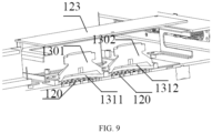
- the device 100 further includes loudspeakers 1301, 1302, which are arranged below the main board 123 and are fixed on the casing via adapter plates 1311, 1312, wherein a closed space is formed between an end face of the loudspeaker and a surface of the casing, and a sound outlet hole 120 is provided at the bottom of the housing.
- the adapter plate 1311 is fixed on the bottom surface of the housing and matches with the sound-outputting holes 120.
- the loudspeaker 1301 is fixed on the adapter plate 1311.
- the adapter plate 1311 is provided with a reserved hole with a size similar to that of the sound-emitting end face of the loudspeaker 1301.
- the sound-emitting end face of the loudspeaker 1301 is opposite to the sound-emitting hole of the housing through the reserved hole, so that the sound emitted by the loudspeaker 1301 can be emitted from the sound-emitting hole 120.
- the loudspeaker 1302 may be arranged in a manner similar to that of the loudspeaker 1301, and details are not repeatedly described herein.
- the material of the adapter plate can be an aluminium alloy material.
- the adapter plate not only achieves the effect of fixing, but also achieves the effect of gathering sounds, and can improve the effect of sound playing.
Landscapes
- Health & Medical Sciences (AREA)
- Surgery (AREA)
- Engineering & Computer Science (AREA)
- Life Sciences & Earth Sciences (AREA)
- Biomedical Technology (AREA)
- Public Health (AREA)
- Nuclear Medicine, Radiotherapy & Molecular Imaging (AREA)
- Veterinary Medicine (AREA)
- General Health & Medical Sciences (AREA)
- Heart & Thoracic Surgery (AREA)
- Medical Informatics (AREA)
- Molecular Biology (AREA)
- Animal Behavior & Ethology (AREA)
- Physics & Mathematics (AREA)
- Otolaryngology (AREA)
- Plasma & Fusion (AREA)
- Dentistry (AREA)
- Mechanical Engineering (AREA)
- Surgical Instruments (AREA)
Applications Claiming Priority (2)
| Application Number | Priority Date | Filing Date | Title |
|---|---|---|---|
| CN202111595350.3A CN114027937A (zh) | 2021-12-24 | 2021-12-24 | 向外科器械输出驱动信号的设备 |
| PCT/CN2022/141414 WO2023116881A1 (zh) | 2021-12-24 | 2022-12-23 | 向外科器械输出驱动信号的设备 |
Publications (2)
| Publication Number | Publication Date |
|---|---|
| EP4454576A1 true EP4454576A1 (de) | 2024-10-30 |
| EP4454576A4 EP4454576A4 (de) | 2025-12-31 |
Family
ID=80141120
Family Applications (1)
| Application Number | Title | Priority Date | Filing Date |
|---|---|---|---|
| EP22910192.8A Pending EP4454576A4 (de) | 2021-12-24 | 2022-12-23 | Vorrichtung zur ausgabe eines antriebssignals an ein chirurgisches instrument |
Country Status (4)
| Country | Link |
|---|---|
| US (1) | US20250127552A1 (de) |
| EP (1) | EP4454576A4 (de) |
| CN (1) | CN114027937A (de) |
| WO (1) | WO2023116881A1 (de) |
Families Citing this family (4)
| Publication number | Priority date | Publication date | Assignee | Title |
|---|---|---|---|---|
| CN114027937A (zh) * | 2021-12-24 | 2022-02-11 | 上海益超医疗器械有限公司 | 向外科器械输出驱动信号的设备 |
| CN116421296B (zh) * | 2022-12-29 | 2026-03-27 | 上海益超医疗器械有限公司 | 适用于超电混合能量平台的外科器械 |
| CN116602740A (zh) * | 2023-04-11 | 2023-08-18 | 青岛迈博思医疗科技有限公司 | 一种超声高频多能量输出系统 |
| EP4458300A1 (de) * | 2023-05-05 | 2024-11-06 | Erbe Elektromedizin GmbH | Elektrochirurgisches system und verfahren zu dessen betrieb |
Family Cites Families (27)
| Publication number | Priority date | Publication date | Assignee | Title |
|---|---|---|---|---|
| US4965532A (en) * | 1988-06-17 | 1990-10-23 | Olympus Optical Co., Ltd. | Circuit for driving ultrasonic transducer |
| GB9521772D0 (en) * | 1995-10-24 | 1996-01-03 | Gyrus Medical Ltd | An electrosurgical instrument |
| US5836943A (en) * | 1996-08-23 | 1998-11-17 | Team Medical, L.L.C. | Electrosurgical generator |
| US6033399A (en) * | 1997-04-09 | 2000-03-07 | Valleylab, Inc. | Electrosurgical generator with adaptive power control |
| US6480796B2 (en) * | 2000-10-20 | 2002-11-12 | Ethicon Endo-Surgery, Inc. | Method for improving the start up of an ultrasonic system under zero load conditions |
| US6776758B2 (en) * | 2002-10-11 | 2004-08-17 | Koninklijke Philips Electronics N.V. | RFI-protected ultrasound probe |
| JP2004222486A (ja) * | 2002-12-27 | 2004-08-05 | Murata Mfg Co Ltd | スイッチング電源モジュール |
| GB2416458B (en) * | 2004-07-20 | 2008-11-26 | Sra Dev Ltd | Ultrasonic generator system |
| US10039588B2 (en) * | 2009-12-16 | 2018-08-07 | Covidien Lp | System and method for tissue sealing |
| GB201303917D0 (en) * | 2013-03-05 | 2013-04-17 | Ezono Ag | System for image guided procedure |
| US10492850B2 (en) * | 2014-04-04 | 2019-12-03 | Covidien Lp | Systems and methods for calculating tissue impedance in electrosurgery |
| CN204734502U (zh) * | 2015-03-27 | 2015-11-04 | 无锡海斯凯尔医学技术有限公司 | 用于弹性测量的超声波探测便携装置 |
| US10898256B2 (en) * | 2015-06-30 | 2021-01-26 | Ethicon Llc | Surgical system with user adaptable techniques based on tissue impedance |
| CN205433883U (zh) * | 2016-01-25 | 2016-08-10 | 安进医疗科技(北京)有限公司 | 控制设备及电磁刀手术系统 |
| US10614949B2 (en) * | 2016-06-15 | 2020-04-07 | Covidien Lp | Electrostatic shielding of planar magnetic devices of electrosurgical generators |
| US11006997B2 (en) * | 2016-08-09 | 2021-05-18 | Covidien Lp | Ultrasonic and radiofrequency energy production and control from a single power converter |
| US11266455B2 (en) * | 2017-05-22 | 2022-03-08 | Cilag Gmbh International | Combination ultrasonic and electrosurgical instrument with a production clamp force based ultrasonic seal process and related methods |
| CN107648751B (zh) * | 2017-08-15 | 2024-06-04 | 安隽医疗科技(南京)有限公司 | 多功能智能信息化超声理疗仪 |
| US20190201042A1 (en) * | 2017-12-28 | 2019-07-04 | Ethicon Llc | Determining the state of an ultrasonic electromechanical system according to frequency shift |
| US12144136B2 (en) * | 2018-09-07 | 2024-11-12 | Cilag Gmbh International | Modular surgical energy system with module positional awareness with digital logic |
| CN109547220B (zh) * | 2018-12-14 | 2023-11-28 | 深圳和而泰智能控制股份有限公司 | 隔离通信电路 |
| CN110916762B (zh) * | 2019-07-01 | 2022-05-17 | 广州易和医疗技术开发有限公司 | 一种基于电阻网络的多输出微创手术系统 |
| CN211934284U (zh) * | 2019-08-13 | 2020-11-17 | 华南理工大学 | 一种具有超声和射频功能集成的微创手术发生装置 |
| CN113208697A (zh) * | 2021-03-26 | 2021-08-06 | 上海益超医疗器械有限公司 | 外科手术装置 |
| CN113648028A (zh) * | 2021-07-01 | 2021-11-16 | 深圳成川医疗有限公司 | 超声切割止血刀系统 |
| CN216876510U (zh) * | 2021-12-24 | 2022-07-05 | 上海益超医疗器械有限公司 | 向外科器械输出驱动信号的设备 |
| CN114027937A (zh) * | 2021-12-24 | 2022-02-11 | 上海益超医疗器械有限公司 | 向外科器械输出驱动信号的设备 |
-
2021
- 2021-12-24 CN CN202111595350.3A patent/CN114027937A/zh active Pending
-
2022
- 2022-12-23 EP EP22910192.8A patent/EP4454576A4/de active Pending
- 2022-12-23 US US18/719,266 patent/US20250127552A1/en active Pending
- 2022-12-23 WO PCT/CN2022/141414 patent/WO2023116881A1/zh not_active Ceased
Also Published As
| Publication number | Publication date |
|---|---|
| EP4454576A4 (de) | 2025-12-31 |
| CN114027937A (zh) | 2022-02-11 |
| WO2023116881A1 (zh) | 2023-06-29 |
| US20250127552A1 (en) | 2025-04-24 |
Similar Documents
| Publication | Publication Date | Title |
|---|---|---|
| EP4454576A1 (de) | Vorrichtung zur ausgabe eines antriebssignals an ein chirurgisches instrument | |
| AU2022371213B2 (en) | Ultrasonic scalpel, energy instrument for surgery, and power adjustment method therefor | |
| US20250017613A1 (en) | Device for outputting drive signals to surgical instrument, and surgical system | |
| JP5603173B2 (ja) | 電気外科発電機 | |
| JP4384271B2 (ja) | 超音波手術装置 | |
| CN216876510U (zh) | 向外科器械输出驱动信号的设备 | |
| WO2011052390A1 (ja) | 医療用装置 | |
| CN212515446U (zh) | 一种超声换能器控制装置 | |
| US20150305798A1 (en) | Portable electrosurgical instrument | |
| CN117137612A (zh) | 一种具有神经探测功能的低温凝切手术设备 | |
| CN217611276U (zh) | 向外科器械输出驱动信号的设备及外科手术系统 | |
| CN211409357U (zh) | 一种用于手术机器人的力信息反馈视听装置 | |
| CN116407217A (zh) | 多输出能量外科设备 | |
| KR102548546B1 (ko) | 외과 수술용 진동자 유닛 및 이를 구비한 초음파 및 고주파 복합 수술기 | |
| CN215937635U (zh) | 一种数字微创高频能量工作系统 | |
| CN203303059U (zh) | 耳鸣检测设备 | |
| CN107684456A (zh) | 一种手术机器人超声刀控制系统 | |
| CN219207265U (zh) | 一种高稳定性等离子电刀系统 | |
| CN218013899U (zh) | 超声波发生器频率自动跟踪系统 | |
| CN117243685A (zh) | 一种医用高频电源发生器及使用方法 | |
| RU2839580C2 (ru) | Ультразвуковой скальпель, электрохирургический инструмент и способ регулирования их мощности | |
| CN116725654A (zh) | 一种智能高频电刀控制系统 | |
| US20170231682A1 (en) | Surgical device with functional device | |
| CN205514944U (zh) | 基于多功能模块集成的手术平台 | |
| CN119326496A (zh) | 一种新型的等离子手术装置及控制方法 |
Legal Events
| Date | Code | Title | Description |
|---|---|---|---|
| STAA | Information on the status of an ep patent application or granted ep patent |
Free format text: STATUS: THE INTERNATIONAL PUBLICATION HAS BEEN MADE |
|
| PUAI | Public reference made under article 153(3) epc to a published international application that has entered the european phase |
Free format text: ORIGINAL CODE: 0009012 |
|
| STAA | Information on the status of an ep patent application or granted ep patent |
Free format text: STATUS: REQUEST FOR EXAMINATION WAS MADE |
|
| 17P | Request for examination filed |
Effective date: 20240628 |
|
| AK | Designated contracting states |
Kind code of ref document: A1 Designated state(s): AL AT BE BG CH CY CZ DE DK EE ES FI FR GB GR HR HU IE IS IT LI LT LU LV MC ME MK MT NL NO PL PT RO RS SE SI SK SM TR |
|
| DAV | Request for validation of the european patent (deleted) | ||
| DAX | Request for extension of the european patent (deleted) | ||
| A4 | Supplementary search report drawn up and despatched |
Effective date: 20251202 |
|
| RIC1 | Information provided on ipc code assigned before grant |
Ipc: A61B 17/32 20060101AFI20251126BHEP Ipc: A61B 18/12 20060101ALI20251126BHEP Ipc: A61B 18/14 20060101ALI20251126BHEP Ipc: A61B 18/00 20060101ALI20251126BHEP |