EP4454564B1 - Method of automatic qrs complex detection in electrocardiogram signal - Google Patents
Method of automatic qrs complex detection in electrocardiogram signal Download PDFInfo
- Publication number
- EP4454564B1 EP4454564B1 EP23180201.8A EP23180201A EP4454564B1 EP 4454564 B1 EP4454564 B1 EP 4454564B1 EP 23180201 A EP23180201 A EP 23180201A EP 4454564 B1 EP4454564 B1 EP 4454564B1
- Authority
- EP
- European Patent Office
- Prior art keywords
- module
- factor
- value
- ecg signal
- window
- Prior art date
- Legal status (The legal status is an assumption and is not a legal conclusion. Google has not performed a legal analysis and makes no representation as to the accuracy of the status listed.)
- Active
Links
Images

Classifications
-
- A—HUMAN NECESSITIES
- A61—MEDICAL OR VETERINARY SCIENCE; HYGIENE
- A61B—DIAGNOSIS; SURGERY; IDENTIFICATION
- A61B5/00—Measuring for diagnostic purposes; Identification of persons
- A61B5/24—Detecting, measuring or recording bioelectric or biomagnetic signals of the body or parts thereof
- A61B5/316—Modalities, i.e. specific diagnostic methods
- A61B5/318—Heart-related electrical modalities, e.g. electrocardiography [ECG]
- A61B5/346—Analysis of electrocardiograms
- A61B5/349—Detecting specific parameters of the electrocardiograph cycle
- A61B5/352—Detecting R peaks, e.g. for synchronising diagnostic apparatus; Estimating R-R interval
-
- A—HUMAN NECESSITIES
- A61—MEDICAL OR VETERINARY SCIENCE; HYGIENE
- A61B—DIAGNOSIS; SURGERY; IDENTIFICATION
- A61B5/00—Measuring for diagnostic purposes; Identification of persons
- A61B5/24—Detecting, measuring or recording bioelectric or biomagnetic signals of the body or parts thereof
- A61B5/316—Modalities, i.e. specific diagnostic methods
- A61B5/318—Heart-related electrical modalities, e.g. electrocardiography [ECG]
- A61B5/346—Analysis of electrocardiograms
-
- A—HUMAN NECESSITIES
- A61—MEDICAL OR VETERINARY SCIENCE; HYGIENE
- A61B—DIAGNOSIS; SURGERY; IDENTIFICATION
- A61B5/00—Measuring for diagnostic purposes; Identification of persons
- A61B5/24—Detecting, measuring or recording bioelectric or biomagnetic signals of the body or parts thereof
- A61B5/316—Modalities, i.e. specific diagnostic methods
- A61B5/318—Heart-related electrical modalities, e.g. electrocardiography [ECG]
- A61B5/346—Analysis of electrocardiograms
- A61B5/349—Detecting specific parameters of the electrocardiograph cycle
-
- A—HUMAN NECESSITIES
- A61—MEDICAL OR VETERINARY SCIENCE; HYGIENE
- A61B—DIAGNOSIS; SURGERY; IDENTIFICATION
- A61B5/00—Measuring for diagnostic purposes; Identification of persons
- A61B5/24—Detecting, measuring or recording bioelectric or biomagnetic signals of the body or parts thereof
- A61B5/316—Modalities, i.e. specific diagnostic methods
- A61B5/318—Heart-related electrical modalities, e.g. electrocardiography [ECG]
- A61B5/346—Analysis of electrocardiograms
- A61B5/349—Detecting specific parameters of the electrocardiograph cycle
- A61B5/366—Detecting abnormal QRS complex, e.g. widening
-
- A—HUMAN NECESSITIES
- A61—MEDICAL OR VETERINARY SCIENCE; HYGIENE
- A61B—DIAGNOSIS; SURGERY; IDENTIFICATION
- A61B5/00—Measuring for diagnostic purposes; Identification of persons
- A61B5/72—Signal processing specially adapted for physiological signals or for diagnostic purposes
- A61B5/7235—Details of waveform analysis
- A61B5/725—Details of waveform analysis using specific filters therefor, e.g. Kalman or adaptive filters
-
- G—PHYSICS
- G01—MEASURING; TESTING
- G01N—INVESTIGATING OR ANALYSING MATERIALS BY DETERMINING THEIR CHEMICAL OR PHYSICAL PROPERTIES
- G01N7/00—Analysing materials by measuring the pressure or volume of a gas or vapour
-
- A—HUMAN NECESSITIES
- A61—MEDICAL OR VETERINARY SCIENCE; HYGIENE
- A61B—DIAGNOSIS; SURGERY; IDENTIFICATION
- A61B5/00—Measuring for diagnostic purposes; Identification of persons
- A61B5/24—Detecting, measuring or recording bioelectric or biomagnetic signals of the body or parts thereof
- A61B5/30—Input circuits therefor
- A61B5/307—Input circuits therefor specially adapted for particular uses
- A61B5/308—Input circuits therefor specially adapted for particular uses for electrocardiography [ECG]
Definitions
- the subject of the invention is a method of automatic QRS complex detection in an electrocardiogram signal ECG applicable in biomedical diagnostics.
- Electrocardiography is one of the most commonly performed diagnostic procedures that allows the analysis and assessment of the heart's electrical activity. Reading the potential difference between two electrodes placed on the body of a patient, mostly on the chest, allows plotting the so-called electrocardiographic curve (ECG curve) representing the course of the mentioned potential difference over time. Evaluation of the ECG curve requires analysis to be made by a doctor or a specialist in order to detect possible irregularities of the heart activity of the examined person. In order to support the interpretation and evaluation of the ECG curve, many devices and algorithms have been developed that allow to at least partially automate the ECG curve analysis, increase its reliability and accelerate the diagnosis.
- the ECG curve is cyclical due to the repetitive activity of the heart.
- there are characteristic waveform features corresponding to cardiac activity which most often include the P-wave, the QRS complex and the T-wave.
- the P-wave corresponds to depolarization of the atrial muscle
- the QRS complex corresponds to depolarization of the ventricular muscle
- the T-wave corresponds to ventricular repolarization.
- the description of the heart's activity and the interpretation of the ECG curve is the subject of numerous studies available in the art.
- an ABS_DIFF_SHORT signal generated on an output of an ABS_DIFF_SHORT_MODULE module which is the difference of the current instantaneous value of the ECG signal provided by an ECG_MODULE measuring module, and the mean value of a SHORT_AVG of the ECG signal calculated for a time interval T_SHORT, are monitored using the COMP comparator.
- the COMP comparator detects the moment when an ABS_DIFF_SHORT signal reaches a threshold TH value previously determined with a TH_MODULE module, and then, when the ABS_DIFF_SHORT signal reaches the threshold TH value, the countdown of a SEARCHING_WINDOW time window starts with a PULSE_GENERATOR pulse generator which has fixed-length for search for a R wave in the QRS complex of the ECG signal.
- the maximum value of the ABS_DIFF_LONG_MODULE module produced at its output is recorded during the SEARCHING_WINDOW time window of the ABS_DIFF_LONG signal, which is the difference of the current instantaneous value of the ECG signal and the average LONG_AVG value of the ECG signal calculated for a segment of a T_LONG time segment while the PEAK_DETECTOR detection module the moment of the detected maximum value of the ABS_DIFF_LONG signal is recorded during the SEARCHING_WINDOW time window.
- the maximum value of the ABS_DIFF_LONG signal detected by the PEAK_DETECTOR detection module is stored by means of a R_AMPLITUDE_MEMORY memory module, which is considered to be the R-wave amplitude in the QRS complex.
- the object of the present invention is to provide an improved method of automatic QRS complex detection in an electrocardiogram signal with increased reliability of R-wave detection. This object is solved by the method according to claim 1.
- a method of automatic QRS complex detection in an electrocardiogram signal consists in receiving an ECG signal obtained by means of a measuring module ECG MODULE monitoring electrical heart activity of a patient, wherein the ECG signal is represented in the form of samples provided by the measuring module ECG MODULE at equal time intervals measured by a clock and successively stored in a buffer BUF by means of a CLK signal generated in the measuring module ECG MODULE, and then in that
- the local extremes of the ECG signal are searched for by means of the module EXTREMA MODULE in such a way that
- the value of the parameter FACTOR which specifies how distinct local extreme the considered sample of the ECG signal is against the neighbouring samples of the ECG signal, is determined by means of the module FACTOR MODULE in such a way that
- the method according to the invention provides increased reliability of detecting R-waves even in the presence of cardiac anomalies and in the presence of interference or distortion of the ECG signal.
- the features of the method furthermore make it possible to keep the computational complexity low, whereby the method can be implemented in portable devices, e.g. by implementing in the form of computer program instructions on a storage medium.
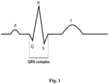
- Fig. 1 is a simplified diagram of an electrocardiogram signal waveform (ECG) with marked P- and T- waves and QRS complex.
- ECG electrocardiogram signal
- the ECG signal is received by means of a measuring module through electrodes placed on the body of a patient.
- the ECG signal is characterized by a sequence of positive and negative deviations (so-called waves) from the isoelectric line, which correspond to periods of time in which no cardiac excitation is found.
- the group of the largest waves includes a negative deflection (Q-wave), a positive deflection (R-wave) and again a negative deflection (S-wave) and is referred to as the so-called QRS complex.
- the greatest amplitude in the QRS complex usually has the R-wave, so that the detection of the QRS complex often comes down to detection of the R-wave.
- the statistics of time intervals between R-waves and of amplitudes of the R-waves is an important diagnostic information used in medicine, among others, to identify abnormalities in the heart activity.
- Fig. 2 is a block diagram of a device for automatic QRS complex detection in an electrocardiogram signal for implementing the method according to the present invention.
- the exemplary device for implementing the method according to the present invention comprises a number of mutually connected modules, which are used to implement particular steps of the method according to the invention.
- an output of a module ECG MODULE is connected to an input of a buffer module BUF, whose output is connected to an input of a module PREPROCESSING MODULE.
- Outputs of the module PREPROCESSING MODULE and of a module TH MODULE are connected to inputs of a comparator COMPARATOR, whose output is connected to a module SEARCHING WINDOW PULSE GENERATOR.
- Inputs of a module PEAK DETECTOR are connected to outputs of the modules PREPROCESSING MODULE and SEARCHING WINDOW PULSE GENERATOR, respectively, whereas its outputs are connected to inputs of modules REFRACTORY WINDOW PULSE GENERATOR and PEAK AMPLITUDE MEMORY, respectively.
- Inputs of a module PULSE EXTENSION are connected to outputs of the modules PROCESSING MODULE and PEAK AMPLITUDE MEMORY, respectively, whereas its output is connected to an input of the module SEARCHING WINDOW PULSE GENERATOR.
- Inputs of a module EXTREMA MODULE are connected to inputs of the modules BUF, REFRACTORY WINDOW PULSE GENERATOR, SEARCHING WINDOW PULSE GENERATOR, respectively, whereas its output is connected to an input of a module FACTOR MODULE.
- modules FACTOR MEMORY Particular inputs of a module FACTOR MEMORY are connected to outputs of modules REFRACTORY WINDOW PULSE GENERATOR, SEARCHING WINDOW PULSE GENERATOR and TH FACTOR MODULE, respectively.
- a module FACTOR SELECTOR has two inputs connected to the modules FACTOR MEMORY and SEARCHING WINDOW PULSE GENERATOR, respectively, and two outputs connected to modules TIMESTAMP MEMORY and AMPLITUDE MEMORY, whose outputs are connected to inputs of a module OUTPUT MEMORY.
- the output of the module AMPLITUDE MEMORY is also connected to an input of the module TH FACTOR MODULE.
- the measuring module ECG MODULE provides an electrocardiogram signal (ECG) in the form of signal samples, which are delivered at a given frequency determined by a signal CLK, which frequency in the embodiment is 360Hz.
- ECG electrocardiogram signal
- an initial value of a threshold TH_PREPROCESSED is set, equal to a maximum value of a signal Y_ PREPROCESSED detected within first 3 seconds of the ECG signal obtained by means of the measuring module ECG MODULE
- MIN_TH_FACTOR 1.22 [mV].
- the resolution of the A/D converter is 5 ⁇ V.
- a value of a parameter FACTOR is determined for this sample of the ECG signal by means of the module FACTOR MODULE, which parameter specifies how distinct local extreme the considered sample of the ECG signal is against the neighbouring samples of the ECG signal, and for this purpose the parameter FACTOR is assigned a value the bigger, the greater the amplitude of the considered local extreme represented by the considered sample of the ECG signal than the values of the neighbouring samples of the ECG signal.
- the determined value of the parameter FACTOR is compared with the threshold TH_FACTOR previously determined by means of the module TH FACTOR MODULE, and if the value of the parameter FACTOR is greater than the set threshold TH_FACTOR, the value of the parameter FACTOR and the time instant of receiving the considered sample of the ECG signal previously registered by means of the module EXTREMA MODULE, for which time instant the parameter FACTOR has been determined, are stored in a list THRESHOLD_WINDOW_LIST in a memory of the module FACTOR MEMORY, wherein these operations are repeated the required number of times until a time instant of reaching the threshold TH_PREPROCESSED by the signal Y_PREPROCESSED is detected by means of the comparator COMPARATOR, whose value is systematically decreased every sampling interval of the ECG signal (1/360 s) by successive multiplying the value of the comparator COMPARATOR, whose value is systematically decreased every sampling interval of the ECG signal (1/360 s) by successive multiplying
- a time instant of occurrence of the maximum value FACTOR_MAX1 of the parameter FACTOR is stored in the module TIMESTAMP MEMORY, which is also recognized as the time instant of occurrence of the R-wave in the QRS complex, and then the time instant of occurrence of the maximum value FACTOR_MAX1 of the parameter FACTOR is copied to the output memory module OUTPUT MEMORY.
- a time instant of occurrence of the maximum value FACTOR_MAX2 of the parameter FACTOR is stored in the module TIMESTAMP MEMORY, which is also recognized as the time instant of occurrence of the previous R-wave in the QRS complex, than the R-wave previously detected for the value FACTOR_MAX1 of the parameter FACTOR, and then the time instant of occurrence of the maximum value FACTOR_MAX2 of the parameter FACTOR is copied to the output memory module OUTPUT MEMORY.
- the value of the parameter FACTOR which specifies how distinct local extreme the considered sample of the ECG signal is against the neighbouring samples of the ECG signal, is determined by means of the module FACTOR MODULE in such a way that
Landscapes
- Health & Medical Sciences (AREA)
- Life Sciences & Earth Sciences (AREA)
- Cardiology (AREA)
- Engineering & Computer Science (AREA)
- Pathology (AREA)
- Physics & Mathematics (AREA)
- General Health & Medical Sciences (AREA)
- Heart & Thoracic Surgery (AREA)
- Veterinary Medicine (AREA)
- Public Health (AREA)
- Animal Behavior & Ethology (AREA)
- Biophysics (AREA)
- Surgery (AREA)
- Biomedical Technology (AREA)
- Molecular Biology (AREA)
- Medical Informatics (AREA)
- Analytical Chemistry (AREA)
- Biochemistry (AREA)
- Chemical & Material Sciences (AREA)
- General Physics & Mathematics (AREA)
- Immunology (AREA)
- Artificial Intelligence (AREA)
- Computer Vision & Pattern Recognition (AREA)
- Physiology (AREA)
- Psychiatry (AREA)
- Signal Processing (AREA)
- Measurement And Recording Of Electrical Phenomena And Electrical Characteristics Of The Living Body (AREA)
Applications Claiming Priority (1)
| Application Number | Priority Date | Filing Date | Title |
|---|---|---|---|
| PL444668A PL444668A1 (pl) | 2023-04-28 | 2023-04-28 | Sposób automatycznej detekcji zespołu QRS w sygnale elektrokardiogramu |
Publications (3)
| Publication Number | Publication Date |
|---|---|
| EP4454564A1 EP4454564A1 (en) | 2024-10-30 |
| EP4454564C0 EP4454564C0 (en) | 2025-04-30 |
| EP4454564B1 true EP4454564B1 (en) | 2025-04-30 |
Family
ID=87580166
Family Applications (1)
| Application Number | Title | Priority Date | Filing Date |
|---|---|---|---|
| EP23180201.8A Active EP4454564B1 (en) | 2023-04-28 | 2023-06-20 | Method of automatic qrs complex detection in electrocardiogram signal |
Country Status (2)
| Country | Link |
|---|---|
| EP (1) | EP4454564B1 (pl) |
| PL (2) | PL444668A1 (pl) |
Family Cites Families (1)
| Publication number | Priority date | Publication date | Assignee | Title |
|---|---|---|---|---|
| PL241615B1 (pl) * | 2020-09-22 | 2022-11-07 | Akademia Gorniczo Hutnicza Im Stanislawa Staszica W Krakowie | Sposób detekcji zespołu QRS w sygnale elektrokardiogramu |
-
2023
- 2023-04-28 PL PL444668A patent/PL444668A1/pl unknown
- 2023-06-20 EP EP23180201.8A patent/EP4454564B1/en active Active
- 2023-06-20 PL PL23180201.8T patent/PL4454564T3/pl unknown
Also Published As
| Publication number | Publication date |
|---|---|
| EP4454564C0 (en) | 2025-04-30 |
| PL444668A1 (pl) | 2024-11-04 |
| EP4454564A1 (en) | 2024-10-30 |
| PL4454564T3 (pl) | 2025-08-04 |
Similar Documents
| Publication | Publication Date | Title |
|---|---|---|
| JP4768095B2 (ja) | 心臓機能を表す信号の特性を決定するシステム | |
| US8755876B2 (en) | Methods and systems for atrial fibrillation detection | |
| US4492235A (en) | System and method for predicting ventricular tachycardia by derivative analysis | |
| US5827196A (en) | Method and system for providing characterizations of waveform representations of heart function | |
| US4181135A (en) | Method and apparatus for monitoring electrocardiographic waveforms | |
| US8024030B2 (en) | System and method for analyzing an electrocardiogram signal | |
| Ajdaraga et al. | Analysis of sampling frequency and resolution in ECG signals | |
| US6668189B2 (en) | Method and system for measuring T-wave alternans by alignment of alternating median beats to a cubic spline | |
| JPS5937107B2 (ja) | 心電計コンピユ−タ | |
| EP3970615B1 (en) | Method for detecting qrs complex of electrocardiogram signal | |
| JPH0211120A (ja) | 時変信号の波形部分を比較するための方法および装置 | |
| US20170281021A1 (en) | Heartbeat detection method and heartbeat detection device | |
| US20190374123A1 (en) | Predicting atrial fibrillation or stroke using p-wave analysis | |
| JP2023532510A (ja) | ペーシングパルス検出およびペーシングアーチファクト除去のための方法およびシステム | |
| JPH10211180A (ja) | 心臓機能自動診断方法 | |
| EP2928363B1 (en) | Apparatus and method for determining the occurrence of a qrs complex in ecg data | |
| EP4454564B1 (en) | Method of automatic qrs complex detection in electrocardiogram signal | |
| EP4454565B1 (en) | Device for automatic qrs complex detection in electrocardiogram signal | |
| CN115770054A (zh) | 心电信号处理方法、便携式心电采集设备和存储介质 | |
| Palaniappan et al. | R-peak detection using altered pan-Tompkins algorithm | |
| EP3970616B1 (en) | A device for detecting the qrs complex of electrocardiogram signal | |
| WO1984003032A1 (en) | System and method for predicting ventricular tachycardia | |
| Mincholé et al. | Evaluation of a root mean squared based ischemia detector on the long-term ST database with body position change cancellation | |
| RU2371087C1 (ru) | Способ выявления альтернаций т-зубца электрокардиосигнала в режиме реального времени и устройство для его осуществления | |
| EP3782540A1 (en) | Method for determining r peaks of electrocardiogram |
Legal Events
| Date | Code | Title | Description |
|---|---|---|---|
| PUAI | Public reference made under article 153(3) epc to a published international application that has entered the european phase |
Free format text: ORIGINAL CODE: 0009012 |
|
| STAA | Information on the status of an ep patent application or granted ep patent |
Free format text: STATUS: THE APPLICATION HAS BEEN PUBLISHED |
|
| AK | Designated contracting states |
Kind code of ref document: A1 Designated state(s): AL AT BE BG CH CY CZ DE DK EE ES FI FR GB GR HR HU IE IS IT LI LT LU LV MC ME MK MT NL NO PL PT RO RS SE SI SK SM TR |
|
| STAA | Information on the status of an ep patent application or granted ep patent |
Free format text: STATUS: REQUEST FOR EXAMINATION WAS MADE |
|
| 17P | Request for examination filed |
Effective date: 20241118 |
|
| RBV | Designated contracting states (corrected) |
Designated state(s): AL AT BE BG CH CY CZ DE DK EE ES FI FR GB GR HR HU IE IS IT LI LT LU LV MC ME MK MT NL NO PL PT RO RS SE SI SK SM TR |
|
| GRAP | Despatch of communication of intention to grant a patent |
Free format text: ORIGINAL CODE: EPIDOSNIGR1 |
|
| STAA | Information on the status of an ep patent application or granted ep patent |
Free format text: STATUS: GRANT OF PATENT IS INTENDED |
|
| RIC1 | Information provided on ipc code assigned before grant |
Ipc: A61B 5/00 20060101ALI20250204BHEP Ipc: A61B 5/366 20210101ALI20250204BHEP Ipc: A61B 5/352 20210101AFI20250204BHEP |
|
| INTG | Intention to grant announced |
Effective date: 20250213 |
|
| GRAS | Grant fee paid |
Free format text: ORIGINAL CODE: EPIDOSNIGR3 |
|
| GRAA | (expected) grant |
Free format text: ORIGINAL CODE: 0009210 |
|
| STAA | Information on the status of an ep patent application or granted ep patent |
Free format text: STATUS: THE PATENT HAS BEEN GRANTED |
|
| AK | Designated contracting states |
Kind code of ref document: B1 Designated state(s): AL AT BE BG CH CY CZ DE DK EE ES FI FR GB GR HR HU IE IS IT LI LT LU LV MC ME MK MT NL NO PL PT RO RS SE SI SK SM TR |
|
| REG | Reference to a national code |
Ref country code: CH Ref legal event code: EP Ref country code: GB Ref legal event code: FG4D |
|
| REG | Reference to a national code |
Ref country code: DE Ref legal event code: R096 Ref document number: 602023003147 Country of ref document: DE |
|
| REG | Reference to a national code |
Ref country code: IE Ref legal event code: FG4D |
|
| U01 | Request for unitary effect filed |
Effective date: 20250505 |
|
| U07 | Unitary effect registered |
Designated state(s): AT BE BG DE DK EE FI FR IT LT LU LV MT NL PT RO SE SI Effective date: 20250509 |
|
| U20 | Renewal fee for the european patent with unitary effect paid |
Year of fee payment: 3 Effective date: 20250611 |
|
| PG25 | Lapsed in a contracting state [announced via postgrant information from national office to epo] |
Ref country code: ES Free format text: LAPSE BECAUSE OF FAILURE TO SUBMIT A TRANSLATION OF THE DESCRIPTION OR TO PAY THE FEE WITHIN THE PRESCRIBED TIME-LIMIT Effective date: 20250430 |
|
| PG25 | Lapsed in a contracting state [announced via postgrant information from national office to epo] |
Ref country code: NO Free format text: LAPSE BECAUSE OF FAILURE TO SUBMIT A TRANSLATION OF THE DESCRIPTION OR TO PAY THE FEE WITHIN THE PRESCRIBED TIME-LIMIT Effective date: 20250730 Ref country code: GR Free format text: LAPSE BECAUSE OF FAILURE TO SUBMIT A TRANSLATION OF THE DESCRIPTION OR TO PAY THE FEE WITHIN THE PRESCRIBED TIME-LIMIT Effective date: 20250731 |
|
| PG25 | Lapsed in a contracting state [announced via postgrant information from national office to epo] |
Ref country code: HR Free format text: LAPSE BECAUSE OF FAILURE TO SUBMIT A TRANSLATION OF THE DESCRIPTION OR TO PAY THE FEE WITHIN THE PRESCRIBED TIME-LIMIT Effective date: 20250430 |
|
| PG25 | Lapsed in a contracting state [announced via postgrant information from national office to epo] |
Ref country code: RS Free format text: LAPSE BECAUSE OF FAILURE TO SUBMIT A TRANSLATION OF THE DESCRIPTION OR TO PAY THE FEE WITHIN THE PRESCRIBED TIME-LIMIT Effective date: 20250731 |
|
| PG25 | Lapsed in a contracting state [announced via postgrant information from national office to epo] |
Ref country code: IS Free format text: LAPSE BECAUSE OF FAILURE TO SUBMIT A TRANSLATION OF THE DESCRIPTION OR TO PAY THE FEE WITHIN THE PRESCRIBED TIME-LIMIT Effective date: 20250830 |
|
| PG25 | Lapsed in a contracting state [announced via postgrant information from national office to epo] |
Ref country code: SM Free format text: LAPSE BECAUSE OF FAILURE TO SUBMIT A TRANSLATION OF THE DESCRIPTION OR TO PAY THE FEE WITHIN THE PRESCRIBED TIME-LIMIT Effective date: 20250430 |
|
| PG25 | Lapsed in a contracting state [announced via postgrant information from national office to epo] |
Ref country code: CZ Free format text: LAPSE BECAUSE OF FAILURE TO SUBMIT A TRANSLATION OF THE DESCRIPTION OR TO PAY THE FEE WITHIN THE PRESCRIBED TIME-LIMIT Effective date: 20250430 |
|
| PG25 | Lapsed in a contracting state [announced via postgrant information from national office to epo] |
Ref country code: SK Free format text: LAPSE BECAUSE OF FAILURE TO SUBMIT A TRANSLATION OF THE DESCRIPTION OR TO PAY THE FEE WITHIN THE PRESCRIBED TIME-LIMIT Effective date: 20250430 |
|
| PG25 | Lapsed in a contracting state [announced via postgrant information from national office to epo] |
Ref country code: MC Free format text: LAPSE BECAUSE OF FAILURE TO SUBMIT A TRANSLATION OF THE DESCRIPTION OR TO PAY THE FEE WITHIN THE PRESCRIBED TIME-LIMIT Effective date: 20250430 |
|
| PLBE | No opposition filed within time limit |
Free format text: ORIGINAL CODE: 0009261 |
|
| STAA | Information on the status of an ep patent application or granted ep patent |
Free format text: STATUS: NO OPPOSITION FILED WITHIN TIME LIMIT |
|
| REG | Reference to a national code |
Ref country code: CH Ref legal event code: L10 Free format text: ST27 STATUS EVENT CODE: U-0-0-L10-L00 (AS PROVIDED BY THE NATIONAL OFFICE) Effective date: 20260311 |
|
| 26N | No opposition filed |
Effective date: 20260202 |
|
| PG25 | Lapsed in a contracting state [announced via postgrant information from national office to epo] |
Ref country code: IE Free format text: LAPSE BECAUSE OF NON-PAYMENT OF DUE FEES Effective date: 20250620 |