EP4454564B1 - Verfahren zur automatischen qrs-komplex-detektion in einem elektrokardiogrammsignal - Google Patents
Verfahren zur automatischen qrs-komplex-detektion in einem elektrokardiogrammsignal Download PDFInfo
- Publication number
- EP4454564B1 EP4454564B1 EP23180201.8A EP23180201A EP4454564B1 EP 4454564 B1 EP4454564 B1 EP 4454564B1 EP 23180201 A EP23180201 A EP 23180201A EP 4454564 B1 EP4454564 B1 EP 4454564B1
- Authority
- EP
- European Patent Office
- Prior art keywords
- module
- factor
- value
- ecg signal
- window
- Prior art date
- Legal status (The legal status is an assumption and is not a legal conclusion. Google has not performed a legal analysis and makes no representation as to the accuracy of the status listed.)
- Active
Links
Images

Classifications
-
- A—HUMAN NECESSITIES
- A61—MEDICAL OR VETERINARY SCIENCE; HYGIENE
- A61B—DIAGNOSIS; SURGERY; IDENTIFICATION
- A61B5/00—Measuring for diagnostic purposes; Identification of persons
- A61B5/24—Detecting, measuring or recording bioelectric or biomagnetic signals of the body or parts thereof
- A61B5/316—Modalities, i.e. specific diagnostic methods
- A61B5/318—Heart-related electrical modalities, e.g. electrocardiography [ECG]
- A61B5/346—Analysis of electrocardiograms
- A61B5/349—Detecting specific parameters of the electrocardiograph cycle
- A61B5/352—Detecting R peaks, e.g. for synchronising diagnostic apparatus; Estimating R-R interval
-
- A—HUMAN NECESSITIES
- A61—MEDICAL OR VETERINARY SCIENCE; HYGIENE
- A61B—DIAGNOSIS; SURGERY; IDENTIFICATION
- A61B5/00—Measuring for diagnostic purposes; Identification of persons
- A61B5/24—Detecting, measuring or recording bioelectric or biomagnetic signals of the body or parts thereof
- A61B5/316—Modalities, i.e. specific diagnostic methods
- A61B5/318—Heart-related electrical modalities, e.g. electrocardiography [ECG]
- A61B5/346—Analysis of electrocardiograms
-
- A—HUMAN NECESSITIES
- A61—MEDICAL OR VETERINARY SCIENCE; HYGIENE
- A61B—DIAGNOSIS; SURGERY; IDENTIFICATION
- A61B5/00—Measuring for diagnostic purposes; Identification of persons
- A61B5/24—Detecting, measuring or recording bioelectric or biomagnetic signals of the body or parts thereof
- A61B5/316—Modalities, i.e. specific diagnostic methods
- A61B5/318—Heart-related electrical modalities, e.g. electrocardiography [ECG]
- A61B5/346—Analysis of electrocardiograms
- A61B5/349—Detecting specific parameters of the electrocardiograph cycle
-
- A—HUMAN NECESSITIES
- A61—MEDICAL OR VETERINARY SCIENCE; HYGIENE
- A61B—DIAGNOSIS; SURGERY; IDENTIFICATION
- A61B5/00—Measuring for diagnostic purposes; Identification of persons
- A61B5/24—Detecting, measuring or recording bioelectric or biomagnetic signals of the body or parts thereof
- A61B5/316—Modalities, i.e. specific diagnostic methods
- A61B5/318—Heart-related electrical modalities, e.g. electrocardiography [ECG]
- A61B5/346—Analysis of electrocardiograms
- A61B5/349—Detecting specific parameters of the electrocardiograph cycle
- A61B5/366—Detecting abnormal QRS complex, e.g. widening
-
- A—HUMAN NECESSITIES
- A61—MEDICAL OR VETERINARY SCIENCE; HYGIENE
- A61B—DIAGNOSIS; SURGERY; IDENTIFICATION
- A61B5/00—Measuring for diagnostic purposes; Identification of persons
- A61B5/72—Signal processing specially adapted for physiological signals or for diagnostic purposes
- A61B5/7235—Details of waveform analysis
- A61B5/725—Details of waveform analysis using specific filters therefor, e.g. Kalman or adaptive filters
-
- G—PHYSICS
- G01—MEASURING; TESTING
- G01N—INVESTIGATING OR ANALYSING MATERIALS BY DETERMINING THEIR CHEMICAL OR PHYSICAL PROPERTIES
- G01N7/00—Analysing materials by measuring the pressure or volume of a gas or vapour
-
- A—HUMAN NECESSITIES
- A61—MEDICAL OR VETERINARY SCIENCE; HYGIENE
- A61B—DIAGNOSIS; SURGERY; IDENTIFICATION
- A61B5/00—Measuring for diagnostic purposes; Identification of persons
- A61B5/24—Detecting, measuring or recording bioelectric or biomagnetic signals of the body or parts thereof
- A61B5/30—Input circuits therefor
- A61B5/307—Input circuits therefor specially adapted for particular uses
- A61B5/308—Input circuits therefor specially adapted for particular uses for electrocardiography [ECG]
Definitions
- the subject of the invention is a method of automatic QRS complex detection in an electrocardiogram signal ECG applicable in biomedical diagnostics.
- Electrocardiography is one of the most commonly performed diagnostic procedures that allows the analysis and assessment of the heart's electrical activity. Reading the potential difference between two electrodes placed on the body of a patient, mostly on the chest, allows plotting the so-called electrocardiographic curve (ECG curve) representing the course of the mentioned potential difference over time. Evaluation of the ECG curve requires analysis to be made by a doctor or a specialist in order to detect possible irregularities of the heart activity of the examined person. In order to support the interpretation and evaluation of the ECG curve, many devices and algorithms have been developed that allow to at least partially automate the ECG curve analysis, increase its reliability and accelerate the diagnosis.
- the ECG curve is cyclical due to the repetitive activity of the heart.
- there are characteristic waveform features corresponding to cardiac activity which most often include the P-wave, the QRS complex and the T-wave.
- the P-wave corresponds to depolarization of the atrial muscle
- the QRS complex corresponds to depolarization of the ventricular muscle
- the T-wave corresponds to ventricular repolarization.
- the description of the heart's activity and the interpretation of the ECG curve is the subject of numerous studies available in the art.
- an ABS_DIFF_SHORT signal generated on an output of an ABS_DIFF_SHORT_MODULE module which is the difference of the current instantaneous value of the ECG signal provided by an ECG_MODULE measuring module, and the mean value of a SHORT_AVG of the ECG signal calculated for a time interval T_SHORT, are monitored using the COMP comparator.
- the COMP comparator detects the moment when an ABS_DIFF_SHORT signal reaches a threshold TH value previously determined with a TH_MODULE module, and then, when the ABS_DIFF_SHORT signal reaches the threshold TH value, the countdown of a SEARCHING_WINDOW time window starts with a PULSE_GENERATOR pulse generator which has fixed-length for search for a R wave in the QRS complex of the ECG signal.
- the maximum value of the ABS_DIFF_LONG_MODULE module produced at its output is recorded during the SEARCHING_WINDOW time window of the ABS_DIFF_LONG signal, which is the difference of the current instantaneous value of the ECG signal and the average LONG_AVG value of the ECG signal calculated for a segment of a T_LONG time segment while the PEAK_DETECTOR detection module the moment of the detected maximum value of the ABS_DIFF_LONG signal is recorded during the SEARCHING_WINDOW time window.
- the maximum value of the ABS_DIFF_LONG signal detected by the PEAK_DETECTOR detection module is stored by means of a R_AMPLITUDE_MEMORY memory module, which is considered to be the R-wave amplitude in the QRS complex.
- the object of the present invention is to provide an improved method of automatic QRS complex detection in an electrocardiogram signal with increased reliability of R-wave detection. This object is solved by the method according to claim 1.
- a method of automatic QRS complex detection in an electrocardiogram signal consists in receiving an ECG signal obtained by means of a measuring module ECG MODULE monitoring electrical heart activity of a patient, wherein the ECG signal is represented in the form of samples provided by the measuring module ECG MODULE at equal time intervals measured by a clock and successively stored in a buffer BUF by means of a CLK signal generated in the measuring module ECG MODULE, and then in that
- the local extremes of the ECG signal are searched for by means of the module EXTREMA MODULE in such a way that
- the value of the parameter FACTOR which specifies how distinct local extreme the considered sample of the ECG signal is against the neighbouring samples of the ECG signal, is determined by means of the module FACTOR MODULE in such a way that
- the method according to the invention provides increased reliability of detecting R-waves even in the presence of cardiac anomalies and in the presence of interference or distortion of the ECG signal.
- the features of the method furthermore make it possible to keep the computational complexity low, whereby the method can be implemented in portable devices, e.g. by implementing in the form of computer program instructions on a storage medium.
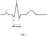
- Fig. 1 is a simplified diagram of an electrocardiogram signal waveform (ECG) with marked P- and T- waves and QRS complex.
- ECG electrocardiogram signal
- the ECG signal is received by means of a measuring module through electrodes placed on the body of a patient.
- the ECG signal is characterized by a sequence of positive and negative deviations (so-called waves) from the isoelectric line, which correspond to periods of time in which no cardiac excitation is found.
- the group of the largest waves includes a negative deflection (Q-wave), a positive deflection (R-wave) and again a negative deflection (S-wave) and is referred to as the so-called QRS complex.
- the greatest amplitude in the QRS complex usually has the R-wave, so that the detection of the QRS complex often comes down to detection of the R-wave.
- the statistics of time intervals between R-waves and of amplitudes of the R-waves is an important diagnostic information used in medicine, among others, to identify abnormalities in the heart activity.
- Fig. 2 is a block diagram of a device for automatic QRS complex detection in an electrocardiogram signal for implementing the method according to the present invention.
- the exemplary device for implementing the method according to the present invention comprises a number of mutually connected modules, which are used to implement particular steps of the method according to the invention.
- an output of a module ECG MODULE is connected to an input of a buffer module BUF, whose output is connected to an input of a module PREPROCESSING MODULE.
- Outputs of the module PREPROCESSING MODULE and of a module TH MODULE are connected to inputs of a comparator COMPARATOR, whose output is connected to a module SEARCHING WINDOW PULSE GENERATOR.
- Inputs of a module PEAK DETECTOR are connected to outputs of the modules PREPROCESSING MODULE and SEARCHING WINDOW PULSE GENERATOR, respectively, whereas its outputs are connected to inputs of modules REFRACTORY WINDOW PULSE GENERATOR and PEAK AMPLITUDE MEMORY, respectively.
- Inputs of a module PULSE EXTENSION are connected to outputs of the modules PROCESSING MODULE and PEAK AMPLITUDE MEMORY, respectively, whereas its output is connected to an input of the module SEARCHING WINDOW PULSE GENERATOR.
- Inputs of a module EXTREMA MODULE are connected to inputs of the modules BUF, REFRACTORY WINDOW PULSE GENERATOR, SEARCHING WINDOW PULSE GENERATOR, respectively, whereas its output is connected to an input of a module FACTOR MODULE.
- modules FACTOR MEMORY Particular inputs of a module FACTOR MEMORY are connected to outputs of modules REFRACTORY WINDOW PULSE GENERATOR, SEARCHING WINDOW PULSE GENERATOR and TH FACTOR MODULE, respectively.
- a module FACTOR SELECTOR has two inputs connected to the modules FACTOR MEMORY and SEARCHING WINDOW PULSE GENERATOR, respectively, and two outputs connected to modules TIMESTAMP MEMORY and AMPLITUDE MEMORY, whose outputs are connected to inputs of a module OUTPUT MEMORY.
- the output of the module AMPLITUDE MEMORY is also connected to an input of the module TH FACTOR MODULE.
- the measuring module ECG MODULE provides an electrocardiogram signal (ECG) in the form of signal samples, which are delivered at a given frequency determined by a signal CLK, which frequency in the embodiment is 360Hz.
- ECG electrocardiogram signal
- an initial value of a threshold TH_PREPROCESSED is set, equal to a maximum value of a signal Y_ PREPROCESSED detected within first 3 seconds of the ECG signal obtained by means of the measuring module ECG MODULE
- MIN_TH_FACTOR 1.22 [mV].
- the resolution of the A/D converter is 5 ⁇ V.
- a value of a parameter FACTOR is determined for this sample of the ECG signal by means of the module FACTOR MODULE, which parameter specifies how distinct local extreme the considered sample of the ECG signal is against the neighbouring samples of the ECG signal, and for this purpose the parameter FACTOR is assigned a value the bigger, the greater the amplitude of the considered local extreme represented by the considered sample of the ECG signal than the values of the neighbouring samples of the ECG signal.
- the determined value of the parameter FACTOR is compared with the threshold TH_FACTOR previously determined by means of the module TH FACTOR MODULE, and if the value of the parameter FACTOR is greater than the set threshold TH_FACTOR, the value of the parameter FACTOR and the time instant of receiving the considered sample of the ECG signal previously registered by means of the module EXTREMA MODULE, for which time instant the parameter FACTOR has been determined, are stored in a list THRESHOLD_WINDOW_LIST in a memory of the module FACTOR MEMORY, wherein these operations are repeated the required number of times until a time instant of reaching the threshold TH_PREPROCESSED by the signal Y_PREPROCESSED is detected by means of the comparator COMPARATOR, whose value is systematically decreased every sampling interval of the ECG signal (1/360 s) by successive multiplying the value of the comparator COMPARATOR, whose value is systematically decreased every sampling interval of the ECG signal (1/360 s) by successive multiplying
- a time instant of occurrence of the maximum value FACTOR_MAX1 of the parameter FACTOR is stored in the module TIMESTAMP MEMORY, which is also recognized as the time instant of occurrence of the R-wave in the QRS complex, and then the time instant of occurrence of the maximum value FACTOR_MAX1 of the parameter FACTOR is copied to the output memory module OUTPUT MEMORY.
- a time instant of occurrence of the maximum value FACTOR_MAX2 of the parameter FACTOR is stored in the module TIMESTAMP MEMORY, which is also recognized as the time instant of occurrence of the previous R-wave in the QRS complex, than the R-wave previously detected for the value FACTOR_MAX1 of the parameter FACTOR, and then the time instant of occurrence of the maximum value FACTOR_MAX2 of the parameter FACTOR is copied to the output memory module OUTPUT MEMORY.
- the value of the parameter FACTOR which specifies how distinct local extreme the considered sample of the ECG signal is against the neighbouring samples of the ECG signal, is determined by means of the module FACTOR MODULE in such a way that
Landscapes
- Health & Medical Sciences (AREA)
- Life Sciences & Earth Sciences (AREA)
- Cardiology (AREA)
- Engineering & Computer Science (AREA)
- Pathology (AREA)
- Physics & Mathematics (AREA)
- General Health & Medical Sciences (AREA)
- Heart & Thoracic Surgery (AREA)
- Veterinary Medicine (AREA)
- Public Health (AREA)
- Animal Behavior & Ethology (AREA)
- Biophysics (AREA)
- Surgery (AREA)
- Biomedical Technology (AREA)
- Molecular Biology (AREA)
- Medical Informatics (AREA)
- Analytical Chemistry (AREA)
- Biochemistry (AREA)
- Chemical & Material Sciences (AREA)
- General Physics & Mathematics (AREA)
- Immunology (AREA)
- Artificial Intelligence (AREA)
- Computer Vision & Pattern Recognition (AREA)
- Physiology (AREA)
- Psychiatry (AREA)
- Signal Processing (AREA)
- Measurement And Recording Of Electrical Phenomena And Electrical Characteristics Of The Living Body (AREA)
Claims (4)
- Ein Verfahren zur Erkennung des QRS-Komplexes in einem Elektrokardiogrammsignal (EKG), das darin besteht, das EKG-Signal zu empfangen, das mittels eines Messmoduls ECG MODULE erhalten wurde, das die elektrische Herzaktivität eines Patienten überwacht, wobei das EKG-Signal in Form von Proben dargestellt wird, die vom Messmodul ECG MODULE in gleichen Zeitintervallen bereitgestellt werden, die von einer Uhr gemessen und nacheinander in einem Puffer BUF mittels eines im Messmodul ECG MODULE erzeugten CLK-Signals gespeichert werden, und dann dadurch, dassa) mittels eines Moduls TH MODULE ein Anfangswert eines Schwellenwerts TH_PREPROCESSED festgelegt wird, und dannb) ein an einem Ausgang eines Moduls PREPROCESSING MODULE erzeugtes Signal Y_PREPROCESSED mittels eines Komparators COMPARATOR überwacht wird, wobei dieses Signal erhalten wird, indemmittels des Moduls PREPROCESSING MODULE ein Signal Y0 erzeugt wird, das die Differenz zwischen einem Wert Y der betrachteten Probe des EKG-Signals und einem zuvor im Puffer BUF gespeicherten Probenwert des EKG-Signals ist, das eine vorgegebene Anzahl Nd von Proben zuvor empfangen wurde,und Bestimmen eines Signals Y1 mittels des Moduls PREPROCESSING MODULE, das die Summe der betrachteten Probe des Signals Y0 und eines Werts einer vorgegebenen Anzahl N-1 von Proben des Signals Y0 ist, die der betrachteten Probe des Signals Y0 unmittelbar vorausgehen, und Teilen dieser Summe durch eine Zahl N und Quadrieren dieser erhaltenen Zahl,c) mittels des Moduls TH MODULE der Wert des Schwellenwerts TH_PREPROCESSED in jedem Abtastintervall des EKG-Signals systematisch verringert wird, ausgehend von seinem Anfangswert, der zuvor mittels des Moduls TH MODULE bestimmt wurde, indem der aktuelle Schwellenwert TH_PREPROCESSED in Zeitpunkten des Empfangs aufeinanderfolgender Proben des EKG-Signals mit einem vorgegebenen und kleiner als eins konstanten Wert TH_REDUCING_FACTOR multipliziert wird, und diese Vorgänge das erforderliche Vielfache wiederholt werden, bis ein Zeitpunkt des Erreichens des Schwellenwerts TH_PREPROCESSED durch das Signal Y_PREPROCESSED mittels des Komparators COMPARATOR erkannt wird,d) wenn der Zeitpunkt des Erreichens des aktuellen Wertes des Schwellenwerts TH_PREPROCESSED durch das Signal Y_PREPROCESSED erkannt wird, ein Zeitfenster SEARCHING_WINDOW gestartet wird, das mittels eines Impulsgenerators SEARCHING WINDOW PULSE GENERATOR zum Suchen nach der R-Welle im QRS-Komplex des EKG-Signals gemessen wird,e) anschließend während des Zeitfensters SEARCHING_WINDOW ein Maximalwert des Signals Y_PREPROCESSED mittels eines Detektionsmoduls PEAK DETECTOR erkannt wird und dieser Wert in einem Modul PEAK AMPLITUDE MEMORY gespeichert wird,
dadurch gekennzeichnet, dassin Schritt a) mittels eines Moduls TH FACTOR MODULE ein Anfangswert für einen Schwellenwert TH_FACTOR gesetzt wird,in Schritt c) mittels eines Moduls EXTREMA MODULE nach lokalen Extrema des EKG-Signals gesucht wird,nachdem mittels des Moduls EXTREMA MODULE detektiert wurde, dass die betrachtete Probe des EKG-Signals das lokale Extrema des EKG-Signals ist, mittels eines Moduls FACTOR MODULE ein Wert eines Parameters FACTOR für diese Probe des EKG-Signals bestimmt wird, der angibt, wie deutlich sich das lokale Extrema der betrachteten Probe des EKG-Signals von den benachbarten Proben des EKG-Signals unterscheidet, zu diesem Zweck dem Parameter FAKTOR ein umso größerer Wert zugewiesen wird, je größer die Amplitude des betrachteten lokalen Extremums ist, das durch die betrachtete Probe des EKG-Signals dargestellt wird, als die Werte der benachbarten Proben des EKG-Signals,als nächstes, nachdem der Wert des Parameters FACTOR für die betrachtete Probe des EKG-Signals bestimmt wurde, das das lokale Extremum des EKG-Signals ist, der bestimmte Wert des Parameters FACTOR mit dem zuvor mittels des Moduls TH FACTOR MODULE bestimmten Schwellenwert TH_FACTOR verglichen wird, und wenn der Wert des Parameters FACTOR größer als der festgelegte Schwellenwert TH_FACTOR ist, der Wert des Parameters FACTOR und der Zeitpunkt des Empfangs der betrachteten Probe des EKG-Signals, die zuvor mittels des Moduls EXTREMA MODULE registriert wurde, für den der Parameter FACTOR bestimmt wurde, in einer Liste THRESHOLD_WINDOW_LIST in einem Speicher eines Moduls FACTOR MEMORY gespeichert werden,wobei diese Vorgänge das erforderliche Vielfache wiederholt werden, bis ein Zeitpunkt des Erreichens des Schwellenwerts TH_PREPROCESSED durch das Signal Y_PREPROCESSED mittels des Komparators COMPARATOR erkannt wird, dessen Wert in jedem Abtastintervall des EKG-Signals systematisch verringert wird, indem der Wert des Schwellenwerts TH_PREPROCESSED in Zeitpunkten des Empfangs aufeinanderfolgender Proben des EKG-Signals sukzessive mit dem vorbestimmten und kleiner als eins konstanten Wert TH_REDUCING_FACTOR multipliziert wird,wobei in Schritt d) das Zeitfenster SEARCHING_WINDOW eine bestimmte minimale Länge SEARCHING_WINDOW_LEN_MIN hat,in Schritt e) während des Zeitfensters SEARCHING_WINDOW gleichzeitig lokale Extrema des EKG-Signals mittels des Moduls EXTREMA MODULE bestimmt werden,dann für jede der als lokale Extrema erkannten Proben durch Bestimmen eines Werts des Parameters FACTOR mittels des Moduls FACTOR MODULE bestimmt wird, wie deutlich sich das lokale Extrem der betrachteten Probe des EKG-Signals von den benachbarten Proben unterscheidet,für jede erkannte lokale Extrema der Wert des Parameters FACTOR und ein Zeitpunkt des Empfangs der betrachteten Probe des EKG-Signals zuvor mittels des Moduls EXTREMA MODULE registriert werden, für welchen Zeitpunkt der Parameter FACTOR ermittelt wurde, in einer Liste SEARCHING_WINDOW_LIST im Speichermodul FACTOR MEMORY gespeichert werden,nach einer eingestellten Mindestdauer SEARCHING_WINDOW_LEN_MIN des Zeitfensters SEARCHING_WINDOW die Messung des Zeitfensters SEARCHING_WINDOW durch den Impulsgenerator SEARCHING WINDOW PULSE GENERATOR beendet wird, sofern der während des Zeitfensters SEARCHING_WINDOW registrierte und um den aktuellen Wert des Signals Y_PREPROCESSED reduzierte Maximalwert des Signals Y_PREPROCESSED einen vorgegebenen Schwellenwert MIN_DIFF erreicht, was durch ein Modul PULSE EXTENSION erkannt wird,nach dem Ende des Zeitfensters SEARCHING_WINDOW mittels eines Moduls FACTOR SELECTOR derjenige Wert FACTOR_MAX1 des Parameters FACTOR aus der Liste SEARCHING_WINDOW_LIST ausgewählt wird, der der größte unter den in der Liste gespeicherten SEARCHING_WINDOW_LIST und der Maximalwert FACTOR_MAX1 des Parameters FACTOR ist, der als die doppelte Amplitude der R-Welle im QRS-Komplex betrachtet wird, in einem Modul AMPLITUDE MEMORY gespeichert werden, und dann der Maximalwert FACTOR_MAX1 des Parameters FACTOR in ein Ausgabespeichermodul OUTPUT MEMORY kopiert wird,gleichzeitig ein Zeitpunkt des Auftretens des Maximalwerts FACTOR_MAX1 des Parameters FACTOR in einem Modul TIMESTAMP MEMORY gespeichert wird, der auch als Zeitpunkt des Auftretens der R-Welle im QRS-Komplex erkannt wird, und dann der Zeitpunkt des Auftretens des Maximalwerts FACTOR_MAX1 des Parameters FACTOR in das Ausgabespeichermodul OUTPUT MEMORY kopiert wird,als nächstes aus der Liste THRESHOLD_WINDOW_LIST im Modul FACTOR MEMORY diejenigen Werte des in dieser Liste gespeicherten Parameters FACTOR mittels des Moduls FACTOR SELECTOR entfernt werden, deren Zeitpunkt des Auftretens um weniger als eine festgelegte Zeitspanne R-TO-R_MIN vor dem Zeitpunkt des Auftretens der R-Welle im QRS-Komplex liegt, der im Ausgabespeichermodul OUTPUT MEMORY gespeichert ist,als nächstes, vorausgesetzt dass die Anzahl der verbleibenden Elemente in der Liste THRESHOLD_WINDOW_LIST nicht größer als eine festgelegte Konstante MAX_ABOVE_TH ist, mittels eines Moduls FACTOR SELECTOR jener Wert FACTOR_MAX2 des Parameters FACTOR aus der Liste THRESHOLD_WINDOW_LIST ausgewählt wird, der der größte unter den in der Liste THRESHOLD_WINDOW_LIST gespeicherten ist, und der Maximalwert FACTOR_MAX2 des Parameters FACTOR, der als doppelt so groß wie die Amplitude der vorherigen R-Welle im QRS-Komplex angesehen wird, in das Modul AMPLITUDE MEMORY, anstelle der zuvor für den Wert FACTOR_MAX1 des Parameters FACTOR erkannten R-Welle wird, und dann der Maximalwert FACTOR_MAX2 des Parameters FACTOR in das Ausgabespeichermodul OUTPUT MEMORY kopiert wird,gleichzeitig ein Zeitpunkt des Auftretens des Maximalwerts FACTOR_MAX2 des Parameters FACTOR im Modul TIMESTAMP MEMORY gespeichert wird, der auch als Zeitpunkt des Auftretens der vorherigen R-Welle im QRS-Komplex erkannt wird, anstelle der zuvor für den Wert FACTOR_MAX1 des Parameters FACTOR erkannten R-Welle, und dann der Zeitpunkt des Auftretens des Maximalwerts FACTOR_MAX2 des Parameters FACTOR in das Ausgabespeichermodul OUTPUT MEMORY kopiert wird,als nächstes der Summenwert der Werte der Parameter FACTOR_MAX1, die bisher erhalten wurden, mittels des Moduls TH FACTOR MODULE aktualisiert wird, indem der aktuelle Wert FACTOR_MAX1 zum vorherigen Summenwert addiert wird und ein Zähler der durchgeführten Algorithmus-Arbeitszyklen aktualisiert wird und auf dieser Grundlage ein arithmetischer Mittelwert der bisher innerhalb von Zeitfenstern gefundenen Werte FACTOR berechnet wird,und dann dem Parameter TH_FACTOR der Wert aus dem Paar MIN_TH_FACTOR und NEW_TH_FACTOR zugewiesen wird, der nicht kleiner ist als der zweite Wert im Paar MIN_TH_FACTOR und NEW_TH_FACTOR, wobei NEW_TH_FACTOR das Produkt eines Parameters EXPECTED_TH_FACTOR und eines gewichteten Mittelwerts mit den Gewichten (1 - TH_FACTOR_LAST_PEAK_COEF) und TH_FACTOR_LAST_PEAK_COEF des arithmetischen Mittelwerts der Werte des Parameters FACTOR für die bisher gefundenen R-Wellen im QRS-Komplex und des Werts des Parameters FACTOR_MAX1 für die zuletzt gefundene R-Welle ist,als nächstes der Summenwert der bisher erhaltenen Maximalwerte des Signals Y_PREPROCESSED aktualisiert wird mittels des Moduls TH MODULE durch Addition des aktuellen Maximalwerts Y_PREPROCESSED zum vorherigen Summenwert und Aktualisierung des Zählers der durchgeführten Algorithmus-Arbeitszyklen und auf dieser Grundlage Berechnung eines arithmetischen Mittels der Werte Y_PREPROCESSED, die bisher innerhalb von Zeitfenstern gefunden wurden,als nächstes dem Parameter TH_PREPROCESSED ein neuer Wert zugewiesen wird, der ein gewichteter Mittelwert mit den Gewichten (1-TH_PREPROCESSED_LAST_PEAK_COEF) und TH_PREPROCESSED_LAST_PEAK_COEF des arithmetischen Mittels der Maximalwerte des Signals Y_PREPROCESSED ist, die bisher innerhalb von Zeitfenstern zur Erkennung von R-Wellen im QRS-Komplex gefunden wurden, und des Maximalwerts des Signals Y_PREPROCESSED für das aktuelle Zeitfenster SEARCHING_WINDOW, in dem die letzte R-Welle identifiziert wurde,als nächstes mittels eines Moduls REFRACTORY WINDOW PULSE GENERATOR eine Messung eines Zeitfensters REFRACTORY_WINDOW gestartet wird, dessen Ende nach der Zeit REFRACTORY_LEN seit dem Zeitpunkt der Erfassung der letzten R-Welle eintritt,als nächstes während REFRACTORY_WINDOW alle gespeicherten Elemente in den Listen THRESHOLD_WINDOW_LIST und SEARCHING_WINDOW_LIST aus dem Modul FACTOR MEMORY entfernt werden, um das Modul für den nächsten Arbeitszyklus vorzubereiten,nach Abschluss der Messung des Zeitfensters REFRACTORY_WINDOW die Überwachung des am Ausgang des Moduls PREPROCESSING MODULE generierten Signals Y_PREPROCESSED mittels des Komparators COMPARATOR wieder aufgenommen wird und der Zyklus dann das gewünschte Vielfache wiederholt wird. - Das Verfahren nach Anspruch 1, dadurch gekennzeichnet, dass die lokalen Extrema des EKG-Signals mittels des Moduls EXTREMA MODULE so gesucht werden, dass- nach dem Empfangen der betrachteten Probe des EKG-Signals mittels des Messmoduls ECG MODULE und dem Speichern dieser Probe des EKG-Signals mittels des Moduls BUF ein Maximalwert LOCAL_EXT_MAX_LEFT und ein Minimalwert LOCAL_EXT_MIN_LEFT mittels des EXTREMA MODULE für einen Satz von vorbestimmten Zahlen LOCAL_EXT_LEN von Proben des EKG-Signals, die im Puffer BUF gespeichert sind und die der betrachteten Probe des EKG-Signals unmittelbar vorangehen, bestimmt werden, und dann der Maximalwert LOCAL_EXT_MAX_LEFT und der Minimalwert LOCAL_EXT_MIN_LEFT mittels des Moduls EXTREMA MODULE gespeichert werden, und auch- nach dem Empfangen mittels des Messmoduls ECG_MODULE und dem Sammeln dieser Probe des EKG-Signals im Puffer BUF der vorbestimmten Anzahl LOCAL_EXT_LEN von Proben des EKG-Signals, die unmittelbar darauf folgen der betrachteten Probe des EKG-Signals ein Maximalwert LOCAL_EXT_MAX_RIGHT und ein Minimalwert LOCAL_EXT_MIN_RIGHT mittels des Moduls EXTREMA MODULE für einen Satz von vorgegebenen Zahlen LOCAL_EXT_LEN von Proben des EKG-Signals und der betrachteten Probe des EKG-Signals bestimmt werden, und dann dieser Maximalwert LOCAL_EXT_MAX_RIGHT und Minimalwert LOCAL_EXT_MIN_RIGHT mittels des Moduls EXTREMA MODULE gespeichert werden,als nächstes der zuvor bestimmte Maximalwert LOCAL_EXT_MAX_LEFT und der zuvor bestimmte Minimalwert LOCAL_EXT_MIN_LEFT mittels des Moduls EXTREMA MODULE nacheinander verglichen werden, für die vorgegebene Anzahl LOCAL_EXT_LEN von Proben des EKG-Signals, die der betrachteten Probe des EKG-Signals unmittelbar vorangehen und im Puffer BUF gespeichert sind, mit dem Wert Y der betrachteten Probe des EKG-Signals,und auch der zuvor bestimmte Maximalwert LOCAL_EXT_MAX_ RIGHT und der zuvor bestimmte LOCAL_EXT_MIN_RIGHT nacheinander verglichen werden durch mittels des Moduls EXTREMA MODULE für die vorgegebene Anzahl LOCAL_EXT_LEN von Proben des EKG-Signals, die unmittelbar auf die betrachtete Probe des EKG-Signals folgen, mit dem Wert Y der betrachteten Probe des EKG-Signals verglichen werden,und wenn das Ergebnis der Vergleiche für mindestens einen der Maximalwerte LOCAL_EXT_MAX_LEFT und LOCAL_EXT_MAX_ RIGHT oder der Minimalwerte LOCAL_EXT_MIN_LEFT und LOCAL_EXT_MIN_RIGHT, die zuvor für die Gruppen von Proben erhalten wurden, die der betrachteten Probe des EKG-Signals unmittelbar vorangehen und unmittelbar folgen, Gleichheit mit dem Wert Y der betrachteten Probe des EKG-Signals zeigt, dann die betrachtete Probe des EKG-Signals als lokales Extrem erkannt wird.
- Das Verfahren gemäß Anspruch 1, dadurch gekennzeichnet, dass der Wert des Parameters FACTOR, der angibt, wie deutlich sich das lokale Extremum der betrachteten Probe des EKG-Signals von den benachbarten Proben des EKG-Signals unterscheidet, mittels des Moduls FACTOR MODULE so bestimmt wird, dassein Minimalwert MIN_LEFT und ein Maximalwert MAX_LEFT von Proben des EKG-Signals für eine vorgegebene Anzahl MAX_WIDTH von Proben des EKG-Signals bestimmt werden, die der betrachteten Probe unmittelbar vorausgehen, und im Puffer BUF gespeichert werden, und dann dieser Maximalwert MAX_LEFT und dieser Minimalwert MIN_LEFT mittels des Moduls FACTOR MODULE für die vorgegebene Anzahl MAX_WIDTH von Proben des EKG-Signals gespeichert werden, die der betrachteten Probe unmittelbar vorausgehen, und außerdem- nach dem Empfangen mittels des Messmoduls ECG MODULE und Sammeln im Puffer BUF der vorgegebenen Anzahl MAX_WIDTH von Proben des EKG-Signals, die unmittelbar auf die betrachtete Probe des EKG-Signals folgen, ein Maximalwert MAX_RIGHT und ein Minimalwert MIN_RIGHT mittels des Moduls FACTOR MODULE für die vorgegebene Anzahl MAX_WIDTH von Proben des EKG-Signals bestimmt wird, und dann der Maximalwert MAX_RIGHT und der Minimalwert MIN_RIGHT mittels des Moduls FACTOR MODULE für die vorgegebene Anzahl MAX_WIDTH von Proben des EKG-Signals gespeichert werden, die unmittelbar auf die betrachtete Signalprobe folgen,und der Wert des Parameters FACTOR bestimmt wird, indem als Parameter FACTOR der Wert desjenigen aus dem Paar der Parameter FACTOR_MAX und FACTOR_MIN genommen wird, der nicht kleiner als der zweite ist, wobei die Werte der Parameter FACTOR_MAX und FACTOR_MIN gemäß den Formeln bestimmt werden:

 wobei Y der Wert der betrachteten Probe des EKG-Signals ist, für die der Faktor FACTOR bestimmt ist.
 - Ein Speichermedium, das computerausführbare Anweisungen zur Implementierung des Verfahrens gemäß den Ansprüchen 1-3 enthält.
Applications Claiming Priority (1)
| Application Number | Priority Date | Filing Date | Title |
|---|---|---|---|
| PL444668A PL444668A1 (pl) | 2023-04-28 | 2023-04-28 | Sposób automatycznej detekcji zespołu QRS w sygnale elektrokardiogramu |
Publications (3)
| Publication Number | Publication Date |
|---|---|
| EP4454564A1 EP4454564A1 (de) | 2024-10-30 |
| EP4454564C0 EP4454564C0 (de) | 2025-04-30 |
| EP4454564B1 true EP4454564B1 (de) | 2025-04-30 |
Family
ID=87580166
Family Applications (1)
| Application Number | Title | Priority Date | Filing Date |
|---|---|---|---|
| EP23180201.8A Active EP4454564B1 (de) | 2023-04-28 | 2023-06-20 | Verfahren zur automatischen qrs-komplex-detektion in einem elektrokardiogrammsignal |
Country Status (2)
| Country | Link |
|---|---|
| EP (1) | EP4454564B1 (de) |
| PL (2) | PL444668A1 (de) |
Family Cites Families (1)
| Publication number | Priority date | Publication date | Assignee | Title |
|---|---|---|---|---|
| PL241615B1 (pl) * | 2020-09-22 | 2022-11-07 | Akademia Gorniczo Hutnicza Im Stanislawa Staszica W Krakowie | Sposób detekcji zespołu QRS w sygnale elektrokardiogramu |
-
2023
- 2023-04-28 PL PL444668A patent/PL444668A1/pl unknown
- 2023-06-20 EP EP23180201.8A patent/EP4454564B1/de active Active
- 2023-06-20 PL PL23180201.8T patent/PL4454564T3/pl unknown
Also Published As
| Publication number | Publication date |
|---|---|
| EP4454564C0 (de) | 2025-04-30 |
| PL444668A1 (pl) | 2024-11-04 |
| EP4454564A1 (de) | 2024-10-30 |
| PL4454564T3 (pl) | 2025-08-04 |
Similar Documents
| Publication | Publication Date | Title |
|---|---|---|
| JP4768095B2 (ja) | 心臓機能を表す信号の特性を決定するシステム | |
| US8755876B2 (en) | Methods and systems for atrial fibrillation detection | |
| US4492235A (en) | System and method for predicting ventricular tachycardia by derivative analysis | |
| US5827196A (en) | Method and system for providing characterizations of waveform representations of heart function | |
| US4181135A (en) | Method and apparatus for monitoring electrocardiographic waveforms | |
| US8024030B2 (en) | System and method for analyzing an electrocardiogram signal | |
| Ajdaraga et al. | Analysis of sampling frequency and resolution in ECG signals | |
| US6668189B2 (en) | Method and system for measuring T-wave alternans by alignment of alternating median beats to a cubic spline | |
| JPS5937107B2 (ja) | 心電計コンピユ−タ | |
| EP3970615B1 (de) | Verfahren zur detektion eines qrs-komplexes eines elektrokardiogrammsignals | |
| JPH0211120A (ja) | 時変信号の波形部分を比較するための方法および装置 | |
| US20170281021A1 (en) | Heartbeat detection method and heartbeat detection device | |
| US20190374123A1 (en) | Predicting atrial fibrillation or stroke using p-wave analysis | |
| JP2023532510A (ja) | ペーシングパルス検出およびペーシングアーチファクト除去のための方法およびシステム | |
| JPH10211180A (ja) | 心臓機能自動診断方法 | |
| EP2928363B1 (de) | Vorrichtung und verfahren zur bestimmung des auftretens eines qrs-komplexes in ekg-daten | |
| EP4454564B1 (de) | Verfahren zur automatischen qrs-komplex-detektion in einem elektrokardiogrammsignal | |
| EP4454565B1 (de) | Vorrichtung zur automatischen qrs-komplex-detektion in einem elektrokardiogrammsignal | |
| CN115770054A (zh) | 心电信号处理方法、便携式心电采集设备和存储介质 | |
| Palaniappan et al. | R-peak detection using altered pan-Tompkins algorithm | |
| EP3970616B1 (de) | Vorrichtung zur detektion des qrs-komplexes eines elektrokardiogrammsignals | |
| WO1984003032A1 (en) | System and method for predicting ventricular tachycardia | |
| Mincholé et al. | Evaluation of a root mean squared based ischemia detector on the long-term ST database with body position change cancellation | |
| RU2371087C1 (ru) | Способ выявления альтернаций т-зубца электрокардиосигнала в режиме реального времени и устройство для его осуществления | |
| EP3782540A1 (de) | Verfahren zur bestimmung von r-spitzen von elektrokardiogrammen |
Legal Events
| Date | Code | Title | Description |
|---|---|---|---|
| PUAI | Public reference made under article 153(3) epc to a published international application that has entered the european phase |
Free format text: ORIGINAL CODE: 0009012 |
|
| STAA | Information on the status of an ep patent application or granted ep patent |
Free format text: STATUS: THE APPLICATION HAS BEEN PUBLISHED |
|
| AK | Designated contracting states |
Kind code of ref document: A1 Designated state(s): AL AT BE BG CH CY CZ DE DK EE ES FI FR GB GR HR HU IE IS IT LI LT LU LV MC ME MK MT NL NO PL PT RO RS SE SI SK SM TR |
|
| STAA | Information on the status of an ep patent application or granted ep patent |
Free format text: STATUS: REQUEST FOR EXAMINATION WAS MADE |
|
| 17P | Request for examination filed |
Effective date: 20241118 |
|
| RBV | Designated contracting states (corrected) |
Designated state(s): AL AT BE BG CH CY CZ DE DK EE ES FI FR GB GR HR HU IE IS IT LI LT LU LV MC ME MK MT NL NO PL PT RO RS SE SI SK SM TR |
|
| GRAP | Despatch of communication of intention to grant a patent |
Free format text: ORIGINAL CODE: EPIDOSNIGR1 |
|
| STAA | Information on the status of an ep patent application or granted ep patent |
Free format text: STATUS: GRANT OF PATENT IS INTENDED |
|
| RIC1 | Information provided on ipc code assigned before grant |
Ipc: A61B 5/00 20060101ALI20250204BHEP Ipc: A61B 5/366 20210101ALI20250204BHEP Ipc: A61B 5/352 20210101AFI20250204BHEP |
|
| INTG | Intention to grant announced |
Effective date: 20250213 |
|
| GRAS | Grant fee paid |
Free format text: ORIGINAL CODE: EPIDOSNIGR3 |
|
| GRAA | (expected) grant |
Free format text: ORIGINAL CODE: 0009210 |
|
| STAA | Information on the status of an ep patent application or granted ep patent |
Free format text: STATUS: THE PATENT HAS BEEN GRANTED |
|
| AK | Designated contracting states |
Kind code of ref document: B1 Designated state(s): AL AT BE BG CH CY CZ DE DK EE ES FI FR GB GR HR HU IE IS IT LI LT LU LV MC ME MK MT NL NO PL PT RO RS SE SI SK SM TR |
|
| REG | Reference to a national code |
Ref country code: CH Ref legal event code: EP Ref country code: GB Ref legal event code: FG4D |
|
| REG | Reference to a national code |
Ref country code: DE Ref legal event code: R096 Ref document number: 602023003147 Country of ref document: DE |
|
| REG | Reference to a national code |
Ref country code: IE Ref legal event code: FG4D |
|
| U01 | Request for unitary effect filed |
Effective date: 20250505 |
|
| U07 | Unitary effect registered |
Designated state(s): AT BE BG DE DK EE FI FR IT LT LU LV MT NL PT RO SE SI Effective date: 20250509 |
|
| U20 | Renewal fee for the european patent with unitary effect paid |
Year of fee payment: 3 Effective date: 20250611 |
|
| PG25 | Lapsed in a contracting state [announced via postgrant information from national office to epo] |
Ref country code: ES Free format text: LAPSE BECAUSE OF FAILURE TO SUBMIT A TRANSLATION OF THE DESCRIPTION OR TO PAY THE FEE WITHIN THE PRESCRIBED TIME-LIMIT Effective date: 20250430 |
|
| PG25 | Lapsed in a contracting state [announced via postgrant information from national office to epo] |
Ref country code: NO Free format text: LAPSE BECAUSE OF FAILURE TO SUBMIT A TRANSLATION OF THE DESCRIPTION OR TO PAY THE FEE WITHIN THE PRESCRIBED TIME-LIMIT Effective date: 20250730 Ref country code: GR Free format text: LAPSE BECAUSE OF FAILURE TO SUBMIT A TRANSLATION OF THE DESCRIPTION OR TO PAY THE FEE WITHIN THE PRESCRIBED TIME-LIMIT Effective date: 20250731 |
|
| PG25 | Lapsed in a contracting state [announced via postgrant information from national office to epo] |
Ref country code: HR Free format text: LAPSE BECAUSE OF FAILURE TO SUBMIT A TRANSLATION OF THE DESCRIPTION OR TO PAY THE FEE WITHIN THE PRESCRIBED TIME-LIMIT Effective date: 20250430 |
|
| PG25 | Lapsed in a contracting state [announced via postgrant information from national office to epo] |
Ref country code: RS Free format text: LAPSE BECAUSE OF FAILURE TO SUBMIT A TRANSLATION OF THE DESCRIPTION OR TO PAY THE FEE WITHIN THE PRESCRIBED TIME-LIMIT Effective date: 20250731 |
|
| PG25 | Lapsed in a contracting state [announced via postgrant information from national office to epo] |
Ref country code: IS Free format text: LAPSE BECAUSE OF FAILURE TO SUBMIT A TRANSLATION OF THE DESCRIPTION OR TO PAY THE FEE WITHIN THE PRESCRIBED TIME-LIMIT Effective date: 20250830 |
|
| PG25 | Lapsed in a contracting state [announced via postgrant information from national office to epo] |
Ref country code: SM Free format text: LAPSE BECAUSE OF FAILURE TO SUBMIT A TRANSLATION OF THE DESCRIPTION OR TO PAY THE FEE WITHIN THE PRESCRIBED TIME-LIMIT Effective date: 20250430 |
|
| PG25 | Lapsed in a contracting state [announced via postgrant information from national office to epo] |
Ref country code: CZ Free format text: LAPSE BECAUSE OF FAILURE TO SUBMIT A TRANSLATION OF THE DESCRIPTION OR TO PAY THE FEE WITHIN THE PRESCRIBED TIME-LIMIT Effective date: 20250430 |
|
| PG25 | Lapsed in a contracting state [announced via postgrant information from national office to epo] |
Ref country code: SK Free format text: LAPSE BECAUSE OF FAILURE TO SUBMIT A TRANSLATION OF THE DESCRIPTION OR TO PAY THE FEE WITHIN THE PRESCRIBED TIME-LIMIT Effective date: 20250430 |
|
| PG25 | Lapsed in a contracting state [announced via postgrant information from national office to epo] |
Ref country code: MC Free format text: LAPSE BECAUSE OF FAILURE TO SUBMIT A TRANSLATION OF THE DESCRIPTION OR TO PAY THE FEE WITHIN THE PRESCRIBED TIME-LIMIT Effective date: 20250430 |
|
| PLBE | No opposition filed within time limit |
Free format text: ORIGINAL CODE: 0009261 |
|
| STAA | Information on the status of an ep patent application or granted ep patent |
Free format text: STATUS: NO OPPOSITION FILED WITHIN TIME LIMIT |
|
| REG | Reference to a national code |
Ref country code: CH Ref legal event code: L10 Free format text: ST27 STATUS EVENT CODE: U-0-0-L10-L00 (AS PROVIDED BY THE NATIONAL OFFICE) Effective date: 20260311 |
|
| 26N | No opposition filed |
Effective date: 20260202 |
|
| PG25 | Lapsed in a contracting state [announced via postgrant information from national office to epo] |
Ref country code: IE Free format text: LAPSE BECAUSE OF NON-PAYMENT OF DUE FEES Effective date: 20250620 |