EP4451817A1 - Elektronische vorrichtung - Google Patents
Elektronische vorrichtung Download PDFInfo
- Publication number
- EP4451817A1 EP4451817A1 EP23902521.6A EP23902521A EP4451817A1 EP 4451817 A1 EP4451817 A1 EP 4451817A1 EP 23902521 A EP23902521 A EP 23902521A EP 4451817 A1 EP4451817 A1 EP 4451817A1
- Authority
- EP
- European Patent Office
- Prior art keywords
- upper cover
- electronic device
- heat dissipation
- lower cover
- hole
- Prior art date
- Legal status (The legal status is an assumption and is not a legal conclusion. Google has not performed a legal analysis and makes no representation as to the accuracy of the status listed.)
- Pending
Links
Images


Classifications
-
- H—ELECTRICITY
- H05—ELECTRIC TECHNIQUES NOT OTHERWISE PROVIDED FOR
- H05K—PRINTED CIRCUITS; CASINGS OR CONSTRUCTIONAL DETAILS OF ELECTRIC APPARATUS; MANUFACTURE OF ASSEMBLAGES OF ELECTRICAL COMPONENTS
- H05K7/00—Constructional details common to different types of electric apparatus
- H05K7/20—Modifications to facilitate cooling, ventilating, or heating
- H05K7/20954—Modifications to facilitate cooling, ventilating, or heating for display panels
- H05K7/20972—Forced ventilation, e.g. on heat dissipaters coupled to components
-
- G—PHYSICS
- G06—COMPUTING OR CALCULATING; COUNTING
- G06F—ELECTRIC DIGITAL DATA PROCESSING
- G06F1/00—Details not covered by groups G06F3/00 - G06F13/00 and G06F21/00
- G06F1/16—Constructional details or arrangements
- G06F1/20—Cooling means
-
- H—ELECTRICITY
- H04—ELECTRIC COMMUNICATION TECHNIQUE
- H04M—TELEPHONIC COMMUNICATION
- H04M1/00—Substation equipment, e.g. for use by subscribers
- H04M1/02—Constructional features of telephone sets
-
- H—ELECTRICITY
- H05—ELECTRIC TECHNIQUES NOT OTHERWISE PROVIDED FOR
- H05K—PRINTED CIRCUITS; CASINGS OR CONSTRUCTIONAL DETAILS OF ELECTRIC APPARATUS; MANUFACTURE OF ASSEMBLAGES OF ELECTRICAL COMPONENTS
- H05K9/00—Screening of apparatus or components against electric or magnetic fields
- H05K9/0007—Casings
- H05K9/0054—Casings specially adapted for display applications
-
- Y—GENERAL TAGGING OF NEW TECHNOLOGICAL DEVELOPMENTS; GENERAL TAGGING OF CROSS-SECTIONAL TECHNOLOGIES SPANNING OVER SEVERAL SECTIONS OF THE IPC; TECHNICAL SUBJECTS COVERED BY FORMER USPC CROSS-REFERENCE ART COLLECTIONS [XRACs] AND DIGESTS
- Y02—TECHNOLOGIES OR APPLICATIONS FOR MITIGATION OR ADAPTATION AGAINST CLIMATE CHANGE
- Y02D—CLIMATE CHANGE MITIGATION TECHNOLOGIES IN INFORMATION AND COMMUNICATION TECHNOLOGIES [ICT], I.E. INFORMATION AND COMMUNICATION TECHNOLOGIES AIMING AT THE REDUCTION OF THEIR OWN ENERGY USE
- Y02D10/00—Energy efficient computing, e.g. low power processors, power management or thermal management
Definitions
- This application relates to the field of electronic device heat dissipation technologies, and in particular, to an electronic device.
- heat generated by an internal electronic component of the electronic device is also obviously increased. If the heat cannot be dissipated in a timely manner, an excessively high temperature affects normal operation of the electronic component. Consequently, the electronic device cannot be used.
- a heat dissipation assembly is installed inside the electronic device. The heat dissipation assembly can achieve cooling effect in an active heat dissipation manner, to ensure normal operation of the electronic component.
- the heat dissipation assembly is usually disposed between a rear cover and a screen, and a bottom of the heat dissipation assembly is stacked on a bottom wall of a middle frame.
- This structure causes an excessively large thickness of the electronic device, and is not conducive to reducing a thickness of the electronic device.
- This application provides an electronic device, to reduce a thickness of the electronic device.
- the electronic device includes a rear cover; a screen; a middle frame, where the middle frame is located between the rear cover and the screen, the middle frame includes a fastened bottom wall and a fastened convex rib, the bottom wall is provided with a through hole, the convex rib is located on an outer side of the through hole, and the convex rib protrudes in a thickness direction of the electronic device and towards a direction away from the bottom wall; and a heat dissipation assembly, where the heat dissipation assembly is disposed on the convex rib and at least a part of the heat dissipation assembly is located in the through hole.
- the bottom wall of the middle frame is provided with the through hole.
- Abottom of the heat dissipation assembly is disposed inside the through hole, to form an embedded structure.
- the embedded structure can reduce an overall thickness of the electronic device.
- the convex rib protrudes in the thickness direction of the electronic device and towards a direction away from the bottom wall, so that local strength of the bottom wall can be enhanced and stability can be improved.
- the convex rib is located on the outer side of the through hole, and may be further configured to connect to the heat dissipation assembly, so that a location of the heat dissipation assembly can be stabilized during installation. In this way, the heat dissipation assembly can be prevented from shaking when the electronic device is used, ensuring installation stability of the heat dissipation assembly.
- the electronic device further includes a reinforcement member.
- the reinforcement member is fastened at one end that is of the bottom wall and that is away from the convex rib.
- the reinforcement member covers the through hole.
- the reinforcement member is fastened to the bottom wall, and can cover the whole through hole. In this way, a local reinforcement function is implemented, and structural strength of the bottom wall around the through hole is improved. Therefore, overall structural strength of the middle frame is improved, ensuring reliability of the screen.
- the heat dissipation assembly uses an air cooling heat dissipation manner.
- Low-temperature cold air enters the accommodation space from the air inlet hole and in contact with the fan.
- a fan blade of the fan rotates to accelerate air flow and form an airflow.
- the airflow can flow from the air outlet hole to a heat generation electronic component, and exchange heat with the electronic component, to assist the electronic component in heat dissipation.
- an air inlet channel between the upper cover and the rear cover.
- the air inlet channel communicates with the air inlet hole.
- At least a part of the convex rib is disposed around the through hole.
- the side panel is fastened to the convex rib.
- a part of the convex rib is disposed around the through hole, to form a structure in which the convex rib surrounds the through hole in three sides.
- structural strength of the bottom wall around the through hole is enhanced, and a location of the air outlet hole is avoided, ensuring smooth air outlet of the heat dissipation assembly.
- At least a part of the side panel can extend in a direction of approaching the convex rib, and is stacked on an end portion of the convex rib. It is convenient for the convex rib to be fastened to the side panel, improving installation stability of the heat dissipation assembly.
- the upper cover includes an upper cover diversion portion.
- the lower cover includes a lower cover diversion portion.
- the upper cover diversion portion and the lower cover diversion portion are disposed opposite to each other in the thickness direction of the electronic device.
- the upper cover diversion portion and the lower cover diversion portion are disposed opposite to each other in the thickness direction of the electronic device, so that a diversion channel can be formed.
- the diversion channel communicates with the air outlet hole, and is configured to guide an airflow flowing from the air outlet hole to the heat generation electronic component, ensuring smooth air outlet of the heat dissipation assembly.
- the lower cover diversion portion is inclined relative to the lower cover body towards the direction close to the upper cover, and a slope structure is formed, so that the airflow climbs upward along the slope and then flows to the heat generation electronic component, to ensure smooth flow-out of the airflow in the accommodation space, and avoid unsmooth air outlet of the heat dissipation assembly due to block of the bottom wall; and/or, the upper cover diversion portion is inclined relative to the upper cover body towards the direction away from the lower cover, and a slope structure is also formed, so that an air outlet area of the heat dissipation assembly can be increased, to increase an air outlet volume, and further improve heat dissipation effect of the heat dissipation assembly.
- the upper cover further includes an upper cover reinforcement portion. At least a part of the upper cover body is connected to the upper cover reinforcement portion. The upper cover reinforcement portion protrudes towards a direction away from the lower cover relative to the upper cover body.
- the upper cover reinforcement portion protrudes towards the direction away from the lower cover relative to the upper cover body.
- a local reinforcement function is implemented, structural strength of the upper cover body connected to the upper cover reinforcement portion is improved. Therefore, strength of the heat dissipation assembly is further improved, improving a pressing resistance capability of the heat dissipation assembly.
- connection portions are separately fastened to the convex rib in the width direction of the heat dissipation assembly. This can further improve installation stability of the heat dissipation assembly.
- the connection portions are connected to the upper cover reinforcement portion.
- the connection portions are connected to the convex rib located on two sides of the heat dissipation assembly to form an annular reinforcement structure as a whole. This can further implement a reinforcement function, and improve structural strength of the middle frame.
- force applied to the convex rib can be more evenly distributed, improving structural stability of the convex rib.
- the electronic device further includes a flexible circuit board.
- One end that is of the lower cover and that is away from the fan is provided with a groove. At least a part of the flexible circuit board is disposed in the groove.
- Heat dissipation manners of an electronic device are classified into two types of active heat dissipation and passive heat dissipation.
- the passive heat dissipation is mainly performed in a manner in which a heat source directly contacts a medium such as air.
- a heat dissipation assembly is usually disposed in a current electronic device, and the heat dissipation assembly dissipates heat in the active heat dissipation manner.
- the electronic device includes a screen, a rear cover, and a middle frame located between the screen and the rear cover.
- the heat dissipation assembly is disposed on the middle frame, and a bottom of the heat dissipation assembly is directly stacked on a bottom wall of the middle frame.
- this structure has a problem of a relatively large thickness, and causes an excessively large thickness of the electronic device, which does not comply with a current development trend of a low thickness of the electronic device.
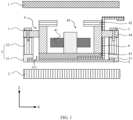
- the electronic device includes a rear cover 1, a screen 2, a middle frame 3, and a heat dissipation assembly 4.
- the middle frame 3 is located between the rear cover 1 and the screen 2.
- the middle frame 3 includes a fastened bottom wall 31 and a fastened convex rib 32.
- the bottom wall 31 is provided with a through hole 311.
- the convex rib 32 is located on an outer side of the through hole 311.
- the convex rib 32 protrudes in a thickness direction Z of the electronic device and towards a direction away from the bottom wall 31.
- the heat dissipation assembly 4 is disposed on the convex rib 32. At least a part of the heat dissipation assembly 4 is located in the through hole 311.
- the middle frame 3 is mainly configured to install various electronic components of the electronic device.
- the heat dissipation assembly 4 is configured to assist heat dissipation of a heat generation electronic component.
- the bottom wall 31 of the middle frame 3 is provided with a through hole 311.
- a bottom of the heat dissipation assembly 4 is disposed inside the through hole 311, to form an embedded structure.
- the embedded structure can reduce an overall thickness of the electronic device. As shown in FIG.
- the bottom wall 31 and the convex rib 32 may be of an integral structure or a split structure. This is not limited in this embodiment.
- an area of the through hole 311 should not be excessively large, and should be slightly greater than an area of the heat dissipation assembly 4.
- the electronic device provided in this embodiment of this application further includes a reinforcement member 5.
- the reinforcement member 5 is fastened to an end that is of the bottom wall 31 and that is away from the convex rib 32.
- the reinforcement member 5 covers the through hole 311.
- the middle frame 3 provides support and protection for the screen 2.
- stress concentration is easily generated on the bottom wall 31 around the through hole 311.
- a decrease in a bearing area also causes a decrease in structural strength of the middle frame 3, affecting reliability of the screen 2. Therefore, the reinforcement member 5 needs to be disposed to perform hole reinforcement on the middle frame 3.
- the reinforcement member 5 is fastened to the bottom wall 31, and can cover the whole through hole 311. In this way, a local reinforcement function is implemented, and structural strength of the bottom wall 31 around the through hole 311 is improved. Therefore, overall structural strength of the middle frame 3 is improved, ensuring reliability of the screen 2.
- the reinforcement member 5 may be fastened to the bottom wall 31 in a bonding manner. Specifically, as shown in FIG. 1 , a mounting groove may be provided on the bottom wall 31, glue 51 is applied in the mounting groove, and then the reinforcement member 5 is placed in the mounting groove to complete bonding.
- the heat dissipation assembly 4 includes a housing and a fan 41.
- the housing includes an upper cover 42, a lower cover 43, and a side panel 44.
- the upper cover 42, the lower cover 43, and the side panel 44 jointly enclose an accommodation space 45.
- the fan 41 is disposed in the accommodation space 45.
- the upper cover 42 is provided with an air inlet hole 421.
- the side panel 44 is provided with an air outlet hole 441.
- the air inlet hole 421 and the air outlet hole 441 separately communicate with the accommodation space 45.
- the heat dissipation assembly 4 uses an air cooling manner.
- Low-temperature cold air enters the accommodation space 45 from the air inlet hole 421 and in contact with the fan 41.
- a fan blade of the fan 41 rotates to accelerate air flow and form an airflow.
- the airflow can flow from the air outlet hole 441 to a heat generation electronic component, and exchange heat with the electronic component, to assist the electronic component in heat dissipation.
- the side panel 44 is not disposed around the fan 41, but uses a structure of surrounding the fan 41 in three sides. This can increase an area of the air outlet hole 441, and ensure that air volume flowing from the accommodation space 45 to the heat generation electronic component is large enough, improving heat dissipation effect of the heat dissipation assembly 4.
- a quantity of fans 41 is not limited in this embodiment.
- a dual-fan structure may be used, to improve heat dissipation performance of the electronic device.
- FIG. 2 there is an air inlet channel 10 between the upper cover 42 and the rear cover 1.
- the air inlet channel 10 communicates with the air inlet hole 421.
- the external low-temperature cold air may flow from the air inlet channel 10 to the air inlet hole 421.
- this embodiment ensures integrity and structural strength of the rear cover 1 are not damaged.
- At least a part of the convex rib 32 is disposed around the through hole 311.
- the side panel 44 is fastened to the convex rib 32.
- the convex rib 32 is disposed around the through hole 311, to form a structure in which the convex rib 32 surrounds the through hole 311 in three sides. In this way, structural strength of the bottom wall 31 around the through hole 311 is enhanced, and a location of the air outlet hole 441 is avoided, ensuring smooth air outlet of the heat dissipation assembly 4.
- At least a part of the side panel 44 can extend towards a direction close to the convex rib 32, and is stacked on an end portion of the convex rib 32. It is convenient for the convex rib to be fastened to the side panel 44. Specifically, as shown in FIG. 1 and FIG. 3 , in a width direction X of the heat dissipation assembly 4, both two sides of the side panel 44 are fastened to the convex rib 32 by using a fastener 7, improving installation stability of the heat dissipation assembly 4.
- the other part of the convex rib 32 can extend in a length direction Y of the heat dissipation assembly 4, to improve structural strength at another location of the bottom wall 31, and further improve overall strength of the middle frame 3.
- the upper cover 42 includes an upper cover diversion portion 422, and the lower cover 43 includes a lower cover diversion portion 431.
- the upper cover diversion portion 422 and the lower cover diversion portion 431 are disposed opposite to each other in the thickness direction Z of the electronic device.
- the upper cover diversion portion 422 and the lower cover diversion portion 431 are disposed opposite to each other in the thickness direction Z of the electronic device, so that a diversion channel can be formed.
- the diversion channel communicates with the air outlet hole 441, and is configured to guide an airflow flowing from the air outlet hole 441 to the heat generation electronic component, ensuring smooth air outlet of the heat dissipation assembly 4.
- the lower cover 43 further includes a lower cover body 432.
- the lower cover diversion portion 431 is connected to the lower cover body 432, and is inclined relative to the lower cover body 432 towards a direction close to the upper cover 42; and/or the upper cover 42 further includes an upper cover body 423, and the upper cover diversion portion 422 is connected to the upper cover body 423, and is inclined relative to the upper cover body 423 towards a direction away from the lower cover 43.
- the lower cover body 432 and the upper cover body 423 are configured to enclose the accommodation space 45 together with the side panel 44; the lower cover diversion portion 431 approaches the air outlet hole 441, and is configured to guide the airflow at the air outlet hole 441; and specifically, the lower cover diversion portion 431 is inclined relative to the lower cover body 432 towards a direction close to the upper cover 42, and a slope structure is formed, so that the airflow climbs upward along the slope and then flows to the heat generation electronic component, to ensure smooth flow-out of the airflow in the accommodation space 45, and avoid unsmooth air outlet of the heat dissipation assembly 4 due to block of the bottom wall 31; and/or the upper cover diversion portion 422 approaches a location of the air outlet hole 441, and is configured to cooperate with the lower cover diversion portion 431 for guiding; and specifically, the upper cover diversion portion 422 is inclined relative to the upper cover body 423 towards a direction away from the lower cover 43, and a slope structure is also formed, so that the upper cover diversion portion 4
- the included angle ⁇ between the lower cover diversion portion 431 and the lower cover body 432.
- the included angle ⁇ meets 120° ⁇ ⁇ ⁇ 170°.
- the included angle ⁇ may be specifically 120°, 130°, 150°, 165°, or 170°, or may be another value within the foregoing range. This is not limited herein.
- the included angle ⁇ is excessively small (for example, is less than 120°), an air outlet area of the heat dissipation assembly 4 is not large enough, and an air outlet volume is excessively small, affecting heat dissipation effect of the heat dissipation assembly 4.
- the included angle ⁇ is excessively large (for example, is greater than 170°)
- the lower cover diversion portion 431 approaches being horizontal.
- a diversion function is excessively small, and it cannot be ensured that the airflow can climb to a height above the bottom wall 31 and flow to the heat generation electronic component. This also affects heat dissipation effect of the heat dissipation assembly 4. Therefore, when the included angle ⁇ between the lower cover diversion portion 431 and the lower cover body 432 is 120° to 170°, it can be ensured that air outlet of the heat dissipation assembly 4 is smooth and that the air volume is large enough.
- the upper cover 42 further includes an upper cover reinforcement portion 424. At least a part of the upper cover body 423 is connected to the upper cover reinforcement portion 424. The upper cover reinforcement portion 424 protrudes towards a direction away from the lower cover 43 relative to the upper cover body 423.
- the upper cover reinforcement portion 424 protrudes towards the direction away from the lower cover 43 relative to the upper cover body 423. In this way, a local reinforcement function is implemented, structural strength of the upper cover body 423 connected to the upper cover reinforcement portion 424 is improved. Therefore, strength of the heat dissipation assembly 4 is further improved, improving a pressing resistance capability of the heat dissipation assembly 4.
- the upper cover reinforcement portion 424 and the upper cover body 423 may be of an integral structure, or may be of a split structure. This is not limited in this embodiment.
- a thickness of the upper cover reinforcement portion 424 may be 0.4 mm to 0.8 mm, to ensure that structural strength of the upper cover body 423 is effectively improved. Specifically, the thickness may be 0.4 mm, 0.5 mm, 0.6 mm, or 0.8 mm, or may be another value within the foregoing range. This is not limited herein.
- connection portions 423a are disposed on the upper cover body 423.
- the connection portions 423a are connected to the upper cover reinforcement portion 424.
- the connection portions 423a are disposed at two ends of the upper cover body 423.
- the two connection portions 423a are separately fastened to the convex rib 32.
- connection portions 423a are separately fastened to the convex rib 32 in the width direction X of the heat dissipation assembly 4. This can further improve installation stability of the heat dissipation assembly 4.
- the connection portions 423a are connected to the upper cover reinforcement portion 424.
- the connection portions 423a are connected to the convex rib 32 located on two sides of the heat dissipation assembly 4 to form an annular reinforcement structure as a whole. This can further implement a reinforcement function, and improve structural strength of the middle frame 3.
- force applied to the convex rib 32 can be more evenly distributed, improving structural stability of the convex rib 32.
- connection portion 423a may be fastened to the convex rib 32 by using the fastener 7.
- the fastener 7 may be specifically a screw or another connecting member. This is not limited in this embodiment.
- the electronic device further includes a flexible circuit board 6.
- One end that is of the lower cover 43 and that is away from the fan 41 is provided with a groove. At least a part of the flexible circuit board 6 is disposed in the groove.
- One end of the flexible circuit board 6 is connected to the heat dissipation assembly 4, and the other end is connected to the mainboard of the electronic device.
- one end that is of the lower cover 43 and that is away from the fan 41 may be provided with the groove (for example, manufactured through an etching process), and then the flexible circuit board 6 is disposed in the groove, that is, the flexible circuit board 6 is embedded in the bottom wall of the lower cover 43.
- this solution can further reduce a thickness of the electronic device, and helps to implement lightness and thinness of the electronic device.
- a thickness of the electronic device can be reduced without affecting heat dissipation effect of the heat dissipation assembly 4, and structural strength of the middle frame 3 is improved by disposing the reinforcement member 5 and the upper cover reinforcement portion 424. Therefore, reliability of the heat dissipation assembly 4 and the screen 2 is improved, and that the fan 41 and the screen 2 do not fail when the electronic device is used is ensured.
Landscapes
- Engineering & Computer Science (AREA)
- Microelectronics & Electronic Packaging (AREA)
- Physics & Mathematics (AREA)
- Thermal Sciences (AREA)
- Theoretical Computer Science (AREA)
- Signal Processing (AREA)
- Human Computer Interaction (AREA)
- General Engineering & Computer Science (AREA)
- General Physics & Mathematics (AREA)
- Cooling Or The Like Of Electrical Apparatus (AREA)
Applications Claiming Priority (2)
| Application Number | Priority Date | Filing Date | Title |
|---|---|---|---|
| CN202223387665.1U CN219329940U (zh) | 2022-12-16 | 2022-12-16 | 一种电子设备 |
| PCT/CN2023/135873 WO2024125324A1 (zh) | 2022-12-16 | 2023-12-01 | 一种电子设备 |
Publications (2)
| Publication Number | Publication Date |
|---|---|
| EP4451817A1 true EP4451817A1 (de) | 2024-10-23 |
| EP4451817A4 EP4451817A4 (de) | 2025-06-11 |
Family
ID=87064875
Family Applications (1)
| Application Number | Title | Priority Date | Filing Date |
|---|---|---|---|
| EP23902521.6A Pending EP4451817A4 (de) | 2022-12-16 | 2023-12-01 | Elektronische vorrichtung |
Country Status (4)
| Country | Link |
|---|---|
| US (1) | US20250176149A1 (de) |
| EP (1) | EP4451817A4 (de) |
| CN (1) | CN219329940U (de) |
| WO (1) | WO2024125324A1 (de) |
Families Citing this family (2)
| Publication number | Priority date | Publication date | Assignee | Title |
|---|---|---|---|---|
| CN219329940U (zh) * | 2022-12-16 | 2023-07-11 | 华为技术有限公司 | 一种电子设备 |
| CN120856818A (zh) * | 2024-04-30 | 2025-10-28 | 华为技术有限公司 | 电子设备 |
Family Cites Families (6)
| Publication number | Priority date | Publication date | Assignee | Title |
|---|---|---|---|---|
| JP4309189B2 (ja) * | 2003-06-30 | 2009-08-05 | パナソニック株式会社 | 可搬型電子機器 |
| WO2015008413A1 (ja) * | 2013-07-17 | 2015-01-22 | パナソニック株式会社 | 有機el表示装置 |
| CN110740611A (zh) * | 2018-07-20 | 2020-01-31 | 深圳富泰宏精密工业有限公司 | 散热器及具有该散热器的电子装置 |
| CN110740619B (zh) * | 2019-10-15 | 2020-12-29 | Oppo(重庆)智能科技有限公司 | 一种电子设备 |
| CN212164015U (zh) * | 2020-03-24 | 2020-12-15 | 华为技术有限公司 | 移动终端、中框组件及散热组件 |
| CN219329940U (zh) * | 2022-12-16 | 2023-07-11 | 华为技术有限公司 | 一种电子设备 |
-
2022
- 2022-12-16 CN CN202223387665.1U patent/CN219329940U/zh active Active
-
2023
- 2023-12-01 WO PCT/CN2023/135873 patent/WO2024125324A1/zh not_active Ceased
- 2023-12-01 US US18/842,496 patent/US20250176149A1/en active Pending
- 2023-12-01 EP EP23902521.6A patent/EP4451817A4/de active Pending
Also Published As
| Publication number | Publication date |
|---|---|
| US20250176149A1 (en) | 2025-05-29 |
| WO2024125324A1 (zh) | 2024-06-20 |
| CN219329940U (zh) | 2023-07-11 |
| EP4451817A4 (de) | 2025-06-11 |
Similar Documents
| Publication | Publication Date | Title |
|---|---|---|
| EP4451817A1 (de) | Elektronische vorrichtung | |
| US6611425B2 (en) | Electronic apparatus | |
| US8727717B2 (en) | Serial fan module and frame structure thereof | |
| US11262819B2 (en) | Electronic device | |
| US9125300B2 (en) | Electronic device with heat sink structure | |
| US12250793B2 (en) | Mobile terminal | |
| US10927848B2 (en) | Fan module and electronic device | |
| US7929302B2 (en) | Cooling device | |
| US20070097643A1 (en) | Thermal structure for electric devices | |
| US8014149B2 (en) | Fan module for electronic device | |
| CN115562450B (zh) | 终端 | |
| US20250374433A1 (en) | Space-saving backplate assembly for a compression attached memory module | |
| US12490404B2 (en) | Centrifugal fan module | |
| CN105373191A (zh) | 具有散热结构的笔记本电脑 | |
| CN213343145U (zh) | 电子设备 | |
| CN1093652C (zh) | 信息处理单元的机械结构 | |
| CN219574748U (zh) | 一种散热结构及电子设备 | |
| WO2022257869A1 (zh) | 一种卡托组件和电子设备 | |
| US20240264646A1 (en) | Electronic Device | |
| CN223078864U (zh) | 数据储存装置及电子设备 | |
| CN218971493U (zh) | 一种蜗舌结构、离心风扇及电子设备 | |
| CN221708018U (zh) | 一种取代泡绵结构的笔记本散热结构 | |
| CN112188814B (zh) | 电子设备 | |
| CN117850553B (zh) | 一种笔记本电脑及其散热结构 | |
| CN223482937U (zh) | 散热风扇与电子设备 |
Legal Events
| Date | Code | Title | Description |
|---|---|---|---|
| STAA | Information on the status of an ep patent application or granted ep patent |
Free format text: STATUS: THE INTERNATIONAL PUBLICATION HAS BEEN MADE |
|
| PUAI | Public reference made under article 153(3) epc to a published international application that has entered the european phase |
Free format text: ORIGINAL CODE: 0009012 |
|
| STAA | Information on the status of an ep patent application or granted ep patent |
Free format text: STATUS: THE APPLICATION HAS BEEN PUBLISHED |
|
| AK | Designated contracting states |
Kind code of ref document: A1 Designated state(s): AL AT BE BG CH CY CZ DE DK EE ES FI FR GB GR HR HU IE IS IT LI LT LU LV MC ME MK MT NL NO PL PT RO RS SE SI SK SM TR |
|
| STAA | Information on the status of an ep patent application or granted ep patent |
Free format text: STATUS: REQUEST FOR EXAMINATION WAS MADE |
|
| 17P | Request for examination filed |
Effective date: 20241220 |
|
| A4 | Supplementary search report drawn up and despatched |
Effective date: 20250514 |
|
| RIC1 | Information provided on ipc code assigned before grant |
Ipc: G02F 1/1333 20060101ALI20250508BHEP Ipc: H04M 1/02 20060101ALI20250508BHEP Ipc: G06F 1/20 20060101ALI20250508BHEP Ipc: H05K 7/20 20060101AFI20250508BHEP |
|
| DAV | Request for validation of the european patent (deleted) | ||
| DAX | Request for extension of the european patent (deleted) |