EP4451555A2 - System und verfahren zur bestimmung der eigenschaften einer fotovoltaischen tafel - Google Patents
System und verfahren zur bestimmung der eigenschaften einer fotovoltaischen tafel Download PDFInfo
- Publication number
- EP4451555A2 EP4451555A2 EP24170882.5A EP24170882A EP4451555A2 EP 4451555 A2 EP4451555 A2 EP 4451555A2 EP 24170882 A EP24170882 A EP 24170882A EP 4451555 A2 EP4451555 A2 EP 4451555A2
- Authority
- EP
- European Patent Office
- Prior art keywords
- power
- photovoltaic panel
- terminals
- terminal
- power device
- Prior art date
- Legal status (The legal status is an assumption and is not a legal conclusion. Google has not performed a legal analysis and makes no representation as to the accuracy of the status listed.)
- Pending
Links
Images











Classifications
-
- H—ELECTRICITY
- H02—GENERATION; CONVERSION OR DISTRIBUTION OF ELECTRIC POWER
- H02S—GENERATION OF ELECTRIC POWER BY CONVERSION OF INFRARED RADIATION, VISIBLE LIGHT OR ULTRAVIOLET LIGHT, e.g. USING PHOTOVOLTAIC [PV] MODULES
- H02S40/00—Components or accessories in combination with PV modules, not provided for in groups H02S10/00 - H02S30/00
- H02S40/30—Electrical components
- H02S40/34—Electrical components comprising specially adapted electrical connection means to be structurally associated with the PV module, e.g. junction boxes
-
- H—ELECTRICITY
- H02—GENERATION; CONVERSION OR DISTRIBUTION OF ELECTRIC POWER
- H02J—ELECTRIC POWER NETWORKS; CIRCUIT ARRANGEMENTS OR SYSTEMS FOR SUPPLYING OR DISTRIBUTING ELECTRIC POWER; SYSTEMS FOR STORING ELECTRIC ENERGY
- H02J7/00—Circuit arrangements for charging or discharging batteries or for supplying loads from batteries
- H02J7/34—Parallel operation in networks using both storage and other DC sources, e.g. providing buffering
- H02J7/35—Parallel operation in networks using both storage and other DC sources, e.g. providing buffering with light sensitive cells
-
- H—ELECTRICITY
- H02—GENERATION; CONVERSION OR DISTRIBUTION OF ELECTRIC POWER
- H02S—GENERATION OF ELECTRIC POWER BY CONVERSION OF INFRARED RADIATION, VISIBLE LIGHT OR ULTRAVIOLET LIGHT, e.g. USING PHOTOVOLTAIC [PV] MODULES
- H02S40/00—Components or accessories in combination with PV modules, not provided for in groups H02S10/00 - H02S30/00
- H02S40/30—Electrical components
- H02S40/32—Electrical components comprising DC/AC inverter means associated with the PV module itself, e.g. AC modules
-
- H—ELECTRICITY
- H02—GENERATION; CONVERSION OR DISTRIBUTION OF ELECTRIC POWER
- H02S—GENERATION OF ELECTRIC POWER BY CONVERSION OF INFRARED RADIATION, VISIBLE LIGHT OR ULTRAVIOLET LIGHT, e.g. USING PHOTOVOLTAIC [PV] MODULES
- H02S40/00—Components or accessories in combination with PV modules, not provided for in groups H02S10/00 - H02S30/00
- H02S40/30—Electrical components
- H02S40/36—Electrical components characterised by special electrical interconnection means between two or more PV modules, e.g. electrical module-to-module connection
-
- H—ELECTRICITY
- H02—GENERATION; CONVERSION OR DISTRIBUTION OF ELECTRIC POWER
- H02S—GENERATION OF ELECTRIC POWER BY CONVERSION OF INFRARED RADIATION, VISIBLE LIGHT OR ULTRAVIOLET LIGHT, e.g. USING PHOTOVOLTAIC [PV] MODULES
- H02S50/00—Monitoring or testing of PV systems, e.g. load balancing or fault identification
- H02S50/10—Testing of PV devices, e.g. of PV modules or single PV cells
-
- H—ELECTRICITY
- H02—GENERATION; CONVERSION OR DISTRIBUTION OF ELECTRIC POWER
- H02S—GENERATION OF ELECTRIC POWER BY CONVERSION OF INFRARED RADIATION, VISIBLE LIGHT OR ULTRAVIOLET LIGHT, e.g. USING PHOTOVOLTAIC [PV] MODULES
- H02S50/00—Monitoring or testing of PV systems, e.g. load balancing or fault identification
- H02S50/10—Testing of PV devices, e.g. of PV modules or single PV cells
- H02S50/15—Testing of PV devices, e.g. of PV modules or single PV cells using optical means, e.g. using electroluminescence
-
- Y—GENERAL TAGGING OF NEW TECHNOLOGICAL DEVELOPMENTS; GENERAL TAGGING OF CROSS-SECTIONAL TECHNOLOGIES SPANNING OVER SEVERAL SECTIONS OF THE IPC; TECHNICAL SUBJECTS COVERED BY FORMER USPC CROSS-REFERENCE ART COLLECTIONS [XRACs] AND DIGESTS
- Y02—TECHNOLOGIES OR APPLICATIONS FOR MITIGATION OR ADAPTATION AGAINST CLIMATE CHANGE
- Y02E—REDUCTION OF GREENHOUSE GAS [GHG] EMISSIONS, RELATED TO ENERGY GENERATION, TRANSMISSION OR DISTRIBUTION
- Y02E10/00—Energy generation through renewable energy sources
- Y02E10/50—Photovoltaic [PV] energy
- Y02E10/56—Power conversion systems, e.g. maximum power point trackers
Definitions
- the disclosure relates generally to photovoltaic power systems. More specifically, the disclosure relates to a system and method for capturing an image to determine a characteristic of a photovoltaic module.
- Photovoltaic panels in real-world environments may be subjected to physical damage (e.g., cracks in photovoltaic cells, manufacturing defects, defects in the materials of the panels, disconnected conductors, hot spots, and the like). Such physical damage may affect the performance of the photovoltaic panel and may even be a safety concern (e.g., hot spots may lead to fire). It is beneficial to evaluate the physical state of the photovoltaic panels. However, when photovoltaic panels are wired into a power generation system, such evaluation can be difficult due to the panel's connection to other devices, such as power converters, system controllers, loads, etc.
- other devices such as power converters, system controllers, loads, etc.
- Performing I-V curve measurements when the photovoltaic panel does not produce power may be referred to as "dark I-V curve" measurements.
- Performing electroluminescence imaging and/or dark I-V curve measurements may include providing a reverse current to the photovoltaic panel.
- providing reverse current to the photovoltaic panel during a low irradiance condition, for electroluminescence imaging purposes, and/or dark I-V curve measurements may utilize a power device, where the power device may comprise an auxiliary power circuit that provides power to the power device from either the photovoltaic panel or the power source.
- the disclosure provides a power device that may comprise a diode restricting current flowing from the power source toward a photovoltaic panel (e.g., thereby limiting an auxiliary power circuit of the power device from operating).
- the power device may comprise a controller, which may control a switch to a conducting state, wherein the switch is connected across the diode, thus providing a path for current to flow from the power source to the photovoltaic panel.
- the switch may be a part of a power converter, and the controller may control the power converter to provide reverse current to the photovoltaic panel.
- the disclosure further provides a system comprising a plurality of photovoltaic panels, where one or more of the photovoltaic panels may be coupled to a corresponding one or more power devices.
- the one or more power devices may be coupled to a power system controller.
- the power system controller may be coupled to a power source and to an imager.
- the power converter may comprise a diode, which may restrict a reverse current from flowing to the corresponding photovoltaic panel.
- the power device may also comprise an auxiliary power circuit, which may provide power to the power device from either the photovoltaic panel or the power source.
- the power device may comprise a controller that controls a switch to a conducting state, wherein the switch is connected across the diode, thus providing a path for current to flow from the power source to the photovoltaic panel.
- the method may comprise a power system controller determining to provide power, from a power source to a power device, for electroluminescence imaging of a photovoltaic panel.
- the photovoltaic panel may be connected to the power device.
- the power device may comprise a diode restricting current flow from the power source toward the photovoltaic panel.
- the method may comprise the power device detecting the receipt of auxiliary power from the power source and the receipt of an instruction to provide power to the photovoltaic panel.
- the method may comprise controlling the power device to provide power to the photovoltaic panel based on determining that the photovoltaic panel is not producing power.
- Controlling the power device to provide power to the photovoltaic panel may comprise controlling a switch to provide a current path from the power source to the photovoltaic panel.
- the method may also comprise controlling, by the power system controller, an imager to capture an image of the photovoltaic panel for electroluminescence analysis and analyzing, by a processor, the captured image to determine a physical state of the photovoltaic panel.
- a power system controller may produce a plurality of voltage levels to a string of serially connected power devices. Responsive to a voltage at its output terminals, a power device in the string may create a path for current to flow to a corresponding photovoltaic panel. The power system controller may increase the voltage level across the string, resulting in a reverse current flowing through the photovoltaic panel. Each power device may measure the voltage level across its output terminals and the reverse current through the corresponding photovoltaic panel. The power device or the power system controller may use these measurements for photovoltaic panel characterization.
- a power system controller may produce a voltage level to a string of serially connected power devices and transmit a plurality of power levels to each of the power devices in the string. Responsive to a voltage at its output terminals and based on the received power levels from the power system controller, a power device in the string may convert power to produce a voltage across, and a reverse current through, the corresponding photovoltaic panel. Each power device may measure the voltage level across, and the reverse current through, the corresponding photovoltaic panel. The power device or the power system controller may use these measurements for photovoltaic panel characterization.
- the method may comprise a power system controller determining to provide power from a power source to a power device for electroluminescence imaging of a photovoltaic panel.
- the photovoltaic panel may be connected to the power device.
- the method may comprise the power device determining the receipt of auxiliary power from the power source and the receipt of instruction to provide power to the photovoltaic panel.
- the method may comprise controlling the power device to provide a reverse current to the photovoltaic panel. Controlling the power device to provide reverse current to the photovoltaic panel may comprise controlling a switch to provide a current path from the power source to the photovoltaic panel.
- the method may also comprise controlling, by the power system controller, an imager to capture an image of the photovoltaic panel for electroluminescence analysis and analyzing, by a processor, the captured image to determine a physical location of the photovoltaic panel.
- the method may also comprise determining an association between the photovoltaic panel and the corresponding power device.
- a characteristic of a photovoltaic panel where the photovoltaic panels are installed as part of a photovoltaic power system.
- the physical state of the photovoltaic panels may be evaluated "on-site" (e.g., at the location where the panels are installed).
- Determining a characteristic of a photovoltaic panel may comprise evaluating a physical state of a photovoltaic panel, for example, using electroluminescence imaging or dark I-V curve measurements.
- a reverse current e.g., a current in the opposite direction to current produced by the panel when illuminated
- Such a reverse current may cause the photovoltaic panel to emit radiation such as infrared radiation.
- An image e.g., an infrared image
- an analysis of the captured image may provide information relating to the physical state and the performance of the panel. For example, cracks, hot-stops, and other damage, deterioration, or defects may be visible in the captured image.
- the physical state of a photovoltaic panel may be based on determining a current versus voltage curve (referred to as "I-V curve") of the photovoltaic panel when the photovoltaic panel does not produce power (e.g., during low irradiance conditions such as during the night).
- an I-V curve of a photovoltaic panel may provide information relating to parameters of the photovoltaic panel such as the open circuit voltage (Voc), the short circuit current (Isc) the series resistance (Rs), the shunt resistance (Rsh), or fill factor (FF).
- Voc open circuit voltage
- Isc short circuit current
- Rs series resistance
- Rsh shunt resistance
- FF fill factor
- Determining a characteristic or characteristics of a photovoltaic panel may comprise determining a physical location (e.g., geo-location or relative location) of the photovoltaic panel in the site, using electroluminescence imaging.
- the photovoltaic panels may be coupled to corresponding power devices, which may control the power provided by the photovoltaic panel or panels.
- a power device coupled to a corresponding photovoltaic panel may provide a reverse current to the photovoltaic panel.
- the power device may comprise a power converter.
- Such power converters may comprise a diode, which may restrict a reverse current from flowing to the photovoltaic panel.
- the diode may be connected to, or be a part of, a switch (e.g., a body diode of a transistor switch). Examples of such power converters are shown in Figures 9A-9E .
- the power converters may include a diode 317 that restricts reverse current from flowing toward the corresponding photovoltaic panel (e.g., from downstream terminals 312 to upstream terminals 310). Diode 317 may be connected across a switch 316, which provides a path for the reverse current when controlled to a conducting state, for example, by the power device.
- the power used by the power device for the operation of the various modules of the power devices may be received from the corresponding photovoltaic panel.
- auxiliary power may be received from the corresponding photovoltaic panel.
- electroluminescence imaging and/or dark I-V curve measurements are performed when the photovoltaic panel is not producing power (e.g., during low irradiance conditions such as during the night).
- a power device which receives the auxiliary power thereof only from the corresponding photovoltaic panel may not be able to operate, and (in view of a diode restricting reverse current flow) may not be able to provide a path for a reverse current to flow to the photovoltaic panel for electroluminescence imaging purposes and/or dark I-V curve measurements (e.g., the power device would not be able to control the switch to transition to a conducting state).
- aspects of the disclosure herein may provide a system comprising a plurality of photovoltaic panels, where one or more of the photovoltaic panels may be coupled to a corresponding one or more power devices.
- the one or more power devices may be coupled to a power system controller.
- the power system controller may be coupled to a power source and to an imager. Examples of such power systems are shown in Figures 1A-1D .
- the one or more power devices may comprise a power converter.
- the power converter may comprise a diode which may restrict a reverse current from flowing to the corresponding photovoltaic panel (e.g., as shown in Figures 9A-9E ).
- a power device may comprise an auxiliary power circuit, which may receive power either from the photovoltaic panel, from the power source (e.g., via power system controller), or from both. Examples of such power devices is shown in Figures 3A-3E , where auxiliary power circuit 308 may receive power from a photovoltaic panel (e.g., via first and second terminals 310-1 and 310-2), from a power source (e.g., via third and fourth terminals 312-1 and 312-2), or from both.
- auxiliary power circuit 308 may receive power from a photovoltaic panel (e.g., via first and second terminals 310-1 and 310-2), from a power source (e.g., via third and fourth terminals 312-1 and 312-2), or from both.
- a power device controller may control the switch connected to the diode (e.g., switch 316 - Figures 3A , 9A-9E , 11A , 12B )) to transition to a conducting state, thus providing a path for a reverse current to flow to the corresponding photovoltaic panel.
- Receiving auxiliary power from a power source may have additional advantages. Such advantages may be updating a software of the power device during low irradiation conditions, detecting the presences of the corresponding photovoltaic panel (e.g., theft detection), communicating with the power system controller to name a few.
- a power device may receive power from a power source (e.g., via a power system controller), and employ that power for two purposes.
- the first purpose may be using the power from the power source as auxiliary power for the operation of the power device, and controlling the switch connected to the diode to transition to a conducting state.
- the second purpose may be using the power from the power source to provide reverse current to the photovoltaic panel for electroluminescence imaging and/or dark I-V curve measurements purposes.
- the power may be used for either or both purposes.
- a system according to the disclosure herein may provide on-site capabilities of evaluating the physical state of the photovoltaic panels (e.g., by detecting cracks, manufacturing defects, disconnected conductors, hot spots, estimating the series or shunt resistances and the like), thus increasing the reliability and safety of the system.
- the power device may comprise a bypass circuit which may bypass the power converter, and may provide a path for a reverse current to flow to the corresponding photovoltaic panel or panels.
- a power device according to aspects of the disclosure herein may enable a reverse current flow for on-site electroluminescence imaging.
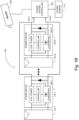
- System 100 may be used for electroluminescence imaging of a photovoltaic panel or panels.
- system 100 may enable electroluminescence imaging of a photovoltaic panel or panels on-site.
- System 100 may comprise a photovoltaic array 113 (shown in Figure 2 ), which may comprise one or more strings such as string 112.
- String 112 may comprise one or more photovoltaic panels 114-1, 114-2, ..., 114-N, and a one or more power devices 116-1, 116-2, ..., 116-N connected in series. Examples of power device 116-N are further elaborated below in conjunction with Figures 3A-3E .
- Figure 1C shows that photovoltaic panels 114-1, 114-2, ..., 114-N may be connected in series.
- the serially connected photovoltaic panels 114-1, 114-2, ..., 114-N may be connected to a power device 116-1.
- Figure 1D shows various examples for mounting imager 108, such as on an aerial vehicle 132 (e.g., a drone, a helicopter, an airplane).
- Imager 108 may be mounted on a robot 134 traversing string 112 (e.g., on wheels, or rails).
- Imager 108 may be mounted on a pole 136 (e.g., a telescopic pole) above string 112.
- Imager 108 may be mounted on satellite 138.
- imager 108 may be connected to power system controller 104 with wires or wirelessly, and the power system controller may send instructions to imager 108 or receive images from imager 108 via communications interface 206.
- photovoltaic panels 114-1, 114-2, ..., 114-N may produce power.
- Each of power devices 116-1, 116-2, ..., 116-N may receive auxiliary power from a corresponding one of photovoltaic panels 114-1, 114-2, ..., 114-N, and convert power from the corresponding one of photovoltaic panels 114-1, 114-2, ..., 114-N.
- Power system controller 104 may provide the power from power devices 116-1, 116-2, ..., 116-N to a load (e.g., a house, a factory, a power storage device/system, a power distribution network).
- a load e.g., a house, a factory, a power storage device/system, a power distribution network.
- power system controller 104 may provide power at terminals 118-1 and 118-2 (e.g., from power source 110). For example, providing power may relate to generating a voltage between terminals 118-1 and 118-2 such that a current may be drawn from the power system controller 104 by one or more of power devices 116-1-116-N.
- Each of power devices 116-1, 116-2, ..., 116-N may receive auxiliary power from the power source at terminals 118-1 and 118-2.
- Example structure and operation of a power device such as the power devices 116-1, 116-2, ..., 116-N is further elaborated below in conjunction with Figures 3A-3E .
- Each of power devices 116-1, 116-2, ..., 116-N may employ power from terminals 118-1 and 118-2, and provide a current, which may be referred to as reverse current, to the corresponding one of the photovoltaic panels 114-1, 114-2, ..., 114-N.
- photovoltaic panel 114 In a case where reverse current flows through photovoltaic panel 114, light or radiation (e.g., in the infrared spectrum) may be emitted by photovoltaic panel 114.
- Imager 108 may capture an image of the light or radiation emitted from photovoltaic panels 114-1, 114-2, ..., 114-N for electroluminescence analysis.
- the power system controller 104 may comprise an inverter.
- Power system controller 104 may comprise a central controller 202, a power converter 204, a communications interface 206, and sensor(s) 208.
- Central controller 202 may be connected to power converter 204, to communications interface 206, to sensor(s) 208, and to imager 108.
- Power converter 204 may be connected to photovoltaic array 113 and to power source 110. It is noted that in a case where the one or more power devices 116-1, 116-2, ..., 116-N produce AC power (e.g., in the instance of microinverters), power converter 204 may be replaced with a power combiner.
- Central controller 202 may be partially or fully implemented as one or more computing devices or may include one or more processors, such as an Application Specific Integrated Circuit (ASIC) controller, Field Programmable Gate Array (FPGA) controller, a microcontroller, or a multipurpose computer.
- Central controller 202 may comprise one or more processors 210, connected to memory 212 and Input/Output (I/O) ports 214.
- Central controller 202 may comprise a user interface 216 (e.g., a keyboard, a mouse, a display, a microphone, a speaker, a touch screen, or a touchpad).
- Memory 212 may store computer readable instructions as well as data (e.g., measurements from sensor(s) 208 or parameters).
- I/O ports 214 may be configured to connect modules (e.g., sensor(s) 208, communication interface 206, power converter 204, imager 108, server 115, or other modules of system 100) to processor 210.
- the one or more processors 210 may execute the instructions, which may result in the processor 210 performing one or more steps or functions as described herein that are attributed to one or both of central controller 202 and processor 210.
- Communications interface 206 may be a receiver, a transmitter, or a transceiver, and may be configured to communicate, based on a communications protocol, signals with one or more other transmitters, receivers, or transceivers, over a medium.
- the communication protocol may define one or more characteristics of the signals and/or of communications using signals, such as a transmission frequency or frequencies, a modulation scheme (e.g., Amplitude shift keying - ASK, Frequency shift keying - FSK, Quadrature Phase Shift Keying - QPSK, Quadrature Amplitude Modulation - QAM, ON OFF keying - OOK), multiple access scheme (e.g., Time Division Multiple Access - TDMA, Frequency Division Multiple Access - FDMA, Code Division Multiple Access - CDMA, Carrier Sense Multiple Access - CSMA, Aloha), encoding/decoding schemes (e.g., Non Return to Zero - NRZ, Manchester coding, Block coding), or any other characteristic.
- the medium may be a wired or a wireless medium.
- a wired medium may be a dedicated communications cable (e.g., twisted pair, coaxial cable).
- a wired medium may include power lines connecting the power devices 116-1, 116-2, ..., 116-N to the power converter 204.
- Sensor(s) 208 may comprise one or more voltage sensors (e.g., implemented by employing a resistive or capacitive divider, a resistive or capacitive bridge, or comparators), one or more current sensors (e.g., implemented by employing a Current Transformer (CT) sensor, a Hall Effect sensor, or a zero flux sensor), or one or more frequency sensors.
- voltage sensors e.g., implemented by employing a resistive or capacitive divider, a resistive or capacitive bridge, or comparators
- current sensors e.g., implemented by employing a Current Transformer (CT) sensor, a Hall Effect sensor, or a zero flux sensor
- CT Current Transformer
- power device 116 may receive auxiliary power either from a corresponding photovoltaic panel, from a power source, or from both.
- power device 116 may comprise a power converter 300, a first terminal 310-1 a second terminal 310-2, a third terminal 312-1, and a fourth terminal 312-2.
- Power device 116 may comprise a power device controller 302, a power device communications interface 304, sensor(s) 306, and/or an auxiliary power circuit 308.
- Power device may comprise gate drivers 309.
- Power converter 300 may include a bi-directional DC-DC converter or a bi-directional DC-AC converter (e.g., an inverter, which may also operate as a rectifier), and may comprise a power converter that includes a plurality of switches, as may further be elaborated below in conjunction with Figures 9A-9E .
- Power converter 300 may comprise a switch 316, which may comprise a diode 317 (e.g., a body diode of switch 316, or a discrete diode connected across switch 316).
- the cathode of diode 317 may be coupled to the third terminal 312-1, and the anode of diode 317 may be coupled to first terminal 310-1.
- the cathode of diode 317 may be coupled to second terminal 310-2, and the anode of diode 317 may be coupled to fourth terminal 312-2.
- diode 317 may restrict current from flowing from third terminal 312-1 toward first terminal 310-1, or from second terminal 310-2 toward fourth terminal 312-2.
- first terminal 310-1 and second terminal 310-2 may be abbreviated as terminals 310 or upstream terminals 310 or upstream interface 310.
- Third terminals 312-1 and fourth terminal 312-2 may be abbreviated as terminals 312 or downstream terminals 312 or downstream interface 312.
- Power device communications interface 304 may configured to communicate with communications interface 206.
- Sensors 306 may be an example of sensors 208 ( Figure 2 ).
- Power device controller 302 may control power converter 300, optionally, via gate drivers 309.
- Power device controller 302 may be connected to power device communications interface 304 and to sensor(s) 306.
- Auxiliary power circuit 308 may be connected to first and second terminals 310-1 and 310-2, to third and fourth terminals 312-1 and 312-2, to power device controller 302, and to power device communications interface 304.
- auxiliary power circuit 308 may be configured to provide power to power device controller 302, to power device communications interface 304, or to both, from either first terminal 310-1 and second terminal 310-2, or from third terminal 312-1 and fourth terminal 312-2.
- Power device controller 302 may control power converter 300, optionally via gate drivers 309, to convert power from the first and second terminals 310-1 and 310-2 to third and fourth terminals 312-1 and 312-2. Power device controller 302 may control power converter 300 to convert power from the third and fourth terminal 312-1 and 312-2, to the first and second terminals 310-1 and 310-2.
- first and second terminals 310-1 and 310-2 may be connected to a photovoltaic panel, such as photovoltaic panel 114.
- Third and fourth terminals 312-1 and 312-2 may be connected to other power devices 116 (e.g., in a series string or in parallel) or to terminals 118-1 and 118-2 of the power system controller 104.
- photovoltaic panel 114 may generate power.
- Auxiliary power circuit 308 may provide power for the operation of power device 116 from photovoltaic panel 114.
- Power device controller 302 may control power converter 300 to draw power from the photovoltaic panel 114, and provide (e.g., either directly or via string 112) power to power system controller 104.
- Power device controller 302 may control power converter 300 to draw power from photovoltaic panel 114 at an MPP of photovoltaic panel 114.
- the power device controller 302 may use an MPP Tracking (MPPT) algorithm (e.g., using perturb and observe, incremental conductance, or ripple correlation).
- MPPT MPP Tracking
- auxiliary power circuit 308 may provide power for the operation of power device 116 from another power source (e.g., via third and fourth terminals 312-1 and 312-2 from power source 110).
- Power device controller 302 may control power converter 300 to provide power (e.g., from power source 110 via power converter 204) to photovoltaic panel 114, to provide reverse current to photovoltaic panel 114, for example, for electroluminescence imaging or dark I-V curve measurements.
- Low irradiance conditions may be naturally occurring (e.g., during the night) or artificially occurring, by covering photovoltaic panel 114 (e.g., imager 108 may be located under the cover as well).
- power device 116 may be configured to draw power produced by photovoltaic panel 114, or provide power to photovoltaic panel 114 (e.g., from power source 110). In both instances, power device controller 302 and/or power device communications interface 304 may need power to operate (e.g., may also be referred to as auxiliary power). In instances where a power converter includes a diode such as diode 317, and the auxiliary power circuit of the power converter is not connected to the downstream terminals of the power converter, or in instances where the corresponding photovoltaic panel does not produce power, the auxiliary power circuit may not provide power to power device.
- auxiliary power circuit 308 may be connected to first terminal 310-1 and second terminal 310-2, and to third terminal 312-1 and fourth terminal 312-2.
- power converter 300 may receive auxiliary power either from the corresponding photovoltaic panel 114 (e.g., coupled to first terminal 310-1 and second terminal 310-2), from power source 110 (e.g., coupled to first terminal 310-1 and second terminal 310-2 via power system controller 104), or from both.
- auxiliary power circuit 308 may control switch 316 to a conducting state, thus allowing current (e.g., reverse current) to flow to photovoltaic panel 114.
- auxiliary power circuit 308 may provide auxiliary power to the components within power device 116. In instances where both photovoltaic panel 114 and power system controller 104 provide power, auxiliary power circuit 308 may provide auxiliary power to the components within power device 116 from photovoltaic panel 114 and from power source 110.
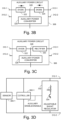
- FIGS 3B and 3C show examples of auxiliary power circuit 308.
- Auxiliary power circuit 308 may comprise a first diode 322 and a second diode 324 as shown in Figure 3B .
- Auxiliary power circuit 308 may optionally comprise an auxiliary power converter 328.
- the cathodes of diodes 322 and 324 may be connected at a connection point 326.
- the anode of first diode 322 may be connected to first terminal 310-1.
- the anode of second diode 324 may be connected to third terminal 312-1.
- Connection point 326 may be connected to the components and modules of power device 116.
- connection point 326 may be connected to the input of auxiliary power converter 328.
- auxiliary power converter 328 may be connected to the components and modules of power device 116.
- Auxiliary power converter 328 may be a DC-DC converter (e.g., a buck converter, a boost converter, a buck and boost converter, or a buck-boost converter).
- Auxiliary power converter 328 may be controlled by a PWM controller which may receive its operating power either from first and second terminals 310-1 and 310-2, or from third and fourth terminals 312-1 and 312-2.
- a PWM controller may be integrated into auxiliary power converter 328 or power device controller 302 or may be a separate controller.
- First diode 322 or second diode 324 may be implemented by ideal diode circuits (e.g., using ideal diode integrated circuits such as LTC4451 or LM73100, or using discrete components).
- First diode 322 and second diode 324 may be OR-ing diodes (e.g., diodes which perform a logical OR operation) configured to provide power device 116 with auxiliary power from one of photovoltaic panel 114 (e.g., via first and second terminals 310-1 and 310-2) or from power system controller 104 (e.g., via third and fourth terminals 312-1 and 312-2).
- OR-ing diodes e.g., diodes which perform a logical OR operation
- second diode 324 may be replaced with a rectifier 330, as shown in Figure 3C .
- Rectifier 330 may transform the AC voltage to DC voltage.
- power system controller 104 may use power lines connecting power devices 116-1, 116-2, ..., 116-N to power converter 204 as a communications medium.
- power system controller 104 may use communications interface 206 to produce an alternating voltage signal (e.g., an AC voltage) between, and/or an AC current signal on, terminals 118-1 and 118-2, and thus on lines connecting power devices 116-1, 116-2, ..., 116-N to power converter 204.
- Rectifier 330 may transform the AC voltage and/or current to DC voltage and/or current.
- auxiliary power circuit 308 may comprise a resonator (e.g., comprising a capacitor and inductor) having a resonant frequency at the frequency of the signal generated by communications interface 206.
- power devices 116-1 through 116-N may be connected in series.
- this voltage may be divided between the corresponding third and fourth terminals 312-1 and 312-2 of power devices 116-1 through 116-N, based on the number of and relative output impedances of power devices 116-1 through 116-N.
- any one of the power devices (e.g., power device 116-N) in string 112 may become active before others.
- auxiliary power circuit 308 may provide power to power device controller 302 and power device communications interface 304, and power device controller 302 may transmit signals (e.g., to power system controller 104) using power device communications interface 304.
- power device 116-N may draw current. Consequent to power device 116-N drawing current, the voltage level across third and fourth terminals 312-1 and 312-2 of power device 116-N may reduce, causing the voltage level across third and fourth terminals 312-1 and 312-2 of the other ones of power devices 116-1-116-N to increase. In some cases, the voltage level across third and fourth terminals 312-1 and 312-2 of power device 116-N may reduce to a level in which power device 116-N may reset.
- power device 116 may comprise an adjustable shunt regulator 332 which regulates the voltage level between third and fourth terminals 312-1 and 312-2, based on a sensed voltage prior to the initiating the operation of auxiliary power circuit 308 (e.g., prior to initiating the operation of auxiliary power converter 328, of power device controller 302, or of both).
- adjustable shunt regulator 332 connected between third and fourth terminals 312-1 and 312-2.
- adjustable shunt regulator 332 may comprise a transistor 334 coupled in series with a resistor 336.
- a voltage sensor 306-1 (which may be part of sensor(s) 306) may measure a level of a voltage between third and fourth terminals 312-1 and 312-2 and provides this measured voltage level to controller 302-1 (which may be incorporated with, or separate from, power device controller 302). Controller 302-1 may use this measured voltage level as a reference voltage level, and control adjustable shunt regulator 332 to maintain the reference voltage level between third and fourth terminals 312-1 and 312-2.
- controller 302-1 may generate a signal for controlling transistor 334 to alter the current through resistor 336, thus regulating the voltage level between third and fourth terminals 312-1 and 312-2.
- controller 302-1 may change a state of an auxiliary enable/disable signal, which was initially at a disabled state, to an enabled state.
- the auxiliary enable signal may enable the operation of auxiliary power converter 328 or may enable the operation of power device controller 302.
- controller 302-1 may be integrated with power device controller 302. In such cases, the auxiliary enable/disable signal may enable or disable power device controller 302.
- FIGD shows controller 302-1 coupled directly to adjustable shunt regulator 332.
- auxiliary power circuit 308 may further comprise a Low Pass Filter (LPF) 337 optionally coupled to an amplifier 338.
- LPF 337 may also be coupled to controller 302-1, and amplifier 338 may also be coupled to adjustable shunt regulator 332.
- Controller 302-1 may generate a PWM signal corresponding to the voltage level between third and fourth terminals 312-1 and 312-2, measured by sensor 306-1.
- LPF 337 may filter the PWM signal to generate a control signal for adjustable shunt regulator 332.
- Amplifier 338 may amplify and/or integrate the control signal provided to adjustable shunt regulator 332.
- a converter 340 such as a flyback converter, coupled to a load, may be used instead of an adjustable shunt regulator 332.
- Converter 340 may comprise a coupled inductor 342, a switch 344, and a diode 346.
- the primary side windings of coupled inductor 342 may be connected between the drain of switch 344 and third terminal 3 12-1.
- the source of switch 344 may be connected to fourth terminal 312-2.
- the secondary side windings of coupled inductor 342 may be coupled to a load (e.g., a resistor).
- the secondary side windings of coupled inductor 342 may be coupled between first and second terminals 310-1 and 310-2, and thus to corresponding photovoltaic panel 114-N (e.g., photovoltaic panel 114-N is used as a load).
- any excess power resulting from the regulation may be directed to photovoltaic panel 114-N.
- the current flowing into photovoltaic panel 114-N may be used for electroluminescence analysis purposes, for dark-IV panel characterization, or for determining the physical location of photovoltaic panel 114-N.
- flyback converter 340 is as an example only, and other isolated converters (e.g., isolated buck converter, isolated boost converter) may be used as well.
- power system controller 104 may produce, using power converter 204 a negative voltage between terminals 118-1 and 118-2 (e.g., the voltage at terminal 118-2 is higher than the voltage at terminal 118-1). This negative voltage may generate a current through, and consequently a voltage across, bypass diodes 120-1-120-N.
- Auxiliary power converter 328 may convert the power across the corresponding bypass diode 120-N and provide auxiliary power to power device 116-N.
- a current regulator instead of a shunt regulator (e.g., shunt regulator 332 of Figures 3D and 3E ).
- central controller 202 may measure (e.g., using sensor(s) 208) an irradiance level.
- Central controller 202 may receive, via user interface 216, an indication from a user to capture an image for electroluminescence analysis. Based on the received indication from the user, or based the irradiance level being below a threshold (e.g., indicating low irradiance conditions such as night time), central controller 202 may control power converter 204 to convert power from power source 110 to power devices 116.
- a threshold e.g., indicating low irradiance conditions such as night time
- Central controller 202 may control power converter 204 to convert power from power source 110 to power devices 116 based on the irradiance level (e.g., as sensed by sensors 208) and a received user input.
- Central controller 202 may control communications interface 206 to transmit a signal to power devices 116, indicating to the corresponding power device controller 302 to control power converter 300 to convert power from third terminal 312-1 and fourth terminal 312-2, to first terminal 310-1 and second terminal 310-2.
- Central controller 202 may control imager 108 to capture an image of photovoltaic panel 114 for electroluminescence analysis and/or for panel location determination. For example, central controller 202 may control imager 108 based on one or more measurements from sensor(s) 208 indicating that current is flowing from power system controller 104 to string 112.
- each power device 116 may comprise a bypass diode, such a bypass diode 120.
- the output impedances of power devices 116-1 to 116-N may form a voltage divider, dividing the voltage level between terminals 118-1 and 118-2, over the third terminal 312-1 and fourth terminal 312-2 of the corresponding power device 116.
- auxiliary power circuit 308 may be configured to provide power to power device controller 302 and/or power device communications interface 304.
- power device controller 302 may measure (e.g., using sensor(s) 306) a voltage between first terminal 310-1 and second terminal 310-2 to determine if photovoltaic panel 114 is producing power.
- Power device controller 302 may measure (e.g., using sensor(s) 306) a voltage between third terminal 312-1 and fourth terminal 312-2 to determine if power source 110 provides power (e.g., via power system controller 104), to power device 116.
- power device controller 302 may control power converter 300 to provide power from third terminal 312-1 and fourth terminal 312-2, to first terminal 310-1 and second terminal 310-2.
- power device controller 302 may control switch 316 to transition to a conducting state, thus providing a path for current (e.g., reverse current) to flow from downstream terminals 312 to upstream terminals 310.
- Power converter 300 may convert power (e.g., modify one or more of a voltage and a current) from downstream terminals 312 to upstream terminals 310.
- reverse current may flow through photovoltaic panel 114 causing photovoltaic panel 114 to emit light or radiation (e.g., infrared radiation).
- Power device communications interface 304 may transmit a signal to power system controller 104 indicating that the power converter 300 is providing power to photovoltaic panel 114.
- Power system controller 104 may control imager 108 to capture an image of photovoltaic panel 114 for electroluminescence analysis and/or panel location determination. With reference to Figure 2 , the captured images may be processed by processor 210 ( Figure 2 ).
- the captured images may be stored in memory 212, or transferred via I/O ports 214 to an external memory for processing by a different processor.
- the captured images may be transmitted, via communication interface 206, for storage in a cloud storage or for processing by a remote processor for electroluminescence analysis and/or panel location determination.
- the processed images may provide information relating to the physical state of photovoltaic panel 114. Processing the images may comprise image segmentation, segment classification, and the like.
- power device controller 302 may measure (e.g., using sensor(s) 306) a voltage between first terminal 310-1 and second terminal 310-2 to determine if photovoltaic panel 114 is under low irradiance conditions (e.g., the voltage level between first terminal 310-1 and second terminal 310-2 may be substantially zero).
- Power device controller 302 may receive from power device communications interface 304, a signal indicating to power device controller 302 to control power converter 300 to provide power from third terminal 312-1 and fourth terminal 3 12-2, to first terminal 310-1 and second terminal 310-2.
- power device controller 302 may control power converter 300 to convert power from third terminal 312-1 and fourth terminal 3 12-2, to first terminal 310-1 and second terminal 310-2. Based on power converter 300 converting power from third terminal 312-1 and fourth terminal 312-2, to first terminal 310-1 and second terminal 310-2, a reverse current may flow through photovoltaic panel 114.
- Central controller 202 may control imager 108 to capture an image of photovoltaic panel 114 for electroluminescence analysis and/or panel location determination. For example, central controller 202 may control imager 108 based on one or more measurements from sensor(s) 208 indicating that current is flowing through one or more of terminals 118-1 and 118-2.
- a system such as system 100 and the various components thereof (e.g., central controller 202, photovoltaic panel 114, power device 116, power device controller 302, power converter 300 described above in conjunction with Figures 1A-1D , 2 , 3A-3D ) may operate in various ways in order to enable reverse current to follow to the photovoltaic panels and for an image to be captured for electroluminescence analysis.
- Figures 4 , 5 , 6 , 7, and 8 may provide various examples of various ways in which a system according to the disclosure herein may operate to enable electroluminescence imaging.
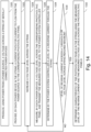
- FIG. 4 shows an example method performed by system 100 for capturing an image for electroluminescence analysis of photovoltaic panel 114, in instances where photovoltaic panel 114 is not producing power and power device 116 comprises diode 317 restricting reverse current for flowing toward the photovoltaic panel.
- a power system controller may determine to provide power, from a power source (e.g., power source 110), to a power device (e.g., power device 116) for electroluminescence imaging of a photovoltaic panel (photovoltaic panel 114).
- the determination may be the result of a user input requesting electroluminescence imaging, such as an input by an operator on a user interface of server (e.g., server 115) coupled to power system controller 104 (e.g., as may be described below in conjunction with Figure 8 ).
- the determination may be based on a measurement of irradiance level (e.g., as may be described below in conjunction with Figure 7 ).
- the photovoltaic panel may be connected to the power device.
- the power device may comprise a diode (e.g., diode 317) restricting current flow (e.g., reverse current) from the power source toward the photovoltaic panel.
- the power device may detect that it is receiving auxiliary power from the power source.
- power device 116 may receive auxiliary power from power source 110 via downstream terminals 312 and auxiliary power circuit 308.
- the power system controller 104 may initiate transmission of power from the power source 110 to the power device 116 in response to the indication received in step 400.
- the auxiliary power may enable the various modules and components of the power device 116 (e.g., power device controller 302, sensor(s) 306, gate driver 309, or power device communications interface 304) to operate regardless of whether the photovoltaic panel produces power or not.
- the power device 116 may receive an instruction to provide power to the photovoltaic panel in order to enable electroluminescence imaging of the panel.
- the instruction may be sent by the power system controller 104 , or from some other remote device (e.g., a server associated with a service provider).
- the instructions may be in the form of a voltage and/or current that the power system controller 104 provides to the power device (e.g., from power source 110 via terminals 118-1 and 118-2 to downstream terminals 312) as may be described in Figure 5 .
- the instructions may be in the form of a signal (e.g., received by power device 116 via power device communications interface 304) as may be described in Figure 6 .
- a controller of the power device 116 may cause performance of steps 402 through 404, as discussed below.
- the power device 116 may determine that the photovoltaic panel is not producing power. For example, as described in conjunction with Figures 5 and 6 below, the power device 116 may measure a voltage level between the upstream terminals (e.g., upstream terminals 310) to determine if the photovoltaic panel is producing power. In another example, the power device 116 may determine (e.g., based on a measurement of an irradiance level at or near the photovoltaic panel 114 by sensor(s) 306) that the photovoltaic panel is not producing power.
- the power device 116 may determine (e.g., based on a measurement of an irradiance level at or near the photovoltaic panel 114 by sensor(s) 306) that the photovoltaic panel is not producing power.
- the power device may control a switch (e.g., based on the determination that the photovoltaic panel is not producing power or based on the instruction received in step 401) to provide a current path from the power source to the photovoltaic panel.
- power device 116 may control switch 316 to transition to a conducting state, thereby providing a current path (e.g., which may bypass diode 317) from downstream terminals 312 to upstream terminals 310.
- a current path e.g., which may bypass diode 317
- current may flow from the power source 110 to the photovoltaic panel 114, and cause photovoltaic panel to emit radiation. This current flow may have the advantage of avoiding a restriction in reverse current flow imposed by the diode in the power device.
- the power system controller may control an imager to capture an image of the photovoltaic panel for electroluminescence analysis.
- power system controller 104 may control imager 108 to capture an image of the photovoltaic panel 114 either directly or wirelessly (e.g., via communications interface 206).
- a processor may analyze the captured image to determine a physical state of the photovoltaic panel.
- the processor may be, for example, processor 210 ( Figure 2 ) of power system controller 104, or a remote processor. Analysis of the captured image may comprise image segmentation and segment classification.
- the physical state may comprise one or more defects in the photovoltaic panel.
- the captured image may depict abnormalities in light or radiation emission from certain cells in a panel indicating cells failures, hot spots, and the like.
- an entity may initiate repair or replacement of the photovoltaic panel in response to determining the defects.
- step 404 may be omitted or may be performed before step 403.
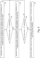
- the power device may measure (e.g., by sensor(s) 306) a first voltage level between a first terminal (e.g., first terminal 310-1) and a second terminal (e.g., 310-2) of a power device 116 (e.g., and of power converter 300) connected to a photovoltaic panel (e.g., photovoltaic panel 114).
- a first terminal e.g., first terminal 310-1
- a second terminal e.g., 310-2
- a power device 116 e.g., and of power converter 300
- This measurement may indicate if the photovoltaic panel is under low irradiance conditions and may not produce power, or under high illumination conditions and may be producing power.
- the power device 116 may determine (e.g., by power device controller 302) if the measured first voltage level is below a first threshold.
- This threshold of the voltage level may relate to the output voltage of the photovoltaic panel under low irradiance conditions. If the measured first voltage level is not below the first threshold, then the photovoltaic panel may be producing power (e.g., which may limit the ability to perform electroluminescence imaging) and the method may return to step 500. If the measured first voltage level is below the first threshold, than the photovoltaic panel may not be producing power (e.g., which may make electroluminescence imaging possible), and the method may proceed to step 504.
- the power device 116 may measure (e.g., by sensor(s) 306) a second voltage level between a third terminal (e.g., third terminal 312-1) and a fourth terminal (e.g., fourth terminal 312-2) of the power device 116 (e.g., and of power converter 300) connected to a power system controller (e.g., power system controller 104). This measurement may indicate to the power device that the power source (e.g., power source 110) may be providing power (e.g., via power system controller 104) for electroluminescence analysis.
- the power source e.g., power source 110
- the power source 110 may be providing power (e.g., via power system controller 104) for electroluminescence analysis.
- the power device may determine (e.g., by power device controller 302) if the measured second voltage level is above a second threshold. In a case where the measured second voltage level is not above a second threshold, then the power source may not be providing power to the power device 116, and the method may return to step 500. If the measured first voltage level is above the second threshold, then the power source may be providing power to the power device 116, and the method may proceed to step 508.
- the power device 116 may provide power (e.g., by power converter 300) from the downstream terminals (e.g., downstream terminals 312) to upstream terminals (e.g., upstream terminals 310).
- power device controller 302 may control switch 316 to transition to a conducting state, thus providing a path for current to flow from downstream terminals to the upstream terminals.
- the power converter may convert power (e.g., modify one or more of a voltage level and a current level) from the downstream terminals to the upstream terminals. Thus, reverse current may be provided to the corresponding photovoltaic panel of the power device.
- the power at the third terminal and the fourth terminal may be provided, for example, by power system controller 104, from power source 110. This power may also be used as auxiliary power for the power device 116.
- steps 500 and 502 may be omitted, and/or steps 504 and 506 may be performed before step 500 and 502.
- the power device 116 may measure (e.g., by sensor(s) 306) a first voltage level between a first terminal (e.g., first terminal 3 10-1) and a second terminal (e.g., 310-2) of the power device (e.g., and of power converter 300) connected to a photovoltaic panel (e.g., photovoltaic panel 114). This measurement may indicate if the photovoltaic panel is under low irradiance conditions and may not produce power, or under high illumination conditions and may be producing power.
- the power device 116 may determine (e.g., by power device controller 302) if the measured first voltage level is below a first threshold.
- This threshold of the voltage level may relate to the output voltage of the photovoltaic panel under low irradiance conditions.
- the photovoltaic panel may be producing power (e.g., which may limit the ability to perform electroluminescence imaging) and the method may return to step 600.
- the photovoltaic panel may not be producing power and the method may proceed to step 604.
- step 604 power device 116 may determine if a signal was received (e.g., by power device controller 302, via power device communications interface 304).
- the signal may be transmitted by the power system controller 104 (e.g., via communication interface 206).
- the signal may indicate to the power device that the power supply is providing power for electroluminescence imaging. If a signal was not received, the method returns to step 600. If a signal was received, the method may proceed to step 606.
- the power device 116 may provide power (e.g., by power converter 300) from downstream terminals (e.g., downstream terminals 312) to upstream terminals (e.g., upstream terminals 310).
- power device controller 302 may control switch 316 to transition to a conducting state, thus providing a path for current to flow from downstream terminals to the upstream terminals.
- the power converter may convert power (e.g., modify one or more of a voltage level and a current level) from the downstream terminals to the upstream terminals. Thus, reverse current may be provided to the corresponding photovoltaic panel of the power device.
- the power at the third terminal 118-1 and the fourth terminal 118-2 may be provided, for example, by converter 204, from power source 110. This power may also be used as auxiliary power for the power device 116.
- step 604 may be omitted or may be performed before step 602.
- the power device may measure (e.g., by sensor(s) 208) an irradiance level.
- the irradiance level may relate to a time of day and provide an indication if the photovoltaic panel or panels are producing power.
- the power device may determine (e.g., by central controller 202) if the measured irradiance level (e.g., from the sun) is below a threshold.
- a measured irradiance level above the threshold may correspond to a daylight irradiance level and may indicate that the photovoltaic panel or panels are producing power.
- a measured irradiance level below the threshold may correspond to a nighttime irradiance level and may indicate that the photovoltaic panel or panels are not producing power. If the measured irradiance level is not below a threshold, the method may return to step 700. If the measured irradiance level is below a threshold, the method may proceed to step 704.
- the power system controller 104 may provide power to the power device 116. This power may be employed by the power device as auxiliary power, and may be used for proving reverse current to the corresponding photovoltaic panel.
- the power system controller 104 may transmit (e.g., via communications interface 206) a signal to one or more power devices (e.g., power devices 116-1, 116-2, ..., 116-N).
- the signal may indicate to the power device or power devices that the power source is providing power for electroluminescence imaging purposes.
- power system controller 104 may transmit the signal as a unicast signal transmitted to one of the power devices 116, as a multicast signal to a group of power devices 116, or as a broadcast signal to all of power devices 116.
- the signal may comprise operational instructions to the power device 116.
- power system controller 104 may transmit a unicast signal to one of power devices 116 to provide a current path to the corresponding photovoltaic panel 114.
- Power system controller 104 may transmit a multicast signal to the other power devices 116 to short circuit their respective downstream terminals 312 (e.g., by transitioning switch 316 and second switch 906 ( Figures 9A and 9B ) to a conducting state, such as by transitioning switch 316 ( Figures 9C ) to a conducting state, or by transitioning switch 316 and switch 922 ( Figures 9D ) to a conducting state).
- Short circuiting downstream terminals 312 of the other power devices may allow reverse current to flow through the string (e.g., short circuiting bypass diodes 120 of the other power devices).
- the power system controller may control the imager (e.g., imager 108) to capture an image of the photovoltaic panel for electroluminescence analysis.
- step 706 may be omitted, and/or step 704 may be performed before step 700.
- the power system controller may receive an indication from a user via a user interface (e.g., user interface 216).
- a user interface e.g., user interface 216
- the user may provide the user indication if the user determines that electroluminescence analysis is to be performed on the photovoltaic panels.
- the user may provide the user indication via user interface 216.
- the power system controller may provide power from a power source (e.g., power source 110) to a power device 116.
- the power device 116 may employ this power as auxiliary power to operate one or more circuits (e.g., controller, gate-drivers, sensors, etc.).
- the power device 116 may provide the power to a photovoltaic panel coupled to its input terminals.
- the power device may provide a reverse current to the corresponding photovoltaic panel.
- the power system controller may transmit (e.g., via communications interface 206) a signal to one or more power devices (116-1, 116-2, ..., 116-N).
- the signal may indicate to the power devices that the power source is providing power for electroluminescence imaging purposes.
- the power device may provide reverse current to the respective photovoltaic panel based on receiving this signal.
- the power system controller may control the imager (e.g., imager 108) to capture an image (e.g., by imager 108) of the photovoltaic panel for electroluminescence analysis.
- step 804 may be performed before step 802.
- the power device may comprise a power converter that includes a diode that restricts reverse current from flowing to the corresponding photovoltaic panel of the power device.
- Figures 9A-9E show various examples of a power converter 300 according to aspects of the disclosure herein.
- Figures 9A-9D illustrate examples of DC-DC converters
- Figure 9E illustrates an example of a DC-AC converter (e.g., an inverter or a microinverter).
- power converter 300 may be a bi-directional converter, which may convert power from first (upstream) terminals 310 to second (downstream) terminal 312 and/or convert power from downstream terminals 312 to upstream terminals 310.
- power converter 300 may modify (e.g., increase or decrease) one or more of a voltage and a current, based on a duty cycle of a pulse width modulation (PWM) signal.
- PWM pulse width modulation
- power converter 300 may comprise switch 316, a second switch 906, an inductor 908, a first capacitor 902, and/or a second capacitor 904.
- the switches are shown as Metal Oxide Semiconductor Field Effect Transistors (MOSFETs), but any suitable switch or transistor may be used (e.g., Bipolar Junction Transistor (BJT), Insulated Gate Bipolar Transistor (IGBT), Gallium Nitride (Gan) Transistors, Silicon Carbide (SiC) MOSFETS, Thyristor, etc.).
- a source of switch 316 may be connected to a drain of second switch 906 at a connection point 910.
- Inductor 908 may be connected between first terminal 310-1 and connection point 910.
- First capacitor 902 may be connected between first terminal 310-1 and second terminal 310-2.
- Second capacitor 904 may be connected between third terminal 312-1 and fourth terminal 312-2.
- Second terminal 310-2 and fourth terminal 312-2 may be connected to each other.
- diode 317 of switch 316 may restrict current from flowing from third terminal 312-1 toward first terminal 310-1 where switch 316 is in a non-conducting state (e.g., switch 316 does not enable current to flow from the drain to the source of switch 316).
- Figure 9A shows an example in which power converter 300 may operate as a synchronous boost converter when converting power from first (upstream) terminals 310 to second (downstream) terminals 312.
- Power converter 300 may operate as a synchronous buck converter when converting power from downstream terminals 312 to upstream terminals 310.
- Converter 300 may use a PWM signal to control the states of switches 316 and 906.
- the voltage level at downstream terminals 312 may be related to the voltage level at upstream terminals 310 by a factor of 1/1-D1, where D1 is a first duty cycle (e.g., a value between 0 and 1) of the PWM signal.
- D1 is a first duty cycle (e.g., a value between 0 and 1) of the PWM signal.
- the voltage level at upstream terminals 310 may be related to voltage levels at downstream terminals 312 by D2, where D2 is a second duty cycle of the PWM signal, which may be the same as, or different from, D1.
- Figure 9B shows an example in which power converter 300 may operate as a synchronous buck and boost converter and may comprise a switch 316, a second switch 906, a third switch 912, a fourth switch 914, an inductor 908, a first capacitor 902, or a second capacitor 904.
- third switch 912 and fourth switch 914 are shown as MOSFETs, but any suitable switch or transistor could be used (e.g., Bipolar Junction Transistor (BJT), Insulated Gate Bipolar Transistor (IGBT), Gallium Nitride (Gan) Transistors, Silicon Carbide (SiC) MOSFETS, Thyristor, etc.).
- BJT Bipolar Junction Transistor
- IGBT Insulated Gate Bipolar Transistor
- GaN Gallium Nitride
- SiC Silicon Carbide
- the source of switch 316 may be connected to the drain of the second switch 906 at a connection point 910.
- a source of third switch 912 may be connected to a drain of the fourth switch 914 at a connection point 916.
- the drain of third switch 912 may be connected to first terminal 310-1.
- the drain of switch 316 may be connected to third terminal 312-1.
- Inductor 908 may be connected between connection point 910 and connection point 916.
- First capacitor 902 may be connected between first terminal 310-1 and second terminal 310-2.
- Second capacitor 904 may be connected between third terminals 312-1 and fourth terminal 312-2. Second terminal 310-2 and fourth terminal 312-2 may be connected to each other. Similar to as shown in Figure 9A , in Figure 9B , diode 317 of switch 316 may restrict current from flowing from third terminal 312-1 toward first terminal 310-1 when switch 316 is in a non-conducting state.
- Power converter 300 when comprising a synchronous buck and boost converter, may be used as either a buck converter, a boost converter, or a buck-boost converter, either when converting power from upstream terminals 310 to downstream terminals 312, or from downstream terminals 312 to upstream terminals 310.
- power device controller 302 controls power converter 300 as a buck-boost converter to convert power from upstream terminals 310 to downstream terminals 312 using a PWM signal
- the voltage level at downstream terminals 312 may be related to the voltage level at upstream terminals 310 by a factor D3/(1-D3), where D3 is a duty cycle of the PWM signal.
- the voltage level at upstream terminals 310 may be related to the voltage level at downstream terminals 312 by a factor D4/(1-D4), where D4 is a duty cycle of the PWM signal.
- FIG. 9C shows an example in which power converter 300 may comprise a synchronous flyback converter, which may be an isolated non-inverting buck-boost converter.
- Power converter 300 comprising a synchronous flyback converter may comprise a switch 316, a second switch 918, a coupled inductor 920, a first capacitor 902 and a second capacitor 904.
- second switch 918 is also shown as a MOSFET, though any suitable switch or transistor may be used (e.g., Bipolar Junction Transistor (BJT), Insulated Gate Bipolar Transistor (IGBT), Gallium Nitride (Gan) Transistors, Silicon Carbide (SiC) MOSFETS, Thyristor, etc.).
- BJT Bipolar Junction Transistor
- IGBT Insulated Gate Bipolar Transistor
- GaN Gallium Nitride
- SiC Silicon Carbide
- the primary side windings of coupled inductor 920 may be connected between the drain of second switch 918 and first terminal 310-1.
- the source of second switch 918 may be connected to second terminal 310-2.
- the secondary side windings of coupled inductor 920 may be connected between the source of switch 316 and fourth terminal 312-2.
- the drain of switch 316 may be connected to third terminal 312-1.
- First capacitor 902 may be connected between first terminal 310-1 and second terminal 310-2.
- Second capacitor 904 may be connected between third terminal 312-1 and fourth terminal 312-2. Similar to as shown in Figures 9A and 9B , diode 317 of switch 316 in Figure 9C may restrict current from flowing from third terminal 312-1 toward first terminal 310-1 if switch 316 is in a non-conducting state.
- the voltage level at downstream terminals 312 may be related to the voltage level at upstream terminals 310 by a factor of (n*D5)/(1-D5), where D5 is a duty cycle of the PWM signal and n is a turns ratio of coupled inductor 920 (e.g., a ratio between the number of turns in secondary side of coupled inductor 920, and the number of turns in the primary side of coupled inductor 920).
- Converter 300 operates (e.g., as controlled by power device controller 302) to convert power from downstream terminals 312 to upstream terminals 310 using a PWM signal, the voltage level at upstream terminals 310 may be related to the voltage level at downstream terminals 312 by a factor D6/n*(1-D6), where D6 is a duty cycle of the PWM signal.
- Figure 9D shows an example of power converter 300 comprising a synchronous Dual Single-Ended Primary-Inductor (Dual SEPIC) converter, which may be a non-inverting buck-boost converter.
- Power converter 300 comprising a synchronous Dual-SEPIC converter may comprise switch 316, a second switch 922, a first inductor 908, a second inductor 926, a first capacitor 902, a second capacitor 904 and a third capacitor 928.
- second switch 922 is also shown as a MOSFET, though any suitable switch or transistor could be used (e.g., Bipolar Junction Transistor (BJT), Insulated Gate Bipolar Transistor (IGBT), Gallium Nitride (Gan) Transistors, Silicon Carbide (SiC) MOSFETS, Thyristor, etc.).
- BJT Bipolar Junction Transistor
- IGBT Insulated Gate Bipolar Transistor
- Ga Gallium Nitride
- SiC Silicon Carbide
- Thyristor Thyristor, etc.
- the source of switch 316 may be connected to connection point 924, and the drain of switch 316 may be connected to third terminal 312-1.
- the drain of second switch 922 may be connected to connection point 910, and the source of second switch 922 may be connected to second terminal 310-2.
- Third capacitor 928 may be connected between connection points 910 and 924.
- First inductor 908 may be connected between connection point 910 and first terminal 310-1.
- Second inductor 926 may be connected between connection point 924 and fourth terminal 312-2.
- First capacitor 902 may be connected between first terminal 310-1 and second terminal 310-2.
- Second capacitor 904 may be connected between third terminals 312-1 and fourth terminal 312-2.
- Second terminal 310-2 and fourth terminal 312-2 may be connected to each other. Similar to as shown in Figure 9A, 9B , and 9C , in Figure 9D , diode 317 of switch 316 may restrict current from flowing from third terminal 312-1 toward first terminal 310-1 if switch 316 is in a non-conducting state.
- Dual SEPIC converter 300 may operate (e.g., as controlled by power device controller 302) to convert power from upstream terminals 310 to downstream terminals 312 using a PWM signal, the voltage level at downstream terminals 312 may be related to the voltage level at upstream terminals 310 by a factor D7/(1-D7), where D7 is a duty cycle of the PWM signal.
- Converter 300 may operate (e.g., as controlled by power device controller 302) to convert power from downstream terminals 312 to upstream terminals 310 using a PWM signal, the voltage level at upstream terminals 310 may be related to the voltage level at downstream terminals 312 by a factor D8/(1-D8), where D8 is a duty cycle of the PWM signal.
- Power converter 300 comprising a DC-AC inverter 901 may comprise a DC-AC inverter 930, a transformer 932, an AC-AC converter 934, a first capacitor 902, and/or a second capacitor 904.
- DC-AC inverter 930 may comprise, for example, a half-bridge or a full-bridge converter, a Neutral Point Clamped converter, a flying capacitor converter, or the like.
- AC-AC converter 934 may be configured to modulate the frequency of an AC power waveform.
- AC-AC converter 934 may comprise switch 316, which may comprise diode 317.
- DC-AC inverter 930 may be connected to first terminal 310-1 and second terminal 310-2.
- AC-AC converter 934 may be connected to third terminal 312-1 and fourth terminal 312-2.
- Transformer 932 may be connected to DC-AC inverter 930 and to AC-AC converter 934.
- First capacitor 902 may be connected between first terminal 310-1 and second terminal 310-2.
- Second capacitor 904 may be connected between third terminals 312-1 and fourth terminal 312-2.
- DC-AC inverter 930 may receive DC power at first terminal 310-1 and second terminal 310-2, and may convert the DC power to a first AC power waveform having a first frequency.
- transformer 932 may be a step-up transformer, in which the number of windings in the secondary windings may be larger than the number of windings in the primary windings.
- the voltage level at the secondary side may be larger (e.g., stepped-up) than the value of the voltage and the primary side.
- AC-AC converter 934 may convert the first AC power (e.g., stepped-up) waveform to a second AC power waveform having a second frequency, which may be different (e.g., lower or higher) from the first frequency.
- the second AC power waveform may be on the order of tens of Hertz.
- Producing a first AC power waveform with a frequency higher frequency may enable a reduction in the size of transformer 932 (e.g., the size of a transformer may be inversely proportional to the frequency of the first AC waveform).
- diode 317 of switch 316 may restrict current from flowing from third terminal 312-1 to first terminal 310-1 when switch 316 is in a non-conducting state.
- power converter 300 may be a bi-directional converter, which may convert power from upstream terminals 310 to downstream terminals 312, or from downstream terminals 312 to upstream terminals 310.
- the conversion ratio between the voltages when power converter 300 converts power from upstream terminals 310 to downstream terminals 312 may be different from the conversion ratio between the voltage levels when power converter 300 converts power from downstream terminals 312 to upstream terminals 310.
- power converter 300 may convert power from upstream terminals 310 to downstream terminals 312, where the voltage level at upstream terminals 310 may be 36 volts and the voltage level at downstream terminals 312 may be 100V.
- Power converter 300 may convert power from downstream terminals 312 to upstream terminals 310, where the voltage level at downstream terminals 312 may be 90 volts and the voltage level at first terminal 310 may be 24V. It is noted that the numerical examples are non-limiting and are brought herein for the sake of clarity of the explanation. Other numbers or ratios may be employed.
- power device controller 302 may control parameters when power converter 300 converts power from upstream terminals 310 to downstream terminals 312, that are different from the parameters when power converter 300 converts power from downstream terminals 312 to upstream terminals 310.
- the controlled parameter may be one or more of the voltage level at upstream terminals 310, and the voltage level at downstream terminals 312.
- the controlled parameter may be one or more of the current level through first terminal 310-1, second terminal 310-2, third terminal 312-1, or fourth terminal 312-2.
- power device controller 302 may employ the current through first terminal 310-1 as the controlled parameter.
- power device controller 302 may employ the voltage at upstream terminals 310 as the controlled parameter.
- a power device 116 may include a bypass circuit, which may provide a path for reverse current to follow to the corresponding photovoltaic panel.
- a bypass circuit may be useful in non-synchronous converters where the diode is not connected to a switch (e.g., a non-synchronous boost converter) or in DC isolated converters, such as those in Figures 9C-9E .
- the bypass circuit may comprise a switch or switches which may be controlled by power device controller 302, or may operate independently.
- Figures 10A-10B , 11A-11C , and 12A-11B show examples of such bypass circuits.
- FIGS 10A and 10B show a power device 116, which may comprise a bypass circuit 1000 connected to power device controller 302.
- auxiliary power circuit 308 may receive power from first terminal 310-1 and second terminal 310-2, or from third terminal 312-1 and fourth terminal 312-2, or from both.
- Power device controller 302 may control bypass circuit 1000, (e.g., by generating a control signal) to create a current path between third terminal 312-1 and first terminal 310-1 (e.g., enabling current to flow to the photovoltaic panel, for example, for an electroluminescence test).
- Power device controller 302 may control bypass circuit 1000 based on one or more of a measured voltage between third terminal 312-1, a fourth terminal 312-2, and based on a received signal (e.g., similar to as described above in conjunction with Figures 4 ).
- Figure 10B shows an example of bypass circuit 1000 which may be controlled by power device controller 302.
- bypass circuit 1000 is shown as comprising two N-type MOSFETs switches 1002-1 and 1002-2, but any suitable switch or transistor may be used.
- the drain of switch 1002-1 may be connected to the drain of switch 1002-2.
- the source of switch 1002-1 may be connected to first terminal 310-1 and the source of switch 1002-2 may be connected to third terminal 312-1.
- the gates of switches 1002-1 and 1002-2 may be connected to power device controller 302.
- bypass circuit is shown as including two switches (e.g., switch 1002-1 and switch 1002-2). It is noted that bypass circuit 1000 may include one or more additional components such as resistors (e.g., a resistor divider), capacitors, inductors, and diodes.
- resistors e.g., a resistor divider
- capacitors e.g., inductors, and diodes.
- FIGS 11A, 11B and 11C show examples of a power device 116, which may comprise a bypass circuit 1100.
- auxiliary power circuit 308 may receive power from first terminal 310-1 and second terminal 310-2 only.
- Bypass circuit 1100 may operate independently (e.g., independent of power device controller 302), to create a current path between third terminal 312-1 and first terminal 310-1).
- bypass circuit may create a current path between third terminal 312-1 and first terminal 310-1.
- Figure 11B shows an example of bypass circuit 1100, which may comprise N-type MOSFET switch 1102 and a P-type MOSFET switch 1104, but any suitable switch or transistor may be used.
- the source of switch 1102 may be connected to the drain of switch 1104.
- the drain and gate of switch 1102 may be connected to third terminal 312-1.
- the source and gate of switch 1104 may be connected to first terminal 310-1.
- switch 1102 and switch 1104 When the voltage level between third terminal 312-1 and first terminal 310-1 is below a first threshold, switch 1102 and switch 1104 may be in a non-conducting state, thereby blocking a current path between third terminal 312-1 and first terminal 310-1. When the voltage level between third terminal 312-1 and first terminal 310-1is above or increases above a second threshold, switch 1102 and switch 1104 may be in or transition to, respectively, a conducting state, thus creating a current path between third terminal 312-1 and first terminal 310-1.
- the first threshold and the second threshold may be the same, or they may be different.
- FIG. 11C shows another example of bypass circuit 1100, which may comprise a diode for alternating current (DIAC) (also referred to as a diode AC switch) 1106 and a diode 1108.
- the anode of diode 1108 may be connected to one terminal (e.g., Main Terminal 2 (MT2)) of DIAC 1106.
- the cathode of diode 1108 may be connected to first terminal 310-1.
- the other terminal (e.g., MT1) of DIAC 1106 may be connected to third terminal 312-1.
- DIAC 1106, and consequently diode 1108 may be come conductive, thus creating a current path between third terminal 312-1 and first terminal 310-1.
- bypass circuit 1100 may include one or more additional components other than the components described in Figures 11A-11C .
- additional components may be resistors (e.g., a resistor divider), capacitors, inductors, and diodes.
- FIGS 12A and 12B show a power device 116, which may comprise a bypass circuit 1200 connected to comparator circuit 1202 for determining if power is provided by power system controller 104 (e.g., from power source 110) at downstream terminals 312.
- power system controller 104 e.g., from power source 110
- Bypass circuit 1200 may be similar to bypass circuit 1000 ( Figure 10B ).
- Comparator circuit 1202 may compare the voltage level between third terminal 312-1 and first terminal 310-1 and control bypass circuit 1200 to create a current path between third terminal 312-1 and first terminal 310-1 (e.g., based on the voltage level between third terminal 312-1 and first terminal 310-1 exceeding a threshold).
- Figure 12B shows an example of comparator circuit which may be used to control bypass circuit 1200.
- Comparator circuit 1202 may comprise a comparator 1204, a diode 1206 and a capacitor 1208.
- Comparator circuit 1202 optionally comprises a voltage divider 1210. Diode 1206 and capacitor 1208 may form a bootstrap power supply for providing auxiliary power for comparator 1204.
- Capacitor 1208 may be connected to first terminal 310-1, to the negative supply terminal, Vs-, of comparator 1204, and to the cathode of diode 1206.
- the cathode of diode 1206 may be connected to the positive supply terminal, Vs+, of comparator 1204.
- the anode of diode 1206 may be connected to third terminal 312-1.
- Third terminal 312-1 may be connected to the positive input of comparator 1204, optionally, via voltage divider 1210.
- Voltage divider 210 may be connected between third terminal 312-1 and fourth terminal 312-2.
- the negative input of comparator 1204 may be connected to first terminal 310-1.
- capacitor 1208 may charge via diode 1206, thereby providing power for comparator 1204 to operate.
- Comparator 1204 may compare the voltage at the positive input with the voltage at the negative input, and may control bypass circuit 1200 to create a current path between third terminal 312-1 and first terminal 310-1 (e.g., based on the voltage at the positive input being higher than the voltage at the negative input).
- comparator circuit 1202 is power from downstream terminals 312, the power devices 116-N may use auxiliary power circuit 308 may receive power from upstream terminals 310 only (e.g., as in normal operation when photovoltaic panel 114 produces power).
- a power device may comprise an auxiliary power circuit (e.g., auxiliary power circuit 308 - Figures 3A-3C ), which may receive power either from a photovoltaic panel (photovoltaic panel 114-N - Figures 1A-1C ), from a power source via power system controller (e.g., power source 110 via power system controller 106 - Figures 1A-1C ), or from both.
- auxiliary power circuit e.g., auxiliary power circuit 308 - Figures 3A-3C
- a power device with such an auxiliary power circuit may be used to characterize and/or determine the physical state of a photovoltaic panel (e.g., with electroluminescence analysis).
- characterizing a photovoltaic panel may include determining an I-V curve corresponding to the photovoltaic panel or determining parameters of a model corresponding to the photovoltaic panel. Such parameters may be open circuit voltage (Voc), shout circuit current (Isc), shunt resistance (Rsh), series resistant (Rsr), fill factor (FF) to name a few.
- Characterizing a photovoltaic panel may aid in determining the physical, electrical, and functional properties of the panel. For example, characterizing a photovoltaic panel may aid in determining a degradation of the photovoltaic panel over time.
- determining an I-V curve of a photovoltaic panel during times in which the photovoltaic panel produces power may be challenging, since determining an I-V curve requires changing both the voltage level across, and the current level through the photovoltaic panel (e.g., which may affect the power produced by the photovoltaic panel). Also, determining an I-V curve of a photovoltaic panel during times in which the photovoltaic panel produces power may be affected by the temperature of the photovoltaic panel. In some cases, it may be possible to characterize a photovoltaic panel, when the photovoltaic panel does not produce power (e.g., during low irradiation conditions) using a reverse current. As mentioned above, an I-V curve determined when the photovoltaic panel does not produce power may be referred to as a "dark I-V curve".
- a power device 116-N such as described above in conjunction with Figures 1A-1C & 3A , 10A, 10B , 11A, 11B , 12A, 12B may be used to perform dark I-V curve measurements of a photovoltaic panel. It is noted that performing dark I-V curve measurements may be performed with power devices which may comprise a power converter (e.g., a buck converter) that does not have a diode restricting current flowing toward the photovoltaic panel.
- a power converter e.g., a buck converter
- Figure 13A (and also referring to Figures 1A-1C , 2 & 3A , 10A, 10B , 11A, 11B , 12A, 12B ), which may show aspects of system 100 ( Figure 1A ), where power devices 116-1, 116-2, ..., 116-N may be connected in a series string.
- string 112 is shown to have three power devices 116-1, 116-2, and 116-3, and corresponding photovoltaic panels 114-1, 114-2, and 114-3, though any number of power devices and panels may be included.
- power system controller 104 may receive power from power source 110, and provide this power at terminals 118-1 and 118-2 (e.g., using power converter 204 - Figure 2 ). For example, power system controller 104 may produce a voltage, VDC, between terminals 118-1 and 118-2, such that a current may be drawn from power system controller 104 (as further elaborated below).
- a corresponding voltage, VO-n may develop across third terminal 312-1 and fourth terminal 312-2 of each of corresponding power device 116-N of power devices 116-1, 116-2, ..., 116-N.
- the corresponding auxiliary power circuit 308 may be configured to provide power to the various modules of power device 116-N (e.g., power device controller 302, power device communications interface 304, sensor(s) 306 to name a few).
- power device controller 302 of each of corresponding power devices 116-1 - 116-3 may control the corresponding switch 316 (e.g., of Figures 9A-9E ) to a conducting state. Controlling switch 316 of each power device 116-1 - 116-3 to a conducting state may enable a reverse current to flow from the third terminal 312-1 to first terminal 310-1, through photovoltaic panel 114, and from second terminal 310-2 to fourth terminal 312-2.
- transitioning switch 316 to a conducting state may couple third terminal 312-1 to first terminal 310-1, and second terminal 310-2 is coupled to fourth terminal 312-2, the voltage, VO-n, between third terminal 312-1 and fourth terminal 312-2 is the same as the voltage, VP-n, between first terminal 310-1 and second terminal 310-2.
- each level of VDC produced by power system controller 104 may result in a different level IS and thus different levels of VO-n's (and thus a different level of VP-n's).
- the combination of IS and VP-n may correspond to a point on the dark I-V curve of the corresponding photovoltaic panel 114-1 - 114-3.
- Figures 13A and 13B which show three dark I-V curves 1300-1, 1300-2, and 1300-3.
- Power system controller 104 may produce a voltage, VDC, between terminals 118-1 and 118-2, at a first level. This first level of VDC may result in a reverse string current, IS, of a level I_1 flowing through photovoltaic panels 114-1, 114-2, and 114-3.
- the first level of VDC may result in a voltage V1-1 across panel 114-1 (across corresponding first terminal 310-1 and second terminal 310-2), a voltage V1-2 across panel 114-2, and a voltage V1-3 across panel 114-3.
- the combination of I_1 and V1-1 corresponds to a point on dark I-V curve 1300-1 of panel 114-1.
- the combination of I_1 and V1-2 corresponds to a point on dark I-V curve 1300-2 of panel 114-2.
- the combination of I_1 and V1-3 corresponds to a point on dark I-V curve 1300-3 of panel 114-3.
- Power system controller 104 may increase VDC to a second level, which may result in a reverse string current, IS, of a level I_2.
- the second level of VDC may result in a voltage V2-1 across panel 114-1, a voltage V2-2 across panel 114-2, and a voltage V2-3 across panel 114-3.
- the combination of I_2 and V2-1 corresponds to a second point on dark I-V curve 1300-1 of panel 114-1.
- the combination of I_2 and V2-2 corresponds to a second point on dark I-V curve 1300-2 of panel 114-2.
- the combination of I_2 and V2-3 corresponds to a second point on dark I-V curve 1300-3 of panel 114-3.
- Power system controller 104 may increase VDC to various levels, for example, until the reverse string current, IS, reaches a maximum level, where each level results in a power point (voltage and current) on a dark I-V curve 1300-1, 1300-2, and 1300-3, corresponding to photovoltaic panels 114-1 - 114-3, respectively. Power system controller 104 may increase VDC to various levels until a maximum power level of power system controller 104 is reached.
- each of dark I-V curves 1300-1, 1300-2 and 1300-3 may be sampled with a plurality of combinations of VP-n's and IP-n's, where IP-n is a reverse current through the corresponding photovoltaic panel 114-n (which may be equal to IS in the example shown in Figures 13A and 13B ).
- sensor(s) 306 of each of power devices 116-1 - 116-3 may measure the corresponding VO-n or VP-n. Sensors(s) 306 of each of power devices 116-1 - 116-3, or sensor(s) 208 of power system controller 104 may measure the reverse string current IS. Power devices 116-1 - 116-3 may transmit the corresponding measurements to power system controller 104, using the corresponding power device communications interface 304, for example, to central controller 202. Using central controller 202 ( Figure 2 ), power system controller 104 may determine various characteristics of photovoltaic panels 114-1 - 114-3, based on the received measurements from power devices 116-1 - 116-3.
- power system controller 104 may fit corresponding curves to the received measurements (e.g., samples) from power devices photovoltaic panels 116-1 - 116-3 and determine characteristics of the corresponding photovoltaic panels 114-1 - 114-3 using these curves.
- FIG. 14 shows a method for characterizing photovoltaic panels in a string.
- step 1320 power from power source 110 is produced, resulting in a voltage being generated across a string 112 of serially connected power devices 116-1 - 116-N.
- power system controller 104 may produce (e.g., using power converter 204 - Figure 2 ) a voltage across string 112 using power from power source 110.
- the string may include a single power device 116 or multiple power devices 116.
- Step 1322 includes providing, e.g., by each power device of power devices 116-1 - 116-N in string 112, a current path for current to flow to a corresponding photovoltaic panel 114-1 - 114-N.
- power device controller 302 of each of power devices 116-1 - 116-N may control switch 316 of the corresponding power converter 300 to a conducting state. Controlling switch 316 to a conducting state may enable a reverse current to flow from the third terminal 312-1 to first terminal 310-1, through photovoltaic panel 114, and from second terminal 310-2 to fourth terminal 312-2.
- determining a dark I-V curve may be performed with power devices which may comprise power converter (e.g., buck converters) which do not have a diode restricting current flowing toward the photovoltaic panel.
- power converter e.g., buck converters
- step 1322 is optional.
- Step 1324 increase the voltage level across string 112.
- power source 110 may be configured to increase the voltage level across string 112.
- power system controller 104 may increase the voltage level across string 112 using power from power source 110 and power converter 204 ( Figure 2 ).
- Step 1326 includes measuring, e.g., by each power device of power device 116-1 - 116-N, using the corresponding sensor(s) 306, a voltage level (VP-i) across the corresponding photovoltaic panel (e.g., across first terminal 310-1 and second terminal 310-2), and transmit, using power device communications interface 304, the measured voltage level to the power system controller 104.
- VP-i voltage level across the corresponding photovoltaic panel
- Step 1328 includes determining, e.g., by power system controller 104, a level of the reverse current (IS) through the string.
- power system controller 104 may measure, using sensor(s) 208 ( Figure 2 ) a level of the reverse current (IS) through the string.
- each power device of power devices 116-1 - 116-N may measure the level of IS (e.g., using sensor(s) 306) and transmit (e.g., using power device communications interface 304) the measurements of IS to the power system controller 104.
- Power system controller 104 may determine IS based on the received measurements.
- Step 1330 includes determining, e.g., by power system controller 104 (e.g., using sensor(s) 208), if the level of the reverse current exceeds a threshold, or if the voltage level across string 112 reached a maximum. In cases in which the level of the reverse current did not exceed a threshold, or the voltage level across string 112 did not reach a maximum the method may return to step 1324. In cases in which the level of the reverse current exceeds a threshold, or if the voltage level across string 112 reaches a maximum, the method may proceed to step 1332.
- Step 1332 includes determining, e.g., for example by power system controller 104 (e.g., using processor 210), a characteristic of the photovoltaic panels in string 112 using the measured level of the reverse current and the measured voltage levels across the photovoltaic panels. Determining a characteristic of a photovoltaic panel 114-N may comprise determining an I-V curve corresponding photovoltaic panel 114-N. Determining a characteristic of a photovoltaic panel 114-N may comprise determining electrical parameters (e.g., Rsh, Rs, Voc, etc.) corresponding to photovoltaic panel 114-N.
- electrical parameters e.g., Rsh, Rs, Voc, etc.
- the dark I-V curves of some of photovoltaic panels 114-1 -114-N may not be sufficiently sampled to characterize the photovoltaic panels.
- curve 1300-1 may not be sufficiently sampled to characterize the photovoltaic panel 114-1.
- string 112 comprises a large number of photovoltaic panels 114-1 -114-N. In such cases, the voltage division of VDC between photovoltaic panels 114-1 -114-N may render the highest voltage at each photovoltaic panel lower than required to characterize the panel.
- each of power devices 116-1 - 116-N may use the corresponding power converter 300 to convert power from third terminal 312-1 and fourth terminal 312-2, to first terminal 310-1 and second terminal 310-2.
- each photovoltaic panel may be characterized using points having different voltages and currents on the corresponding dark I-V curve as further elaborated below.
- Figure 15A shows aspects of system 100 described herein above in conjunction with Figure 1A , where power devices 116-1, 116-2, ..., 116-N may be connected in series string 112.
- string 112 is shown to have three power devices 116-1, 116-2, and 116-3, and corresponding photovoltaic panels 114-1, 114-2, and 114-3, though the system could include any number of power devices and panels.
- power system controller 104 may use power from power source 110 and produce power at terminals 118-1 and 118-2 (e.g., using power converter 204 - Figure 2 ).
- power system controller 104 may produce a voltage, VDC, between terminals 118-1 and 118-2, such that a current may be drawn from power system controller 104.
- VDC voltage between terminals 118-1 and 118-2
- a corresponding voltage, VO-n may develop across third terminal 312-1 and fourth terminal 312-2 of each corresponding power device 116-N of power devices 116-1 - 116-3.
- the corresponding auxiliary power circuit 308 may be configured to provide power to the various modules of power device 116-N.
- power system controller 104 may use power from power source 110 and may produce VDC at a determined level.
- Power system controller 104 may transmit, using communications interface 206 a signal corresponding to a power level, Pn, to each of power devices 116-1 - 116-3.
- the reverse string current, IS is defined by the total power from power system controller 104 and VDC.
- the power, Pn, converted by power device 116-N, is determined by power system controller 104.
- Pn is also the power provided to photovoltaic panel.
- power system controller 104 may sample the dark I-V curves of the corresponding photovoltaic panels 114-1 - 114-3 at a plurality of different points.
- Figures 15A and 15B may show three dark I-V curves 1340-1, 1340-2, and 1340-3.
- Dark I-V curve 1340-1 corresponds to photovoltaic panel 114-1
- dark I-V curve 1340-2 corresponds to photovoltaic panel 114-2
- dark I-V curve 1340-3 corresponds to photovoltaic panel 114-3.
- power system controller 104 transmits power levels P1-1, P1-2, and P1-3 to power devices 116-1-116-3 respectively.
- Each of power devices 116-1-116-3 receives corresponding power levels, and convert the received power levels to corresponding Ips and VPs equal to the received power levels.
- each of power devices 116-1-116-3 may measure the levels of the corresponding VP-n and IP-n (e.g., using sensor(s) 306) and transmit (e.g., using power device communications interface 304) the measurements to power system controller 104.
- power system controller 104 may transmit power levels P2-1, P2-2, and P2-3 to and P3-1, P3-2, and P3-3 to power devices 116-1-116-3.
- power system controller 104 may determine that the reverse current for the corresponding panel (e.g., IP-3 through photovoltaic panel 114-3) reached a maximum level. Therefore, power system controller 104 may maintain the power level transmitted to power device 116-3 at P3-3 or reduce the power level transmitted to power device 116-3.
- Power system controller 104 may proceed and transmit higher power levels to the remaining power devices, such as transmitting P4-1 and P4-2 to power devices 116-1 and 116-2. After receiving the measurements corresponding to P4-2 from power device 116-2, power system controller 104 may determine that the reverse current IP-2 through photovoltaic panel 114-2 reached a maximum level. Therefore, power system controller 104 may maintain the power level transmitted to power device 116-2 at P4-2 or reduce the power level transmitted to power device 116-2. Power system controller 104 may proceed and transmit power levels P5-1 to power device 116-1, where the reverse current IP-1 may also reach a maximum.
- power system controller 104 may sample dark I-V curves 1340-1, 1340-2 and, 1340-3, and use these samples to characterize the corresponding photovoltaic panels 114-1 - 114-3.
- power system controller may enable the other power devices to continue and sample the corresponding dark I-V curves, where the only constraint is that the some of the power levels, Pn's, is equal or smaller than the maximum power, power system controller 104 may produce.
- step 1350 produce, using power from power source 110, a voltage across string 112 of serially connected power devices 116-1 - 116-N.
- power system controller 104 may produce a voltage across string 112 using power from power source 110.
- Step 1352 includes transmitting, e.g., by the power system controller 104, to power devices 116-1 - 1161-N in the string 112, signals corresponding power levels for photovoltaic panel characterization of photovoltaic panels 114-1-114-N.
- the corresponding power levels transmitted by power system controller 104 to power devices 116-1 - 1161-N need not be equal.
- power system controller 104 may transmit power levels P1-1-P5-1 to power device 116-1, power levels P1-2-P4-2 to power device 116-2, and power levels P1-3-P3-3 to power device 116-3.
- Step 1354 includes, responsive to the voltage across string 112, converting by each power device of power devices 116-1-116-N (e.g., using power converter 300), a power level of the plurality of power levels for the corresponding photovoltaic panel 114-N.
- the power converted by power device 116-N may have a corresponding voltage, VP-n, across photovoltaic panel 114-N, and a corresponding reverse current IP-n through photovoltaic panel 114-N.
- VP-n and IP-n may define a point on the corresponding dark I-V curve of photovoltaic panel 114-N.
- Step 1356 includes measuring, e.g., by each of power devices 116-1-116-N (e.g., using sensor(s) 306), a voltage level across the corresponding one of photovoltaic panels 114-1-114-N and a reverse current level through the corresponding one of photovoltaic panels 114-1-114-N.
- the voltage level across photovoltaic panel 114-N may be measured by measuring the voltage level between first and second terminals 310-1 and 310-2.
- a current through photovoltaic panel 114-N may be measured by measuring a current through one of first terminal 310-1 or second terminal 310-2.
- Step 1358 incudes characterizing the photovoltaic panel using the corresponding measured voltage levels and corresponding measured current levels. Characterizing the photovoltaic panel may be performed by the corresponding one of power devices 116-1-116-N. Characterizing the photovoltaic panels may be performed by power system controller 104.
- Step 1370 includes receiving, e.g., by a power device 116-N of power devices 116-1-116-N, and responsive to a voltage across output terminals of the power device, signals corresponding to a plurality of power levels.
- the received power levels may be stored in memory 316.
- a power device 116-N may receive the plurality of power levels from power system controller 104 via power device communications interface 304 ( Figure 3A ).
- power device 116-1 may receive power levels P1-1 to P5-1
- power device 116-2 may receive power levels P1-2 to P4-2 to power device 116-2
- power device 1161-3 may receive power levels P1-3 to P3-3.
- Step 1372 includes converting, by power device 116-N, , power at a power level of the plurality of power levels and outputting the converted power to a corresponding photovoltaic panel 114-N coupled to power device 116-N.
- power device 116-N may use power converter 300 to convert power from third and fourth terminals 312-1 and 312-2, to first and second terminals 310-1 and 310-2.
- the power converted by power device 116-N may have a corresponding voltage, VP-n, across photovoltaic panel 114-N, and a corresponding reverse current IP-n through photovoltaic panel 114-N.
- VP-n and IP-n may define a point on the corresponding dark I-V curve of photovoltaic panel 114-N, as may be shown in Figure 15B .
- Step 1374 includes measuring, e.g., by the power device 116 (e.g., using sensor(s) 306), a corresponding voltage level, VP-n, across photovoltaic panel 114-N and/or a corresponding reverse current level, IP-n, through photovoltaic panel 114-N.
- the voltage level across photovoltaic panel 114-N may be measured by measuring the voltage level between first and second terminals 310-1 and 310-2.
- a current through photovoltaic panel 114-N may be measured by measuring a current through one of first terminal 310-1 or second terminal 310-2.
- Step 1374 includes determining, e.g., by power device 116-N (e.g., using power device controller 302), and based on the measurement of the reverse current level, IP-n, through photovoltaic panel 114-N, if the reverse current level, IP-n, exceeds a threshold. In cases in which the reverse current level, IP-n, does not exceed a threshold, the method may proceed to step 1378. In cases in which the reverse current level, IP-n, exceeds a threshold, the method may proceed to step 1380.
- Step 1376 includes determining, e.g., by power device 116-N, if all the power levels of the plurality of power levers stored in memory 316 were produced. In cases in which not all the power levels were produced, the method may return to step 1372. In cases in which all the power levels were produced, the method may proceed to step 1380.
- Step 1380 includes characterizing, e.g., by power device 116-N, the corresponding photovoltaic panel 114-N using the corresponding measured voltage levels, VP-ns, and corresponding measured reverse current levels IP-ns.
- power device 116 may transmit, using power device communications interface 304, the corresponding voltage levels, VP-ns, and corresponding measured reversed current levels, IP-n's, to power system controller 104 or another controller, and power system controller 104 or the other controller may characterize the photovoltaic panel 114-N using the VP-ns and the IP-ns.
- power system controller 104 may transmit to power device 116, using communications interface 206, a signal(s) corresponding to a power level, Pn, to each of power devices 116-1 - 116-N.
- transmitting a signal corresponding to a power level by power system controller 104 to a power device 116-N may comprise transmitting a corresponding duty cycle for power converter 300.
- Determining panel characteristics such as described above may be performed periodically.
- power system controller 104 may monitor the condition of the panel over time and produce alerts accordingly.
- electroluminescence imaging may be used to determine a physical location (e.g., geo-location or relative location in the site) of photovoltaic panels 114-1 - 114-N, as well as determining a power device 116-N corresponding to each photovoltaic panel 114-N (e.g., the physical location of photovoltaic panel 114-N may be a characteristic of photovoltaic 114-N). It is noted that determining a physical location of a photovoltaic panel may be performed with power devices which may comprise power converter (e.g., buck converters) which do not have a diode restricting current flowing toward the photovoltaic panel.
- power converter e.g., buck converters
- FIG. 18A-18C shows examples for determining a physical location of a photovoltaic panel 114-N, and for associating photovoltaic panel 114-N with a corresponding power device 116-N.
- Imager 108 mounted on aerial vehicle 132 (e.g., a drone), or pole 136, may be positioned above string 112.
- Power system controller 104 may instruct (e.g., by transmitting a signal) each of power devices 116-1 - 116-N to provide a reverse current to the corresponding one of photovoltaic panels 114-1 - 114-N as described in any of the embodiments above.
- power system controller 104 may transmit a unicast signal to each of power devices 116-1 - 116-N in turn, to provide a reverse current to the corresponding one of photovoltaic panels 114-1 - 114-N.
- Each of power devices 116-1 - 116-N may provide a reverse current to the corresponding one of photovoltaic panels 114-1 - 114-N, in turn, based on the received signal.
- Photovoltaic panel 1141-1 may emit light or radiation (e.g., infrared light) responsive to the reverse current.
- Imager 108 may acquire an image or images of photovoltaic panel 114-1 and transmit the acquired image or images to power system controller 104 or to server 115.
- Other patterns for example by controlling multiple power devices to provide reverse currently simultaneously, may be used in this process to determine the physical location of the panels and the association between panels and power devices.
- power system controller 104 may transmit a broadcast signal to all power devices 116-1 - 116-N, to provide a reverse current to the corresponding photovoltaic panels 114-1 - 114-N.
- Each of power devices 116-1 - 116-N may modulate a reverse current to produce a corresponding modulated reverse current (e.g., pulse modulated) to the corresponding one of photovoltaic panels 114-1 - 114-N.
- the modulated reverse current may correspond to an identifier (e.g., ID number) of power device 116-N.
- each power device 116-N may modulate the reverse current provided to the corresponding photovoltaic panel 114-N based on a unique code.
- photovoltaic panel 114-N may emit modulated light corresponding to a representation (e.g., in non-return to zero (NRZ) modulation) of the identifier of power device 116n.
- NRZ non-return to zero
- power device 116-1 provides a modulated reverse current corresponding to a binary number 101, to photovoltaic panel 114-1.
- Power device 116-2 provides a modulated reverse current corresponding to a binary number 100, to photovoltaic panel 114-2.
- Power device 116-3 provides a modulated reverse current corresponding to a binary number 110, to photovoltaic panel 114-3, and power device 116-4, provides a modulated reverse current corresponding to a binary number 010, to photovoltaic panel 114-4.
- Each one of photovoltaic panels 114-1 to 114-4 may emit light corresponding to the modulated reverse current provided by the corresponding power device 1161-1 to 116-4.
- Imager 108 may acquire an image or images of photovoltaic panels 114-1 to 114-4 and transmit the acquired image or images (e.g., video) to power system controller 104 or to server 115.
- Power system controller 104 or server 115 may analyze the acquired images and identify the corresponding code of photovoltaic panels 114-1-114-4 based on the analysis of the image or images. Power system controller 104 or server 115 may determine the physical location of photovoltaic panels 114-1 to114-4, and associate between power device 116-1 to 116-4 and photovoltaic panels 114-1 to 114-4 based on the image analysis.
- Figure 18C is an example method for determining a physical location of a photovoltaic panel, and for associating each the photovoltaic panel with a power device coupled to the photovoltaic panel, according to aspects of the disclosure herein.
- Step 1400 includes determining, e.g., by a power system controller (e.g., power system controller 104 - Figure 1A ), to provide power from a power source (e.g., power source 110 - Figure 1A ) to a power device (e.g., power device 116-N - Figure 3A ) coupled to a corresponding photovoltaic panel (e.g., photovoltaic panel 114-N) for electroluminescence imaging of the corresponding photovoltaic panel.
- the determination may be a result of a user input requesting mapping of power devices 116-1 to 116-N and corresponding photovoltaic panels 114-1 to 114-N.
- the user input may be an input by an operator on a user interface of the server coupled to the power system controller.
- Step 1402 includes detecting, e.g., by the power device 116-N, that it is receiving auxiliary power.
- power device 116-N may receive auxiliary power from power source 110 via downstream terminals 312 and auxiliary power circuit 308.
- the auxiliary power may enable the various modules and components of the power device (e.g., power device controller 302, sensor(s) 306, gate driver 309, or power device communications interface 304) to operate regardless of whether the photovoltaic panel produces power or not.
- Step 1404 includes receiving, e.g., by the power device, an instruction to provide power to the photovoltaic panel, to enable electroluminescence imaging of the panel.
- the instruction may be sent by the power system controller, or from some other remote device (e.g., a server associated with a service provider).
- the instructions may be in the form of a voltage that the power system controller provides to the power device (e.g., from power source 110 via terminals 118-1 and 118-2 to downstream terminals 312) as may be described in Figure 5 .
- the instructions may be in the form of a signal (e.g., received by power device 116 via power device communications interface 304) as may be described in Figure 6 .
- a controller of the power device e.g., power device controller 302 may cause performance of steps 1406 through 1408, as discussed below.
- Step 1406 includes determining, e.g., by the power device, that the photovoltaic panel is not producing power.
- the power device may measure a voltage level between the upstream terminals (e.g., upstream terminals 310) to determine if the photovoltaic panel is producing power.
- the power device may determine (e.g., based on a measurement of an irradiance level at or near the photovoltaic panel 114 by sensor(s) 306) that the photovoltaic panel is not producing power.
- Step 1408 includes controlling, e.g., by the power device, a power converter (e.g., power converter 300) to provide a current to the photovoltaic panel.
- a power converter e.g., power converter 300
- power device controller 302 of power device 116-N may control power converter 300 to provide current to upstream terminals 310.
- current may flow from the power source 110 to photovoltaic panel 114-N and cause photovoltaic panel to emit radiation.
- the power device may control the power converter to provide a modulated reverse current (e.g., pulse modulated) to the corresponding photovoltaic panel 114-N.
- the modulated reverse current may correspond to an identifier (e.g., ID number) of the power device 116-N and/or a unique code.
- the corresponding photovoltaic panel may emit light which may be modulated based on the identifier and or unique code of the corresponding power device.
- Step 1410 includes controlling, e.g., by the power system controller, an imager to capture an image or images (e.g., video) of the photovoltaic panel.
- power system controller 104 may control imager 108 to capture an image of the photovoltaic panel 114 either directly or wirelessly (e.g., via communications interface 206).
- Power system controller may control imager 108 to capture a plurality of images and/or a video.
- Step 1412 includes analyzing, e.g., by a processor, the captured image, images, and/or video, to determine to identify a location (e.g., a geo location or a relative location in the site) of the photovoltaic panel.
- the processor may be, for example, processor 210 of power system controller 104, or a remote processor (e.g., at server 115).
- Analysis of the captured image may comprise image segmentation and segment classification.
- the captured image may depict the location of the photovoltaic panel relative to other photovoltaic panels in string 112 ( Figure 1A ), or the location of the photovoltaic panel in the site.
- the processor may determine the geo-location of the photovoltaic panel from the image.
- Step 1414 includes associating, e.g., by the power system controller or by the server, the identified location of the photovoltaic panel and the corresponding power device coupled to the photovoltaic panel. For example, in cases in which the current the power device provides to the corresponding photovoltaic panel is modulated based on an identifier of the power device, the power system controller or the server may analyze the modulated light emitted by the photovoltaic panel and may determine the identifier of the corresponding power device which provides power to the photovoltaic panel emitting the light. Thus, the power system controller or the server may associate between the identified location of the photovoltaic panel, and the corresponding power device coupled to the photovoltaic panel.
- step 1406 may be omitted.
- photoluminescence may be used to characterize a photovoltaic panel (e.g., assessing the physical state of the photovoltaic panel, determining a location of the photovoltaic panel).
- a first image of the photovoltaic panel may be acquired when the photovoltaic panel is generating current at a first operating point on the I-V curve of the photovoltaic panel (e.g., I short-circuit where the panel absorbs a large amount of light).
- a second image of the photovoltaic panel may be acquired when the photovoltaic panel is generating current at a second operating point on the I-V curve of the photovoltaic panel (e.g., Voc where the panel reflects a large amount of light). Subtracting the two images may provide a difference image relating to the light absorbed by the panel. This difference image may be used to characterize the photovoltaic panel similar to an electroluminescence image.
- power system controller 104 may transmit a signal (e.g., a broadcast or unicast signal) to all or some of power devices 116-1 - 116-N, to harvest power from the corresponding photovoltaic panels 114-1 - 114-N at two different power levels (e.g., modulating between the harvesting between the two different power levels).
- a signal e.g., a broadcast or unicast signal
- the amount of light reflected from the surface of the photovoltaic panel may vary in relation to the amount of power being harvested.
- power devices 116-N may cause the modulation of the reflected light from the panel by modulating between two different levels of power being harvested.
- each of power devices 116-1 - 116-N may harvest power from the corresponding photovoltaic panel by transitioning between the power levels based on an identifier (e.g., ID number) of power device 116-N or a unique code.
- the amount of light reflected from the surface of the photovoltaic panel may vary in relation to the transitioning between power levels.
- photovoltaic panel 114-N may reflect modulated light corresponding to a representation (e.g., in non-return to zero (NRZ) modulation) of the identifier of power device 116n.
- power system controller 104 may transmit a unicast signal to each of power devices 116-1 - 116-N in turn, to harvest power from the corresponding photovoltaic panels 114-1 - 114-N at two different power levels.
- Step 1450 includes receiving, e.g., by the power device 116-N, an instruction to harvest power from a photovoltaic panel at a first power level, which may result in the photovoltaic panel reflecting a light having a first spectral response.
- the instruction may be sent by the power system controller 104, or from some other remote device (e.g., a server associated with a service provider).
- the instructions may be in the form of a voltage that the power system controller 104 provides to the power device (e.g., from power source 110 via terminals 118-1 and 118-2 to downstream terminals 312) as may be described in Figure 5 .
- the instructions may be in the form of a signal (e.g., received by power device 116-N via power device communications interface 304) as may be described in Figure 6 .
- Step 1452 includes controlling, e.g., by the power system controller, an imager to capture a first image or images (e.g., video) of the photovoltaic panel for photoluminescence imaging.
- power system controller 104 may control either directly or wirelessly (e.g., via communications interface 206) the imager 108 to capture an image of the photovoltaic panel 114.
- Power system controller 104 may control imager 108 to capture a plurality of images and/or a video.
- the imager e.g., imager 108 may be configured to capture an image or images in a spectral range of the light reflected by the photovoltaic panel.
- Step 1454 includes receiving, e.g., by the power device 116-N, an instruction to harvest power from a photovoltaic panel at a second power level different from the first power level, resulting in the photovoltaic panel reflecting light having a second spectral response, where the second spectral response may be different from the first spectral response (e.g., but over a similar range of wavelengths).
- This difference may be a result in a difference in absorption of light when the second power level is harvested versus the absorption of light when the first power level is harvested.
- the instruction may be sent by the power system controller 104, or from some other remote device (e.g., a server associated with a service provider).
- the instructions may be in the form of a voltage that the power system controller 104 provides to the power device (e.g., from power source 110 via terminals 118-1 and 118-2 to downstream terminals 312) as may be described in Figure 5 .
- the instructions may be in the form of a signal (e.g., received by power device 116-N via power device communications interface 304) as may be described in Figure 6 .
- Step 1456 includes controlling, e.g., by the power system controller, an imager to capture a second image or images (e.g., video) of the photovoltaic panel for photoluminescence imaging.
- power system controller 104 may control either directly or wirelessly (e.g., via communications interface 206) the imager 108 to capture an image of the photovoltaic panel 114.
- Power system controller may control imager 108 to capture a plurality of images and/or a video.
- Step 1458 includes analyzing, e.g., by a processor, the captured first image(s) and the captured second image(s) to characterize the photovoltaic panel.
- Characterizing the photovoltaic panel may include assessing the physical state of the photovoltaic panel (e.g., for cracks, and/or for hotspots) as described above (e.g., in conjunction with Figure 4 ).
- Characterizing the photovoltaic panel may include determining a location (e.g., a geo location or a relative location in the site) of the photovoltaic panel as well as associating between the photovoltaic panel and the corresponding power device (e.g., as described above in conjunction with Figure 18C ).
- steps 1450 and 1454 may be performed successively or be combined together (e.g., in a single set of instructions), and steps 1452 and 1456 may be performed successively or be combined together.
- step 1458 may be performed multiple times and concurrently with other steps (e.g., as each image is captured).
- One or more aspects of the disclosure may be embodied in computer-usable data and computer-executable instructions, such as in one or more program modules, executed by one or more computers or other devices.
- program modules include routines, programs, objects, components, data structures, etc. that perform particular tasks or implement particular abstract data types when executed by a processor in a computer or other device.
- the computer executable instructions may be stored on a computer readable medium such as a hard disk, optical disk, removable storage media, solid state memory, RAM, etc.
- the functionality of the program modules may be combined or distributed as desired in various embodiments.
- functionality may be embodied in whole or in part in firmware or hardware equivalents such as integrated circuits, field programmable gate arrays (FPGA), and the like.
- firmware or hardware equivalents such as integrated circuits, field programmable gate arrays (FPGA), and the like.
- Particular data structures may be used to more effectively implement one or more aspects of the disclosure, and such data structures are contemplated within the scope of computer executable instructions and computer-usable data described herein.
Landscapes
- Engineering & Computer Science (AREA)
- Power Engineering (AREA)
- Photovoltaic Devices (AREA)
- Electroluminescent Light Sources (AREA)
Applications Claiming Priority (1)
| Application Number | Priority Date | Filing Date | Title |
|---|---|---|---|
| US202363496549P | 2023-04-17 | 2023-04-17 |
Publications (2)
| Publication Number | Publication Date |
|---|---|
| EP4451555A2 true EP4451555A2 (de) | 2024-10-23 |
| EP4451555A3 EP4451555A3 (de) | 2025-04-09 |
Family
ID=90789541
Family Applications (1)
| Application Number | Title | Priority Date | Filing Date |
|---|---|---|---|
| EP24170882.5A Pending EP4451555A3 (de) | 2023-04-17 | 2024-04-17 | System und verfahren zur bestimmung der eigenschaften einer fotovoltaischen tafel |
Country Status (2)
| Country | Link |
|---|---|
| US (1) | US12489397B2 (de) |
| EP (1) | EP4451555A3 (de) |
Family Cites Families (9)
| Publication number | Priority date | Publication date | Assignee | Title |
|---|---|---|---|---|
| WO2010090774A1 (en) | 2009-02-07 | 2010-08-12 | Tau Science Corporation | High speed detection of shunt defects in photovoltaic and optoelectronic devices |
| US8301409B2 (en) | 2009-12-23 | 2012-10-30 | General Electric Company | Photon imaging system for detecting defects in photovoltaic devices, and method thereof |
| US9557758B2 (en) | 2012-10-16 | 2017-01-31 | Volterra Semiconductor LLC | Systems and methods for controlling maximum power point tracking controllers |
| CN108695843B (zh) * | 2017-03-29 | 2023-09-22 | 太阳能安吉科技有限公司 | 旁路电路和在电力系统中旁通电力模块的方法 |
| US11901738B2 (en) | 2017-05-30 | 2024-02-13 | Sigmagen, Inc. | Distributed multi-modal power maximizing integrated circuit for solar photovoltaic modules |
| EP3809470A1 (de) | 2019-10-15 | 2021-04-21 | Solaredge Technologies Ltd. | Verfahren und vorrichtung zum schmelzen von schnee |
| CN114223132B (zh) * | 2020-07-03 | 2023-02-14 | 华为数字能源技术有限公司 | 电能反灌控制方法、变换器及光伏发电系统 |
| CN115133872B (zh) * | 2021-03-29 | 2025-10-31 | 华为数字能源技术有限公司 | 光储直流耦合系统及其检测方法 |
| JP6999911B1 (ja) | 2021-06-29 | 2022-01-19 | 株式会社アイテス | 太陽電池パネルの検査装置、及び検査方法 |
-
2024
- 2024-04-16 US US18/636,897 patent/US12489397B2/en active Active
- 2024-04-17 EP EP24170882.5A patent/EP4451555A3/de active Pending
Also Published As
| Publication number | Publication date |
|---|---|
| EP4451555A3 (de) | 2025-04-09 |
| US12489397B2 (en) | 2025-12-02 |
| US20240356486A1 (en) | 2024-10-24 |
Similar Documents
| Publication | Publication Date | Title |
|---|---|---|
| US8686333B2 (en) | System and method for local string management unit | |
| US9401439B2 (en) | Enhanced systems and methods for using a power converter for balancing modules in single-string and multi-string configurations | |
| US9871459B2 (en) | Method and apparatus for deriving current for control in a resonant power converter | |
| JP6078532B2 (ja) | 再生可能エネルギーを高電圧型環境発電及び変換する実用規模の発電システム及びその視覚監視及び制御システム | |
| CN102458014B (zh) | 光源控制方法、装置及系统 | |
| US20100195361A1 (en) | Photovoltaic power plant with distributed DC-to-DC power converters | |
| CN102355136B (zh) | 一种控制变流器输出电流的控制方法 | |
| US9685790B2 (en) | Maximum power point tracking for solar panels | |
| US20210408968A1 (en) | Fault detection method, fault detection apparatus for photovoltaic module and computer-readable storage medium | |
| CN114498725B (zh) | 一种光伏发电系统、光伏逆变器及iv曲线扫描的方法 | |
| AU2020455830B2 (en) | Power backfeed control method, converter, and photovoltaic power generation system | |
| CN114553138B (zh) | 光伏系统、光伏组件的故障检测方法及装置 | |
| US20230223761A1 (en) | Regulating Power Between Power Sources in a Photovoltaic Power System | |
| CN108683245B (zh) | 一种基于人工智能学习的户外照明直流供电系统 | |
| CA2714820A1 (en) | Power converter system and method | |
| CN102159003A (zh) | 太阳能风能集成高智能控制方法及其系统 | |
| US12489397B2 (en) | System and methods for determining characteristics of a photovoltaic panel | |
| US20260074524A1 (en) | System and Methods for Determining Characteristics of a Photovoltaic Panel | |
| CN208752488U (zh) | 一种纹波电流产生电路 | |
| Shan et al. | Using LED lighting drivers for harmonic current cancellation in intelligent distribution power systems | |
| Kaushik et al. | Wireless power transmission incorporating solar energy as source for motoring applications | |
| US12230968B2 (en) | Power system including a power storage | |
| Carigiet | Inductive Power Transfer for Photovoltaic Modules | |
| KR102563139B1 (ko) | 태양광 모듈 성능 향상을 위한 병렬 연결형 차동 전력 변환기 및 전력 제어 방법 | |
| Gaiotto et al. | An equipment for photovoltaic panels characterization based on a fully programmable DC-DC converter |
Legal Events
| Date | Code | Title | Description |
|---|---|---|---|
| PUAI | Public reference made under article 153(3) epc to a published international application that has entered the european phase |
Free format text: ORIGINAL CODE: 0009012 |
|
| STAA | Information on the status of an ep patent application or granted ep patent |
Free format text: STATUS: THE APPLICATION HAS BEEN PUBLISHED |
|
| AK | Designated contracting states |
Kind code of ref document: A2 Designated state(s): AL AT BE BG CH CY CZ DE DK EE ES FI FR GB GR HR HU IE IS IT LI LT LU LV MC ME MK MT NL NO PL PT RO RS SE SI SK SM TR |
|
| P01 | Opt-out of the competence of the unified patent court (upc) registered |
Free format text: CASE NUMBER: APP_58016/2024 Effective date: 20241024 |
|
| PUAL | Search report despatched |
Free format text: ORIGINAL CODE: 0009013 |
|
| AK | Designated contracting states |
Kind code of ref document: A3 Designated state(s): AL AT BE BG CH CY CZ DE DK EE ES FI FR GB GR HR HU IE IS IT LI LT LU LV MC ME MK MT NL NO PL PT RO RS SE SI SK SM TR |
|
| RIC1 | Information provided on ipc code assigned before grant |
Ipc: H02S 50/15 20140101AFI20250304BHEP |
|
| STAA | Information on the status of an ep patent application or granted ep patent |
Free format text: STATUS: REQUEST FOR EXAMINATION WAS MADE |
|
| 17P | Request for examination filed |
Effective date: 20251009 |