EP4451503A1 - Batterieverwaltungssystem, batteriepack, elektrofahrzeug und batterieladezeitvorhersageverfahren - Google Patents
Batterieverwaltungssystem, batteriepack, elektrofahrzeug und batterieladezeitvorhersageverfahren Download PDFInfo
- Publication number
- EP4451503A1 EP4451503A1 EP23865690.4A EP23865690A EP4451503A1 EP 4451503 A1 EP4451503 A1 EP 4451503A1 EP 23865690 A EP23865690 A EP 23865690A EP 4451503 A1 EP4451503 A1 EP 4451503A1
- Authority
- EP
- European Patent Office
- Prior art keywords
- soc
- value
- section
- predicted
- soc section
- Prior art date
- Legal status (The legal status is an assumption and is not a legal conclusion. Google has not performed a legal analysis and makes no representation as to the accuracy of the status listed.)
- Pending
Links
Images






Classifications
-
- H—ELECTRICITY
- H01—ELECTRIC ELEMENTS
- H01M—PROCESSES OR MEANS, e.g. BATTERIES, FOR THE DIRECT CONVERSION OF CHEMICAL ENERGY INTO ELECTRICAL ENERGY
- H01M10/00—Secondary cells; Manufacture thereof
- H01M10/42—Methods or arrangements for servicing or maintenance of secondary cells or secondary half-cells
- H01M10/48—Accumulators combined with arrangements for measuring, testing or indicating the condition of cells, e.g. the level or density of the electrolyte
-
- G—PHYSICS
- G01—MEASURING; TESTING
- G01R—MEASURING ELECTRIC VARIABLES; MEASURING MAGNETIC VARIABLES
- G01R31/00—Arrangements for testing electric properties; Arrangements for locating electric faults; Arrangements for electrical testing characterised by what is being tested not provided for elsewhere
- G01R31/36—Arrangements for testing, measuring or monitoring the electrical condition of accumulators or electric batteries, e.g. capacity or state of charge [SoC]
- G01R31/382—Arrangements for monitoring battery or accumulator variables, e.g. SoC
- G01R31/3842—Arrangements for monitoring battery or accumulator variables, e.g. SoC combining voltage and current measurements
-
- B—PERFORMING OPERATIONS; TRANSPORTING
- B60—VEHICLES IN GENERAL
- B60L—PROPULSION OF ELECTRICALLY-PROPELLED VEHICLES; SUPPLYING ELECTRIC POWER FOR AUXILIARY EQUIPMENT OF ELECTRICALLY-PROPELLED VEHICLES; ELECTRODYNAMIC BRAKE SYSTEMS FOR VEHICLES IN GENERAL; MAGNETIC SUSPENSION OR LEVITATION FOR VEHICLES; MONITORING OPERATING VARIABLES OF ELECTRICALLY-PROPELLED VEHICLES; ELECTRIC SAFETY DEVICES FOR ELECTRICALLY-PROPELLED VEHICLES
- B60L3/00—Electric devices on electrically-propelled vehicles for safety purposes; Monitoring operating variables, e.g. speed, deceleration or energy consumption
-
- B—PERFORMING OPERATIONS; TRANSPORTING
- B60—VEHICLES IN GENERAL
- B60L—PROPULSION OF ELECTRICALLY-PROPELLED VEHICLES; SUPPLYING ELECTRIC POWER FOR AUXILIARY EQUIPMENT OF ELECTRICALLY-PROPELLED VEHICLES; ELECTRODYNAMIC BRAKE SYSTEMS FOR VEHICLES IN GENERAL; MAGNETIC SUSPENSION OR LEVITATION FOR VEHICLES; MONITORING OPERATING VARIABLES OF ELECTRICALLY-PROPELLED VEHICLES; ELECTRIC SAFETY DEVICES FOR ELECTRICALLY-PROPELLED VEHICLES
- B60L58/00—Methods or circuit arrangements for monitoring or controlling batteries or fuel cells, specially adapted for electric vehicles
- B60L58/10—Methods or circuit arrangements for monitoring or controlling batteries or fuel cells, specially adapted for electric vehicles for monitoring or controlling batteries
- B60L58/12—Methods or circuit arrangements for monitoring or controlling batteries or fuel cells, specially adapted for electric vehicles for monitoring or controlling batteries responding to state of charge [SoC]
-
- G—PHYSICS
- G01—MEASURING; TESTING
- G01R—MEASURING ELECTRIC VARIABLES; MEASURING MAGNETIC VARIABLES
- G01R31/00—Arrangements for testing electric properties; Arrangements for locating electric faults; Arrangements for electrical testing characterised by what is being tested not provided for elsewhere
- G01R31/36—Arrangements for testing, measuring or monitoring the electrical condition of accumulators or electric batteries, e.g. capacity or state of charge [SoC]
-
- G—PHYSICS
- G01—MEASURING; TESTING
- G01R—MEASURING ELECTRIC VARIABLES; MEASURING MAGNETIC VARIABLES
- G01R31/00—Arrangements for testing electric properties; Arrangements for locating electric faults; Arrangements for electrical testing characterised by what is being tested not provided for elsewhere
- G01R31/36—Arrangements for testing, measuring or monitoring the electrical condition of accumulators or electric batteries, e.g. capacity or state of charge [SoC]
- G01R31/367—Software therefor, e.g. for battery testing using modelling or look-up tables
-
- G—PHYSICS
- G01—MEASURING; TESTING
- G01R—MEASURING ELECTRIC VARIABLES; MEASURING MAGNETIC VARIABLES
- G01R31/00—Arrangements for testing electric properties; Arrangements for locating electric faults; Arrangements for electrical testing characterised by what is being tested not provided for elsewhere
- G01R31/36—Arrangements for testing, measuring or monitoring the electrical condition of accumulators or electric batteries, e.g. capacity or state of charge [SoC]
- G01R31/382—Arrangements for monitoring battery or accumulator variables, e.g. SoC
-
- G—PHYSICS
- G01—MEASURING; TESTING
- G01R—MEASURING ELECTRIC VARIABLES; MEASURING MAGNETIC VARIABLES
- G01R31/00—Arrangements for testing electric properties; Arrangements for locating electric faults; Arrangements for electrical testing characterised by what is being tested not provided for elsewhere
- G01R31/36—Arrangements for testing, measuring or monitoring the electrical condition of accumulators or electric batteries, e.g. capacity or state of charge [SoC]
- G01R31/385—Arrangements for measuring battery or accumulator variables
-
- G—PHYSICS
- G01—MEASURING; TESTING
- G01R—MEASURING ELECTRIC VARIABLES; MEASURING MAGNETIC VARIABLES
- G01R31/00—Arrangements for testing electric properties; Arrangements for locating electric faults; Arrangements for electrical testing characterised by what is being tested not provided for elsewhere
- G01R31/36—Arrangements for testing, measuring or monitoring the electrical condition of accumulators or electric batteries, e.g. capacity or state of charge [SoC]
- G01R31/389—Measuring internal impedance, internal conductance or related variables
-
- G—PHYSICS
- G01—MEASURING; TESTING
- G01R—MEASURING ELECTRIC VARIABLES; MEASURING MAGNETIC VARIABLES
- G01R31/00—Arrangements for testing electric properties; Arrangements for locating electric faults; Arrangements for electrical testing characterised by what is being tested not provided for elsewhere
- G01R31/36—Arrangements for testing, measuring or monitoring the electrical condition of accumulators or electric batteries, e.g. capacity or state of charge [SoC]
- G01R31/396—Acquisition or processing of data for testing or for monitoring individual cells or groups of cells within a battery
-
- H—ELECTRICITY
- H01—ELECTRIC ELEMENTS
- H01M—PROCESSES OR MEANS, e.g. BATTERIES, FOR THE DIRECT CONVERSION OF CHEMICAL ENERGY INTO ELECTRICAL ENERGY
- H01M10/00—Secondary cells; Manufacture thereof
- H01M10/42—Methods or arrangements for servicing or maintenance of secondary cells or secondary half-cells
- H01M10/44—Methods for charging or discharging
- H01M10/443—Methods for charging or discharging in response to temperature
-
- H—ELECTRICITY
- H01—ELECTRIC ELEMENTS
- H01M—PROCESSES OR MEANS, e.g. BATTERIES, FOR THE DIRECT CONVERSION OF CHEMICAL ENERGY INTO ELECTRICAL ENERGY
- H01M10/00—Secondary cells; Manufacture thereof
- H01M10/42—Methods or arrangements for servicing or maintenance of secondary cells or secondary half-cells
- H01M10/48—Accumulators combined with arrangements for measuring, testing or indicating the condition of cells, e.g. the level or density of the electrolyte
- H01M10/486—Accumulators combined with arrangements for measuring, testing or indicating the condition of cells, e.g. the level or density of the electrolyte for measuring temperature
-
- H—ELECTRICITY
- H02—GENERATION; CONVERSION OR DISTRIBUTION OF ELECTRIC POWER
- H02J—ELECTRIC POWER NETWORKS; CIRCUIT ARRANGEMENTS OR SYSTEMS FOR SUPPLYING OR DISTRIBUTING ELECTRIC POWER; SYSTEMS FOR STORING ELECTRIC ENERGY
- H02J7/00—Circuit arrangements for charging or discharging batteries or for supplying loads from batteries
- H02J7/80—Circuit arrangements for charging or discharging batteries or for supplying loads from batteries including monitoring or indicating arrangements
- H02J7/82—Control of state of charge [SOC]
-
- H—ELECTRICITY
- H02—GENERATION; CONVERSION OR DISTRIBUTION OF ELECTRIC POWER
- H02J—ELECTRIC POWER NETWORKS; CIRCUIT ARRANGEMENTS OR SYSTEMS FOR SUPPLYING OR DISTRIBUTING ELECTRIC POWER; SYSTEMS FOR STORING ELECTRIC ENERGY
- H02J7/00—Circuit arrangements for charging or discharging batteries or for supplying loads from batteries
- H02J7/90—Regulation of charging or discharging current or voltage
- H02J7/971—Regulation of charging or discharging current or voltage the charge cycle being controlled or terminated in response to non-electric parameters
- H02J7/975—Regulation of charging or discharging current or voltage the charge cycle being controlled or terminated in response to non-electric parameters in response to temperature
- H02J7/977—Regulation of charging or discharging current or voltage the charge cycle being controlled or terminated in response to non-electric parameters in response to temperature of the battery
-
- B—PERFORMING OPERATIONS; TRANSPORTING
- B60—VEHICLES IN GENERAL
- B60L—PROPULSION OF ELECTRICALLY-PROPELLED VEHICLES; SUPPLYING ELECTRIC POWER FOR AUXILIARY EQUIPMENT OF ELECTRICALLY-PROPELLED VEHICLES; ELECTRODYNAMIC BRAKE SYSTEMS FOR VEHICLES IN GENERAL; MAGNETIC SUSPENSION OR LEVITATION FOR VEHICLES; MONITORING OPERATING VARIABLES OF ELECTRICALLY-PROPELLED VEHICLES; ELECTRIC SAFETY DEVICES FOR ELECTRICALLY-PROPELLED VEHICLES
- B60L2240/00—Control parameters of input or output; Target parameters
- B60L2240/40—Drive Train control parameters
- B60L2240/54—Drive Train control parameters related to batteries
- B60L2240/545—Temperature
-
- Y—GENERAL TAGGING OF NEW TECHNOLOGICAL DEVELOPMENTS; GENERAL TAGGING OF CROSS-SECTIONAL TECHNOLOGIES SPANNING OVER SEVERAL SECTIONS OF THE IPC; TECHNICAL SUBJECTS COVERED BY FORMER USPC CROSS-REFERENCE ART COLLECTIONS [XRACs] AND DIGESTS
- Y02—TECHNOLOGIES OR APPLICATIONS FOR MITIGATION OR ADAPTATION AGAINST CLIMATE CHANGE
- Y02E—REDUCTION OF GREENHOUSE GAS [GHG] EMISSIONS, RELATED TO ENERGY GENERATION, TRANSMISSION OR DISTRIBUTION
- Y02E60/00—Enabling technologies; Technologies with a potential or indirect contribution to GHG emissions mitigation
- Y02E60/10—Energy storage using batteries
Definitions
- the present disclosure relates to a technology for estimating a remaining charging time of a battery.
- Batteries commercially available at present include nickel-cadmium batteries, nickel hydrogen batteries, nickel-zinc batteries, lithium batteries and the like.
- the lithium batteries are in the limelight since they have almost no memory effect compared to nickel-based batteries and also have very low self-charging rate and high energy density.
- the charge rate (C-rate) of the charging current When charging a battery, if the charge rate (C-rate) of the charging current is low, a very long time is required to fully charge the battery. On the other hand, if the charge rate of the charging current is too high, it causes the side effect that the battery deteriorates quickly. Therefore, during constant-current charging, it is necessary to gradually adjust the charge rate of the charging current according to the state of the battery.
- the charge rate (may also be referred to as 'C-rate') is the value obtained by dividing the charging current by the maximum capacity of the battery, and 'C' is used as the unit.
- a charge rate map with the so-called ⁇ multi-stage constant-current charging protocol' is mainly used.
- a separate charge rate map can be created for each of a plurality of temperature sections, and a specific charge rate map is a table or function in which the relationship between the plurality of charge rates and the plurality of transition conditions associated with the specific temperature section is recorded. If the state of the battery satisfies a specific transition condition (e.g., SOC reaches 60%) while charging using any one of the plurality of charge rates recorded in the specific charge rate map, the next charge rate may be supplied to the battery as the charging current.
- a specific transition condition e.g., SOC reaches 60%
- the present disclosure is designed to solve the problems of the related art, and therefore the present disclosure is directed to providing a battery management system that can improve the prediction accuracy of the remaining charging time until the SOC of the battery reaches the target SOC by repeating the process of predicting the change in battery temperature at each stage (SOC range) during charging using a multi-stage constant-current charging protocol to estimate the charge rate to be used in the next stage, and predicting a predicted charging time value at each stage according to the estimated charge rate; a battery pack including the battery management system; an electric vehicle including the battery pack; and a battery charging time prediction method that can be implemented in the battery management system.
- a battery management system comprises a memory configured to store a first charge reference map in which a total of M ⁇ N charge rates for first to M th SOC sections (M is a natural number greater than or equal to 2) and first to N th temperature sections (N is a natural number greater than or equal to 2) associated with a multi-stage constant-current charging protocol are recorded; a sensing unit configured to detect voltage, current, and temperature of a battery; and a control unit configured to determine a SOC estimation value of the battery based on a voltage detection value, a current detection value, and a temperature detection value at a predetermined time interval from a start point of a charging procedure for the battery.
- the control unit may be configured to, from the first charge reference map, determine an m th charge rate associated with an m th SOC section to which the SOC estimation value belongs (m is a natural number less than or equal to M) and a temperature section to which the temperature detection value belongs.
- the control unit may be configured to determine a predicted charging time value in the m th SOC section, based on the m th charge rate and a SOC difference between the SOC estimation value and an end point of the m th SOC section.
- the control unit may be configured to, when m is less than M, further determine a predicted temperature value at the end point of the m th SOC section.
- the predicted temperature value at the end point of the m th SOC section represents the temperature of the battery at a start point of a (m+1) th SOC section.
- the control unit may be configured to determine a predicted temperature change amount from the SOC estimation value to the end point of the m th SOC section, based on the m th charge rate and the predicted charging time value in the m th SOC section, using a pre-given thermal model.
- the control unit may be configured to determine the predicted temperature value at the end point of the m th SOC section by adding the predicted temperature change amount from the SOC estimation value to the end point of the m th SOC section to the temperature detection value.
- the memory may be configured to further store a second charge reference map in which a total of M ⁇ N internal resistance values for the first to M th SOC sections and the first to N th temperature sections are recorded.
- the control unit may be configured to, from the second charge reference map, determine an m th internal resistance value associated with the m th SOC section and the temperature section to which the temperature detection value belongs.
- the control unit may be configured to determine a predicted temperature change amount from the SOC estimation value to the end point of the m th SOC section, based on the m th charge rate, the predicted charging time value in the m th SOC section, and the m th internal resistance value, using a pre-given thermal model.
- the control unit may be configured to determine a predicted temperature value at the end point of the m th SOC section by adding the predicted temperature change amount from the SOC estimation value to the end point of the m th SOC section to the temperature detection value.
- control unit may be configured to adjust the m th SOC section by comparing the predicted temperature change amount from the SOC estimation value to the end point of the m th SOC section with an actual temperature change amount.
- the control unit may be configured to, from the first charge reference map, determine a k th charge rate associated with the k th SOC section and the temperature section to which the predicted temperature value at the end point of the (k-1) th SOC section belongs.
- control unit may be configured to determine a total remaining time until the charging procedure using the multi-stage constant-current charging protocol is terminated, by adding up the predicted charging time values determined for the m th to M th SOC sections.
- the control unit may be configured to determine a predicted temperature change amount in the k th SOC section, based on the k th charge rate and the predicted charging time value in the k th SOC section, using a pre-given thermal model.
- the control unit may be configured to determine a predicted temperature value at the end point of the k th SOC section by adding the predicted temperature change amount in the k th SOC section to the predicted temperature value at the end point of the (k-1) th SOC section.
- the memory may be configured to further store a second charge reference map in which a total of M ⁇ N internal resistance values for the first to M th SOC sections and the first to N th temperature sections are recorded.
- the control unit may be configured to, from the second charge reference map, determine a k th internal resistance value associated with the k th SOC section and the temperature section to which the predicted temperature value at the end point of the (k-1) th SOC section belongs.
- the control unit may be configured to determine a predicted temperature change amount in the k th SOC section, based on the k th charge rate, the k th predicted charging time value, and the k th internal resistance value.
- the control unit may be configured to determine a predicted temperature value at the end point of the k th SOC section by adding the predicted temperature change amount in the k th SOC section to the predicted temperature value at the end point of the k th SOC section and the (k-1) th SOC section.
- the control unit may be configured to adjust the k th SOC section by comparing the predicted temperature change amount in the k th SOC section with an actual temperature change amount, when the charging procedure for the k th SOC section is completed.
- a battery pack according to another aspect of the present disclosure may comprise the battery management system.
- An electric vehicle according to still another aspect of the present disclosure may comprise the battery pack.
- a battery charging time prediction method is provided to be performed at a predetermined time interval from a start point of a charging procedure for a battery.
- the battery charging time prediction method comprises: determining a SOC estimation value of the battery based on a voltage detection value, a current detection value, and a temperature detection value of the battery; determining a m th charge rate associated with a m th SOC section to which the SOC estimation value belongs (m is a natural number less than or equal to M) and a temperature section to which the temperature detection value belongs, from a first charge reference map in which a total of M ⁇ N charge rates for first to M th SOC sections and first to N th temperature sections associated with a multi-stage constant-current charging protocol are recorded; and determining a predicted charging time value in the m th SOC section, based on the m th charge rate and a SOC difference between the SOC estimation value and an end point of the m th SOC section.
- the battery charging time prediction method further comprises determining a predicted temperature value at the end point of the m th SOC section, when m is less than M.
- the predicted temperature value at the end point of the m th SOC section represents the temperature of the battery at a start point of a (m+1) th SOC section.
- the step of determining a m th predicted charging time value in the m th SOC section may include: determining a predicted temperature change amount from the SOC estimation value to the end point of the m th SOC section, based on the m th charge rate and the predicted charging time value in the m th SOC section, using a pre-given thermal model, and determining the predicted temperature value at the end point of the m th SOC section by adding the predicted temperature change amount from the SOC estimation value to the end point of the m th SOC section to the temperature detection value.
- the battery charging time prediction method may further comprise, when k is a natural number greater than or equal to (m+1) and less than or equal to M: in the case in which the predicted charging time value in a (k-1) th SOC section and the predicted temperature value at an end point of the (k-1) th SOC section are completely determined, from the first charge reference map, determining a k th charge rate associated with a k th SOC section and the temperature section to which the predicted temperature value at the end point of the (k-1) th SOC section belongs, and determining a predicted charging time value in the k th SOC section and a predicted temperature value at the end point of the k th SOC section, based on the k th charge rate and a size of the k th SOC section.
- the battery charging time prediction method may further comprise: when the predicted charging time value in the M th SOC section is completely determined, determining a total remaining time until the charging procedure using the multi-stage constant-current charging protocol is terminated, by adding up the predicted charging time values determined for the m th to M th SOC sections.
- the prediction accuracy of the remaining charging time until the SOC of the battery reaches the target SOC by repeating the process of predicting the change in battery temperature at each stage (SOC range) to estimate the charge rate to be used in the next stage, and predicting a predicted charging time value at each stage according to the estimated charge rate.
- the prediction accuracy of the remaining charging time can be further improved by predicting the change in battery temperature at each stage by additionally utilizing not only the battery temperature but also the external temperature.
- the prediction accuracy of the remaining charging time in the charging procedure to be resumed in the future can be improved.
- FIG. 1 is a drawing illustrating the configuration of an electric vehicle according to the present disclosure.
- the electric vehicle 1 includes a vehicle controller 2, a battery pack 10, a relay 20, an inverter 30, and an electric motor 40.
- the charging and discharging terminals P+, P- of the battery pack 10 can be electrically connected to the charger 3 through a charging cable, etc.
- the charger 3 may be included in the electric vehicle 1 or may be provided at the charging station.
- the vehicle controller 2 (e.g., ECU: Electronic Control Unit) is configured to transmit a key-on signal to the battery management system 100 in response to the start button (not shown) provided in the electric vehicle 1 being switched to the ON position by the user.
- the vehicle controller 2 is configured to transmit a key-off signal to the battery management system 100 in response to the start button being switched to the OFF position by the user.
- the charger 3 can communicate with the vehicle controller 2 and supply constant-current or constant-voltage charging power through the charging and discharging terminals P+, P- of the battery pack 10.
- the battery pack 10 includes a battery 11 and a battery management system 100.
- the battery 11 includes a cell group 12 and a case 13.
- the case 13 defines the overall appearance of the battery 11 and provides an inner space where the cell group 12 can be placed.
- the case 13 is fixed to the battery room provided in the electric vehicle 1 using bolts, etc.
- the cell group 12 is disposed (stored) in the inner space provided from the case 13 and includes at least one battery cell BC.
- the type of battery cell BC is not particularly limited as long as it can be repeatedly charged and discharged, for example, a lithium-ion cell.
- these plurality of battery cells may be connected in series, in parallel, or in a mixture of series and parallel.
- the relay 20 is electrically connected in series to the battery 11 through a power path that connects the battery 11 and the inverter 30.
- the relay 20 is illustrated as connected between the positive terminal of the battery 11 and the charging and discharging terminals P+.
- the relay 20 is controlled to turn on and off in response to a switching signal from the battery management system 100.
- the relay 20 may be a mechanical contactor turned on and off by the magnetic force of the coil, or a semiconductor switch such as a MOSFET (Metal Oxide Semiconductor Field Effect transistor).
- the inverter 30 is provided to convert DC current from the cell group 12 into AC current in response to commands from the battery management system 100 or the vehicle controller 2.
- the electric motor 40 is driven using AC power from the inverter 30.
- the electric motor 40 for example, a 3-phase AC motor 40 can be used.
- the battery management system 100 includes a voltage sensor 111, a current sensor 113, a battery temperature sensor 115, and a control unit 130.
- the battery management system 100 may further include an outdoor air temperature sensor 117.
- the battery management system 100 may further include a communication circuit 150.
- the voltage sensor 111 is connected in parallel to the battery 11, and is configured to detect the battery voltage, which is the voltage across both ends of the battery 11, and generate a voltage signal representing the detected battery voltage.
- the current sensor 113 is connected in series to the battery 11 through the current path between the battery 11 and the inverter 30.
- the current sensor 113 is configured to detect battery current, which is the current flowing through the battery 11, and generate a current signal representing the detected battery current.
- the current sensor 113 may be implemented with one of known current detection elements such as a shunt resistor and a Hall effect element, or a combination of two or more of them.
- the battery temperature sensor 115 is configured to detect battery temperature and generate a temperature signal representing the detected battery temperature.
- the battery temperature sensor 115 may be placed in the case 13 to detect a temperature close to the actual temperature of the battery 11.
- the battery temperature sensor 115 may be attached to the surface of at least one battery cell BC included in the cell group 12, and may detect the surface temperature of the battery cell BC as the battery temperature.
- the voltage sensor 111, the current sensor 113, and the battery temperature sensor 115 may be referred to as a ⁇ sensing unit'.
- the outdoor air temperature sensor 117 is configured to detect outdoor air temperature (atmosphere temperature), which is the temperature at a predetermined location spaced apart from the battery 11, and generate a temperature signal representing the detected outdoor air temperature.
- the outdoor air temperature sensor 117 may be placed at a predetermined location outside the case 13 where heat exchange occurs between the battery 11 and the outdoor air.
- Each of the battery temperature sensor 115 and the outdoor air temperature sensor 117 may be implemented with one of known temperature detection elements such as thermocouples, thermistors, and bimetals, or a combination of two or more of them.
- the communication circuit 150 is configured to support wired or wireless communication between the control unit 130 and the vehicle controller 2.
- Wired communication may be, for example, CAN (Controller Area Network) communication
- wireless communication may be, for example, ZigBee or Bluetooth communication.
- the type of communication protocol is not particularly limited as long as it supports wired and wireless communication between the control unit 130 and the vehicle controller 2.
- the communication circuit 150 may include an output device (e.g., display, speaker) that provides information received from the control unit 130 and/or the vehicle controller 2 in a form recognizable to the user.
- the control unit 130 is operably coupled to the relay 20, the voltage sensor 111, the current sensor 113, the battery temperature sensor 115, the outdoor air temperature sensor 117, and the communication circuit 150.
- the operational combination of two components means that the two components are connected directly or indirectly to enable transmission and reception of signals in one direction or both directions.
- the control unit 130 may collect a voltage signal from the voltage sensor 111, a current signal from the current sensor 113, a temperature signal from the battery temperature sensor 115 (can be referred to as a 'battery temperature signal'), and/or a temperature signal from the outdoor air temperature sensor 117 (can be referred to as an 'outdoor air temperature signal').
- the control unit 130 may convert and record each analog signal collected from the sensors 111, 113, 115, 117 into digital values using an ADC (Analog to Digital Converter) provided therein.
- ADC Analog to Digital Converter
- the control unit 130 may be referred to as a 'control circuit' or a 'battery controller', and in terms of hardware, it may be implemented using at least one of ASICs (application specific integrated circuits), DSPs (digital signal processors), DSPDs (digital signal processing devices), PLDs (programmable logic devices), FPGAs (field programmable gate arrays), microprocessors, and other electrical units to perform functions.
- ASICs application specific integrated circuits
- DSPs digital signal processors
- DSPDs digital signal processing devices
- PLDs programmable logic devices
- FPGAs field programmable gate arrays
- microprocessors and other electrical units to perform functions.
- the memory 140 may include at least one type of storage medium selected from, for example, flash memory type, hard disk type, SSD (Solid State Disk) type, SDD (Silicon Disk Drive) type, multimedia card micro type, RAM (random access memory), SRAM (static random access memory), ROM (read-only memory), EEPROM (electrically erasable programmable read-only memory), or PROM (programmable read-only memory).
- the memory 140 can store data and programs required for calculation operations by the control unit 130.
- the memory 140 can store data representing the results of an operation performed by the control unit 130. In FIG. 1 , the memory 140 is shown as being physically independent from the control unit 130, but it may also be built in the control unit 130.
- the memory 140 may store at least one charge reference map associated with the multi-stage constant-current charging protocol for the battery 11. Each charge reference map will be described in more detail below.
- the control unit 130 may turn on the relay 20 in response to the key-on signal.
- the control unit 130 may turn off the relay 20 in response to the key-off signal.
- the key-off signal indicates a transition from a use state to an idle state.
- the vehicle controller 2 may be responsible for on-off control of the relay 20 instead of the control unit 130.
- the use state is a state in which the battery 11 is being charged and discharged, and can also be referred to as a ⁇ cycle state'.
- the idle state is a state in which charging and discharging of the battery 11 is stopped, and can also be called a ⁇ calendar state'.
- the control unit 130 may determine a voltage detection value, a current detection value, a battery temperature detection value, and an outdoor air temperature detection value based on the voltage signal, the current signal, the battery temperature signal, and the outdoor air temperature signal, and then determine (estimate) the state of charge (SOC) of the battery 11 based on the voltage detection value, the current detection value, and/or the battery temperature detection value.
- SOC is the ratio of the remaining capacity to the fully charged capacity (maximum capacity) of the battery 11, and is usually processed in the range of 0 to 1 or 0% to 100%.
- known methods such as ampere counting, OCV (Open Circuit Voltage)-SOC curve, and/or Kalman filter can be used.
- simple description 'temperature detection value' may refer to a battery temperature detection value.
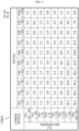
- FIG. 2 is a diagram referenced to explain an exemplary first charge reference map used in a charging procedure using a multi-stage constant-current charging protocol.
- the first charge reference map CRM1 is a table or function representing the correspondence between the charge rate for SOC and temperature of the battery 11, and can be referred to as a ⁇ charge rate map'.
- a total of M ⁇ N charge rates for the first to M th SOC sections (S#1 to S#M) and the first to N th temperature sections (T#1 to T#N) associated with the multi-stage constant-current charging protocol are recorded.
- M and N are natural numbers of 2 or more, respectively.
- the symbol C#m_n used in this specification represents the charge rate associated with the SOC section (S#m) and the temperature section (T#n). Additionally, the size (width) of the SOC section (S#m) is the difference between the start point and the end point of the SOC section (S#m). For example, in FIG. 2 , the start point of the SOC section (S#3) is 20%, the end point is 30%, and the size is 10%.
- the symbol ⁇ S#m used in this specification represents the size of the SOC section (S#m).
- the first to M th SOC section (S#1 to S#M) may be divided from the entire SOC range predetermined as the target of a charging procedure using a multi-stage constant-current charging protocol. That is, the start point of the first SOC section is the same as the start point of the entire SOC range, and the end point of the M th SOC section (S#M) is the same as the end point of the entire SOC range associated with the multi-stage constant-current charging protocol.
- the end point of the entire SOC range can be preset as the target SOC.
- the end point of the preceding section among the two adjacent sections may coincide with the start point of the following section. For example, the end point of the first SOC section coincides with the start point of the second SOC section.
- the charge rate associated with the temperature section (T#y) may be greater than or equal to the charge rate associated with the SOC section (T#x).
- the charge rate (C# 5_3 ) 1.2 C associated with the temperature section (T#3) is greater than the charge rate (C# 5_2 ) 1.0 C associated with the temperature section (T#2).
- the above-described example assumes that the first to eighth temperature sections (T#1 to T#8) are partitioned from a predetermined appropriate temperature range. Therefore, at temperatures lower than the start point of the temperature section (T#1) or higher than the end point of the temperature section (T#8), it should be understood that the change in charge rate according to temperature and SOC may be determined differently from FIG. 2 .
- the SOC estimation value of the battery 11 belongs to the SOC section (S#1) and the temperature detection value belongs to the temperature section (T#2) at the current time, constant-current charging using the charge rate (C# 1_2 ) of 1.0 C is performed.
- the temperature of the battery 11 at the end point of the SOC section (S#1) may actually belong to the temperature section (T#3) due to constant-current charging in the SOC section (S#1)
- the conventional method assumes that the temperature of the battery 11 remains in the temperature section (T#2) even in the SOC section (S#2) when predicting the remaining charging time.
- 1.0 C which is the charge rate (C# 2_2 ) associated with the temperature section (T#2) and the SOC section (S#2)
- 1.2 C which is the charge rate (C# 3_3 ) associated with the temperature section (T#3) and the SOC section (S#2)
- a difference between the time predicted to be required for charging from the start point to the end point of the SOC section (S#2) and the time actually required is generated as much as this difference.
- the present disclosure predicts the battery temperature in the next SOC section (e.g., S#2) during constant-current charging in a specific SOC section (e.g., S#1), reflects the predicted battery temperature in a subsequent SOC section (e.g., S#2) to predict which charge rate will be selected among the N charge rates, and then predicts the predicted charging time value in the SOC section (e.g. S#2) based on the predicted charge rate. Accordingly, compared to the conventional method described above, there is a technical effect in that the predicted charging time value for each SOC section from the current SOC section to the last SOC section can be obtained close to the actual value.
- S tA and T tA represent the SOC estimation value and the temperature detection value of the battery 11 at the time when the estimate operation of the total remaining time up to the target SOC is executed, that is, at the current time.
- the SOC estimation value (S tA ) is 35%
- the SOC estimation value (S tA ) belongs to the SOC section (S#4)
- the control unit 130 may determine the predicted charging time value ( ⁇ t#m), which represents the remaining time until the SOC of the battery 11 reaches the end point of the SOC section (S#m) from the current time by dividing the capacity corresponding to the SOC difference ( ⁇ S#m) by the charge rate (C#m_n).
- the maximum capacity of the battery 11 is 1000 mAh
- the SOC difference ( ⁇ S#m) is 5%
- the capacity corresponding to the SOC difference ( ⁇ S#m) is 20 mAh
- the maximum capacity of the battery 11 can be estimated using any one of various known methods or a combination of two or more of them.
- the control unit 130 may calculate the current maximum capacity of the battery 11 by dividing the accumulated current amount over the period from when the SOC of the battery 11 is at the first value to when the SOC of the battery 11 reaches the second value by the change amount of SOC (i.e., the difference between the first value and the second value).
- the control unit 130 may determine the maximum capacity of the battery 11 by multiplying the SOH (State Of Health) calculated through any one of various known methods or a combination of two or more of them by a predetermined design capacity (maximum capacity of a new battery).
- control unit 130 inputs the charge rate (C#m_n) and the predicted charging time value ( ⁇ t#m) into a pre-given thermal model to determine the predicted temperature change amount ( ⁇ T#m) of the battery 11 until reaching the end point of the SOC section (S#m) from the current point.
- the thermal model will be described separately later.
- the control unit 130 determines the predicted temperature value (T tB ) representing the temperature of the battery 11 at the end point of the SOC section (S#m) by adding the predicted temperature change amount ( ⁇ T#m) to the temperature detection value (T tA ). As described above, the end point of the SOC section (S#m) coincides with the start point of the SOC section (S#(m+1)), and thus the predicted temperature value (T tB ) also represents the temperature of the battery 11 when the SOC of the battery 11 reaches the start point of the SOC section (S#(m+1)) in the future.
- the operation of predicting the predicted charging time value for the SOC section (S#(m+1)) is common with the operation of predicting the predicted charging time value for the SOC section (S#m), except that the predicted temperature value (T tB ) is used instead of the temperature detection value (T tA ) when determining the charge rate in the first charge reference map CRM1.
- the control unit 130 repeats the above-described process for each SOC section until the predicted charging time value for the SOC section to which the target SOC belongs is determined, so that the predicted charging time value for each of the current SOC section (S#m) to the last SOC section (S#M) can be determined sequentially. Therefore, if all the predicted charging time values determined for the current SOC section (S#m) to the last SOC section (S#M) are added, the total remaining time until the constant-current charging from the current SOC section to the last SOC section (S#M) is completed can be determined.
- the inputs to the thermal model include a charge rate, a battery temperature value, and a predicted charging time value.
- the battery temperature value input to the thermal model may be a temperature detection value obtained using the battery temperature sensor 115 or the predicted temperature value described above.
- the output of the thermal model includes the predicted temperature change amount.
- ⁇ T ⁇ ⁇ I 2 ⁇ R + T ATM ⁇ T BAT ⁇ C H ⁇ ⁇ t
- T BAT is the battery temperature value
- ⁇ is the adjustment coefficient (predetermined)
- I is the charging current value corresponding to the charge rate
- R is the internal resistance value of the battery 11
- C H is the heat capacity of the battery 11 (predetermined)
- ⁇ t is the charging time
- T ATM is the outdoor air temperature value
- ⁇ is the heat exchange coefficient (predetermined).
- R and T ATM may be pre-given fixed values, respectively.
- R may be a variable value that can be adjusted by the control unit 130 according to the charging status of the battery 11.
- the outdoor air temperature detection value obtained using the outdoor air temperature sensor 117 can be used as the T ATM in the above formula.
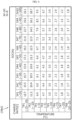
- FIG. 4 is a diagram referenced to explain an exemplary second charge reference map used in a charging procedure using a multi-stage constant-current charging protocol.
- the second charge reference map CRM2 repeated explanations of common content with the first charge reference map CRM1 will be omitted.
- the second charge reference map CRM2 is a table or function representing the correspondence of the internal resistance value to the SOC and temperature of the battery 11, and can be referred to as a ⁇ resistance value map'.
- a total of M ⁇ N internal resistance values for the first to M th SOC sections (S#1 to S#M) and first to N th temperature sections (T#1 to T#N) are recorded.
- the symbol R#m_n used in this specification represents the internal resistance value associated with the SOC section (S#m) and the temperature section (T#n).
- the second charge reference map CRM2 shown in FIG. 4 it can be seen that in a specific temperature section, as the SOC section is closer to the target SOC (e.g., 100%), the associated internal resistance value tends to gradually increase. For example, in the temperature section (T#1), the internal resistance value (R# 10_1 ) of 26.1 m ⁇ associated with the SOC section (S#10) is greater than the internal resistance value (R# 9_1 ) of 25.6 m ⁇ associated with the SOC section (S#9).
- the internal resistance value (R# 5_3 ) 6.4 m ⁇ associated with the temperature section (T#3) is smaller than the internal resistance value (R# 5_2 ) 11.3 m ⁇ associated with the temperature section (T#2).
- FIG. 4 should be understood as a simple example in explaining the present disclosure.
- the present disclosure can significantly improve the above-mentioned problems by using the internal resistance value obtained from the second charge reference map CRM2 as an input variable R for the thermal model exemplified above with reference to the formula, in calculating the predicted temperature change amount for each SOC section that must go through a charging procedure using a multi-stage constant-current charging protocol.
- FIG. 5 is a schematic diagram referenced to explain another example of the process of estimating the total remaining time, executed by the battery management system shown in FIG. 1 .
- the estimating process shown in FIG. 5 is different from the estimating process shown in FIG. 3 in that it additionally utilizes the internal resistance value obtained from the second charge reference map CRM2, so the explanation of contents in common with the estimating process described above with reference to FIG. 3 will be omitted as much as possible, and the explanation will be focused on the differences between the two estimating processes.
- S tA and T tA are the SOC estimation value and the temperature detection value of the battery 11 at the current time, respectively.
- the control unit 130 may obtain the charge rate (C#m_n) associated with the SOC section (S#m) and the temperature section (T#n) to which the SOC estimation value (StA) and the temperature detection value (TtA) belong from the first charge reference map CRM 1. Additionally, the control unit 130 may obtain the internal resistance value (R#m_n) associated with the SOC section (S#m) and the temperature section (T#n) from the second charge reference map CRM2.
- control unit 130 determines the predicted charging time value ( ⁇ t#m), and then determines the predicted temperature change amount ( ⁇ T#m) by additionally inputting the internal resistance value (R#m_n) along with the charge rate (C#m_n) and the predicted charging time value ( ⁇ t#m) into the thermal model.
- the control unit 130 determines the predicted temperature value (T tB ) by adding the predicted temperature change amount ( ⁇ T#m) to the temperature detection value (T tA ).
- the operation of predicting the predicted charging time value for the SOC section (S#(m+1)) following the current SOC section (S#m) is common with the operation of estimating the predicted charging time value for the SOC section (S#m) described above, except that the predicted temperature value (T tB ) at the end point of the SOC section (S#m) is used instead of the temperature detection value (T tA ) at the current time, in determining the charge rate in the first charge reference map CRM1.
- the current outdoor air temperature detection value at the current time obtained using the outdoor air temperature sensor 117 can be input as the T ATM of the thermal model.
- the outdoor air temperature usually does not change significantly during charging of the battery 11. Therefore, whenever the predicted temperature change amount for each SOC section where the charging procedure will proceed after the current time is determined, the outdoor air temperature value detected by the outdoor air temperature sensor 117 at the charging start point (or, the current time) can be identically input into the thermal model repeatedly.
- FIG. 6 is a flowchart exemplarily illustrating a battery charging time prediction method according to the first embodiment of the present disclosure.
- the method of FIG. 6 may be executed by the battery management system 100 at each set time while charging the battery 11 using a multi-stage constant-current charging protocol.
- only the first charge reference map CRM1 is used among the first charge reference map CRM1 and the second charge reference map CRM2.
- step S610 the control unit 130 determines the SOC estimation value of the battery 11 based on the voltage detection value, the current detection value, and the battery temperature detection value of the battery 11.
- the control unit 130 records the voltage detection value, the current detection value, the temperature detection value, and the SOC estimation value determined at each set time in the memory 140.
- the outdoor air temperature detection value (T ATM ) can be additionally determined.
- step S620 the control unit 130 determines the m th charge rate (C#m_n) associated with the m th SOC section (S#m, m is a natural number less than or equal to M) to which the SOC estimation value of the battery 11 belongs and the temperature section (T#n) to which the temperature detection value belongs, from the first charge reference map CRM1 associated with the multi-stage constant-current charging protocol.
- the m th SOC section (S#m) may be the current SOC section, and the m th charge rate may represent the size of the charging current used for constant-current charging in the m th SOC section (S#m).
- step S630 the control unit 130 determines the predicted charging time value in the m th SOC section (S#m) based on the m th charge rate (C#m_n) and the SOC difference ( ⁇ S#m) between the SOC estimation value and the end point of the m th SOC section (S#m).
- step S640 the control unit 130 determines the predicted temperature value at the end point of the m th SOC section (S#m), based on the m th charge rate (C#m_n) and the m th predicted charging time value in the m th SOC section (S#m). If the outdoor air temperature detection value (T ATM ) is determined in step S610, the predicted temperature value at the end point of the m th SOC section (S#m) may be determined further based on the outdoor air temperature detection value (T ATM ) in step S640.
- step S640 can be executed on the condition that m is less than M. If m is less than M, it means that there remains at least one SOC section following the m th SOC section (S#m) in which the charging procedure is currently in progress. That is, if the m th SOC section (S#m) is not the M th SOC section (S#M), step S640 may be performed.
- Step S640 may include step S642 and step S644.
- step S642 the control unit 130 determines the predicted temperature change amount ( ⁇ T#m) from the SOC estimation value to the end point of the m th SOC section (S#m), based on the m th charge rate (C#m_n) and the predicted charging time value in the m th SOC section (S#m), using a pre-given thermal model.
- step S644 the control unit 130 determines the predicted temperature value at the end point of the m th SOC section (S#m) by adding the predicted temperature change amount ( ⁇ T#m) from the SOC estimation value to the end point of the m th SOC section (S#m) to the temperature detection value.
- FIG. 7 is a flowchart exemplarily illustrating a battery charging time prediction method according to the second embodiment of the present disclosure.
- the method of FIG. 7 may be executed by the battery management system 100 at each set time while charging the battery 11 using a multi-stage constant-current charging protocol.
- both the first charge reference map CRM1 and the second charge reference map CRM2 are used.
- step S710 the control unit 130 determines the SOC estimation value of the battery 11 based on the voltage detection value, the current detection value, and the battery temperature detection value of the battery 11.
- Step S710 is substantially the same as step S610.
- step S720 the control unit 130 determines the m th charge rate (C#m_n) associated with the m th SOC section (S#m) to which the SOC estimation value of the battery 11 belongs and the temperature section (T#n) to which the temperature detection value belongs, from the first charge reference map CRM1 associated with the multi-stage constant-current charging protocol.
- Step S720 is substantially the same as step S620.
- step S722 the control unit 130 determines the m th internal resistance value (R#m_n) associated with the m th SOC section (S#m) and the temperature section (T#n) to which the temperature detection value belongs from the second charge reference map CRM2.
- step S730 the control unit 130 determines the predicted charging time value in the m th SOC section (S#m) based on the m th charge rate (C#m_n) and the SOC difference ( ⁇ S#m) between the SOC estimation value and the end point of the m th SOC section (S#m).
- Step S730 is substantially the same as step S630.
- step S740 the control unit 130 determines the predicted temperature value at the end point of the m th SOC section (S#m), based on the m th charge rate (C#m_n), the predicted charging time value in the m th SOC section (S#m), and the m th internal resistance value (R#m_n). If the outdoor air temperature detection value (T ATM ) is determined in step S710, the predicted temperature value at the end point of the m th SOC section (S#m) can be determined further based on the outdoor air temperature detection value (T ATM ) in step S740. Like step S640 described above, step S740 can be executed on the condition that I is less than M.
- Step S740 may include step S742 and step S744.
- step S742 the control unit 130 determines the predicted temperature change amount ( ⁇ T#m) from the SOC estimation value to the end point of the m th SOC section (S#m) using a pre-given thermal model, based on the m th charge rate (C#m_n), the predicted charging time value in the m th SOC section (S#m), and the m th internal resistance value (R#m_n).
- step S744 the control unit 130 determines the predicted temperature value at the end point of the m th SOC section (S#m) by adding the predicted temperature change amount ( ⁇ T#m) from the SOC estimation value to the end point of the m th SOC section (S#m) to the temperature detection value.
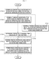
- FIG. 8 is a flowchart exemplarily illustrating a battery charging time prediction method according to the third embodiment of the present disclosure.
- the method of FIG. 8 may be performed subsequent to the method of FIG. 6 or the method of FIG. 7 , provided that m is less than M.
- m is less than M.
- only the first charge reference map CRM1 is used among the first charge reference map CRM1 and the second charge reference map CRM2.
- step S810 the control unit 130 sets the section index k equal to (m+1).
- step S820 the control unit 130 judges whether the predicted charging time value in the (k-1) th SOC section (S#(k-1)) and the predicted temperature value at the end point of the (k-1) th SOC section (S#(k-1)) are completely determined. If the value of step S820 is "Yes,” the process proceeds to step S830.
- step S830 the control unit 130 determines the k th charge rate associated with the k th SOC section (S#k) and the temperature section to which the predicted temperature value at the end point of the (k-1) th SOC section (S#(k-1)) belongs, from the first charge reference map CRM1.
- step S840 the control unit 130 determines the predicted charging time value in the k th SOC section (S#k) and the predicted temperature value at the end point of the k th SOC section (S#k) based on the k th charge rate and the size of the k th SOC section (S#k).
- Step S840 may include step S842 and step S844.
- step S842 the control unit 130 determines the predicted temperature change amount in the k th SOC section (S#k) using a pre-given thermal model, based on the k th charge rate and the predicted charging time value in the k th SOC section (S#k).
- step S844 the control unit 130 determines the predicted temperature value at the end point of the k th SOC section (S#k) by adding the predicted temperature change amount in the k th SOC section (S#k) to the predicted temperature value at the end point of the (k-1) th SOC section (S#(k-1)).
- step S850 the control unit 130 judges whether the section index k is equal to M.
- M can be said to be the identification number of the last SOC section (S#M) to which the target SOC belongs.
- the fact that the section index k is equal to M means that the determination of the predicted charging time value for the last SOC section (S#M) is completed. If the value of step S850 is "No", the process proceeds to step S852 to increase the section index k by 1, and then the process returns to step S820. That is, the above-described steps S820 to S852 can be repeated from when k is (m+1) until it increases to M.
- step S850 If the value of step S850 is "Yes,” the process proceeds to step S860.
- step S860 the control unit 130 determines the total remaining time until the charging procedure using the multi-stage constant-current charging protocol is terminated (i.e., until the SOC of the battery reaches the target SOC) by adding the m th to M th predicted charging time values.
- the m th to M th predicted charging time values correspond one-to-one to the m th to M th SOC sections (S#m to S#M).
- FIG. 9 is a flowchart exemplarily illustrating a battery charging time prediction method according to the fourth embodiment of the present disclosure.
- the method of FIG. 9 can be performed subsequent to the method of FIG. 6 or the method of FIG. 7 , provided that m, which is the section index of the SOC section (S#m) in which the charging procedure is currently in progress, is less than M.
- m which is the section index of the SOC section (S#m) in which the charging procedure is currently in progress, is less than M.
- S#m section index of the SOC section
- step S910 the control unit 130 sets the section index k equal to (m+1).
- Step S910 is substantially the same as step S810.
- step S920 the control unit 130 judges whether the predicted charging time value in the (k-1) th SOC section (S#(k-1)) and the predicted temperature value at the end point of the (k-1) th SOC section (S#(k-1)) are completely determined.
- Step S920 is substantially the same as step S820.
- step S930 the control unit 130 determines the k th charge rate associated with the k th SOC section (S#k) and the temperature section to which the predicted temperature value at the end point of the (k-1) th SOC section (S#(k-1)) belongs, from the first charge reference map CRM1.
- Step S930 is substantially the same as step S830.
- step S932 the control unit 130 determines the k th internal resistance value associated with the k th SOC section (S#k) and the temperature section to which the predicted temperature value at the end point of the (k-1) th SOC section (S#(k-1)) belongs, from the second charge reference map CRM2.
- step S940 the control unit 130 determines the predicted charging time value in the k th SOC section (S#k) and the predicted temperature value at the end point of the k th SOC section (S#k) based on the k th charge rate, the size of the k th SOC section (S#k), and the k th internal resistance value.
- Step S940 may include step S942 and step S944.
- step S942 the control unit 130 determines the predicted temperature change amount in the k th SOC section (S#k) using a pre-given thermal model, based on the k th charge rate, the predicted charging time value in the k th SOC section (S#k), and the k th internal resistance value.
- step S944 the control unit 130 determines the predicted temperature value at the end point of the k th SOC section (S#k) by adding the predicted temperature change amount in the k th SOC section (S#k) to the predicted temperature value at the end point of the (k-1) th SOC section (S#(k-1)).
- step S950 the control unit 130 judges whether the section index k is equal to M. If the value of step S950 is "No”, the process proceeds to step S952. If the value of step S950 is "No”, the process proceeds to step S952 to increase the section index k by 1, and then the process returns to step S920. If the value of step S950 is "Yes,” the process proceeds to step S960. Step S950 and step S952 are substantially the same as step S850 and step S852.
- step S960 the control unit 130 determines the total remaining time until the charging procedure using the multi-stage constant-current charging protocol is terminated by adding the m th to M th predicted charging time values. Step S960 is substantially the same as step S860.
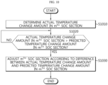
- FIG. 10 is a flowchart exemplarily illustrating a battery charging time prediction method according to the fifth embodiment of the present disclosure.
- the method of FIG. 10 can be executed to adjust the corresponding SOC section, provided that constant-current charging for each SOC section whose predicted charging time value has been determined by any one of the first to fourth embodiments described above with reference to FIGS. 6 to 9 is actually completed.
- step S1010 the control unit 130 determines the actual temperature change amount in the m th SOC section (S#m). If the m th SOC section (S#m) is a SOC section at the charging start point using the multi-stage constant-current charging protocol, the difference between the battery temperature detection value at the charging start point and the battery temperature detection value at the end point of the m th SOC section (S#m) can be determined as the actual temperature change amount in the m th SOC section (S#m).
- the difference between two battery temperature detection values at the start point and the end point of the m th SOC section (S#m) can be determined as the actual temperature change amount in the m th SOC section (S#m).
- step S1020 the control unit 130 determines whether the actual temperature change amount in the m th SOC section (S#m) is greater than the predicted temperature change amount in the m th SOC section (S#m). If the value of step S1020 is "Yes,” the process proceeds to step S1030.
- step S1030 the control unit 130 adjusts the m th SOC section (S#m) according to the difference between the actual temperature change amount and the predicted temperature change amount in the m th SOC section (S#m).
- control unit 130 may reduce the end point of the m th SOC section (S#m) by an adjustment value that has a predetermined positive correlation with respect to the difference. Accordingly, the size of the m th SOC section (S#m) is reduced by the adjustment value.
- the end point of the m th SOC section (S#m) is advanced by the adjustment value, which means that the start point of the (m+1) th SOC section (S#(m+1)) is also advanced by the adjustment value. Therefore, the size of the (m+1) th SOC section (S#(m+1)) is increased by the adjustment value.
- section index m is described, but it can also be commonly applied to the remaining section indexes smaller than or equal to M.
- the charging procedure for the SOC section in which an unexpected temperature rise occurs is terminated early, while the charging procedure for the SOC section following the corresponding SOC section is started early.
- the first charge reference map CRM 1 described above with reference to FIG. 3 if it is written so that a relatively small charge rate tends to be associated with a relatively high SOC section, the charge rate that causes an excessive temperature rise can be early switched to another lower charge rate, so that the charging procedure using the multi-stage constant-current charging protocol can be safely continued.
- the first charge reference map CRM1 is corrected to prevent the battery 11 from being overheated due to charging.
- control unit 130 may also correct the second charge reference map CRM2 to correspond to the correction of the first charge reference map CRM1. For example, when a specific SOC section of the first charge reference map CRM1 is adjusted, the specific SOC section of the second charge reference map CRM2 may also be adjusted in the same way.
- the embodiments of the present disclosure described above may not be implemented only through an apparatus and a method, but may be implemented through a program that realizes a function corresponding to the configuration of the embodiments of the present disclosure or a recording medium on which the program is recorded.
- the program or recording medium may be easily implemented by those skilled in the art from the above description of the embodiments.
Landscapes
- Engineering & Computer Science (AREA)
- Physics & Mathematics (AREA)
- General Physics & Mathematics (AREA)
- Power Engineering (AREA)
- General Chemical & Material Sciences (AREA)
- Chemical & Material Sciences (AREA)
- Chemical Kinetics & Catalysis (AREA)
- Electrochemistry (AREA)
- Manufacturing & Machinery (AREA)
- Life Sciences & Earth Sciences (AREA)
- Sustainable Development (AREA)
- Sustainable Energy (AREA)
- Transportation (AREA)
- Mechanical Engineering (AREA)
- Charge And Discharge Circuits For Batteries Or The Like (AREA)
- Secondary Cells (AREA)
- Electric Propulsion And Braking For Vehicles (AREA)
Applications Claiming Priority (3)
| Application Number | Priority Date | Filing Date | Title |
|---|---|---|---|
| KR20220116579 | 2022-09-15 | ||
| KR1020230054311A KR20240038565A (ko) | 2022-09-15 | 2023-04-25 | 배터리 관리 시스템, 배터리 팩, 전기 차량 및 배터리 충전 시간 예측 방법 |
| PCT/KR2023/009977 WO2024058387A1 (ko) | 2022-09-15 | 2023-07-12 | 배터리 관리 시스템, 배터리 팩, 전기 차량 및 배터리 충전 시간 예측 방법 |
Publications (2)
| Publication Number | Publication Date |
|---|---|
| EP4451503A1 true EP4451503A1 (de) | 2024-10-23 |
| EP4451503A4 EP4451503A4 (de) | 2025-08-20 |
Family
ID=90275490
Family Applications (1)
| Application Number | Title | Priority Date | Filing Date |
|---|---|---|---|
| EP23865690.4A Pending EP4451503A4 (de) | 2022-09-15 | 2023-07-12 | Batterieverwaltungssystem, batteriepack, elektrofahrzeug und batterieladezeitvorhersageverfahren |
Country Status (4)
| Country | Link |
|---|---|
| US (1) | US20260009858A1 (de) |
| EP (1) | EP4451503A4 (de) |
| JP (1) | JP2025501111A (de) |
| WO (1) | WO2024058387A1 (de) |
Families Citing this family (1)
| Publication number | Priority date | Publication date | Assignee | Title |
|---|---|---|---|---|
| CN118977601B (zh) * | 2024-08-01 | 2026-01-09 | 安徽锐能科技有限公司 | 电动汽车充电剩余时间估计方法、系统及存储介质 |
Family Cites Families (11)
| Publication number | Priority date | Publication date | Assignee | Title |
|---|---|---|---|---|
| JP5158872B2 (ja) * | 2008-06-12 | 2013-03-06 | 古河電気工業株式会社 | バッテリ状態検知方法、状態検知装置及びバッテリ電源システム |
| US20170055583A1 (en) | 2015-08-31 | 2017-03-02 | British American Tobacco (Investments) Limited | Apparatus for heating smokable material |
| KR102695516B1 (ko) * | 2016-11-18 | 2024-08-14 | 삼성전자주식회사 | 배터리 충전 방법, 배터리 충전 정보 생성 방법 및 배터리 충전 장치 |
| KR102676220B1 (ko) * | 2017-10-26 | 2024-06-19 | 삼성전자주식회사 | 배터리 상태를 측정하는 방법 및 장치 |
| JP2020036393A (ja) * | 2018-08-27 | 2020-03-05 | ヤマハ発動機株式会社 | 充電所要時間推定方法、充電所要時間推定装置および電動車両 |
| CN111257752B (zh) * | 2018-11-30 | 2021-02-26 | 宁德时代新能源科技股份有限公司 | 剩余充电时间估算方法、装置、系统和存储介质 |
| KR102392399B1 (ko) * | 2018-12-21 | 2022-04-28 | 주식회사 엘지에너지솔루션 | 이차 전지의 스텝 충전 제어 장치 및 방법 |
| US11150305B2 (en) * | 2019-09-04 | 2021-10-19 | Karma Automotive Llc | Method of estimating residual energy for a battery |
| KR102743393B1 (ko) * | 2019-09-06 | 2024-12-16 | 주식회사 엘지에너지솔루션 | 배터리 관리 장치, 배터리 관리 방법, 배터리 팩 및 전기 차량 |
| CN110909443A (zh) * | 2019-10-12 | 2020-03-24 | 北京航空航天大学 | 一种高精度电池组充电剩余时间估算方法及系统 |
| CN116745928A (zh) | 2021-10-13 | 2023-09-12 | 宁德时代新能源科技股份有限公司 | 电极组件、二次电池、电池模块、电池包及用电装置 |
-
2023
- 2023-07-12 JP JP2024537949A patent/JP2025501111A/ja active Pending
- 2023-07-12 EP EP23865690.4A patent/EP4451503A4/de active Pending
- 2023-07-12 WO PCT/KR2023/009977 patent/WO2024058387A1/ko not_active Ceased
- 2023-07-12 US US18/707,935 patent/US20260009858A1/en active Pending
Also Published As
| Publication number | Publication date |
|---|---|
| EP4451503A4 (de) | 2025-08-20 |
| WO2024058387A1 (ko) | 2024-03-21 |
| US20260009858A1 (en) | 2026-01-08 |
| JP2025501111A (ja) | 2025-01-17 |
Similar Documents
| Publication | Publication Date | Title |
|---|---|---|
| US12370922B2 (en) | Battery management apparatus, battery management method, battery pack, and electric vehicle | |
| EP4429067A1 (de) | Batterieverwaltungssystem, batteriepack, elektrofahrzeug und batterieladezeitvorhersageverfahren | |
| CN116324449B (zh) | 电池诊断设备、电池组、电动车辆和电池诊断方法 | |
| EP3929606B1 (de) | Batterieverwaltungssystem, batteriepack, elektrofahrzeug und batterieverwaltungsverfahren | |
| CN114402211B (zh) | 电池管理系统、电池管理方法、电池组和电动车辆 | |
| US20260056257A1 (en) | Battery Management System, Battery Management Method, Battery Pack, and Electric Vehicle | |
| CN115943316B (zh) | 电池诊断设备、电池诊断方法、电池组和电动车辆 | |
| EP4024067B1 (de) | Batterieverwaltungssystem, batteriepack, elektrofahrzeug und batterieverwaltungsverfahren | |
| JP2021524138A (ja) | バッテリー管理装置、バッテリー管理方法及びバッテリーパック | |
| KR20240037823A (ko) | 배터리 관리 시스템, 배터리 팩, 전기 차량 및 배터리 충전 시간 예측 방법 | |
| EP4571339A1 (de) | Batterieverwaltungssystem, batteriepack, elektrofahrzeug und batterieverwaltungsverfahren | |
| US20260112913A1 (en) | Charging Control Apparatus and Charging Control Method | |
| JP7062870B2 (ja) | バッテリー管理装置、バッテリー管理方法及びバッテリーパック | |
| CN118238673A (zh) | 电池管理系统、电池管理方法、电池组及电动车辆 | |
| EP4451503A1 (de) | Batterieverwaltungssystem, batteriepack, elektrofahrzeug und batterieladezeitvorhersageverfahren | |
| KR20240038565A (ko) | 배터리 관리 시스템, 배터리 팩, 전기 차량 및 배터리 충전 시간 예측 방법 | |
| CN118120126A (zh) | 电池管理系统、电池组、电动车辆和电池充电时间预测方法 | |
| JPH08339834A (ja) | 蓄電池の劣化度判定方法、及び劣化度判定装置 | |
| EP4575539A1 (de) | Batterieverwaltungssystem, batteriepack, elektrofahrzeug und batterieverwaltungsverfahren | |
| CN118216057A (zh) | 电池管理系统、电池组、电动车辆及电池充电时间预测方法 | |
| EP4617693A1 (de) | Vorrichtung und verfahren zur erfassung von batterieverschlechterungsindikatorinformationen, batteriepack und elektrofahrzeug | |
| CN118843800A (zh) | 电池管理系统、电池组、电动车辆以及电池管理方法 | |
| EP4729970A1 (de) | Batteriediagnosevorrichtung und batteriediagnoseverfahren | |
| KR20240168222A (ko) | 충전 제어 장치 및 충전 제어 방법 |
Legal Events
| Date | Code | Title | Description |
|---|---|---|---|
| STAA | Information on the status of an ep patent application or granted ep patent |
Free format text: STATUS: THE INTERNATIONAL PUBLICATION HAS BEEN MADE |
|
| PUAI | Public reference made under article 153(3) epc to a published international application that has entered the european phase |
Free format text: ORIGINAL CODE: 0009012 |
|
| STAA | Information on the status of an ep patent application or granted ep patent |
Free format text: STATUS: REQUEST FOR EXAMINATION WAS MADE |
|
| 17P | Request for examination filed |
Effective date: 20240719 |
|
| AK | Designated contracting states |
Kind code of ref document: A1 Designated state(s): AL AT BE BG CH CY CZ DE DK EE ES FI FR GB GR HR HU IE IS IT LI LT LU LV MC ME MK MT NL NO PL PT RO RS SE SI SK SM TR |
|
| REG | Reference to a national code |
Ref country code: DE Ref legal event code: R079 Free format text: PREVIOUS MAIN CLASS: H02J0007000000 Ipc: H01M0010440000 |
|
| A4 | Supplementary search report drawn up and despatched |
Effective date: 20250718 |
|
| RIC1 | Information provided on ipc code assigned before grant |
Ipc: H01M 10/44 20060101AFI20250714BHEP Ipc: H01M 10/48 20060101ALI20250714BHEP Ipc: H02J 7/00 20060101ALI20250714BHEP Ipc: G01R 31/382 20190101ALI20250714BHEP Ipc: G01R 31/385 20190101ALI20250714BHEP Ipc: G01R 31/396 20190101ALI20250714BHEP Ipc: G01R 31/389 20190101ALI20250714BHEP Ipc: B60L 58/12 20190101ALI20250714BHEP Ipc: B60L 3/00 20190101ALI20250714BHEP Ipc: G01R 31/36 20200101ALI20250714BHEP |
|
| DAV | Request for validation of the european patent (deleted) | ||
| DAX | Request for extension of the european patent (deleted) | ||
| RIC1 | Information provided on ipc code assigned before grant |
Ipc: H01M 10/44 20060101AFI20251218BHEP Ipc: H01M 10/48 20060101ALI20251218BHEP Ipc: H02J 7/00 20060101ALI20251218BHEP Ipc: G01R 31/382 20190101ALI20251218BHEP Ipc: G01R 31/385 20190101ALI20251218BHEP Ipc: G01R 31/396 20190101ALI20251218BHEP Ipc: G01R 31/389 20190101ALI20251218BHEP Ipc: B60L 58/12 20190101ALI20251218BHEP Ipc: B60L 3/00 20190101ALI20251218BHEP Ipc: G01R 31/36 20200101ALI20251218BHEP |
|
| GRAP | Despatch of communication of intention to grant a patent |
Free format text: ORIGINAL CODE: EPIDOSNIGR1 |
|
| STAA | Information on the status of an ep patent application or granted ep patent |
Free format text: STATUS: GRANT OF PATENT IS INTENDED |
|
| INTG | Intention to grant announced |
Effective date: 20260305 |