EP4451348A2 - Methode zur stromerzeugung mit einem modularen photovoltaiksystem - Google Patents
Methode zur stromerzeugung mit einem modularen photovoltaiksystem Download PDFInfo
- Publication number
- EP4451348A2 EP4451348A2 EP24199025.8A EP24199025A EP4451348A2 EP 4451348 A2 EP4451348 A2 EP 4451348A2 EP 24199025 A EP24199025 A EP 24199025A EP 4451348 A2 EP4451348 A2 EP 4451348A2
- Authority
- EP
- European Patent Office
- Prior art keywords
- light
- edge
- photovoltaic
- lit
- panel
- Prior art date
- Legal status (The legal status is an assumption and is not a legal conclusion. Google has not performed a legal analysis and makes no representation as to the accuracy of the status listed.)
- Pending
Links
Images


Classifications
-
- H—ELECTRICITY
- H10—SEMICONDUCTOR DEVICES; ELECTRIC SOLID-STATE DEVICES NOT OTHERWISE PROVIDED FOR
- H10F—INORGANIC SEMICONDUCTOR DEVICES SENSITIVE TO INFRARED RADIATION, LIGHT, ELECTROMAGNETIC RADIATION OF SHORTER WAVELENGTH OR CORPUSCULAR RADIATION
- H10F77/00—Constructional details of devices covered by this subclass
- H10F77/40—Optical elements or arrangements
- H10F77/42—Optical elements or arrangements directly associated or integrated with photovoltaic cells, e.g. light-reflecting means or light-concentrating means
-
- H—ELECTRICITY
- H10—SEMICONDUCTOR DEVICES; ELECTRIC SOLID-STATE DEVICES NOT OTHERWISE PROVIDED FOR
- H10F—INORGANIC SEMICONDUCTOR DEVICES SENSITIVE TO INFRARED RADIATION, LIGHT, ELECTROMAGNETIC RADIATION OF SHORTER WAVELENGTH OR CORPUSCULAR RADIATION
- H10F77/00—Constructional details of devices covered by this subclass
- H10F77/93—Interconnections
-
- H—ELECTRICITY
- H10—SEMICONDUCTOR DEVICES; ELECTRIC SOLID-STATE DEVICES NOT OTHERWISE PROVIDED FOR
- H10F—INORGANIC SEMICONDUCTOR DEVICES SENSITIVE TO INFRARED RADIATION, LIGHT, ELECTROMAGNETIC RADIATION OF SHORTER WAVELENGTH OR CORPUSCULAR RADIATION
- H10F19/00—Integrated devices, or assemblies of multiple devices, comprising at least one photovoltaic cell covered by group H10F10/00, e.g. photovoltaic modules
- H10F19/10—Integrated devices, or assemblies of multiple devices, comprising at least one photovoltaic cell covered by group H10F10/00, e.g. photovoltaic modules comprising photovoltaic cells in arrays in a single semiconductor substrate, the photovoltaic cells having vertical junctions or V-groove junctions
-
- H—ELECTRICITY
- H10—SEMICONDUCTOR DEVICES; ELECTRIC SOLID-STATE DEVICES NOT OTHERWISE PROVIDED FOR
- H10F—INORGANIC SEMICONDUCTOR DEVICES SENSITIVE TO INFRARED RADIATION, LIGHT, ELECTROMAGNETIC RADIATION OF SHORTER WAVELENGTH OR CORPUSCULAR RADIATION
- H10F19/00—Integrated devices, or assemblies of multiple devices, comprising at least one photovoltaic cell covered by group H10F10/00, e.g. photovoltaic modules
- H10F19/30—Integrated devices, or assemblies of multiple devices, comprising at least one photovoltaic cell covered by group H10F10/00, e.g. photovoltaic modules comprising thin-film photovoltaic cells
-
- H—ELECTRICITY
- H10—SEMICONDUCTOR DEVICES; ELECTRIC SOLID-STATE DEVICES NOT OTHERWISE PROVIDED FOR
- H10F—INORGANIC SEMICONDUCTOR DEVICES SENSITIVE TO INFRARED RADIATION, LIGHT, ELECTROMAGNETIC RADIATION OF SHORTER WAVELENGTH OR CORPUSCULAR RADIATION
- H10F19/00—Integrated devices, or assemblies of multiple devices, comprising at least one photovoltaic cell covered by group H10F10/00, e.g. photovoltaic modules
- H10F19/80—Encapsulations or containers for integrated devices, or assemblies of multiple devices, having photovoltaic cells
-
- H—ELECTRICITY
- H10—SEMICONDUCTOR DEVICES; ELECTRIC SOLID-STATE DEVICES NOT OTHERWISE PROVIDED FOR
- H10F—INORGANIC SEMICONDUCTOR DEVICES SENSITIVE TO INFRARED RADIATION, LIGHT, ELECTROMAGNETIC RADIATION OF SHORTER WAVELENGTH OR CORPUSCULAR RADIATION
- H10F77/00—Constructional details of devices covered by this subclass
- H10F77/40—Optical elements or arrangements
- H10F77/42—Optical elements or arrangements directly associated or integrated with photovoltaic cells, e.g. light-reflecting means or light-concentrating means
- H10F77/484—Refractive light-concentrating means, e.g. lenses
-
- H—ELECTRICITY
- H10—SEMICONDUCTOR DEVICES; ELECTRIC SOLID-STATE DEVICES NOT OTHERWISE PROVIDED FOR
- H10F—INORGANIC SEMICONDUCTOR DEVICES SENSITIVE TO INFRARED RADIATION, LIGHT, ELECTROMAGNETIC RADIATION OF SHORTER WAVELENGTH OR CORPUSCULAR RADIATION
- H10F77/00—Constructional details of devices covered by this subclass
- H10F77/40—Optical elements or arrangements
- H10F77/42—Optical elements or arrangements directly associated or integrated with photovoltaic cells, e.g. light-reflecting means or light-concentrating means
- H10F77/488—Reflecting light-concentrating means, e.g. parabolic mirrors or concentrators using total internal reflection
-
- Y—GENERAL TAGGING OF NEW TECHNOLOGICAL DEVELOPMENTS; GENERAL TAGGING OF CROSS-SECTIONAL TECHNOLOGIES SPANNING OVER SEVERAL SECTIONS OF THE IPC; TECHNICAL SUBJECTS COVERED BY FORMER USPC CROSS-REFERENCE ART COLLECTIONS [XRACs] AND DIGESTS
- Y02—TECHNOLOGIES OR APPLICATIONS FOR MITIGATION OR ADAPTATION AGAINST CLIMATE CHANGE
- Y02B—CLIMATE CHANGE MITIGATION TECHNOLOGIES RELATED TO BUILDINGS, e.g. HOUSING, HOUSE APPLIANCES OR RELATED END-USER APPLICATIONS
- Y02B10/00—Integration of renewable energy sources in buildings
- Y02B10/10—Photovoltaic [PV]
-
- Y—GENERAL TAGGING OF NEW TECHNOLOGICAL DEVELOPMENTS; GENERAL TAGGING OF CROSS-SECTIONAL TECHNOLOGIES SPANNING OVER SEVERAL SECTIONS OF THE IPC; TECHNICAL SUBJECTS COVERED BY FORMER USPC CROSS-REFERENCE ART COLLECTIONS [XRACs] AND DIGESTS
- Y02—TECHNOLOGIES OR APPLICATIONS FOR MITIGATION OR ADAPTATION AGAINST CLIMATE CHANGE
- Y02E—REDUCTION OF GREENHOUSE GAS [GHG] EMISSIONS, RELATED TO ENERGY GENERATION, TRANSMISSION OR DISTRIBUTION
- Y02E10/00—Energy generation through renewable energy sources
- Y02E10/50—Photovoltaic [PV] energy
- Y02E10/52—PV systems with concentrators
Definitions
- the present disclosure relates generally to a photovoltaic system for generating electricity using solar energy.
- the present disclosure relates to a modular photovoltaic system with a compact edge-lit photovoltaic array which is illuminated by a separate solar collector.
- Solar energy is an increasingly important form of renewable energy.
- traditional solar panel arrays must be exposed to direct sunlight, and therefore require significant amounts of space in order to ensure that the solar panels are unobstructed.
- Solar panel arrays for powering houses may occupy tens or even hundreds of square feet worth of rooftop space, while solar power plants may require many square miles of ground space.
- traditional solar panels remain exposed to the elements as well as environmental debris, and their effectiveness may rapidly degrade without labor-intensive cleaning and maintenance. Even though solar cell technology continues to improve, the maintenance and space requirements for the proper operation of traditional solar panel arrays pose a major barrier against further adoption of solar energy.
- improved solar panels can be found within the prior art. These devices seek to alleviate the cost of operating solar panel arrays by improving the efficiency of the solar panels, thus increasing the amount of electricity which can be generated for a given unit of surface area.
- these improved solar panels still require direct exposure to sunlight, and therefore fail to address the space requirements and maintenance overhead inherent in the operation of traditional solar panel arrays.
- the efficiency of new solar panel technology continues to increase, the investment value of existing solar panel arrays will decay, as the operators of the now obsolescent solar panels must choose between upgrading their solar panel arrays at great cost, or making inefficient use of ground and surface area by continuing to operate older, less effective solar panels.
- An aspect of an example embodiment in the present disclosure is to provide a photovoltaic system capable of generating electric current using solar without directly exposing its photovoltaic components to the sun.
- the present disclosure provides a modular photovoltaic system comprising an edge-lit photovoltaic array, and a light tracking solar collector adapted to collect light rays from a solar light source and transport the collected light rays to the edge lit photovoltaic array using a light transport conduit.
- the light-tracking solar collector employs a light focusing means, such as a lens, to collect and focus the light rays without requiring the edge-lit photovoltaic array to be directly exposed to the solar light source.
- the present disclosure provides an edge-lit photovoltaic array comprising a plurality of stacked edge-lit photovoltaic panels each having a transparent diffusing pane positioned between two backing panels with photovoltaic surfaces, and a lateral light distributor which is in perpendicular contact with each edge-lit photovoltaic panel. Light rays from the solar collector are transferred to the lateral light distributor via the transport conduit, while the lateral light distributor illuminates the transparent diffusing pane and the photovoltaic surfaces of each edge-lit photovoltaic panel.
- the present disclosure provides a light-tracking solar collector having a light sensor for determining the position of the solar light source, and a motorized tracking mechanism adapted to rotate and/or elevate the solar collector in order to orient the light focusing means towards the solar light source.
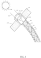
- FIG 1 illustrates a modular photovoltaic system 10 adapted to generate electrical current using solar energy, comprising an edge-lit photovoltaic array 12, a light-tracking solar collector 50, and a transport conduit 54.
- the transport conduit 54 contains a light transport medium 60, such as a fiber optic cable, which is adapted to transport light by internal reflection, allowing the light-tracking solar collector 50 to collect light rays 102 emitted from a solar light source 100, such as the sun, which are then delivered to the edge-lit photovoltaic array 12 via the transport conduit 54.
- a light transport medium 60 such as a fiber optic cable
- the edge-lit photovoltaic array 12 is formed using one or more edge-lit photovoltaic panels 14.
- Each edge-lit photovoltaic panel 14 has a transparent central pane 16 positioned between, and in contact with, a pair of backing panels 20.
- Each transparent central pane 16 is formed of a transparent material such as glass, polycarbonate, or other similar material capable of transmitting light.
- Each transparent central pane 16 has a light receiving edge 16T which is transparent and is adapted to receive light, and a pair of opposing light emitting faces 16F.
- the light emitting faces 16F each have an irregular surface which is adapted to scatter light, and the irregular surface may be produced by etching, scoring, or a similar process.
- Each backing panel 20 has an inward-facing photovoltaic surface 20V in contact with one of the light emitting faces 16F, comprising one or more solar cells which are adapted to convert energy from photons within the light rays 102 into electrical current.
- An output line 120 may be employed to carry the electrical current produced by the edge-lit photovoltaic array 12 to be consumed or stored as necessary.
- each edge-lit photovoltaic panel 14 is rectangular in shape, and has a panel top edge 18T which exposes the light receiving edge 16T of the transparent diffusing pane 16, a pair of panel side edges 18S, and a panel bottom edge 18B.
- the transparent diffusing pane 16 further has a pair of transparent side edges 16S, and a transparent bottom edge 16B.
- the edge-lit photovoltaic panels 14 are stacked together to give the edge-lit photovoltaic array 12 a substantially block-like shape, while the panel top edges 18T of each edge-lit photovoltaic panel 14 are substantially aligned to form a rectangular top face 12T.
- the transparent side edges 16S, the transparent bottom edge 16B, and the light receiving edge 16T are coextensive with the panel side edges 18S, the panel bottom edge 18B, and the panel top edge 18T respectively.
- the panel side edges 18S align to collectively form a pair of rectangular side faces 12S, while the panel bottom edges 18B align to collectively form a rectangular bottom face 12B.
- the edge-lit photovoltaic array 12 further has a plurality of reflective side panels 22 and a reflective bottom panel 24 positioned over the rectangular side faces 12S and the rectangular bottom face 12B respectively, which cover the panel side edges 18S and the panel bottom edge 18B of each edge-lit photovoltaic panel 14 within the edge-lit photovoltaic array 12.
- the reflective side and bottom panels 22, 24 are adapted to trap light within the edge-lit photovoltaic array 12 and facilitate internal reflection by reflecting the light rays 102 which travel through the transparent side edges 16S or the transparent bottom edge 16B transparent diffusing pane 16.
- the reflective side and bottom panels 22, 24 may incorporate mylar or dielectric mirrors, as well as any other suitable reflective material.
- the edge-lit photovoltaic array 12 may have a fully sealed exterior to protect the edge-lit photovoltaic panels from being damaged or adversely impacted by the elements or by environmental debris.
- the modular photovoltaic system 10 further has a lateral light distributor 30 which is adapted to receive the light rays 102 collected by the light-tracking solar collector 50, and distribute the light rays 102 to each edge-lit photovoltaic panel 14 within the edge- lit photovoltaic array 12.
- the lateral light distributor 30 comprises a light distributing medium 30M which has a collecting point 32 which is connected to the transport conduit 54, and a distributing surface 34 which is adapted to contact the light receiving edge 16T of each edge-lit photovoltaic panel 14 within the edge-lit photovoltaic array 12, forming a boundary through which the light rays 102 may be propagated.
- the distributing surface 34 is substantially flat, and is positioned perpendicular to, and in contact with, the aligned panel top edges 16T of each edge-lit photovoltaic panel 14.
- the light distributing medium 30M is transparent and capable of transmitting light. Similarly to the transparent diffusing pane 16 of the edge-lit photovoltaic panel 14, the light distributing medium 30M may be formed using glass, polycarbonate, or other suitable transparent material. The light rays 102 entering the lateral light-distributor 30 are transported laterally across the distributing surface 34 to each edge-lit photovoltaic panel 14, via contact between the light receiving edges 16T and the distributing surface 34.
- the light distributing medium 30M is further covered with an inwardly oriented reflective layer 36, which traps and reflects the light rays 102 within the lateral light distributor 30.
- the reflective layer 36 may be composed of mylar or dielectric mirrors or another suitable reflective material.
- the reflective layer 36 covers substantially the entirety of the lateral light distributor 30 with the exception of the distributing surface 34.
- the distributing surface 34 has sufficient area to completely cover the light receiving edge 16T of each edge-lit photovoltaic panel 14, and may be rectangular to conform to the top face 12T of the edge-lit photovoltaic array 12.
- the light rays 102 travel through the boundary between the distributing surface 34 of the lateral light distributor 30 and the light receiving edges 16T of each edge-lit photovoltaic panel 14, and are transmitted through the transparent diffusing pane 16 before being scattered through the light emitting faces 16F to illuminate the photovoltaic surfaces 20 V of the backing panels 20.
- the solar cells within the photovoltaic surfaces 20V are exposed to the light rays 102, and are able to generate electrical current without being directly exposed to the solar light source 100.
- edge-lit photovoltaic panels 14 may be employed, thereby greatly increasing the combined area of the photovoltaic surfaces 20V that can be deployed at a given space, when compared to conventional solar panels which must be directly exposed to sunlight.
- each edge-lit photovoltaic panel 14 may have an area of one square foot and a thickness of 0.8 inches.
- the combined photovoltaic surfaces 20V of each edge-lit photovoltaic panel 14 would have an area of two square feet.
- An edge-lit photovoltaic array 12 comprising fifteen individual edge-lit photovoltaic panels 14 would have a volume of one cubic foot and have thirty square feet of photovoltaic surfaces 20V, while occupying only a single square foot if placed on a flat surface.
- each edge-lit photovoltaic panel 14 may have a variable area and thickness.
- the lateral light distributor 30 may have a tapering configuration 30C in the form of a pyramid or cone with a base corresponding to the distributing surface 34, and an upper tip 30T positioned above the distributing surface 34.
- the collecting point 32 is located at the upper tip 30T, and the light rays 102 travel downwardly from the upper tip 30T through the light distributing medium 30 towards the distributing surface 34.
- the pyramidal or cone-like shape of the tapering configuration 30C causes any reflected light rays 102 traveling within the light distributing medium 30M to be directed towards the distributing surface 34.
- the lateral light distributor 30 may be in the form of a substantially flat panel or block.
- the ability of the edge-lit photovoltaic array 12 to generate electrical current is dependent on the amount of light from the solar light source 100, which is collected by the light-tracking solar collector 50.
- the light-tracking solar collector 50 has a collector head 50H with one or more light focusing means 52 positioned therein.
- the light focusing means 52 comprises a lens 52F.
- the transport conduit 54 joins the collector head 50H to the collecting point 32 of the lateral light-distributor 30.
- the light transport medium 60 has a first end 60A which is connected to the collector head 50H, and a second end 60B which is operably connected to the lateral light distributor 30 via the collecting point 32.
- the collector head 50H is positioned facing the solar light source 100, allowing the light rays 102 to be collected by the light focusing means 52.
- the collected light rays 102 are directed towards the first end 60A of the light transport medium 60 and are transported to the collecting point 32 and the lateral light distributor 30 via the second end 60B.
- the light transport medium 60 comprises a fiber optic cable 62 and reflective cladding 64 to effect internal reflection of the light rays 102 through the light transport medium 60.
- other light focusing means 52 may be employed in place of, or in combination with a lens 52F.
- the light rays 102 may be gathered and focused upon the first end 60A of the light transport medium 60 using reflective mirrors, mirror dishes, or other suitable means as will be apparent to a person of ordinary skill in the art in the field of the invention.
- the light-tracking solar collector 50 is adapted to swivel and/or rotate to allow the collector head 50H to remain oriented towards the solar light source 100, thereby maximizing the amount of light to which the collector head 50H is exposed as the sun moves across the sky.
- the light-tracking solar collector 50 may therefore have a tracking mechanism 66 adapted to rotate and/or elevate the collector head 50 H in response to the movement of the sun.
- the tracking mechanism 66 may be implemented using a motor or similar apparatus.
- the transport conduit 54 is correspondingly flexible to allow the movement of the collector head 50 H and/or the light-tracking solar collector 50.
- the tracking mechanism 66 may be controlled using one or more light sensors 68 which determine the position of the solar light source 100.
- the light-tracking solar collector 50 may have multiple light focusing means 52.
- the collector head 50H may have three light focusing means 52, and three transport conduits 54. All three transport conduits 54 are attached to the collecting point 32 of the lateral light distributor 30, thereby increasing the amount of light which is collected and delivered to the edge-lit photovoltaic array 12.
- the modular photovoltaic system 10 may employ multiple edge-lit photovoltaic arrays 12, each with one or more light-tracking solar collectors 50.
- the transport conduit 54 may be any length, allowing the edge-lit photovoltaic array 12 to be positioned separately from the light-tracking solar collector 50, as allowed by the length of the transport conduit 54.
- the modular photovoltaic system 10 may be employed within a building 140 or other structure which has an interior space 1401.
- the light-tracking solar collector 50 may be placed on the exterior 140E of the building 140 so that it can be exposed to the solar light source 100, while the edge-lit photovoltaic array 12 is positioned within the interior space 1401, thus preventing the need to occupy the exterior 140E with solar panels and further protecting the edge-lit photovoltaic array 12 from exposure to the elements.
- the modular photovoltaic system 10 allows the various components of the system to be replaced in a modular fashion, thus allowing the modular photovoltaic system 10 to be repaired or upgraded.
- each edge-lit photovoltaic panel 14 may be removed from the edge-lit photovoltaic array 12 to be replaced.
- the edge-lit photovoltaic array 12 may be detached from the lateral light distributor 30 and/or the transport conduit 54.
- the edge-lit photovoltaic panels 14 may instead have backing panels 20 with double-sided photovoltaic surfaces 20V.
- the backing panels 20 with double-sided photovoltaic surfaces 20V may therefore be positioned between two transparent diffusing panes 16, thus ensuring that each photovoltaic surface 20V is in contact with one of the light emitting faces 16F.
- any components or materials can be formed from a same, structurally continuous piece or separately fabricated and connected.
- spatially relative terms such as “beneath,” “below,” “lower,” “above,” “upper” and the like, are used herein for ease of description to describe one element or feature's relationship to another element(s) or feature(s) as illustrated in the figures. It is understood that the spatially relative terms are intended to encompass different orientations of the device in use or operation in addition to the orientation depicted in the figures. For example, if the device in the figures is turned over, elements described as “below” or “beneath” other elements or features would then be oriented “above” the other elements or features. Thus, the example term “below” can encompass both an orientation of above and below. The device can be otherwise oriented (rotated 90 degrees or at other orientations) and the spatially relative descriptors used herein interpreted accordingly.
- Example embodiments are described herein with reference to cross section illustrations that are schematic illustrations of idealized embodiments. As such, variations from the shapes of the illustrations as a result, for example, of manufacturing techniques and/or tolerances, are to be expected. Thus, example embodiments described herein should not be construed as limited to the particular shapes of regions as illustrated herein, but are to include deviations in shapes that result, for example, from manufacturing. For example, a region illustrated or described as flat may, typically, have rough and/or nonlinear features. Moreover, sharp angles that are illustrated may be rounded. Thus, the regions illustrated in the figures are schematic in nature and their shapes are not intended to illustrate the precise shape of a region and are not intended to limit the scope of the present claims.
Landscapes
- Photovoltaic Devices (AREA)
- Life Sciences & Earth Sciences (AREA)
- Engineering & Computer Science (AREA)
- Sustainable Development (AREA)
- Sustainable Energy (AREA)
Applications Claiming Priority (3)
| Application Number | Priority Date | Filing Date | Title |
|---|---|---|---|
| US16/507,369 US10930800B2 (en) | 2019-07-10 | 2019-07-10 | Modular photovoltaic system |
| EP20837409.0A EP3984071B1 (de) | 2019-07-10 | 2020-06-18 | Methode zur stromerzeugung mit einem modularen photovoltaiksystem |
| PCT/US2020/038430 WO2021007010A1 (en) | 2019-07-10 | 2020-06-18 | Modular photovoltaic system |
Related Parent Applications (2)
| Application Number | Title | Priority Date | Filing Date |
|---|---|---|---|
| EP20837409.0A Division EP3984071B1 (de) | 2019-07-10 | 2020-06-18 | Methode zur stromerzeugung mit einem modularen photovoltaiksystem |
| EP20837409.0A Division-Into EP3984071B1 (de) | 2019-07-10 | 2020-06-18 | Methode zur stromerzeugung mit einem modularen photovoltaiksystem |
Publications (2)
| Publication Number | Publication Date |
|---|---|
| EP4451348A2 true EP4451348A2 (de) | 2024-10-23 |
| EP4451348A3 EP4451348A3 (de) | 2025-01-08 |
Family
ID=74102378
Family Applications (2)
| Application Number | Title | Priority Date | Filing Date |
|---|---|---|---|
| EP20837409.0A Active EP3984071B1 (de) | 2019-07-10 | 2020-06-18 | Methode zur stromerzeugung mit einem modularen photovoltaiksystem |
| EP24199025.8A Pending EP4451348A3 (de) | 2019-07-10 | 2020-06-18 | Modulares fotovoltaisches system |
Family Applications Before (1)
| Application Number | Title | Priority Date | Filing Date |
|---|---|---|---|
| EP20837409.0A Active EP3984071B1 (de) | 2019-07-10 | 2020-06-18 | Methode zur stromerzeugung mit einem modularen photovoltaiksystem |
Country Status (4)
| Country | Link |
|---|---|
| US (3) | US10930800B2 (de) |
| EP (2) | EP3984071B1 (de) |
| ES (1) | ES2999100T3 (de) |
| WO (1) | WO2021007010A1 (de) |
Families Citing this family (3)
| Publication number | Priority date | Publication date | Assignee | Title |
|---|---|---|---|---|
| US11929707B2 (en) * | 2019-10-13 | 2024-03-12 | Nasir Sharaf | System for maximizing solar insolation utilization in power generation |
| CN115720078A (zh) * | 2022-11-17 | 2023-02-28 | 阳光新能源开发股份有限公司 | 一种光伏发电站 |
| WO2024175899A1 (en) * | 2023-02-20 | 2024-08-29 | Mohammed Zulfiquar | Solar energy apparatus |
Family Cites Families (18)
| Publication number | Priority date | Publication date | Assignee | Title |
|---|---|---|---|---|
| DE3005914A1 (de) | 1980-02-16 | 1981-09-10 | Werner H. Prof. Dr.-Ing. 7065 Winterbach Bloss | Solarzellenanordnung |
| US4411490A (en) * | 1980-08-18 | 1983-10-25 | Maurice Daniel | Apparatus for collecting, distributing and utilizing solar radiation |
| US5575860A (en) * | 1994-08-11 | 1996-11-19 | Cherney; Matthew | Fiber optic power-generation system |
| US5501743A (en) * | 1994-08-11 | 1996-03-26 | Cherney; Matthew | Fiber optic power-generating system |
| US6333457B1 (en) | 2000-08-29 | 2001-12-25 | Sunpower Corporation | Edge passivated silicon solar/photo cell and method of manufacture |
| JP2002289900A (ja) * | 2001-03-23 | 2002-10-04 | Canon Inc | 集光型太陽電池モジュール及び集光型太陽光発電システム |
| EP2156476B1 (de) | 2007-06-21 | 2016-03-30 | Saint-Gobain Glass France S.A. | Solarzellenanordnung, verfahren zur herstellung und verwendung |
| US8049098B2 (en) | 2007-09-05 | 2011-11-01 | Solaria Corporation | Notch structure for concentrating module and method of manufacture using photovoltaic strips |
| US20100006140A1 (en) | 2008-07-14 | 2010-01-14 | Parker James L | Solar Energy System |
| US9274266B2 (en) | 2008-09-19 | 2016-03-01 | The Regents Of The University Of California | System and method for solar energy capture and related method of manufacturing |
| US8290318B2 (en) | 2009-04-21 | 2012-10-16 | Svv Technology Innovations, Inc. | Light trapping optical cover |
| US20100326493A1 (en) * | 2009-06-29 | 2010-12-30 | Dillon Carter Sherman | Photovoltaic apparatus utilizing internal reflection |
| US20110247677A1 (en) * | 2010-04-13 | 2011-10-13 | Eric Forsyth | Temperature-controlled Photovoltaic Matrix and Method of Use |
| KR101244406B1 (ko) * | 2011-11-07 | 2013-03-18 | 한국전력기술 주식회사 | 태양광발전 시스템 |
| US9219181B2 (en) | 2012-12-11 | 2015-12-22 | Daniel Robert Watkins | Apparatus for generating electricity using an optical fiber cable light source and related methods |
| US20150125113A1 (en) * | 2013-11-02 | 2015-05-07 | Jerome Schreiber | Fiber optic solar collector |
| US9673344B2 (en) | 2014-08-07 | 2017-06-06 | Lumeta, Llc | Apparatus and method for photovoltaic module with tapered edge seal |
| KR101902374B1 (ko) * | 2017-05-18 | 2018-09-28 | 배석만 | 광섬유사를 이용한 태양광 발전 유니트 및 이를 적용한 발전 시스템 |
-
2019
- 2019-07-10 US US16/507,369 patent/US10930800B2/en active Active
-
2020
- 2020-06-18 EP EP20837409.0A patent/EP3984071B1/de active Active
- 2020-06-18 ES ES20837409T patent/ES2999100T3/es active Active
- 2020-06-18 WO PCT/US2020/038430 patent/WO2021007010A1/en not_active Ceased
- 2020-06-18 EP EP24199025.8A patent/EP4451348A3/de active Pending
-
2021
- 2021-01-04 US US17/140,587 patent/US12211946B2/en active Active
-
2024
- 2024-12-19 US US18/988,224 patent/US20250120220A1/en active Pending
Also Published As
| Publication number | Publication date |
|---|---|
| US20210013346A1 (en) | 2021-01-14 |
| EP3984071A1 (de) | 2022-04-20 |
| US20250120220A1 (en) | 2025-04-10 |
| EP3984071C0 (de) | 2024-11-27 |
| EP4451348A3 (de) | 2025-01-08 |
| ES2999100T3 (en) | 2025-02-24 |
| US10930800B2 (en) | 2021-02-23 |
| WO2021007010A1 (en) | 2021-01-14 |
| US12211946B2 (en) | 2025-01-28 |
| EP3984071B1 (de) | 2024-11-27 |
| EP3984071A4 (de) | 2023-07-19 |
| US20210126137A1 (en) | 2021-04-29 |
Similar Documents
| Publication | Publication Date | Title |
|---|---|---|
| US20250120220A1 (en) | Modular photovoltaic system | |
| US6287852B1 (en) | Photosynthetic culture apparatus and group of photosynthesis culture apparatuses | |
| TW369610B (en) | Device for concentrating optical radiation | |
| US20090250093A1 (en) | Enhanced concentrator PV pannel | |
| US20050067008A1 (en) | Solar energy collection system | |
| WO2002075225A3 (en) | Nonimaging solar concentrator with uniform irradiance | |
| CN1358333A (zh) | 用于凝聚光辐射的装置 | |
| WO1999045596A1 (en) | Method and apparatus for directing solar energy to solar energy collecting cells | |
| JP2013061149A (ja) | 薄膜ソーラコンセントレータ/コレクタ | |
| EP4026173B1 (de) | Fotovoltaisches solarkollektorsystem und natürliche beleuchtungsvorrichtung für gebäudeintegration | |
| EP0129821A3 (de) | Vorrichtung zum Versorgen von Chlorella | |
| WO1993003404A1 (en) | Solar powered lamp having a cover containing a fresnel lens structure | |
| US20090301469A1 (en) | Solar collectors | |
| JP2000022194A (ja) | 太陽電池電源装置 | |
| US20100307480A1 (en) | Non-tracking solar collectors | |
| BR9509492A (pt) | Sistema de células fotovoltaicas de alta concentração de radiação | |
| KR102466178B1 (ko) | 집광효율 향상구조를 포함하는 태양전지 시스템 | |
| CN104033826A (zh) | 可挠式集光模块及显示器 | |
| KR20210001917U (ko) | 태양전지의 효율을 높이는 장치 | |
| Piszczor Jr et al. | Solar Photovoltaic Array With Mini-Dome Fresnel Lenses | |
| CN110391776A (zh) | 发电系统及车辆 | |
| JPH11203917A (ja) | 採光用反射板 | |
| KR20210007100A (ko) | 태양광 공급 수단이 구비된 온실 장치 | |
| Segal | Approximated secondary CPC, built of planar facets, adjustable for two solar central receivers | |
| JPH09114399A (ja) | 表示装置 |
Legal Events
| Date | Code | Title | Description |
|---|---|---|---|
| PUAI | Public reference made under article 153(3) epc to a published international application that has entered the european phase |
Free format text: ORIGINAL CODE: 0009012 |
|
| STAA | Information on the status of an ep patent application or granted ep patent |
Free format text: STATUS: THE APPLICATION HAS BEEN PUBLISHED |
|
| AC | Divisional application: reference to earlier application |
Ref document number: 3984071 Country of ref document: EP Kind code of ref document: P |
|
| AK | Designated contracting states |
Kind code of ref document: A2 Designated state(s): AL AT BE BG CH CY CZ DE DK EE ES FI FR GB GR HR HU IE IS IT LI LT LU LV MC MK MT NL NO PL PT RO RS SE SI SK SM TR |
|
| REG | Reference to a national code |
Ref country code: DE Ref legal event code: R079 Free format text: PREVIOUS MAIN CLASS: H01L0031048000 Ipc: H01L0031054000 |
|
| PUAL | Search report despatched |
Free format text: ORIGINAL CODE: 0009013 |
|
| AK | Designated contracting states |
Kind code of ref document: A3 Designated state(s): AL AT BE BG CH CY CZ DE DK EE ES FI FR GB GR HR HU IE IS IT LI LT LU LV MC MK MT NL NO PL PT RO RS SE SI SK SM TR |
|
| RIC1 | Information provided on ipc code assigned before grant |
Ipc: H01L 31/048 20140101ALI20241205BHEP Ipc: H01L 31/047 20140101ALI20241205BHEP Ipc: H01L 31/054 20140101AFI20241205BHEP |
|
| STAA | Information on the status of an ep patent application or granted ep patent |
Free format text: STATUS: REQUEST FOR EXAMINATION WAS MADE |
|
| 17P | Request for examination filed |
Effective date: 20250611 |