EP4451249A1 - Electronic apparatus - Google Patents
Electronic apparatus Download PDFInfo
- Publication number
- EP4451249A1 EP4451249A1 EP22907018.0A EP22907018A EP4451249A1 EP 4451249 A1 EP4451249 A1 EP 4451249A1 EP 22907018 A EP22907018 A EP 22907018A EP 4451249 A1 EP4451249 A1 EP 4451249A1
- Authority
- EP
- European Patent Office
- Prior art keywords
- ribs
- display unit
- recesses
- longitudinal direction
- electronic apparatus
- Prior art date
- Legal status (The legal status is an assumption and is not a legal conclusion. Google has not performed a legal analysis and makes no representation as to the accuracy of the status listed.)
- Pending
Links
Images




Classifications
-
- G—PHYSICS
- G02—OPTICS
- G02F—OPTICAL DEVICES OR ARRANGEMENTS FOR THE CONTROL OF LIGHT BY MODIFICATION OF THE OPTICAL PROPERTIES OF THE MEDIA OF THE ELEMENTS INVOLVED THEREIN; NON-LINEAR OPTICS; FREQUENCY-CHANGING OF LIGHT; OPTICAL LOGIC ELEMENTS; OPTICAL ANALOGUE/DIGITAL CONVERTERS
- G02F1/00—Devices or arrangements for the control of the intensity, colour, phase, polarisation or direction of light arriving from an independent light source, e.g. switching, gating or modulating; Non-linear optics
- G02F1/01—Devices or arrangements for the control of the intensity, colour, phase, polarisation or direction of light arriving from an independent light source, e.g. switching, gating or modulating; Non-linear optics for the control of the intensity, phase, polarisation or colour
- G02F1/13—Devices or arrangements for the control of the intensity, colour, phase, polarisation or direction of light arriving from an independent light source, e.g. switching, gating or modulating; Non-linear optics for the control of the intensity, phase, polarisation or colour based on liquid crystals, e.g. single liquid crystal display cells
- G02F1/133—Constructional arrangements; Operation of liquid crystal cells; Circuit arrangements
- G02F1/1333—Constructional arrangements; Manufacturing methods
- G02F1/133308—Support structures for LCD panels, e.g. frames or bezels
-
- G—PHYSICS
- G02—OPTICS
- G02F—OPTICAL DEVICES OR ARRANGEMENTS FOR THE CONTROL OF LIGHT BY MODIFICATION OF THE OPTICAL PROPERTIES OF THE MEDIA OF THE ELEMENTS INVOLVED THEREIN; NON-LINEAR OPTICS; FREQUENCY-CHANGING OF LIGHT; OPTICAL LOGIC ELEMENTS; OPTICAL ANALOGUE/DIGITAL CONVERTERS
- G02F1/00—Devices or arrangements for the control of the intensity, colour, phase, polarisation or direction of light arriving from an independent light source, e.g. switching, gating or modulating; Non-linear optics
- G02F1/01—Devices or arrangements for the control of the intensity, colour, phase, polarisation or direction of light arriving from an independent light source, e.g. switching, gating or modulating; Non-linear optics for the control of the intensity, phase, polarisation or colour
- G02F1/13—Devices or arrangements for the control of the intensity, colour, phase, polarisation or direction of light arriving from an independent light source, e.g. switching, gating or modulating; Non-linear optics for the control of the intensity, phase, polarisation or colour based on liquid crystals, e.g. single liquid crystal display cells
- G02F1/133—Constructional arrangements; Operation of liquid crystal cells; Circuit arrangements
- G02F1/1333—Constructional arrangements; Manufacturing methods
-
- G—PHYSICS
- G06—COMPUTING OR CALCULATING; COUNTING
- G06F—ELECTRIC DIGITAL DATA PROCESSING
- G06F1/00—Details not covered by groups G06F3/00 - G06F13/00 and G06F21/00
- G06F1/16—Constructional details or arrangements
- G06F1/1601—Constructional details related to the housing of computer displays, e.g. of CRT monitors, of flat displays
-
- G—PHYSICS
- G06—COMPUTING OR CALCULATING; COUNTING
- G06F—ELECTRIC DIGITAL DATA PROCESSING
- G06F1/00—Details not covered by groups G06F3/00 - G06F13/00 and G06F21/00
- G06F1/16—Constructional details or arrangements
- G06F1/1613—Constructional details or arrangements for portable computers
- G06F1/1633—Constructional details or arrangements of portable computers not specific to the type of enclosures covered by groups G06F1/1615 - G06F1/1626
- G06F1/1637—Details related to the display arrangement, including those related to the mounting of the display in the housing
-
- G—PHYSICS
- G09—EDUCATION; CRYPTOGRAPHY; DISPLAY; ADVERTISING; SEALS
- G09F—DISPLAYING; ADVERTISING; SIGNS; LABELS OR NAME-PLATES; SEALS
- G09F23/00—Advertising on or in specific articles, e.g. ashtrays, letter-boxes
-
- G—PHYSICS
- G09—EDUCATION; CRYPTOGRAPHY; DISPLAY; ADVERTISING; SEALS
- G09F—DISPLAYING; ADVERTISING; SIGNS; LABELS OR NAME-PLATES; SEALS
- G09F9/00—Indicating arrangements for variable information in which the information is built-up on a support by selection or combination of individual elements
- G09F9/30—Indicating arrangements for variable information in which the information is built-up on a support by selection or combination of individual elements in which the desired character or characters are formed by combining individual elements
- G09F9/35—Indicating arrangements for variable information in which the information is built-up on a support by selection or combination of individual elements in which the desired character or characters are formed by combining individual elements being liquid crystals
-
- G—PHYSICS
- G02—OPTICS
- G02F—OPTICAL DEVICES OR ARRANGEMENTS FOR THE CONTROL OF LIGHT BY MODIFICATION OF THE OPTICAL PROPERTIES OF THE MEDIA OF THE ELEMENTS INVOLVED THEREIN; NON-LINEAR OPTICS; FREQUENCY-CHANGING OF LIGHT; OPTICAL LOGIC ELEMENTS; OPTICAL ANALOGUE/DIGITAL CONVERTERS
- G02F1/00—Devices or arrangements for the control of the intensity, colour, phase, polarisation or direction of light arriving from an independent light source, e.g. switching, gating or modulating; Non-linear optics
- G02F1/01—Devices or arrangements for the control of the intensity, colour, phase, polarisation or direction of light arriving from an independent light source, e.g. switching, gating or modulating; Non-linear optics for the control of the intensity, phase, polarisation or colour
- G02F1/13—Devices or arrangements for the control of the intensity, colour, phase, polarisation or direction of light arriving from an independent light source, e.g. switching, gating or modulating; Non-linear optics for the control of the intensity, phase, polarisation or colour based on liquid crystals, e.g. single liquid crystal display cells
- G02F1/133—Constructional arrangements; Operation of liquid crystal cells; Circuit arrangements
- G02F1/1333—Constructional arrangements; Manufacturing methods
- G02F1/133308—Support structures for LCD panels, e.g. frames or bezels
- G02F1/133311—Environmental protection, e.g. against dust or humidity
-
- G—PHYSICS
- G02—OPTICS
- G02F—OPTICAL DEVICES OR ARRANGEMENTS FOR THE CONTROL OF LIGHT BY MODIFICATION OF THE OPTICAL PROPERTIES OF THE MEDIA OF THE ELEMENTS INVOLVED THEREIN; NON-LINEAR OPTICS; FREQUENCY-CHANGING OF LIGHT; OPTICAL LOGIC ELEMENTS; OPTICAL ANALOGUE/DIGITAL CONVERTERS
- G02F2201/00—Constructional arrangements not provided for in groups G02F1/00 - G02F7/00
- G02F2201/50—Protective arrangements
- G02F2201/503—Arrangements improving the resistance to shock
Definitions
- the present invention relates to an electronic apparatus.
- a protective panel for supporting a liquid crystal display may be disposed on a back surface of the liquid crystal display.
- a protective panel made of aluminum is also suitably used, but a protective panel made of a resin is more preferable from the viewpoint of weight reduction.
- a rib may be provided on a back surface of the protective panel for the purpose of improving a strength (rigidity) while reducing a weight.
- a rib for example, a rib having a uniform pattern shape such as a honeycomb shape or a rhombus shape as described in Patent Literatures 1 and 2 is generally used.
- the rib having the uniform pattern shape suitably copes with a load unevenly distributed on the protective panel.
- the present invention has been made in view of the above circumstances, and an object of the present invention is to suitably support a display unit such as a liquid crystal display.
- the present invention is characterized as including a display unit; and a support member that supports a back surface of the display unit, wherein the support member includes a plurality of ribs erected on a main surface opposite to the display unit, and a plurality of recesses surrounded by the plurality of ribs, and the plurality of recesses include recesses having non-uniform sizes.
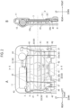
- Fig. 1 is a perspective view of a scientific calculator 1 according to the present embodiment
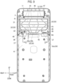
- Fig. 2A is a view of an upper half portion inside the scientific calculator 1 when viewed from a back surface side
- Fig. 2B is a cross-sectional view taken along line II-II of Fig. 2A .
- front, rear, left, right, up, and down directions refer to the directions illustrated in the drawings. That is, a front-rear direction refers to a front surface-back surface direction (thickness direction) of the scientific calculator 1, a left-right direction refers to a width direction of the scientific calculator 1, and an up-down direction refers to a longitudinal direction of the scientific calculator 1.
- the scientific calculator 1 is an example of an electronic apparatus according to the present invention, and is formed in a rectangular plate shape elongated in the up-down direction.
- the scientific calculator 1 includes a front surface case 11 that covers a front surface and a back surface case 12 that covers a back surface (rear surface).
- a liquid crystal display 2 on which various types of information are displayed and a plurality of operating buttons 13 for receiving user operations are disposed.
- the front surface case 11 and the back surface case 12 are engaged in the front-rear direction to constitute a housing of the scientific calculator 1.
- the liquid crystal display 2 and a protective panel 3 thereof are accommodated in the housing defined by the front surface case 11 and the back surface case 12.
- the liquid crystal display 2 is an example of a display unit according to the present invention, and is disposed above the center of the scientific calculator 1 in the up-down direction.
- the liquid crystal display 2 includes a liquid crystal main body 21 and a connector portion 22.
- the liquid crystal main body 21 is formed in a rectangular plate shape that is long in the left-right direction and short in the up-down direction, and a front display surface is exposed to the front of the scientific calculator 1 through the front surface case 11.
- the connector portion 22 is a terminal portion of the liquid crystal display 2 for electrically connecting the liquid crystal main body 21 to a printed circuit board 41 on which a control circuit is mounted, and is provided on a lower side of the liquid crystal main body 21.
- the connector portion 22 is electrically connected to the printed circuit board 41 disposed below the liquid crystal display 2 via a flexible substrate 42 connected to a central portion in the left-right direction.
- the connector portion 22 is positioned on a front side of a rear surface of the liquid crystal main body 21 and is spaced apart from the protective panel 3.
- the protective panel 3 is an example of a support member according to the present invention, and is formed in a rectangular plate shape slightly larger than the liquid crystal display 2.
- the protective panel 3 is disposed in such a way as to cover substantially the entire back surface (rear surface) of the liquid crystal display 2, and is attached to the rear surface of the liquid crystal main body 21 by a double-sided tape (not illustrated) to support the liquid crystal display 2.
- the protective panel 3 of the present embodiment is made of a resin (a resin is contained).
- a portion of the rear surface of the protective panel 3 that corresponds to the liquid crystal display 2 is a reinforcing portion R having an increased rigidity, and a plurality of ribs 30 for reinforcement are erected.
- the reinforcing portion R of the present embodiment is formed in a horizontally symmetrical and vertically asymmetrical shape, and includes a first reinforcing portion R1 corresponding to a position of the liquid crystal main body 21 and a second reinforcing portion R2 provided at the center in the left-right direction below the first reinforcing portion R1.
- the plurality of ribs 30 include a plurality of first ribs 31 extending obliquely with respect to the up-down direction, a plurality of second ribs 32 parallel to the left-right direction, and two third ribs 33 parallel to the up-down direction.
- first ribs 31 are arranged symmetrically with respect to the left-right direction, that is, formed in a line-symmetric shape with respect to a horizontal center line V of the liquid crystal main body 21.
- Each of the plurality of first ribs 31 has a smaller inclination angle with respect to the up-down direction as the first rib 31 is closer to the horizontal center line V, and stands in the up-down direction.
- the plurality of first ribs 31 are arranged asymmetrically with respect to the up-down direction. More specifically, each first rib 31 is bent toward the center in the left-right direction with a position on a vertical center line H of the liquid crystal main body 21 as a bending point, and is inclined in such a way as to approach the horizontal center line V as the distance from the vertical center line H increases. Although the first ribs 31 extend at substantially the same inclination angles above and below the bending point, a distance from the vertical center line H to a lower end is larger than a distance from the vertical center line H to an upper end. Therefore, each of the first ribs 31 is vertically asymmetric.
- second ribs 32 are arranged in the up-down direction at substantially equal intervals.
- a length L3 of a lower end second rib 32b is as small as about 1/3 of lengths (L1 and L2) of the other second ribs 32a, and the lower end second rib 32b is disposed at the center in the left-right direction to connect lower ends of the four first ribs 31.
- the two third ribs 33 are disposed at both left and right ends of the first reinforcing portion R1, and connect left and right ends of the five second ribs 32a. However, a lower end of each third rib 33 is bent in a chamfered shape and connected to the second rib 32a.
- a third rib 33a extends downward from the fifth second rib 32a from the top on each of the slightly outer sides of intersections with the first ribs 31 on both the left and right sides in the left-right direction, the third rib 33a being slightly shorter in the up-down direction.
- One end (lower end) of only the third rib 33a is not connected to the other ribs 30.
- the reinforcing portion R a rectangular portion closed by the upper end, the fifth second rib 32a from the top, and the two left and right third ribs 33 is the first reinforcing portion R1, and a portion below the first reinforcing portion R1 is the second reinforcing portion R2.
- a plurality of recesses 35 surrounded by the plurality of ribs 30 are formed on the rear surface of the protective panel 3. That is, the plurality of recesses 35 are defined by the plurality of first ribs 31, the plurality of second ribs 32, and the two third ribs 33.
- the plurality of recesses 35 are formed to be non-uniform in size, and in the present embodiment, the recesses 35 are substantially smaller in size as the distance from the horizontal center line V of the liquid crystal display 2 (the liquid crystal main body 21) increases. More specifically, among the plurality of recesses 35, a plurality of recesses 35 disposed near the center of the liquid crystal display 2 in a longitudinal direction are roughly distributed as compared with a plurality of recesses 35 disposed near both ends in the longitudinal direction. That is, the plurality of recesses 35 are arranged in such a way that the recesses 35 are more densely provided on left and right end sides than on the center side in the left-right direction.
- the plurality of recesses 35 include recesses having non-uniform sizes (different sizes), and the plurality of recesses 35 may include recesses having the same size.
- a plurality of hooks 36 and extending portions 37 are provided on both left and right sides of a lower end portion of the protective panel 3 (both left and right sides of the second reinforcing portion R2).
- the plurality of hooks 36 are used to lock lead wires (wire rods) 45.
- the lead wire 45 electrically connects a solar panel 43, a battery 44, and the like disposed above the protective panel 3 to the printed circuit board 41, and is routed on or beside the ribs 30. It is sufficient if the hook 36 is provided on at least one side of a portion of the protective panel 3 that corresponds to the connector portion 22 in the left-right direction.
- the extending portions 37 extend downward from lower ends on both left and right sides of the protective panel 3 and support the printed circuit board 41.
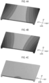
- Figs. 3(a) and 3(b) illustrate main deformation behaviors of the protective panel 3 (analysis model) (deformation magnification: 50 times).
- the protective panel 3 is deformed in such a way that four corners of upper, lower, left, and right covers are lifted ( Fig. 3A ) or deformed in such a way that the center of the lower end is bent ( Fig. 3B ).
- a load simulating the deformation behavior of the protective panel 3 obtained above was set.
- a predetermined forward load was applied to each of both ends of an upper side of the protective panel 3 ( Fig. 4A ), both ends of a lower side of the protective panel 3 ( Fig. 4B ), and the center of the lower end of the protective panel 3 ( Fig. 4C ).
- An optimum shape when the surface of the flat plate model to which the set load is applied is thinned to a predetermined mass was obtained by the topology analysis.
- FIG. 5(a) and 5(b) illustrate thinned portions (portions with light colors) when a target mass is set to a mass reduction of 30% or a mass reduction of 50%.
- a shape close to the protective panel 3 (the rib 30) of the present embodiment was obtained as an optimum shape when the thinning is made in such a way that the mass is reduced by 50%.
- the shape of the protective panel 3 (the rib 30) of the present embodiment and a deformed shape thereof were evaluated by deformation amounts of the protective panel 3 itself and the liquid crystal display 2.
- the analysis model includes the protective panel 3, the liquid crystal display 2, the front surface case 11 (only a portion around the protective panel 3), and the double-sided tape (for bonding the upper and lower ends of the liquid crystal main body 21 to the protective panel 3).
- the protective panel 3 is a model in which the hook 36 and the extending portion 37 are omitted.
- a model without the second reinforcing portion R2 Fig. 6A
- the model of the present embodiment with the second reinforcing portion R2 ( Fig. 6B )
- a model with the second reinforcing portion R2 expanded to have the same width as the first reinforcing portion R1 Fig. 6C ).
- the deformation amount when a predetermined load is applied to a load point P at a lower portion of the center of the protective panel 3 was calculated.
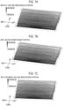
- the deformation amount of the liquid crystal display 2 is illustrated in Fig. 7 .
- the presence or absence of the second reinforcing portion R2 does not significantly affect the deformation amount of the liquid crystal display 2.
- the second reinforcing portion R2 is expanded in the left-right direction (that is, at least the plurality of second ribs 32 have the same length in the left-right direction in the portion corresponding to the connector portion 22 and the portion corresponding to the liquid crystal main body 21)
- the deformation amount of the liquid crystal display 2 can be further decreased.
- the deformation amount of the protective panel 3 is illustrated in Fig. 8 .
- the presence or absence of the second reinforcing portion R2 does not significantly affect the deformation amount of the protective panel 3.
- the deformation amount of the protective panel 3 can be further decreased, similarly to the liquid crystal display 2.
- the protective panel 3 that supports the liquid crystal display 2 includes the plurality of ribs 30 erected on the rear surface and the plurality of recesses 35 surrounded by the plurality of ribs 30, the plurality of recesses 35 including those having non-uniform sizes.
- the density of the recesses 35 can be different between a portion requiring a higher strength (rigidity) and a portion not requiring a higher strength (rigidity). This makes it possible to reduce the weight of the protective panel 3 while appropriately maintaining the rigidity of the protective panel 3, unlike the technology according to the related art in which ribs having a uniform pattern shape are erected.
- the liquid crystal display 2 can be suitably supported.
- the "size" of the recess 35 may include a concept of a volume in consideration of the height of the rib 30 in addition to the area of the recess 35 surrounded by the ribs 30.
- the recesses 35 disposed near the center of the liquid crystal display 2 in the longitudinal direction are roughly distributed as compared with the recesses 35 disposed near both ends in the longitudinal direction.
- the second rib 32b corresponding to the connector portion 22 is shorter in the left-right direction than the second rib 32a corresponding to the liquid crystal main body 21.
- the hook 36 for locking the lead wire 45 can be provided at a lower portion of the protective panel 3 that corresponds to the connector portion 22.
- the lead wire 45 does not interfere during assembly work or the like, and work efficiency of assembly or the like is improved as compared with a case where the hook 36 is not provided. Further, it is possible to suppress an occurrence of a manufacturing defect in which the lead wire 45 is caught when the front surface case 11 and the back surface case 12 are closed.
- the protective panel 3 is made of a resin (a resin is contained), it is not necessary to perform insulation processing on, for example, a metal battery spring or the like extending from a battery box. That is, since the metal battery spring does not have a coating film, in a case of a metal protective panel, at least a portion in contact with the battery spring needs to be insulated.
- the protective panel 3 made of a resin (a resin is contained) for example, even in a case where a battery box 47 accommodating a dry battery 46 is disposed as illustrated in Fig. 9 , a battery spring 48 extending from the battery box 47 can pass on the protective panel 3 without requiring insulation (coating) processing.
- the battery spring 48 since the battery spring 48 is routed instead of the lead wire 45 in the present embodiment, the battery spring 48 can be suitably organized by shortening the second rib 32b in the left-right direction and providing the hook 36 as in a case of the lead wire 45.
- the reason for using the battery spring 48 instead of the lead wire 45 is to enable soldering by an automatic machine and to reduce an assembly time required for wiring. Since the shape of the lead wire 45 is freely changeable, it takes time to wire the lead wire in such a way as not to cause an assembly failure. In this regard, in a case of using the battery spring 48, the cost of the component itself slightly increases, but a work time at the time of assembly can be shortened, so that it is possible to achieve overall cost reduction.
- specific shapes (arrangement, positions, quantities, and the like) of the plurality of ribs 30 are not limited to those of the above embodiment, and it is sufficient if the plurality of recesses 35 include those having non-uniform sizes.
- a pattern of the recesses 35 in which the recesses 35 are more densely provided on both end sides of the liquid crystal display 2 in the longitudinal direction is mainly adopted based on a result of the topology analysis, but the pattern of the recesses 35 in which the recesses 35 are more densely provided near the center according to a difference in liquid crystal to be protected or housing may be adopted.
- the electronic apparatus according to the present invention is not limited to a scientific calculator (electronic desktop calculator), and can be widely applied to general electronic apparatuses including a display unit, such as an electronic dictionary and a smartphone.
- the display unit according to the present invention is not limited to a liquid crystal display unit.
- the present invention is applicable to an electronic apparatus by enabling suitable support for a display unit such as a liquid crystal display.
Landscapes
- Physics & Mathematics (AREA)
- Engineering & Computer Science (AREA)
- Theoretical Computer Science (AREA)
- General Physics & Mathematics (AREA)
- Nonlinear Science (AREA)
- General Engineering & Computer Science (AREA)
- Computer Hardware Design (AREA)
- Chemical & Material Sciences (AREA)
- Crystallography & Structural Chemistry (AREA)
- Human Computer Interaction (AREA)
- Mathematical Physics (AREA)
- Optics & Photonics (AREA)
- Devices For Indicating Variable Information By Combining Individual Elements (AREA)
- Liquid Crystal (AREA)
Abstract
Description
- The present invention relates to an electronic apparatus.
- Hitherto, in an electronic apparatus such as a scientific calculator, a protective panel for supporting a liquid crystal display may be disposed on a back surface of the liquid crystal display. As this type of protective panel, a protective panel made of aluminum is also suitably used, but a protective panel made of a resin is more preferable from the viewpoint of weight reduction.
- In the protective panel made of a resin, a rib may be provided on a back surface of the protective panel for the purpose of improving a strength (rigidity) while reducing a weight. As such a rib, for example, a rib having a uniform pattern shape such as a honeycomb shape or a rhombus shape as described in
Patent Literatures -
- Patent Literature 1:
JP 2012-10414 A - Patent Literature 2:
JP H09-62400 A - However, it is difficult to say that the rib having the uniform pattern shape suitably copes with a load unevenly distributed on the protective panel.
- The present invention has been made in view of the above circumstances, and an object of the present invention is to suitably support a display unit such as a liquid crystal display.
- In order to achieve the above object, the present invention is characterized as including a display unit; and a support member that supports a back surface of the display unit, wherein the support member includes a plurality of ribs erected on a main surface opposite to the display unit, and a plurality of recesses surrounded by the plurality of ribs, and the plurality of recesses include recesses having non-uniform sizes.
- According to the present invention, it is possible to suitably support a display unit.
-
-
Fig. 1 is a perspective view of a scientific calculator according to an embodiment. -
Fig. 2A is a view of an upper half portion inside the scientific calculator when viewed from a back surface side, andFig. 2B is a cross-sectional view taken along line II-II ofFig. 2A . -
Fig. 3 is a view illustrating a deformation behavior analysis result of a protective panel. -
Fig. 4 is a view illustrating a design load of topology analysis. -
Fig. 5 is a view illustrating an analysis result of the topology analysis. -
Fig. 6 is a view illustrating an analysis model of deformation amount analysis. -
Fig. 7 is a view illustrating a deformation amount analysis result of a liquid crystal display. -
Fig. 8 is a view illustrating a deformation amount analysis result of the protective panel. -
Fig. 9 is a view of the inside of the scientific calculator in a case where a battery spring is disposed on the protective panel when viewed from the back surface side. - An embodiment of an electronic apparatus according to the present invention will be described with reference to
Figs. 1 to 9 . - Note that although various technically preferable limitations are given to the embodiment described below in order to carry out the present invention, the scope of the present invention is not limited to the following embodiment and illustrated examples.
-
Fig. 1 is a perspective view of ascientific calculator 1 according to the present embodiment,Fig. 2A is a view of an upper half portion inside thescientific calculator 1 when viewed from a back surface side, andFig. 2B is a cross-sectional view taken along line II-II ofFig. 2A . - Note that in the following description, front, rear, left, right, up, and down directions refer to the directions illustrated in the drawings. That is, a front-rear direction refers to a front surface-back surface direction (thickness direction) of the
scientific calculator 1, a left-right direction refers to a width direction of thescientific calculator 1, and an up-down direction refers to a longitudinal direction of thescientific calculator 1. - As illustrated in
Fig. 1 , thescientific calculator 1 is an example of an electronic apparatus according to the present invention, and is formed in a rectangular plate shape elongated in the up-down direction. Thescientific calculator 1 includes afront surface case 11 that covers a front surface and aback surface case 12 that covers a back surface (rear surface). In thefront surface case 11, aliquid crystal display 2 on which various types of information are displayed and a plurality ofoperating buttons 13 for receiving user operations are disposed. Thefront surface case 11 and theback surface case 12 are engaged in the front-rear direction to constitute a housing of thescientific calculator 1. - As illustrated in
Fig. 2 , theliquid crystal display 2 and aprotective panel 3 thereof are accommodated in the housing defined by thefront surface case 11 and theback surface case 12. - The
liquid crystal display 2 is an example of a display unit according to the present invention, and is disposed above the center of thescientific calculator 1 in the up-down direction. Theliquid crystal display 2 includes a liquid crystalmain body 21 and aconnector portion 22. - The liquid crystal
main body 21 is formed in a rectangular plate shape that is long in the left-right direction and short in the up-down direction, and a front display surface is exposed to the front of thescientific calculator 1 through thefront surface case 11. - The
connector portion 22 is a terminal portion of theliquid crystal display 2 for electrically connecting the liquid crystalmain body 21 to a printedcircuit board 41 on which a control circuit is mounted, and is provided on a lower side of the liquid crystalmain body 21. Theconnector portion 22 is electrically connected to the printedcircuit board 41 disposed below theliquid crystal display 2 via aflexible substrate 42 connected to a central portion in the left-right direction. Theconnector portion 22 is positioned on a front side of a rear surface of the liquid crystalmain body 21 and is spaced apart from theprotective panel 3. - The
protective panel 3 is an example of a support member according to the present invention, and is formed in a rectangular plate shape slightly larger than theliquid crystal display 2. Theprotective panel 3 is disposed in such a way as to cover substantially the entire back surface (rear surface) of theliquid crystal display 2, and is attached to the rear surface of the liquid crystalmain body 21 by a double-sided tape (not illustrated) to support theliquid crystal display 2. Theprotective panel 3 of the present embodiment is made of a resin (a resin is contained). - A portion of the rear surface of the
protective panel 3 that corresponds to theliquid crystal display 2 is a reinforcing portion R having an increased rigidity, and a plurality ofribs 30 for reinforcement are erected. The reinforcing portion R of the present embodiment is formed in a horizontally symmetrical and vertically asymmetrical shape, and includes a first reinforcing portion R1 corresponding to a position of the liquid crystalmain body 21 and a second reinforcing portion R2 provided at the center in the left-right direction below the first reinforcing portion R1. - Specifically, the plurality of
ribs 30 include a plurality offirst ribs 31 extending obliquely with respect to the up-down direction, a plurality ofsecond ribs 32 parallel to the left-right direction, and twothird ribs 33 parallel to the up-down direction. - In the present embodiment, four
first ribs 31 are arranged symmetrically with respect to the left-right direction, that is, formed in a line-symmetric shape with respect to a horizontal center line V of the liquid crystalmain body 21. Each of the plurality offirst ribs 31 has a smaller inclination angle with respect to the up-down direction as thefirst rib 31 is closer to the horizontal center line V, and stands in the up-down direction. - The plurality of
first ribs 31 are arranged asymmetrically with respect to the up-down direction. More specifically, eachfirst rib 31 is bent toward the center in the left-right direction with a position on a vertical center line H of the liquid crystalmain body 21 as a bending point, and is inclined in such a way as to approach the horizontal center line V as the distance from the vertical center line H increases. Although thefirst ribs 31 extend at substantially the same inclination angles above and below the bending point, a distance from the vertical center line H to a lower end is larger than a distance from the vertical center line H to an upper end. Therefore, each of thefirst ribs 31 is vertically asymmetric. - In the present embodiment, six
second ribs 32 are arranged in the up-down direction at substantially equal intervals. However, only a length L3 of a lower endsecond rib 32b is as small as about 1/3 of lengths (L1 and L2) of the othersecond ribs 32a, and the lower endsecond rib 32b is disposed at the center in the left-right direction to connect lower ends of the fourfirst ribs 31. - The two
third ribs 33 are disposed at both left and right ends of the first reinforcing portion R1, and connect left and right ends of the fivesecond ribs 32a. However, a lower end of eachthird rib 33 is bent in a chamfered shape and connected to thesecond rib 32a. Athird rib 33a extends downward from the fifthsecond rib 32a from the top on each of the slightly outer sides of intersections with thefirst ribs 31 on both the left and right sides in the left-right direction, thethird rib 33a being slightly shorter in the up-down direction. One end (lower end) of only thethird rib 33a is not connected to theother ribs 30. - In the reinforcing portion R, a rectangular portion closed by the upper end, the fifth
second rib 32a from the top, and the two left and rightthird ribs 33 is the first reinforcing portion R1, and a portion below the first reinforcing portion R1 is the second reinforcing portion R2. - By arranging the plurality of
ribs 30 as described above, a plurality ofrecesses 35 surrounded by the plurality ofribs 30 are formed on the rear surface of theprotective panel 3. That is, the plurality ofrecesses 35 are defined by the plurality offirst ribs 31, the plurality ofsecond ribs 32, and the twothird ribs 33. - The plurality of
recesses 35 are formed to be non-uniform in size, and in the present embodiment, therecesses 35 are substantially smaller in size as the distance from the horizontal center line V of the liquid crystal display 2 (the liquid crystal main body 21) increases. More specifically, among the plurality ofrecesses 35, a plurality ofrecesses 35 disposed near the center of theliquid crystal display 2 in a longitudinal direction are roughly distributed as compared with a plurality ofrecesses 35 disposed near both ends in the longitudinal direction. That is, the plurality ofrecesses 35 are arranged in such a way that therecesses 35 are more densely provided on left and right end sides than on the center side in the left-right direction. - It is sufficient if the plurality of
recesses 35 include recesses having non-uniform sizes (different sizes), and the plurality ofrecesses 35 may include recesses having the same size. - A plurality of
hooks 36 and extendingportions 37 are provided on both left and right sides of a lower end portion of the protective panel 3 (both left and right sides of the second reinforcing portion R2). - The plurality of
hooks 36 are used to lock lead wires (wire rods) 45. Thelead wire 45 electrically connects asolar panel 43, abattery 44, and the like disposed above theprotective panel 3 to the printedcircuit board 41, and is routed on or beside theribs 30. It is sufficient if thehook 36 is provided on at least one side of a portion of theprotective panel 3 that corresponds to theconnector portion 22 in the left-right direction. - The extending
portions 37 extend downward from lower ends on both left and right sides of theprotective panel 3 and support the printedcircuit board 41. - Next, an analysis for obtaining a shape of the
rib 30 will be described. - In the analysis, first, a deformation behavior of the
protective panel 3 when an external force is applied to thescientific calculator 1 was confirmed. A simple flat plate model without therib 30 was used as theprotective panel 3, and calculation in a case where theprotective panel 3 was dropped from each of the front surface side and the back surface side in a state of being accommodated in thescientific calculator 1 was performed. -
Figs. 3(a) and 3(b) illustrate main deformation behaviors of the protective panel 3 (analysis model) (deformation magnification: 50 times). As illustrated inFig. 3 , in a case where thescientific calculator 1 is dropped, theprotective panel 3 is deformed in such a way that four corners of upper, lower, left, and right covers are lifted (Fig. 3A ) or deformed in such a way that the center of the lower end is bent (Fig. 3B ). - Next, an optimum shape of the protective panel 3 (the rib 30) was obtained by topology analysis.
- Here, a load simulating the deformation behavior of the
protective panel 3 obtained above was set. As illustrated inFig. 4 , as the set load, a predetermined forward load was applied to each of both ends of an upper side of the protective panel 3 (Fig. 4A ), both ends of a lower side of the protective panel 3 (Fig. 4B ), and the center of the lower end of the protective panel 3 (Fig. 4C ). An optimum shape when the surface of the flat plate model to which the set load is applied is thinned to a predetermined mass was obtained by the topology analysis. - Analysis results are illustrated in
Fig. 5. Figs. 5(a) and 5(b) illustrate thinned portions (portions with light colors) when a target mass is set to a mass reduction of 30% or a mass reduction of 50%. As illustrated inFigs. 5(a) and 5(b) , a shape close to the protective panel 3 (the rib 30) of the present embodiment was obtained as an optimum shape when the thinning is made in such a way that the mass is reduced by 50%. - Next, analysis for evaluating the shape of the
rib 30 will be described. - In the analysis, the shape of the protective panel 3 (the rib 30) of the present embodiment and a deformed shape thereof were evaluated by deformation amounts of the
protective panel 3 itself and theliquid crystal display 2. - Analysis models are illustrated in
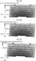
Fig. 6 . The analysis model includes theprotective panel 3, theliquid crystal display 2, the front surface case 11 (only a portion around the protective panel 3), and the double-sided tape (for bonding the upper and lower ends of the liquid crystalmain body 21 to the protective panel 3). However, theprotective panel 3 is a model in which thehook 36 and the extendingportion 37 are omitted. In addition, as the analysis models, a model without the second reinforcing portion R2 (Fig. 6A ) and the model of the present embodiment (with the second reinforcing portion R2 (Fig. 6B )) and a model with the second reinforcing portion R2 expanded to have the same width as the first reinforcing portion R1 (Fig. 6C ). For each of the analysis models, the deformation amount when a predetermined load is applied to a load point P at a lower portion of the center of theprotective panel 3 was calculated. - The deformation amount of the
liquid crystal display 2 is illustrated inFig. 7 . - As illustrated in
Fig. 7 , the presence or absence of the second reinforcing portion R2 does not significantly affect the deformation amount of theliquid crystal display 2. However, when the second reinforcing portion R2 is expanded in the left-right direction (that is, at least the plurality ofsecond ribs 32 have the same length in the left-right direction in the portion corresponding to theconnector portion 22 and the portion corresponding to the liquid crystal main body 21), the deformation amount of theliquid crystal display 2 can be further decreased. - The deformation amount of the
protective panel 3 is illustrated inFig. 8 . - As illustrated in
Fig. 8 , the presence or absence of the second reinforcing portion R2 does not significantly affect the deformation amount of theprotective panel 3. However, when the second reinforcing portion R2 is expanded in the left-right direction, the deformation amount of theprotective panel 3 can be further decreased, similarly to theliquid crystal display 2. - As described above, according to the present embodiment, the
protective panel 3 that supports theliquid crystal display 2 includes the plurality ofribs 30 erected on the rear surface and the plurality ofrecesses 35 surrounded by the plurality ofribs 30, the plurality ofrecesses 35 including those having non-uniform sizes. - That is, the density of the
recesses 35 can be different between a portion requiring a higher strength (rigidity) and a portion not requiring a higher strength (rigidity). This makes it possible to reduce the weight of theprotective panel 3 while appropriately maintaining the rigidity of theprotective panel 3, unlike the technology according to the related art in which ribs having a uniform pattern shape are erected. - Therefore, the
liquid crystal display 2 can be suitably supported. - Here, the "size" of the
recess 35 may include a concept of a volume in consideration of the height of therib 30 in addition to the area of therecess 35 surrounded by theribs 30. - Further, according to the present embodiment, among the plurality of
recesses 35, therecesses 35 disposed near the center of theliquid crystal display 2 in the longitudinal direction are roughly distributed as compared with therecesses 35 disposed near both ends in the longitudinal direction. - As a result, it is possible to reduce the weight of the central portion of the
protective panel 3 in the left-right direction to which a larger load is applied while increasing the rigidity of both of the left and right sides of theprotective panel 3 to which a smaller load is applied. - According to the present embodiment, among the plurality of
second ribs 32, thesecond rib 32b corresponding to theconnector portion 22 is shorter in the left-right direction than thesecond rib 32a corresponding to the liquid crystalmain body 21. - As a result, the
hook 36 for locking thelead wire 45 can be provided at a lower portion of theprotective panel 3 that corresponds to theconnector portion 22. As a result, thelead wire 45 does not interfere during assembly work or the like, and work efficiency of assembly or the like is improved as compared with a case where thehook 36 is not provided. Further, it is possible to suppress an occurrence of a manufacturing defect in which thelead wire 45 is caught when thefront surface case 11 and theback surface case 12 are closed. - In addition, according to the present embodiment, since the
protective panel 3 is made of a resin (a resin is contained), it is not necessary to perform insulation processing on, for example, a metal battery spring or the like extending from a battery box. That is, since the metal battery spring does not have a coating film, in a case of a metal protective panel, at least a portion in contact with the battery spring needs to be insulated. In this regard, in theprotective panel 3 made of a resin (a resin is contained), for example, even in a case where abattery box 47 accommodating adry battery 46 is disposed as illustrated inFig. 9 , abattery spring 48 extending from thebattery box 47 can pass on theprotective panel 3 without requiring insulation (coating) processing. In this case, since thebattery spring 48 is routed instead of thelead wire 45 in the present embodiment, thebattery spring 48 can be suitably organized by shortening thesecond rib 32b in the left-right direction and providing thehook 36 as in a case of thelead wire 45. - In a case of using the
dry battery 46, the reason for using thebattery spring 48 instead of thelead wire 45 is to enable soldering by an automatic machine and to reduce an assembly time required for wiring. Since the shape of thelead wire 45 is freely changeable, it takes time to wire the lead wire in such a way as not to cause an assembly failure. In this regard, in a case of using thebattery spring 48, the cost of the component itself slightly increases, but a work time at the time of assembly can be shortened, so that it is possible to achieve overall cost reduction. - Note that an embodiment to which the present invention can be applied is not limited to the above-described embodiment, and it goes without saying that various modifications can be made without departing from the gist of the present invention.
- For example, specific shapes (arrangement, positions, quantities, and the like) of the plurality of ribs 30 (recesses 35) are not limited to those of the above embodiment, and it is sufficient if the plurality of
recesses 35 include those having non-uniform sizes. - Further, in the present embodiment, a pattern of the
recesses 35 in which therecesses 35 are more densely provided on both end sides of theliquid crystal display 2 in the longitudinal direction is mainly adopted based on a result of the topology analysis, but the pattern of therecesses 35 in which therecesses 35 are more densely provided near the center according to a difference in liquid crystal to be protected or housing may be adopted. - In addition, the electronic apparatus according to the present invention is not limited to a scientific calculator (electronic desktop calculator), and can be widely applied to general electronic apparatuses including a display unit, such as an electronic dictionary and a smartphone.
- In addition, the display unit according to the present invention is not limited to a liquid crystal display unit.
- Although some embodiments of the present invention have been described above, the scope of the present invention is not limited to the above-described embodiments, and includes the scope of the invention described in the claims and the equivalent scope thereof.
- The present invention is applicable to an electronic apparatus by enabling suitable support for a display unit such as a liquid crystal display.
-
- 1
- Scientific calculator (electronic apparatus)
- 2
- Liquid crystal display (display unit)
- 3
- Protective panel (support member)
- 11
- Front surface case
- 12
- Back surface case
- 21
- Liquid crystal main body (main body portion)
- 22
- Connector portion
- 30
- Rib
- 31
- First rib
- 32, 32a, 32b
- Second rib
- 33, 33a
- Third rib
- 35
- Recess
- 36
- Hook
- 41
- Printed circuit board
- H
- Vertical center line
- V
- Horizontal center line
- R
- Reinforcing portion
- R1
- First reinforcing portion
- R2
- Second reinforcing portion
Claims (10)
- An electronic apparatus comprising:a display unit; anda support member that supports a back surface of the display unit, whereinthe support member includes a plurality of ribs erected on a main surface opposite to the display unit, and a plurality of recesses surrounded by the plurality of ribs, andthe plurality of recesses include recesses having non-uniform sizes.
- The electronic apparatus according to claim 1, wherein
among the plurality of recesses, a plurality of recesses disposed near a center of the display unit in a longitudinal direction are roughly distributed as compared with a plurality of recesses disposed near both ends of the display unit in the longitudinal direction. - The electronic apparatus according to claim 1 or 2, whereinthe plurality of ribs include a plurality of first ribs extending obliquely with respect to a first direction corresponding to a lateral direction of the display unit, andthe plurality of first ribs are arranged asymmetrically with respect to the first direction.
- The electronic apparatus according to claim 3, wherein
the plurality of first ribs are arranged symmetrically with respect to a second direction corresponding to a longitudinal direction of the display unit, the longitudinal direction being orthogonal to the lateral direction. - The electronic apparatus according to claim 3, whereinthe plurality of ribs include a plurality of second ribs parallel to a second direction corresponding to a longitudinal direction of the display unit, the longitudinal direction being orthogonal to the lateral direction, andthe plurality of recesses include recesses defined by the plurality of first ribs and the plurality of second ribs.
- The electronic apparatus according to claim 1, wherein
the support member contains a resin. - The electronic apparatus according to claim 6, whereinthe display unit includes a connector portion on one side in a lateral direction and at a central portion in a longitudinal direction,the connector portion is further spaced apart from the support member than a main body portion of the display unit,the plurality of ribs include a plurality of second ribs parallel to a second direction corresponding to the longitudinal direction, andin the plurality of second ribs, a portion corresponding to the connector portion and a portion corresponding to the main body portion have the same length in the longitudinal direction.
- The electronic apparatus according to claim 6, whereinthe display unit includes a connector portion on one side in a lateral direction and at a central portion in a longitudinal direction,the connector portion is further spaced apart from the support member than a main body portion of the display unit,the plurality of ribs include a plurality of second ribs parallel to a second direction corresponding to the longitudinal direction, andin the plurality of second ribs, a portion corresponding to the connector portion is shorter than a portion corresponding to the main body portion in the longitudinal direction.
- The electronic apparatus according to claim 8, wherein
the support member includes a hook for locking a wire rod on at least one side of the portion corresponding to the connector portion in the longitudinal direction. - The electronic apparatus according to claim 8, wherein
each of the plurality of ribs is arranged based on a result of topology analysis.
Applications Claiming Priority (3)
| Application Number | Priority Date | Filing Date | Title |
|---|---|---|---|
| JP2021202951 | 2021-12-15 | ||
| JP2022062208A JP7567850B2 (en) | 2021-12-15 | 2022-04-04 | Electronics |
| PCT/JP2022/039346 WO2023112484A1 (en) | 2021-12-15 | 2022-10-21 | Electronic apparatus |
Publications (2)
| Publication Number | Publication Date |
|---|---|
| EP4451249A1 true EP4451249A1 (en) | 2024-10-23 |
| EP4451249A4 EP4451249A4 (en) | 2025-11-26 |
Family
ID=86774449
Family Applications (1)
| Application Number | Title | Priority Date | Filing Date |
|---|---|---|---|
| EP22907018.0A Pending EP4451249A4 (en) | 2021-12-15 | 2022-10-21 | ELECTRONIC DEVICE |
Country Status (6)
| Country | Link |
|---|---|
| US (1) | US20250123511A1 (en) |
| EP (1) | EP4451249A4 (en) |
| JP (3) | JP7567850B2 (en) |
| CN (1) | CN118382883A (en) |
| AU (1) | AU2022412170B2 (en) |
| WO (1) | WO2023112484A1 (en) |
Families Citing this family (1)
| Publication number | Priority date | Publication date | Assignee | Title |
|---|---|---|---|---|
| JP7732493B2 (en) * | 2023-12-14 | 2025-09-02 | カシオ計算機株式会社 | Covered electronic devices |
Family Cites Families (16)
| Publication number | Priority date | Publication date | Assignee | Title |
|---|---|---|---|---|
| JPH0962400A (en) | 1995-08-23 | 1997-03-07 | Fujitsu Ltd | Information processing device |
| KR100269943B1 (en) * | 1997-03-03 | 2000-10-16 | 윤종용 | All-in-one display module |
| JP2000112370A (en) | 1998-10-06 | 2000-04-21 | Matsushita Electric Ind Co Ltd | Video display device |
| JP2001337611A (en) * | 2000-03-22 | 2001-12-07 | Furukawa Electric Co Ltd:The | Display frame |
| JP4528590B2 (en) * | 2004-09-28 | 2010-08-18 | 株式会社東芝 | Electronics |
| CN103430227B (en) * | 2011-02-10 | 2016-04-13 | Nec显示器解决方案株式会社 | Display device |
| JP5121962B2 (en) * | 2011-03-31 | 2013-01-16 | 株式会社東芝 | Electronics |
| JP4910072B2 (en) * | 2011-08-12 | 2012-04-04 | 株式会社東芝 | Electronics |
| JP4982622B2 (en) | 2011-10-11 | 2012-07-25 | 株式会社東芝 | Television receiver and electronic device |
| JP5977020B2 (en) * | 2011-11-29 | 2016-08-24 | 旭化成株式会社 | Rib design method, rib design apparatus, and rib design program |
| CN103511810A (en) * | 2012-06-28 | 2014-01-15 | 鸿富锦精密工业(深圳)有限公司 | Base and displayer with base |
| CN106021797B (en) * | 2016-06-02 | 2019-04-02 | 武汉船用机械有限责任公司 | A design method of crane ring beam |
| US20180213656A1 (en) * | 2017-01-20 | 2018-07-26 | Canon Kabushiki Kaisha | Decompression container, processing apparatus, processing system, and method of producing flat panel display |
| CN207783372U (en) * | 2018-01-26 | 2018-08-28 | 佳能企业股份有限公司 | Electronic device and stop structure thereof |
| CN210609991U (en) * | 2019-08-15 | 2020-05-22 | 深圳利亚德光电有限公司 | Display screen box body structure and LED display screen with same |
| CN211858000U (en) * | 2020-04-20 | 2020-11-03 | 深圳视爵光旭电子有限公司 | LED display screen module and bottom shell thereof |
-
2022
- 2022-04-04 JP JP2022062208A patent/JP7567850B2/en active Active
- 2022-10-21 CN CN202280082441.3A patent/CN118382883A/en active Pending
- 2022-10-21 AU AU2022412170A patent/AU2022412170B2/en active Active
- 2022-10-21 US US18/720,239 patent/US20250123511A1/en active Pending
- 2022-10-21 EP EP22907018.0A patent/EP4451249A4/en active Pending
- 2022-10-21 WO PCT/JP2022/039346 patent/WO2023112484A1/en not_active Ceased
-
2024
- 2024-10-01 JP JP2024171911A patent/JP7845432B2/en active Active
- 2024-10-01 JP JP2024171912A patent/JP7729449B2/en active Active
Also Published As
| Publication number | Publication date |
|---|---|
| CN118382883A (en) | 2024-07-23 |
| JP2024177262A (en) | 2024-12-19 |
| AU2022412170A1 (en) | 2024-06-06 |
| JP2024177263A (en) | 2024-12-19 |
| US20250123511A1 (en) | 2025-04-17 |
| JP7567850B2 (en) | 2024-10-16 |
| JP7845432B2 (en) | 2026-04-14 |
| EP4451249A4 (en) | 2025-11-26 |
| JP7729449B2 (en) | 2025-08-26 |
| AU2022412170B2 (en) | 2025-05-29 |
| JP2023088821A (en) | 2023-06-27 |
| WO2023112484A1 (en) | 2023-06-22 |
Similar Documents
| Publication | Publication Date | Title |
|---|---|---|
| CN101783451B (en) | Card connector | |
| JP5547818B2 (en) | Printed circuit board | |
| JP5714716B2 (en) | Power control device | |
| JP2014026765A (en) | Connector | |
| JP2019192336A (en) | Wiring module | |
| US20250123511A1 (en) | Electronic apparatus | |
| CN102916270A (en) | Electronic apparatus | |
| JP6960996B2 (en) | Electronic device | |
| JP4956421B2 (en) | Metal core board reinforcement structure and electrical junction box | |
| JP2010216928A (en) | Burn-in test board | |
| CN219227935U (en) | Flexible circuit board and display module | |
| CN105517331A (en) | Circuit board and mobile terminal | |
| CN109994865A (en) | The manufacturing method of connector, connector assembly and connector | |
| JP5507658B2 (en) | Electrical connection device | |
| JP6807549B2 (en) | Housing and remote control device | |
| EP4615178A1 (en) | Communication apparatus and bracket thereof | |
| JP7248718B2 (en) | Composite substrates and electrical devices | |
| JP7035847B2 (en) | Power storage device | |
| KR101646826B1 (en) | Curved PCM | |
| JP4676299B2 (en) | Circuit board structure | |
| JP4407931B2 (en) | Solar electric module with terminal box connected using pull-out rivets | |
| KR20260047102A (en) | Hold-downs and connector including the same | |
| JP6430899B2 (en) | Circuit module | |
| JP2016078545A (en) | Case for on-vehicle electronic unit | |
| JP2010161831A (en) | Electrical junction box |
Legal Events
| Date | Code | Title | Description |
|---|---|---|---|
| STAA | Information on the status of an ep patent application or granted ep patent |
Free format text: STATUS: THE INTERNATIONAL PUBLICATION HAS BEEN MADE |
|
| PUAI | Public reference made under article 153(3) epc to a published international application that has entered the european phase |
Free format text: ORIGINAL CODE: 0009012 |
|
| STAA | Information on the status of an ep patent application or granted ep patent |
Free format text: STATUS: REQUEST FOR EXAMINATION WAS MADE |
|
| 17P | Request for examination filed |
Effective date: 20240610 |
|
| AK | Designated contracting states |
Kind code of ref document: A1 Designated state(s): AL AT BE BG CH CY CZ DE DK EE ES FI FR GB GR HR HU IE IS IT LI LT LU LV MC ME MK MT NL NO PL PT RO RS SE SI SK SM TR |
|
| DAV | Request for validation of the european patent (deleted) | ||
| DAX | Request for extension of the european patent (deleted) | ||
| REG | Reference to a national code |
Ref country code: DE Ref legal event code: R079 Free format text: PREVIOUS MAIN CLASS: G09F0009000000 Ipc: G06F0001160000 |
|
| A4 | Supplementary search report drawn up and despatched |
Effective date: 20251028 |
|
| RIC1 | Information provided on ipc code assigned before grant |
Ipc: G06F 1/16 20060101AFI20251022BHEP Ipc: G02F 1/1333 20060101ALI20251022BHEP Ipc: G09F 9/35 20060101ALI20251022BHEP |