JP5977020B2 - Rib design method, rib design apparatus, and rib design program - Google Patents
Rib design method, rib design apparatus, and rib design program Download PDFInfo
- Publication number
- JP5977020B2 JP5977020B2 JP2011260228A JP2011260228A JP5977020B2 JP 5977020 B2 JP5977020 B2 JP 5977020B2 JP 2011260228 A JP2011260228 A JP 2011260228A JP 2011260228 A JP2011260228 A JP 2011260228A JP 5977020 B2 JP5977020 B2 JP 5977020B2
- Authority
- JP
- Japan
- Prior art keywords
- shell
- rib
- optimization
- article
- information
- Prior art date
- Legal status (The legal status is an assumption and is not a legal conclusion. Google has not performed a legal analysis and makes no representation as to the accuracy of the status listed.)
- Active
Links
Images


Classifications
-
- Y—GENERAL TAGGING OF NEW TECHNOLOGICAL DEVELOPMENTS; GENERAL TAGGING OF CROSS-SECTIONAL TECHNOLOGIES SPANNING OVER SEVERAL SECTIONS OF THE IPC; TECHNICAL SUBJECTS COVERED BY FORMER USPC CROSS-REFERENCE ART COLLECTIONS [XRACs] AND DIGESTS
- Y02—TECHNOLOGIES OR APPLICATIONS FOR MITIGATION OR ADAPTATION AGAINST CLIMATE CHANGE
- Y02T—CLIMATE CHANGE MITIGATION TECHNOLOGIES RELATED TO TRANSPORTATION
- Y02T10/00—Road transport of goods or passengers
- Y02T10/80—Technologies aiming to reduce greenhouse gasses emissions common to all road transportation technologies
- Y02T10/82—Elements for improving aerodynamics
Description
本発明は、自動車部品等の強度を補強するためのリブを設計するリブ設計技術に関する。 The present invention relates to a rib design technique for designing a rib for reinforcing the strength of an automobile part or the like.
従来、例えば自動車の部品等を軽量化する方法として、部品の材料をアルミ等の金属から、より軽量なプラスチック樹脂等の素材に変更することが行われている。しかし、部品をプラスチック製にした場合、金属製である場合よりも部品の強度が弱くなってしまうため、リブを新たに設計して部品の強度を補強する場合がある。
このようなリブの設計を行う際、一般的に、設計者は、非特許文献1のような設計支援ソフトウェアを使用して設計を行う。非特許文献1のソフトウェアは、設計者が既存部品の形状データを入力し、制約条件や目的関数等を設定すると、自動的にトポロジー最適化処理を行って、既存部品の形状にリブを設けた最適化形状を生成して出力する。そして、設計者は、ソフトウェアが出力した最適化形状が設定した制約条件等の条件を満たすものであるかをテストし、条件を満たさない場合には、再度、制約条件等の条件をソフトウェアに入力し直して、最適化形状を出力させるということを繰り返し、最終的な物品形状を決定する。
Conventionally, for example, as a method for reducing the weight of automobile parts or the like, the material of the parts has been changed from a metal such as aluminum to a material such as a lighter plastic resin. However, when the parts are made of plastic, the strength of the parts is weaker than when the parts are made of metal. Therefore, the ribs may be newly designed to reinforce the strength of the parts.
When designing such ribs, a designer generally performs design using design support software such as Non-Patent Document 1. In the software of Non-Patent Document 1, when a designer inputs shape data of an existing part and sets constraints, objective functions, etc., a topology optimization process is automatically performed, and a rib is provided on the shape of the existing part. Generate and output an optimized shape. Then, the designer tests whether the optimized shape output by the software satisfies the conditions such as the constraints set, and if the conditions are not satisfied, inputs the conditions such as the constraints again into the software. The final product shape is determined by repeating the process of outputting the optimized shape again.
ところで、非特許文献1の設計支援ソフトウェアで一般的に推奨されているリブ設計方法は、既存部品の形状に肉付けしたソリッド状の設計空間(形状変更に使用可能な空間)を設計者に設定させ、この設計空間から不要部分を削ってリブを生成するものである。
しかしながら、このリブ設計方法を用いると、最終的にソフトウェアが出力する最適化形状は、余分な部位が残っている等の理由により、実際にそのまま部品として使用できるような適切な形状でない場合が多い。このため、再度、設計者が制約条件や目的関数の設定をし直して、ソフトウェアに再設計させるということを繰り返さなければならないという問題があった。また、このリブ設計方法は、計算量が多くなり、ソフトウェアから最適化形状が出力されるまでに時間がかかるという問題があった。
By the way, the rib design method generally recommended in the design support software of Non-Patent Document 1 allows the designer to set a solid design space (space that can be used for shape change) that is fleshed out to the shape of an existing part. The ribs are generated by cutting unnecessary portions from the design space.
However, when this rib design method is used, the optimized shape that is finally output by the software is often not an appropriate shape that can be used as a part as it is because of the extra portion remaining. . For this reason, there has been a problem that the designer has to repeat the setting of the constraint condition and the objective function and causing the software to redesign. In addition, this rib design method has a problem that the calculation amount increases, and it takes time until the optimized shape is output from the software.
そこで、本発明は上記課題に鑑み、より計算量が少なく、より適切な最適化形状を出力することが可能なリブ設計方法、リブ設計装置、およびリブ設計プログラムを提供することを目的とする。 In view of the above problems, an object of the present invention is to provide a rib design method, a rib design apparatus, and a rib design program that can output a more appropriate optimized shape with less calculation amount.
上記問題を解決するために、本発明の一態様によれば、物品の3次元形状データを取得する形状データ取得部と、前記形状データ取得部に接続されているシェル情報取得部と、前記シェル情報取得部に接続されているシェル分割部と、前記物品の境界条件を取得する境界条件取得部と、前記境界条件取得部に接続されている最適化条件取得部と、前記シェル分割部と前記最適化条件取得部に接続されている最適化処理部と、前記最適化処理部に接続されているリブ生成部と、を有するリブ設計装置が実行し、トポロジー最適化処理を行って物品のリブを設計するリブ設計方法であって、前記形状データ取得部が、前記物品の形状を示す3次元形状データを取得する第1のステップと、前記シェル情報取得部が、前記物品の形状の少なくとも一部を含む空間モデルを設計し、当該空間モデル内において、リブを設ける前記物品の略面形状部分に対して設定される、シェルの範囲を示す2次元座標と前記シェルの厚みを示す厚み情報とからなる2.5次元情報の面状のシェルモデルを取得する第2のステップと、前記シェル分割部が、前記シェルモデルをメッシュ状の複数の要素に分割する第3のステップと、前記境界条件取得部が、前記物品が使用される際の使用条件を示す境界条件を取得する第4のステップと、前記最適化条件取得部が、前記境界条件に対応した制約条件と、目的関数と、を含む最適化条件を取得する第5のステップと、前記最適化処理部が、前記第3のステップにおいて前記メッシュ状の複数の要素に分割された前記シェルモデルに対して、前記最適化条件取得部で取得された前記最適化条件を満たすようにトポロジー最適化処理を行い、最適化処理後の最適形状を表す情報の密度分布情報である最適形状情報を出力する第6のステップと、前記リブ生成部が、前記最適形状情報に対応するようにリブを生成する第7のステップと、を含むことを特徴とするリブ設計方法が提供される。 In order to solve the above problem, according to one aspect of the present invention, a shape data acquisition unit that acquires three-dimensional shape data of an article, a shell information acquisition unit connected to the shape data acquisition unit, and the shell A shell dividing unit connected to the information obtaining unit, a boundary condition obtaining unit for obtaining a boundary condition of the article, an optimization condition obtaining unit connected to the boundary condition obtaining unit, the shell dividing unit, and the A rib designing apparatus having an optimization processing unit connected to the optimization condition acquisition unit and a rib generation unit connected to the optimization processing unit executes the topology optimization processing and executes the rib of the article The rib design method of designing the first step, wherein the shape data acquisition unit acquires three-dimensional shape data indicating the shape of the article, and the shell information acquisition unit includes at least one of the shapes of the article. We designed a space model comprising, from within the space model, set for a substantially plane-shaped portion of the article providing the ribs, and the thickness information indicating a thickness of the shell and the two-dimensional coordinates indicating the range of the shell A second step of acquiring a planar shell model of 2.5D information, a third step of the shell dividing unit dividing the shell model into a plurality of mesh elements, and acquiring the boundary condition A fourth step of acquiring a boundary condition indicating a use condition when the article is used, and the optimization condition acquiring unit includes a constraint condition corresponding to the boundary condition and an objective function a fifth step of obtaining the optimum conditions, the optimization processing unit, with respect to the third of the shell model divided into a plurality of elements of the mesh-like in step, the optimized condition acquisition In performs the acquired optimized conditions topology optimization process to meet, and a sixth step of outputting the optimum shape information is the density distribution information of information representing the optimum shape after optimization, the rib generation And a seventh step of generating a rib so as to correspond to the optimum shape information . A rib design method is provided.
この構成によれば、従来のようにソリッド状の設計空間を用いずに、2.5次元という、より少ないデータ量からリブを生成するため、計算量が少なくて済む。また、面状のシェルモデルからリブを生成するため、従来のように余分な部位が残った最適化形状が出力される可能性が低く、より適切な最適化形状を得ることが可能である。
また、本発明の他の態様によれば、トポロジー最適化処理を行って物品のリブを設計するリブ設計装置であって、前記物品の形状を示す3次元形状データを取得する形状データ取得部と、前記形状データ取得部で取得された前記3次元形状データである前記物品の形状の少なくとも一部を含む空間モデルを設計し、当該空間モデル内において、前記リブを設ける前記物品の略面形状部分に対して設定される、シェルの範囲を示す2次元座標と前記シェルの厚みを示す厚み情報とからなる2.5次元情報の面状のシェルモデルを取得するシェル情報取得部と、前記シェル情報取得部で取得された前記シェルモデルをメッシュ状の複数の要素に分割するシェル分割部と、前記物品が使用される際の使用条件を示す境界条件を取得する境界条件取得部と、前記境界条件取得部で取得された前記境界条件に対応した制約条件と、目的関数と、を含む最適化条件を取得する最適化条件取得部と、前記シェル分割部において前記メッシュ状の複数の要素に分割された前記シェルモデルに対して、前記最適化条件取得部で取得された前記最適化条件を満たすようにトポロジー最適化処理を行い、最適化処理後の最適形状を表す情報の密度分布情報である最適形状情報を出力する最適化処理部と、前記最適化処理部で出力された前記最適形状情報に対応するようにリブを生成するリブ生成部と、を有することを特徴とするリブ設計装置が提供される。
According to this configuration, since a rib is generated from a smaller data amount of 2.5 dimensions without using a solid design space as in the prior art, the calculation amount can be reduced. Further, since the rib is generated from the planar shell model, it is unlikely that an optimized shape with an extra portion remaining as in the conventional case is output, and a more appropriate optimized shape can be obtained.
According to another aspect of the present invention, there is provided a rib design device that performs a topology optimization process to design a rib of an article, and a shape data acquisition unit that acquires three-dimensional shape data indicating the shape of the article; at least a portion designed a space model comprising a substantially plane-shaped portion of the article within the space model, providing the ribs of the shape of the article which is the three-dimensional shape data obtained by the shape data acquiring unit A shell information acquisition unit configured to acquire a planar shell model of 2.5D information composed of two-dimensional coordinates indicating a range of the shell and thickness information indicating the thickness of the shell, and the shell information a shell dividing unit for dividing the shell model acquired by the acquisition unit into a plurality of elements of the mesh-like boundary conditions acquisition for acquiring boundary condition indicating a use condition when the article is used When a constraint condition corresponding to been the boundary conditions obtained in the boundary condition acquisition unit, and optimization condition acquisition unit that acquires an optimization condition including a objective function, a plurality of the mesh-like in the shell dividing portion The density of information representing the optimum shape after the optimization processing is performed on the shell model divided into the elements of the topology optimization process so as to satisfy the optimization condition acquired by the optimization condition acquisition unit An optimization processing unit that outputs optimal shape information that is distribution information; and a rib generation unit that generates ribs so as to correspond to the optimal shape information output by the optimization processing unit. A rib design device is provided.
この構成によれば、従来のようにソリッド状の設計空間を用いずに、2.5次元という、より少ないデータ量からリブを生成するため、計算量が少なくて済む。また、面状のシェルモデルからリブを生成するため、従来のように余分な部位が残った最適化形状が出力される可能性が低く、より適切な最適化形状を得ることが可能である。
また、本発明の他の態様によれば、トポロジー最適化処理を行って物品のリブを設計するリブ設計処理をコンピュータに実行させるためのリブ設計プログラムであって、前記コンピュータに、前記物品の形状を示す3次元形状データを取得する第1の処理ステップと、前記物品の形状の少なくとも一部を含む空間モデルを設計し、当該空間モデル内において、リブを設ける前記物品の略面形状部分に対して設定される、シェルの範囲を示す2次元座標と前記シェルの厚みを示す厚み情報とからなる2.5次元情報の面状のシェルモデルを取得する第2の処理ステップと、前記シェルモデルをメッシュ状の複数の要素に分割する第3の処理ステップと、前記物品が使用される際の使用条件を示す境界条件を取得する第4の処理ステップと、前記境界条件に対応した制約条件と、目的関数と、を含む最適化条件を取得する第5の処理ステップと、前記第3の処理ステップにおいて前記メッシュ状の複数の要素に分割された前記シェルモデルに対して、前記最適化条件を満たすようにトポロジー最適化処理を行い、最適化処理後の最適形状を表す情報の密度分布情報である最適形状情報を出力する第6の処理ステップと、前記最適形状情報に対応するようにリブを生成する第7の処理ステップと、を実行させるプログラムであるリブ設計プログラムが提供される。
According to this configuration, since a rib is generated from a smaller data amount of 2.5 dimensions without using a solid design space as in the prior art, the calculation amount can be reduced. Further, since the rib is generated from the planar shell model, it is unlikely that an optimized shape with an extra portion remaining as in the conventional case is output, and a more appropriate optimized shape can be obtained.
According to another aspect of the present invention, there is provided a rib design program for causing a computer to execute a rib design process for performing a topology optimization process to design a rib of an article. A first processing step for acquiring three-dimensional shape data indicating a spatial model including at least a part of the shape of the article, and a rib in the substantially planar shape portion of the article in which the rib is provided. A second processing step of obtaining a planar shell model of 2.5-dimensional information consisting of two-dimensional coordinates indicating the range of the shell and thickness information indicating the thickness of the shell, and the shell model a fourth processing step of obtaining a third process step of dividing into a plurality of elements of the mesh-like, a boundary condition indicating the use conditions when the article is used, the A constraint condition corresponding to field conditions, and the objective function, the shell model and the fifth processing step of obtaining the optimal conditions, is divided in the third processing step a plurality of elements of the mesh-like comprising On the other hand, a sixth processing step of performing topology optimization processing so as to satisfy the optimization condition and outputting optimum shape information which is density distribution information of information representing the optimum shape after the optimization processing; A rib design program, which is a program for executing a seventh processing step for generating a rib so as to correspond to information , is provided.
この構成によれば、従来のようにソリッド状の設計空間を用いずに、2.5次元という、より少ないデータ量からリブを生成するため、計算量が少なくて済む。また、面状のシェルモデルからリブを生成するため、従来のように余分な部位が残った最適化形状が出力される可能性が低く、より適切な最適化形状を得ることが可能である。 According to this configuration, since a rib is generated from a smaller data amount of 2.5 dimensions without using a solid design space as in the prior art, the calculation amount can be reduced. Further, since the rib is generated from the planar shell model, it is unlikely that an optimized shape with an extra portion remaining as in the conventional case is output, and a more appropriate optimized shape can be obtained.
本発明によれば、より計算量が少ない処理量で、より適切にリブが設計された最適化形状を得ることが可能である。 According to the present invention, it is possible to obtain an optimized shape in which ribs are more appropriately designed with a smaller processing amount.
以下、本発明の実施の形態について、図面を参照しながら説明する。以下の説明において参照する各図では、他の図と同等部分は同一符号によって示される。
(リブ設計方法)
図1および図2を用いて、本実施形態に係るリブ設計方法について説明する。以下では、リブ設計方法の非限定的一例として、長方形板状の物品の面上にリブを設計する場合について説明する。
Hereinafter, embodiments of the present invention will be described with reference to the drawings. In each figure referred in the following description, the same part as another figure is shown with the same code | symbol.
(Rib design method)
The rib designing method according to this embodiment will be described with reference to FIGS. Below, the case where a rib is designed on the surface of a rectangular-plate-shaped article | item is demonstrated as a non-limiting example of a rib design method.
本実施形態に係るリブ設計方法はコンピュータ装置であるリブ設計装置により実行される。まず、リブ設計装置のユーザ(設計者)は、CD−ROM等の記録媒体から物品の3次元形状データ(例えば、CADデータ等)をリブ設計装置に読み込ませる。読み込まれた3次元形状データは、ディスプレイ等の表示装置に3次元表示される。以降、リブ設計装置のユーザは、この表示装置に表示される物品の3次元形状を視認しながら、マウスやキーボード等の入力装置を用いて必要な操作を行っていく。 The rib designing method according to the present embodiment is executed by a rib designing apparatus which is a computer apparatus. First, a user (designer) of the rib design apparatus causes the rib design apparatus to read three-dimensional shape data (for example, CAD data) of the article from a recording medium such as a CD-ROM. The read three-dimensional shape data is three-dimensionally displayed on a display device such as a display. Thereafter, the user of the rib design apparatus performs necessary operations using an input device such as a mouse or a keyboard while visually recognizing the three-dimensional shape of the article displayed on the display device.
図1は、長方形板状の物品を上方から見た状態を示す図であり、本例では、この物品の長方形状の面全体に対してリブを設計するものとする。
ユーザは表示装置に表示された3次元形状に対して、リブを設ける物品の略面形状部分に対して、例えばマウスを操作して面状のシェルモデル10を設定する。ここで、シェルモデルとは、厚みを数値で表した、見た目に厚みのないモデルである。本例においては、上述したように長方形状の面全体に対してリブを設計するため、ユーザは、マウス等を操作して面全体を選択する操作を行う。
FIG. 1 is a diagram showing a state in which a rectangular plate-shaped article is viewed from above. In this example, a rib is designed for the entire rectangular surface of the article.
For the three-dimensional shape displayed on the display device, the user sets the
また、この時、ユーザはシェルモデル10の厚み情報も入力する。厚み情報は、設計しようとするリブの高さに対応するものである。例えば、“5mm”の高さのリブを物品の面形状部分に設けることを想定しているのであれば、シェルモデル10の厚み情報も“5mm”と入力する。以上の操作により、シェルモデル10の2.5次元情報が設定されたことになる。
At this time, the user also inputs thickness information of the
そして、以上のようにして設定されたシェルモデル10は、リブ設計装置にインストールされたソフトウェアによって、自動的にメッシュ状の細かい要素(エレメント)に分割される。
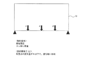
次に、ユーザは、例えばキーボードやマウス等を操作して、境界条件を設定する。境界条件は、例えば、荷重条件、拘束条件、接触条件等からなり、リブを設計しようとする物品によって設定される条件は異なる。さらに、ユーザは、制約条件と目的関数とを入力する。制約条件と目的関数は、先に入力した境界条件に対応して決定されるものである。本例においては、制約条件は、物品の長辺の「両端固定、かつ、3か所に荷重」と設定され、目的関数Σ(x)は、「荷重点の変位量がA(特定の値)以下であり、最も軽い形状」と設定されるものとする。
The
Next, the user sets a boundary condition by operating, for example, a keyboard and a mouse. The boundary condition includes, for example, a load condition, a constraint condition, a contact condition, and the like. Further, the user inputs a constraint condition and an objective function. The constraint condition and the objective function are determined in accordance with the boundary condition input previously. In this example, the constraint condition is set as “fixed at both ends and load at three locations” on the long side of the article, and the objective function Σ (x) ) The following, the lightest shape "shall be set.
そして、以上のように設定されたシェルモデル10の2.5次元情報や、制約条件および目的関数を満たすように、物品の3次元データに対してトポロジー最適化処理が実行される。この処理は、例えば、非特許文献1に示されるアルテアエンジニアリング社の「OptiStruct」に代表される設計支援ソフトをリブ設計装置にインストールして実行させることが可能である。なお、本例では、トポロジー最適化の手法として、密度法を用いる場合について説明する。
Then, the topology optimization process is executed on the three-dimensional data of the article so as to satisfy the 2.5-dimensional information of the
トポロジー最適化処理の結果は、シェルモデル10の要素ごとの密度を示す密度分布情報として表示装置に表示される。図2(a)は、表示装置に表示された密度分布情報の一例を示す図である。本例においては、密度の高い要素をより濃い色で表している。すなわち、本例においては、密度の高い要素が鉄橋のような形状11をなしている。この形状11の領域が、トポロジー最適化処理によってリブを形成すべき箇所であると判断された領域である。
The result of the topology optimization process is displayed on the display device as density distribution information indicating the density of each element of the
その後、図2(b)に示されるように、ユーザは密度の高い要素部分(形状11)をマウス等で選択し、最終的なリブ形状12を決定する。
なお、トポロジー最適化の処理結果である密度分布情報(図2(a))は、制約条件や目的関数の設定によって変化する。よって、密度分布情報において、例えばシェルモデル10の全体(全要素)に渡って密度が高くなってしまうような場合には、制約条件や目的条件を設定しなおして、再度、設計支援ソフトウェアにトポロジー最適化処理を実行させる。
Thereafter, as shown in FIG. 2B, the user selects a high-density element portion (shape 11) with a mouse or the like, and determines the
It should be noted that the density distribution information (FIG. 2A), which is the topology optimization processing result, varies depending on the constraint conditions and the objective function settings. Therefore, in the density distribution information, for example, when the density becomes high over the whole shell model 10 (all elements), the constraint conditions and objective conditions are reset, and the topology is again sent to the design support software. Run the optimization process.
(リブ設計装置の構成)
図3は、本実施形態に係るリブ設計方法を実行するリブ設計装置の構成例を示す図である。図3に示されるリブ設計装置1は、形状データ取得部100と、シェル情報取得部110と、シェル分割部120と、境界条件取得部130と、最適化条件取得部140と、最適化処理部150と、リブ生成部160と、を有する。
(Rib design device configuration)
FIG. 3 is a diagram illustrating a configuration example of a rib designing apparatus that executes the rib designing method according to the present embodiment. The rib design apparatus 1 shown in FIG. 3 includes a shape
形状データ取得部100は、リブを設計する物品の形状を示す3次元形状データを取得する。3次元形状データの取得の方法は様々にありうる。例えば、CD−ROM等の記録媒体からの入力を受け付ける。
シェル情報取得部110は、リブを設計する物品の形状の少なくとも一部を含み物品の形状の変形が許容される空間である設計空間内において、リブを設ける前記物品の略面形状部分に対して設定される面状のシェルモデル(2.5次元情報)を取得する。
The shape
The shell
シェル分割部120は、シェル情報取得部110で取得された面状のシェルモデルをメッシュ状の複数の要素(エレメント)に分割する。
境界条件取得部130は、物品が使用される際の使用条件を示す境界条件を取得する。
最適化条件取得部140は、境界条件取得部130で取得された物品の境界条件に対応した制約条件と、目的関数と、を含む最適化条件を取得する。目的関数は、例えば、物品の質量、体積、コンプライアンス、重心位置、回転慣性、変位、応力、ひずみ、要素力、複合材の応答(応力、ひずみ、破壊基準)、変位、速度、加速度、応力、要素力、固有値、座屈係数、等が挙げられる。本実施形態においては、非限定的一例として、目的関数が質量である場合について説明する。
The
The boundary
The optimization
最適化処理部150は、シェル分割部120において複数の要素に分割された面状のシェルモデルに対して、最適化条件取得部140において取得された最適化条件を満たすようにトポロジー最適化を行い、最適化処理後の最適形状を表す情報である最適形状情報を出力する。本実施形態のリブ設計方法においては、非限定的一例として、トポロジー最適化の手法として、密度法を採用し、最適形状情報として密度分布情報を出力する場合について説明する。ただし、これに限定されるものではない。トポロジー最適化の手法として、例えば、均質化設計法、グランドストラクチャー法、等を採用することも可能である。
The
リブ生成部160は、最適化処理部150によって出力された最適形状情報に対応するようにリブを生成する。このリブ生成部160の処理はリブ設計装置1によって自動的に実行されてもよいし、例えば、ユーザがリブ設計装置1の表示装置に表示される最適形状情報を視認して、マウス等の入力装置でリブを設計する部分を選択することによって、その要素部分に対応する物品の部分にリブが生成されるようになっていてもよい。
The
(処理フロー)
図4は、図3に示されるリブ設計装置1が実行するリブ設計処理手順の一例を示すフローチャートである。
リブ設計装置1のユーザは、リブを生成する前の物品の3次元形状データが記録されているCD−ROM等の記録媒体をリブ設計装置1に読み込ませる。形状データ取得部100は、この物品の3次元形状データの入力を受け付けることで、3次元形状データを取得する(ステップS101)。形状データ取得部100が入力を受け付けた3次元形状データは、一旦、RAMやハードディスク等の記憶装置に記憶された後、リブ設計装置1のディスプレイ等の表示装置に表示出力される。これにより、ユーザは物品の3次元形状を視認できる。なお、3次元形状データは、例えば、リブ設計装置1が接続されているネットワークを介して、他の装置から受信する等となっていてもよい。
(Processing flow)
Figure 4 is a flowchart showing an example of a rib design procedure ribs designing apparatus 1 illustrated in FIG. 3 is executed.
The user of the rib designing apparatus 1 causes the rib designing apparatus 1 to read a recording medium such as a CD-ROM on which the three-dimensional shape data of the article before generating the rib is recorded. The shape
また、CD−ROM等の記録媒体から3次元形状データを読み込む際、この3次元形状データには物品形状内の変更可能領域(形状変更が許容される領域)がすでに設定されている場合がある。もし、設定されていない場合には、表示装置に表示された物品の3次元形状に対して、ユーザがマウス等の入力装置を操作して変更可能領域を設定するようになっていてもよい。 In addition, when 3D shape data is read from a recording medium such as a CD-ROM, a changeable area (an area in which shape change is allowed) in the article shape may already be set in the 3D shape data. . If not set, the changeable area may be set by the user operating the input device such as a mouse for the three-dimensional shape of the article displayed on the display device.
次に、ユーザは、マウス等の入力装置を操作して、表示装置に表示された物品の3次元形状の設計空間内において、リブを設ける物品の略面形状部分に対してシェルを設定する。また、ユーザは、キーボード、マウス等の入力装置を操作して、シェルごとに2.5次元情報を入力する(ステップS102)。本実施形態においては、非限定的一例として、2.5次元情報は、シェルの範囲を示す2次元座標と、シェルの厚みを示す厚み情報とから構成されるものとする。また、ここで設定されるシェルの厚みは、そのシェルが対応している物品の略面形状部分に形成するリブの高さに対応する。 Next, the user operates an input device such as a mouse to set a shell for the substantially surface-shaped portion of the article on which the rib is provided in the three-dimensional design space of the article displayed on the display device. In addition, the user operates the input device such as a keyboard and a mouse to input 2.5-dimensional information for each shell (step S102). In the present embodiment, as a non-limiting example, the 2.5-dimensional information is configured from two-dimensional coordinates indicating the range of the shell and thickness information indicating the thickness of the shell. Further, the thickness of the shell set here corresponds to the height of the rib formed on the substantially surface-shaped portion of the article to which the shell corresponds.
また、本実施形態においては、非限定的一例として、一つのシェルに対して一意の厚みが設定されるものとする。すなわち、例えば、物品の一つの面において、場所によってシェルの厚み(リブの高さ)を異ならせたい場合には、シェルの厚みが異なる場所ごとにシェルを設定する。ただし、シェルの設定方法はこれに限定されるものではなく、一つのシェルにおいて場所によって異なる厚みを設定する(すなわち、不均一に厚みを設定する)ようになっていてもよい。
ここで、シェル情報取得部110は、上記のようにユーザが入力したシェルごとの2.5次元情報を受け付け、RAM等のメモリに記憶する。
シェル分割部120は、ステップS102で入力を受け付けたシェルモデルを複数の要素(エレメント)に分割する(ステップS103)。
In the present embodiment, as a non-limiting example, a unique thickness is set for one shell. That is, for example, when it is desired to change the thickness of the shell (the height of the rib) depending on the location on one surface of the article, the shell is set for each location where the thickness of the shell is different. However, the shell setting method is not limited to this, and a different thickness may be set depending on the location in one shell (that is, the thickness may be set non-uniformly).
Here, the shell
The
次に、ユーザはキーボード等の入力装置を操作して、荷重条件や拘束条件等の境界条件を入力する。ここで、境界条件には、例えば、荷重条件と拘束条件とが含まれる。「荷重条件」とは、例えば、物品のいずれの部位に、どの方向にどれくらいの力が加わるか等の条件を示すものである。また、「拘束条件」とは、例えば、物品において固定される部位、回転する際の回転軸もしくは回転中心の点等の物品を拘束する条件を示すものである。 Next, the user operates an input device such as a keyboard to input boundary conditions such as load conditions and constraint conditions. Here, the boundary condition includes, for example, a load condition and a constraint condition. The “load condition” indicates a condition such as how much force is applied in which direction to which part of the article. Further, the “restraint condition” indicates a condition for restraining the article such as a portion fixed in the article, a rotation axis at the time of rotation, or a point of the rotation center.
また、境界条件には、接触条件等が含まれる場合もある。「接触条件」とは、例えば、リブを設計する物品と他の物品とが接触する際の固定状態(接着されているのか接触しているのみであるのか)、接触時の強度等の条件を示すものである。
境界条件取得部130は、上記のようにして入力された境界条件を受け付け、RAM等の記憶装置に記憶する(ステップS104)。
Further, the boundary condition may include a contact condition or the like. “Contact condition” refers to, for example, conditions such as a fixed state (whether it is adhered or only in contact) when an article for which a rib is designed and another article are in contact with each other, strength at the time of contact, etc. It is shown.
The boundary
ユーザは、キーボード等の入力装置を操作して、境界条件に対応した制約条件や目的関数を入力する。最適化条件取得部140は、ユーザによって入力された制約条件と目的関数とを含む最適化条件を受け付け、RAM等の記憶装置に記憶する(ステップS105)。
最適化処理部150は、ステップS103で複数の要素に分割されたシェルモデルに対し、ステップS105で取得された最適化条件を満たすようにトポロジー最適化処理を実行する(ステップS106)。なお、これらの処理は、例えば、非特許文献1に示されるアルテアエンジニアリング社の「OptiStruct」に代表される設計支援ソフトによって実行させることが可能である。
The user operates a keyboard or other input device to input constraint conditions and objective functions corresponding to the boundary conditions. The optimization
The
そして、最適化処理部150は、トポロジー最適化処理の結果として、シェルモデルの複数の要素の各要素における密度を示す密度分布情報を表示装置等に出力する(ステップS107)。
ユーザは、表示装置に表示出力された密度分布情報を視認し、リブを設定する場所として、密度の高い要素部分をマウス等の入力装置で選択する。リブ生成部160は、ユーザが入力装置で選択した要素部分にリブが設置された状態の形状を示す3次元データをハードディスクやRAM等の記憶装置に記憶する(ステップS108)。
Then, as a result of the topology optimization process, the
The user visually recognizes the density distribution information displayed and output on the display device, and selects an element portion having a high density with an input device such as a mouse as a place for setting a rib. The
(リブ設計装置のハードウェア構成)
図5は、本実施形態に係るリブ設計装置のハードウェア構成の一例を示すブロック図である。図5に示されるコンピュータ装置であるリブ設計装置1において、CPU201は、ROM204またはハードディスクドライブ206に格納されたプログラムに従い、RAM205を一次記憶用ワークメモリとして利用して、システム全体を制御する。
これにより、上記説明した本実施形態に係るリブ設計装置における形状データ取得部100、シェル情報取得部110、シェル分割部120、境界条件取得部130、最適化条件取得部140、最適化処理部150、およびリブ生成部160における機能が実現される。すなわち、CPU201は、マウス202aまたはキーボード202を介して入力されるデータをRAM205やハードディスクドライブ206等に記憶し、またこれらのデータを用いて、ハードディスクドライブ206に格納されたプログラムを読み出して、本実施形態のリブ設計処理を実行する。
(Hardware configuration of rib design equipment)
FIG. 5 is a block diagram illustrating an example of a hardware configuration of the rib designing apparatus according to the present embodiment. In the rib designing apparatus 1 which is a computer apparatus shown in FIG. 5, the
Accordingly, the shape
ディスプレイインタフェイス203には、LCDなどの表示装置が接続され、CPU201が実行するリブ設計処理に必要なデータ(シェルモデルの2.5次元情報、境界条件、最適化条件等のデータ)のユーザ入力用画面、処理経過表示画面、トポロジー最適化の処理結果である密度分布情報等が表示装置に表示される。
リムーバブルメディアドライブ207は、主に、リムーバブルメディアからハードディスクドライブ206へファイルを書き込んだり、ハードディスクドライブ206から読み出したファイルをリムーバブルメディアへ書き込む場合に利用される。リムーバブルメディアとしては、フロッピディスク(FD)、CD−ROM、CD−R、CD−R/W、DVD−ROM、DVD−R、DVD−R/W、DVD−RAM、MO、ブルーレイディスク(BD)、メモリカード、CFカード、スマートメディア、SDカード、メモリスティックなどが利用可能である。
A display device such as an LCD is connected to the
The removable media drive 207 is mainly used when writing a file from the removable medium to the
プリンタインタフェイス208には、レーザビームプリンタやインクジェットプリンタなどのプリンタが接続される。
ネットワークインタフェイス209は、コンピュータ装置であるリブ設計装置1を外部のネットワークへ接続するためのインタフェイスである。例えば、リブ設計装置1は、ネットワークインタフェイス209を介して、物品の3次元形状データを受信してハードディスクドライブ206等に記憶するようになっていてもよい。また、ネットワークインタフェイス209を介して、リブ設計処理の処理結果である最適化形状のデータを外部の装置等に出力するようになっていてもよい。
A printer such as a laser beam printer or an ink jet printer is connected to the
The
図5に示した本実施形態に係るリブ設計装置のハードウェア構成は一例に過ぎず、その他の任意のハードウェア構成を用いることが可能である。
なお、本発明の範囲は、図示され記載された例示的な実施形態に限定されるものではなく、本発明が目的とするものと均等な効果をもたらすすべての実施形態をも含む。さらに、本発明の範囲は、すべての開示されたそれぞれの特徴のうち特定の特徴のあらゆる所望する組み合わせによって画されうる。
The hardware configuration of the rib designing apparatus according to the present embodiment shown in FIG. 5 is merely an example, and any other hardware configuration can be used.
It should be noted that the scope of the present invention is not limited to the illustrated and described exemplary embodiments, but includes all embodiments that provide the same effects as those intended by the present invention. Further, the scope of the invention can be defined by any desired combination of particular features among all the disclosed features.
1 リブ設計装置
10 シェルモデル
11 鉄橋形状(密度の高い要素部分)
12 リブ形状
100 形状データ取得部
110 シェル情報取得部
120 シェル分割部
130 境界条件取得部
140 最適化条件取得部
150 最適化処理部
160 リブ生成部
201 CPU
202 キーボード
202a マウス
203 ディスプレイインタフェイス
204 ROM
205 RAM
206 ハードディスクドライブ
207 リムーバブルメディアドライブ
208 プリンタインタフェイス
209 ネットワークインタフェイス
1
DESCRIPTION OF
202
205 RAM
206
Claims (3)
前記形状データ取得部が、前記物品の形状を示す3次元形状データを取得する第1のステップと、
前記シェル情報取得部が、前記物品の形状の少なくとも一部を含む空間モデルを設計し、当該空間モデル内において、リブを設ける前記物品の略面形状部分に対して設定される、シェルの範囲を示す2次元座標と前記シェルの厚みを示す厚み情報とからなる2.5次元情報の面状のシェルモデルを取得する第2のステップと、
前記シェル分割部が、前記シェルモデルをメッシュ状の複数の要素に分割する第3のステップと、
前記境界条件取得部が、前記物品が使用される際の使用条件を示す境界条件を取得する第4のステップと、
前記最適化条件取得部が、前記境界条件に対応した制約条件と、目的関数と、を含む最適化条件を取得する第5のステップと、
前記最適化処理部が、前記第3のステップにおいて前記メッシュ状の複数の要素に分割された前記シェルモデルに対して、前記最適化条件取得部で取得された前記最適化条件を満たすようにトポロジー最適化処理を行い、最適化処理後の最適形状を表す情報の密度分布情報である最適形状情報を出力する第6のステップと、
前記リブ生成部が、前記最適形状情報に対応するようにリブを生成する第7のステップと、
を含むことを特徴とするリブ設計方法。 A shape data acquisition unit for acquiring three-dimensional shape data of an article, a shell information acquisition unit connected to the shape data acquisition unit, a shell division unit connected to the shell information acquisition unit, and a boundary of the article and boundary condition acquisition unit for acquiring condition, and optimization condition acquisition unit connected to the boundary condition acquisition unit, and optimization processing unit connected to the said shell dividing portion and the optimization condition acquisition unit, wherein A rib design method that is executed by a rib design device having a rib generation unit connected to an optimization processing unit and performs a topology optimization process to design a rib of an article,
A first step in which the shape data acquisition unit acquires three-dimensional shape data indicating the shape of the article;
The shell information acquisition unit designs a space model including at least a part of the shape of the article , and the range of the shell that is set for the substantially surface shape portion of the article in which the rib is provided in the space model. A second step of acquiring a planar shell model of 2.5-dimensional information comprising two-dimensional coordinates to be indicated and thickness information indicating the thickness of the shell;
A third step in which the shell dividing unit divides the shell model into a plurality of mesh-shaped elements;
A fourth step in which the boundary condition acquisition unit acquires a boundary condition indicating a use condition when the article is used ;
A fifth step in which the optimization condition acquisition unit acquires an optimization condition including a constraint condition corresponding to the boundary condition and an objective function;
The topology is so that the optimization processing unit satisfies the optimization condition acquired by the optimization condition acquisition unit with respect to the shell model divided into the plurality of mesh-like elements in the third step. A sixth step of performing optimization processing and outputting optimal shape information which is density distribution information of information representing the optimal shape after the optimization processing;
A seventh step in which the rib generator generates a rib so as to correspond to the optimum shape information ;
The rib design method characterized by including.
前記物品の形状を示す3次元形状データを取得する形状データ取得部と、
前記形状データ取得部で取得された前記3次元形状データである前記物品の形状の少なくとも一部を含む空間モデルを設計し、当該空間モデル内において、前記リブを設ける前記物品の略面形状部分に対して設定される、シェルの範囲を示す2次元座標と前記シェルの厚みを示す厚み情報とからなる2.5次元情報の面状のシェルモデルを取得するシェル情報取得部と、
前記シェル情報取得部で取得された前記シェルモデルをメッシュ状の複数の要素に分割するシェル分割部と、
前記物品が使用される際の使用条件を示す境界条件を取得する境界条件取得部と、
前記境界条件取得部で取得された前記境界条件に対応した制約条件と、目的関数と、を含む最適化条件を取得する最適化条件取得部と、
前記シェル分割部において前記メッシュ状の複数の要素に分割された前記シェルモデルに対して、前記最適化条件取得部で取得された前記最適化条件を満たすようにトポロジー最適化処理を行い、最適化処理後の最適形状を表す情報の密度分布情報である最適形状情報を出力する最適化処理部と、
前記最適化処理部で出力された前記最適形状情報に対応するようにリブを生成するリブ生成部と、
を有することを特徴とするリブ設計装置。 A rib design device for designing a rib of an article by performing a topology optimization process,
A shape data acquisition unit for acquiring three-dimensional shape data indicating the shape of the article;
The design shape data space model including at least a portion of the shape of the article is obtained the three-dimensional shape data in a capture unit, within the space model, a substantially plane-shaped portion of the article providing the ribs A shell information acquisition unit configured to acquire a planar shell model of 2.5D information including two-dimensional coordinates indicating the range of the shell and thickness information indicating the thickness of the shell,
A shell dividing unit that divides the shell model acquired by the shell information acquiring unit into a plurality of mesh-shaped elements;
A boundary condition acquisition unit for acquiring a boundary condition indicating a use condition when the article is used ;
An optimization condition acquisition unit that acquires an optimization condition including a constraint condition corresponding to the boundary condition acquired by the boundary condition acquisition unit and an objective function;
A topology optimization process is performed on the shell model divided into the mesh-like elements in the shell division unit so as to satisfy the optimization condition acquired by the optimization condition acquisition unit, and the optimization is performed. An optimization processing unit that outputs optimum shape information that is density distribution information of information representing the optimum shape after processing;
A rib generating unit that generates ribs so as to correspond to the optimal shape information output by the optimization processing unit ;
A rib designing apparatus comprising:
前記コンピュータに、
前記物品の形状を示す3次元形状データを取得する第1の処理ステップと、
前記物品の形状の少なくとも一部を含む空間モデルを設計し、当該空間モデル内において、リブを設ける前記物品の略面形状部分に対して設定される、シェルの範囲を示す2次元座標と前記シェルの厚みを示す厚み情報とからなる2.5次元情報の面状のシェルモデルを取得する第2の処理ステップと、
前記シェルモデルをメッシュ状の複数の要素に分割する第3の処理ステップと、
前記物品が使用される際の使用条件を示す境界条件を取得する第4の処理ステップと、
前記境界条件に対応した制約条件と、目的関数と、を含む最適化条件を取得する第5の処理ステップと、
前記第3の処理ステップにおいて前記メッシュ状の複数の要素に分割された前記シェルモデルに対して、前記最適化条件を満たすようにトポロジー最適化処理を行い、最適化処理後の最適形状を表す情報の密度分布情報である最適形状情報を出力する第6の処理ステップと、
前記最適形状情報に対応するようにリブを生成する第7の処理ステップと、
を実行させるプログラムであるリブ設計プログラム。 A rib design program for causing a computer to execute a rib design process for designing a rib of an article by performing a topology optimization process,
In the computer,
A first processing step of acquiring three-dimensional shape data indicating the shape of the article;
A space model including at least a part of the shape of the article is designed, and in the space model, two-dimensional coordinates indicating a range of a shell set for a substantially surface shape portion of the article provided with a rib and the shell A second processing step for obtaining a planar shell model of 2.5D information comprising thickness information indicating the thickness of
A third processing step of dividing the shell model into a plurality of mesh-shaped elements;
A fourth processing step for obtaining a boundary condition indicating a use condition when the article is used ;
A fifth processing step for obtaining an optimization condition including a constraint condition corresponding to the boundary condition and an objective function;
Information representing the optimum shape after the optimization process by performing a topology optimization process so as to satisfy the optimization condition for the shell model divided into the mesh-like elements in the third process step A sixth processing step of outputting optimum shape information which is density distribution information of
A seventh processing step for generating a rib to correspond to the optimum shape information ;
Rib design program that is a program that executes
Priority Applications (1)
| Application Number | Priority Date | Filing Date | Title |
|---|---|---|---|
| JP2011260228A JP5977020B2 (en) | 2011-11-29 | 2011-11-29 | Rib design method, rib design apparatus, and rib design program |
Applications Claiming Priority (1)
| Application Number | Priority Date | Filing Date | Title |
|---|---|---|---|
| JP2011260228A JP5977020B2 (en) | 2011-11-29 | 2011-11-29 | Rib design method, rib design apparatus, and rib design program |
Publications (3)
| Publication Number | Publication Date |
|---|---|
| JP2013114464A JP2013114464A (en) | 2013-06-10 |
| JP2013114464A5 JP2013114464A5 (en) | 2015-01-22 |
| JP5977020B2 true JP5977020B2 (en) | 2016-08-24 |
Family
ID=48709956
Family Applications (1)
| Application Number | Title | Priority Date | Filing Date |
|---|---|---|---|
| JP2011260228A Active JP5977020B2 (en) | 2011-11-29 | 2011-11-29 | Rib design method, rib design apparatus, and rib design program |
Country Status (1)
| Country | Link |
|---|---|
| JP (1) | JP5977020B2 (en) |
Cited By (1)
| Publication number | Priority date | Publication date | Assignee | Title |
|---|---|---|---|---|
| CN110188498B (en) * | 2019-06-05 | 2022-01-04 | 哈尔滨理工大学 | Optimal non-design space partitioning method based on topological optimization variable density method |
Families Citing this family (4)
| Publication number | Priority date | Publication date | Assignee | Title |
|---|---|---|---|---|
| CN103401248B (en) * | 2013-07-17 | 2015-12-02 | 华南理工大学 | A kind of containing wind energy turbine set power distribution network random reactive optimization method for power |
| EP3502931B1 (en) * | 2017-12-24 | 2023-03-15 | Dassault Systèmes | Designing a part by topology optimization |
| CN111325854B (en) * | 2018-12-17 | 2023-10-24 | 三菱重工业株式会社 | Shape model correction device, shape model correction method, and storage medium |
| CN111256093A (en) * | 2020-01-17 | 2020-06-09 | 中节能晶和照明有限公司 | High IK-level lamp housing and design method thereof |
Family Cites Families (8)
| Publication number | Priority date | Publication date | Assignee | Title |
|---|---|---|---|---|
| JP3025062B2 (en) * | 1991-07-12 | 2000-03-27 | 積水化学工業株式会社 | Optimization design system for thin plate products |
| US6473724B1 (en) * | 1999-05-10 | 2002-10-29 | Ford Global Technologies, Inc. | Method of designing embossed ribs in plates |
| JP2001297118A (en) * | 2000-04-14 | 2001-10-26 | Hitachi Ltd | Method and device for optimizing structure |
| JP4364499B2 (en) * | 2002-11-06 | 2009-11-18 | 富士重工業株式会社 | Rib optimization method and recording medium |
| JP2006350720A (en) * | 2005-06-16 | 2006-12-28 | Ntn Corp | Shape design method for bracket of automatic tensioner |
| JP2007188164A (en) * | 2006-01-11 | 2007-07-26 | Vanderplaats Design Optimization Consulting Inc | Acoustic structure compound optimal design analysis method and its optimal design system and its analysis program and recording medium with its analysis program recorded |
| JP2009122999A (en) * | 2007-11-15 | 2009-06-04 | Hitachi Ltd | Three-dimensional shape optimization apparatus and three-dimensional shape optimization method |
| JP5236516B2 (en) * | 2009-01-30 | 2013-07-17 | アイシン・エィ・ダブリュ株式会社 | Acoustic characteristic optimization model analysis apparatus, acoustic characteristic optimization model analysis method, and acoustic characteristic optimization model analysis program |
-
2011
- 2011-11-29 JP JP2011260228A patent/JP5977020B2/en active Active
Cited By (1)
| Publication number | Priority date | Publication date | Assignee | Title |
|---|---|---|---|---|
| CN110188498B (en) * | 2019-06-05 | 2022-01-04 | 哈尔滨理工大学 | Optimal non-design space partitioning method based on topological optimization variable density method |
Also Published As
| Publication number | Publication date |
|---|---|
| JP2013114464A (en) | 2013-06-10 |
Similar Documents
| Publication | Publication Date | Title |
|---|---|---|
| JP5977020B2 (en) | Rib design method, rib design apparatus, and rib design program | |
| EP3502931B1 (en) | Designing a part by topology optimization | |
| JP5236516B2 (en) | Acoustic characteristic optimization model analysis apparatus, acoustic characteristic optimization model analysis method, and acoustic characteristic optimization model analysis program | |
| KR101628644B1 (en) | Analyzing method and apparatus for optimizing welding position of structure | |
| US20160263836A1 (en) | Three-dimensional object forming system | |
| CN108268222A (en) | For the pattern of 3D printing | |
| JP2013025593A (en) | Optimization analysis method and device for junction position of structure | |
| JP5378171B2 (en) | Optimization model analysis apparatus, optimization model analysis method, and optimization model analysis program | |
| JP5141050B2 (en) | Design method and program | |
| EP4163812A1 (en) | Designing a modeled object | |
| JP4809683B2 (en) | Analysis model generation apparatus, analysis model generation method, and analysis model generation program | |
| JP6520459B2 (en) | Forging die design support apparatus and forging die design support method | |
| JP5056079B2 (en) | Design method and program | |
| JP5343052B2 (en) | Structure analysis method, program, and analysis apparatus | |
| JP5240031B2 (en) | Stiffening method for structures | |
| JP2005081417A (en) | Initial shape preparing device for model of press simulation, press simulation device, initial shape preparing method of model of press simulation, and simulation method | |
| JP4744541B2 (en) | Design support device | |
| JPWO2008149623A1 (en) | Simplified analysis model of finite element method | |
| JP6323410B2 (en) | Structure partial analysis model generation apparatus and method, and structure collision analysis method using partial analysis model generated by structure partial analysis model generation method | |
| US20210027534A1 (en) | Information processing apparatus and non-transitory computer readable medium | |
| JP4783684B2 (en) | A drawn product model creation system, a drawn product model analysis system provided with the same, a drawn product model creation program, and a drawn product analysis program provided therewith. | |
| JP4780908B2 (en) | Surface quality prediction apparatus and surface quality prediction program | |
| JP4665888B2 (en) | CAD data conversion apparatus and method | |
| JP5962057B2 (en) | 3D shape creation support program, method and apparatus | |
| WO2022080091A1 (en) | Design assistance device, design assistance method, design assistance program, metamaterial information generation method, structure, and structure manufacturing method |
Legal Events
| Date | Code | Title | Description |
|---|---|---|---|
| A521 | Written amendment |
Free format text: JAPANESE INTERMEDIATE CODE: A523 Effective date: 20141127 |
|
| A621 | Written request for application examination |
Free format text: JAPANESE INTERMEDIATE CODE: A621 Effective date: 20141127 |
|
| A977 | Report on retrieval |
Free format text: JAPANESE INTERMEDIATE CODE: A971007 Effective date: 20151215 |
|
| A131 | Notification of reasons for refusal |
Free format text: JAPANESE INTERMEDIATE CODE: A131 Effective date: 20151222 |
|
| A521 | Written amendment |
Free format text: JAPANESE INTERMEDIATE CODE: A523 Effective date: 20160218 |
|
| A711 | Notification of change in applicant |
Free format text: JAPANESE INTERMEDIATE CODE: A712 Effective date: 20160401 |
|
| A521 | Written amendment |
Free format text: JAPANESE INTERMEDIATE CODE: A523 Effective date: 20160419 |
|
| TRDD | Decision of grant or rejection written | ||
| A01 | Written decision to grant a patent or to grant a registration (utility model) |
Free format text: JAPANESE INTERMEDIATE CODE: A01 Effective date: 20160628 |
|
| A61 | First payment of annual fees (during grant procedure) |
Free format text: JAPANESE INTERMEDIATE CODE: A61 Effective date: 20160721 |
|
| R150 | Certificate of patent or registration of utility model |
Ref document number: 5977020 Country of ref document: JP Free format text: JAPANESE INTERMEDIATE CODE: R150 |
|
| S531 | Written request for registration of change of domicile |
Free format text: JAPANESE INTERMEDIATE CODE: R313531 |
|
| R350 | Written notification of registration of transfer |
Free format text: JAPANESE INTERMEDIATE CODE: R350 |