EP4451015A1 - Messverfahren und -vorrichtung für ein globales navigationssatellitensystem (gnss) - Google Patents
Messverfahren und -vorrichtung für ein globales navigationssatellitensystem (gnss) Download PDFInfo
- Publication number
- EP4451015A1 EP4451015A1 EP21967788.7A EP21967788A EP4451015A1 EP 4451015 A1 EP4451015 A1 EP 4451015A1 EP 21967788 A EP21967788 A EP 21967788A EP 4451015 A1 EP4451015 A1 EP 4451015A1
- Authority
- EP
- European Patent Office
- Prior art keywords
- terminal
- gnss
- measurement
- position information
- network device
- Prior art date
- Legal status (The legal status is an assumption and is not a legal conclusion. Google has not performed a legal analysis and makes no representation as to the accuracy of the status listed.)
- Pending
Links
Images


Classifications
-
- H—ELECTRICITY
- H04—ELECTRIC COMMUNICATION TECHNIQUE
- H04W—WIRELESS COMMUNICATION NETWORKS
- H04W56/00—Synchronisation arrangements
- H04W56/004—Synchronisation arrangements compensating for timing error of reception due to propagation delay
- H04W56/0045—Synchronisation arrangements compensating for timing error of reception due to propagation delay compensating for timing error by altering transmission time
-
- G—PHYSICS
- G01—MEASURING; TESTING
- G01S—RADIO DIRECTION-FINDING; RADIO NAVIGATION; DETERMINING DISTANCE OR VELOCITY BY USE OF RADIO WAVES; LOCATING OR PRESENCE-DETECTING BY USE OF THE REFLECTION OR RERADIATION OF RADIO WAVES; ANALOGOUS ARRANGEMENTS USING OTHER WAVES
- G01S19/00—Satellite radio beacon positioning systems; Determining position, velocity or attitude using signals transmitted by such systems
- G01S19/01—Satellite radio beacon positioning systems transmitting time-stamped messages, e.g. GPS [Global Positioning System], GLONASS [Global Orbiting Navigation Satellite System] or GALILEO
- G01S19/13—Receivers
- G01S19/21—Interference related issues ; Issues related to cross-correlation, spoofing or other methods of denial of service
-
- G—PHYSICS
- G01—MEASURING; TESTING
- G01S—RADIO DIRECTION-FINDING; RADIO NAVIGATION; DETERMINING DISTANCE OR VELOCITY BY USE OF RADIO WAVES; LOCATING OR PRESENCE-DETECTING BY USE OF THE REFLECTION OR RERADIATION OF RADIO WAVES; ANALOGOUS ARRANGEMENTS USING OTHER WAVES
- G01S19/00—Satellite radio beacon positioning systems; Determining position, velocity or attitude using signals transmitted by such systems
- G01S19/01—Satellite radio beacon positioning systems transmitting time-stamped messages, e.g. GPS [Global Positioning System], GLONASS [Global Orbiting Navigation Satellite System] or GALILEO
- G01S19/13—Receivers
- G01S19/34—Power consumption
-
- H—ELECTRICITY
- H04—ELECTRIC COMMUNICATION TECHNIQUE
- H04W—WIRELESS COMMUNICATION NETWORKS
- H04W64/00—Locating users or terminals or network equipment for network management purposes, e.g. mobility management
-
- H—ELECTRICITY
- H04—ELECTRIC COMMUNICATION TECHNIQUE
- H04W—WIRELESS COMMUNICATION NETWORKS
- H04W64/00—Locating users or terminals or network equipment for network management purposes, e.g. mobility management
- H04W64/006—Locating users or terminals or network equipment for network management purposes, e.g. mobility management with additional information processing, e.g. for direction or speed determination
-
- G—PHYSICS
- G01—MEASURING; TESTING
- G01S—RADIO DIRECTION-FINDING; RADIO NAVIGATION; DETERMINING DISTANCE OR VELOCITY BY USE OF RADIO WAVES; LOCATING OR PRESENCE-DETECTING BY USE OF THE REFLECTION OR RERADIATION OF RADIO WAVES; ANALOGOUS ARRANGEMENTS USING OTHER WAVES
- G01S19/00—Satellite radio beacon positioning systems; Determining position, velocity or attitude using signals transmitted by such systems
- G01S19/01—Satellite radio beacon positioning systems transmitting time-stamped messages, e.g. GPS [Global Positioning System], GLONASS [Global Orbiting Navigation Satellite System] or GALILEO
- G01S19/13—Receivers
- G01S19/14—Receivers specially adapted for specific applications
-
- H—ELECTRICITY
- H04—ELECTRIC COMMUNICATION TECHNIQUE
- H04B—TRANSMISSION
- H04B7/00—Radio transmission systems, i.e. using radiation field
- H04B7/14—Relay systems
- H04B7/15—Active relay systems
- H04B7/185—Space-based or airborne stations; Stations for satellite systems
- H04B7/1851—Systems using a satellite or space-based relay
- H04B7/18513—Transmission in a satellite or space-based system
-
- H—ELECTRICITY
- H04—ELECTRIC COMMUNICATION TECHNIQUE
- H04W—WIRELESS COMMUNICATION NETWORKS
- H04W76/00—Connection management
- H04W76/20—Manipulation of established connections
- H04W76/27—Transitions between radio resource control [RRC] states
Definitions
- the disclosure relates to a field of wireless communication technology, in particular to a global navigation satellite system (GNSS) measurement method and apparatus.
- GNSS global navigation satellite system
- GNSS global navigation satellite system
- Embodiments of the disclosure provide a global navigation satellite system (GNSS) measurement method and apparatus, to ensure that a terminal can obtain GNSS position information in a timely and effective manner by performing a GNSS measurement when the terminal is in a connected state, thereby avoiding uplink transmission interference between different terminals.
- GNSS global navigation satellite system
- a GNSS measurement method applied to a terminal, includes: performing a GNSS measurement in a connected state in response to expiration of current GNSS position information of the terminal.
- the GNSS measurement is performed when the terminal is in the connected state, thereby avoiding uplink transmission interference between different terminals.
- a GNSS measurement method applied to a network device, includes: determining that current GNSS position information of a terminal has expired, and causing the terminal to maintain in a connected state and to perform a GNSS measurement.
- the terminal is caused to maintain in the connected state and to perform the GNSS measurement, thereby avoiding uplink transmission interference between different terminals.
- a communication apparatus has an ability to implement part or all of the functions of the terminal in the method described in the first aspect.
- the communication apparatus may have functions of some or all of the embodiments of the disclosure, or may have a function of independently implementing any embodiment of the disclosure.
- the functions can be implemented by hardware, or can be implemented by executing corresponding software using the hardware.
- the hardware or software includes one or more units or modules corresponding to the above functions.
- the communication apparatus includes: a transceiver module and a processing module.
- the processing module is configured to support the communication apparatus to perform corresponding functions in the above method.
- the transceiver module is configured to support communication between the communication apparatus and other devices.
- the communication apparatus may further include a storage module, coupled to the transceiver module and the processing module, and configured to store necessary computer programs and data for the communication apparatus.
- the processing module may be a processor.
- the transceiver module may be a transceiver or a communication interface.
- the storage module may be a memory.
- a communication apparatus has an ability to implement part or all of the functions of the network device in the method described in the second aspect.
- the communication apparatus may have functions of some or all of the embodiments of the disclosure, or may have a function of independently implementing any embodiment of the disclosure.
- the functions can be implemented by hardware, or can be implemented by executing corresponding software using the hardware.
- the hardware or software includes one or more units or modules corresponding to the above functions.
- the communication apparatus includes: a transceiver module and a processing module.
- the processing module is configured to support the communication apparatus to perform corresponding functions in the above method.
- the transceiver module is configured to support communication between the communication apparatus and other devices.
- the communication apparatus may further include a storage module, coupled to the transceiver module and the processing module, and configured to store necessary computer programs and data for the communication apparatus.
- the processing module may be a processor.
- the transceiver module may be a transceiver or a communication interface.
- the storage module may be a memory.
- a communicating apparatus includes: a processor.
- the processor calls a computer program stored in a memory, the method described in the first aspect above is implemented.
- a communicating apparatus includes: a processor.
- the processor calls a computer program stored in a memory, the method described in the second aspect above is implemented.
- a communication apparatus includes: a processor, and a memory having a computer program stored thereon.
- the processor executes the computer program stored in the memory, to cause the communication apparatus to implement the method described in the first aspect above.
- a communication apparatus includes: a processor, and a memory having a computer program stored thereon.
- the processor executes the computer program stored in the memory, to cause the communication apparatus to implement the method described in the second aspect above.
- a communication apparatus includes: a processor and an interface circuit.
- the interface circuit is configured to receive code instructions and transmit them to the processor.
- the processor is configured to run the code instructions to cause the communication apparatus to perform the method described in the first aspect above.
- a communication apparatus includes: a processor and an interface circuit.
- the interface circuit is configured to receive code instructions and transmit them to the processor.
- the processor is configured to run the code instructions to cause the communication apparatus to perform the method described in the second aspect above.
- a communication system includes the communication apparatus of the third aspect and the communication apparatus of the fourth aspect; or the system includes the communication apparatus of the fifth aspect and the communication apparatus of the sixth aspect; or the system includes the communication apparatus of the seventh aspect and the communication apparatus of the eighth aspect; or the system includes the communication apparatus of the ninth aspect and the communication apparatus of the tenth aspect.
- a computer-readable storage medium configured to store instructions used by the above terminal. When the instructions are executed, the terminal is caused to implement the method of the first aspect.
- a computer-readable storage medium configured to store instructions used by the above network device. When the instructions are executed, the network device is caused to implement the method of the second aspect.
- a computer program product including a computer program is provided.
- the computer program is run by a computer, the computer is caused to implement the method of the first aspect.
- a computer program product including a computer program is provided.
- the computer program is run by a computer, the computer is caused to implement the method of the second aspect.
- a chip system includes at least one processor and an interface for supporting the terminal in realizing the functions involved in the first aspect, e.g., at least one of determining or processing data or information involved in the method described above.
- the chip system further includes a memory.
- the memory is configured to store necessary computer programs and data of the terminal.
- the chip system may consist of chips or may include a chip and other discrete devices.
- a chip system includes at least one processor and an interface for supporting the network device in realizing the functions involved in the second aspect, e.g., at least one of determining or processing data or information involved in the method described above.
- the chip system further includes a memory.
- the memory is configured to store necessary computer programs and data of the network device.
- the chip system may consist of chips or may include a chip and other discrete devices.
- a computer program is provided.
- the computer program is running on a computer, the computer is caused to implement the method of the first aspect.
- a computer program is provided.
- the computer program is running on a computer, the computer is caused to implement the method of the second aspect.
- GNSS Global navigation satellite system
- GNSS is a space-based radio navigation and positioning system that can provide a user with all-weather 3D coordinates, speed and time information anywhere on the Earth's surface or in near-Earth space.
- GNSS can use a group of observation parameters, such as satellite pseudoranges, ephemeris, satellite launch time and other parameters, as well as user clock differentials, to locate the user's terminal.
- Radio resource control (RRC)
- RRC carries out wireless resource management, control and scheduling through certain strategies and means to make full use of the limited wireless network resources in order to reach the planned coverage area while meeting the service quality requirements, thereby improving service capacity and resource utilization.
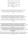
- FIG. 1 is a schematic diagram illustrating a communication system according to an embodiment of the disclosure.
- the communication system may include, but is not limited to, a network device and a terminal.
- the number and the form of devices illustrated in FIG. 1 are only for examples and do not constitute a limitation on the embodiments of the disclosure, and two or more network devices and two or more terminals may be included in practical applications.
- the communication system illustrated in FIG. 1 includes, for example, one network device 101 and one terminal 102.
- LTE long term evolution
- 5G 5th generation
- NR 5G new radio
- the network device 101 in embodiments of the disclosure is an entity on a network side for transmitting or receiving signals.
- the network device 101 may be an evolved NodeB (eNB), a transmission reception point (TRP), a next generation NodeB (gNB) in a NR system, a base station in other future mobile communication systems, or an access node in a Wi-Fi TM system.
- eNB evolved NodeB
- TRP transmission reception point
- gNB next generation NodeB
- the specific technology and specific device form adopted by the network device are not limited in the embodiments of the disclosure.
- the network device according to embodiments of the disclosure may be composed of a central unit (CU) and a distributed unit (DU).
- the CU may also be called control unit.
- CU-DU structure allows to divide a protocol layer of the network device, such as a base station, such that some functions of the protocol layer are placed in the CU for centralized control, and remaining some or all functions of the protocol layer are distributed in the DU, and the DU is centrally controlled by the CU.
- the terminal 102 in the embodiments of the disclosure is an entity on a user side for receiving or transmitting signals, such as a cellular phone.
- the terminal may also be referred to as terminal, user equipment (UE), mobile station (MS), mobile terminal (MT), and the like.
- the terminal can be a car with communication functions, a smart car, a mobile phone, an Internet of Things (IoT) device (e.g., NB-IoT or (e) machine type communication (MTC)), a wearable device, a Pad, a computer with wireless transceiver functions, a virtual reality (VR) terminal, an augmented reality (AR) terminal, a wireless terminal in industrial control, a wireless terminal in self-driving, a wireless terminal in remote medical surgery, a wireless terminal in smart grid, a wireless terminal in transportation safety, a wireless terminal in smart city, a wireless terminal in smart home, etc.
- IoT Internet of Things
- MTC machine type communication
- MTC machine type communication
- Pad a computer with wireless transceiver functions
- VR virtual reality
- AR augmented reality
- a wireless terminal in industrial control a wireless terminal in self-driving
- a wireless terminal in remote medical surgery a wireless terminal in smart grid, a wireless terminal in transportation safety, a wireless terminal in smart city
- FIG. 2 is a flowchart of a GNSS measurement method of an embodiment of the disclosure. The method is applied to a terminal. As illustrated in FIG. 2 , the method includes the following step.
- a GNSS measurement is performed when the terminal is in a connected state.
- the GNSS position information of the terminal measured by the GNSS measurement is used to determine a Timing Advance (TA) to compensate for transmission delay in an uplink transmission in satellite communication.
- TA Timing Advance
- the terminal can determine whether the current GNSS position information has expired by monitoring a validity period of the current GNSS position information. After the current GNSS position information has expired, if the terminal continues to determine a TA based on the current GNSS position information, there may be difference between the determined TA and the actual TA due to the invalidity of the current GNSS position information, which may make it difficult for the terminal and the network device to better synchronize and may result in uplink transmission interference between different terminals.
- the terminal In order to improve an accuracy of information or data transmission, it is required to timely update the GNSS position information of the terminal in the embodiments of the disclosure in order to obtain an accurate TA. That is, it is required to determine the GNSS position information of the terminal again when the current GNSS position information of the terminal has expired, i.e., the terminal needs to perform the GNSS measurement again.
- the terminal may perform the GNSS measurement again after entering an inactive state (idle state), but the GNSS measurement performed by the terminal in the idle state may cause unnecessary delay and power consumption.
- a new mechanism may be introduced, so that the terminal may perform the GNSS measurement again in a connected state. That is, when performing the GNSS measurement again, the terminal does not need to enter an idle state, but can continue to remain in the connected state. Since the terminal maintains in the connected state, the timeliness of the GNSS measurement may be improved.
- the validity period of the GNSS position information of the terminal may be predefined or may be notified by the network device to the terminal through system information or a signaling.
- the network device may notify the terminal of the validity period of the GNSS position information through an RRC signaling.
- the network device may notify the terminal of the validity period of the GNSS position information through a media access control-control element (MAC-CE) signaling.
- the network device may notify the terminal of the validity period of the GNSS position information through a physical layer signaling.
- MAC-CE media access control-control element
- the terminal performs the GNSS measurement in the connected state to ensure that the terminal can update the GNSS position information in a timely and effective manner when the GNSS position information has expired, and thus an accurate uplink synchronization information TA may be obtained, thereby avoiding uplink transmission interference between different terminals.
- FIG. 3 is a flowchart of a GNSS measurement method of an embodiment of the disclosure. The method is applied to a terminal. As illustrated in FIG. 3 , the method includes the following steps.
- an RRC connection between the terminal and a network device is maintained at expiration of current GNSS position information, in which the terminal supports both a wireless communication system and a GNSS.
- the terminal may determine whether the current GNSS position information has expired by monitoring a validity period of the current GNSS position information. After the current GNSS position information has expired, if the terminal continues to determine a TA based on the current GNSS position information, there may be difference between the determined TA and the actual TA due to the invalidity of the current GNSS position information, which may make it difficult for the terminal and the network device to better synchronize and may result in uplink transmission interference between different terminals.
- the terminal In order to improve an accuracy of information or data transmission, it is required to timely update the GNSS position information of the terminal in the embodiments of the disclosure in order to obtain an accurate TA. That is, it is required to determine the GNSS position information of the terminal again when the current GNSS position information of the terminal has expired, i.e., the terminal needs to perform the GNSS measurement again.
- the terminal may perform the GNSS measurement again after entering an idle state, but the GNSS measurement performed by the terminal in the idle state may cause unnecessary delay and power consumption.
- a new mechanism may be introduced, so that the terminal may perform the GNSS measurement again in a connected state.
- the terminal may support the wireless communication system and the GNSS simultaneously. Since the terminal may support the wireless communication system and the GNSS simultaneously, the terminal can continue to maintain the RRC connection with the wireless communication system when the current GNSS position information has expired, so that the terminal can maintain in the connected state to perform the GNSS measurement again without having to enter the idle state.
- the wireless communication system includes a cellular system.
- a GNSS measurement is performed when the terminal is in a connected state.
- the terminal does not need to enter the idle state when performing the GNSS measurement again, but can continue to maintain in the connected state. If the terminal maintains in the connected state, the timeliness of the GNSS measurement may be improved.
- an RRC connection between the terminal and the network device is maintained when the current GNSS position information of the terminal has expired.
- the terminal supports both the wireless communication system and the GNSS.
- the terminal performs the GNSS measurement while it is in a connected state.
- the terminal can perform the GNSS measurement in the connected state to ensure that the terminal can obtain the GNSS position information in a timely and effective manner.
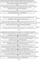
- FIG. 4 is a flowchart of a GNSS measurement method of an embodiment of the disclosure. The method is applied to a terminal. As illustrated in FIG. 4 , the method includes the following steps.
- first indication information is sent to a network device, in which the first indication information is configured to indicate whether the terminal supports the wireless communication system and the GNSS simultaneously.
- the first indication information is sent to the network device before the step of "in response to the expiration of the current GNSS position information of the terminal, performing the GNSS measurement in the connected state".
- "0" represents that the terminal has no ability of supporting both the wireless communication system and the GNSS to simultaneously work
- "1" represents that the terminal has an ability of supporting both the wireless communication system and the GNSS to simultaneously work.
- a measurement duration required for the GNSS measurement of the terminal may be determined and indicated to the network device.
- the GNSS measurement duration may be an average measurement duration over a period of time, the latest GNSS measurement duration, or a measurement duration agreed upon by a protocol or configured by a network.
- the terminal determines the measurement duration required for the GNSS measurement according to historical measurement situations and indicates the measurement duration to the network device.
- the terminal may indicate the measurement duration to the network device separately.
- the terminal may indicate the measurement duration to the network device via the first indication information.
- the measurement duration required for the GNSS measurement may represent a GNSS measurement capability of the terminal, and different durations correspond to different capabilities. For example, the shorter the measurement duration required for measurement, the higher the GNSS measurement capability.
- the GNSS measurement capability of the terminal can be expressed in levels, where capability 1 represents the highest level, and the larger the number, the lower the level.
- the measurement duration is indicated separately.
- the GNSS measurement duration of the terminal can be reported directly, or the level of the GNSS measurement capability can be determined according to the measurement duration and reported to the network device.
- the terminal synchronically indicates the measurement duration via the first indication information. For example, "00” may represent that the terminal does not support both the wireless communication system and the GNSS to simultaneously work, and "01” may represent that the terminal supports both the wireless communication system and the GNSS to simultaneously work and that the GNSS measurement capability of the terminal is capability 1. “10” may represent that the terminal supports both the wireless communication system and the GNSS to simultaneously work and that the GNSS measurement capability of the terminal is capability 2. “11” may represent that the terminal supports both the wireless communication system and the GNSS to simultaneously work and that the GNSS measurement capability of the terminal is capability 3.
- an RRC connection between the terminal and the network device is maintained at expiration of current GNSS position information, in which the terminal supports a wireless communication system and a GNSS simultaneously.
- a GNSS measurement is performed when the terminal is in a connected state.
- steps S402-S403 can be referred to the relevant descriptions in the embodiments of the disclosure and will not be repeated here.
- the terminal determines whether the terminal can perform a GNSS measurement in a connected state according to the first indication information sent by the terminal to the network device, the GNSS measurement duration is reported, and the network device can learn the GNSS measurement capability of the terminal according to the reported GNSS measurement duration. Moreover, an RRC connection between the terminal and the network device is maintained when the current GNSS position information of the terminal has expired, in which the terminal supports the wireless communication system and the GNSS simultaneously, and the terminal performs the GNSS measurement again in the connected state in response to the expiration of the current GNSS position information of the terminal. Through this method, the terminal can perform the GNSS measurement in the connected state in order to ensure that the terminal can obtain the GNSS position information in a timely and effective manner.
- FIG. 5 is a flowchart of a GNSS measurement method of an embodiment of the disclosure. The method is applied to a terminal. As illustrated in FIG. 5 , the method includes the following steps.
- step S501 measurement configuration information of GNSS measurement agreed upon by a protocol or indicated by a network is obtained, in which the measurement configuration information includes a measurement gap of the GNSS measurement.
- the measurement configuration information is used to instruct the terminal to perform a GNSS measurement within a measurement gap.
- the measurement configuration information is agreed upon by a protocol, and the measurement gap is a fixed value.
- the measurement configuration information is indicated by a network
- the measurement gap may be determined according to the first indication information sent by the terminal to the network device. That is, the network device may configure the measurement gap of the GNSS measurement according to the measurement duration of the terminal in the first indication information.
- the first indication information is configured to indicate whether the terminal supports the wireless communication system and the GNSS simultaneously, and it synchronically indicates the measurement duration of the terminal, so that the network device can obtain the GNSS measurement situation of the terminal based on the first indication information.
- the GNSS measurement gap can be configured for the terminal according to the measurement duration in the first indication information.
- an RRC connection between the terminal and a network device is maintained at expiration of current GNSS position information, in which the terminal supports a wireless communication system and a GNSS simultaneously.
- a GNSS measurement is performed again within a measurement gap configured for the terminal when the terminal is in a connected state.
- the terminal When the GNSS position information has expired, the terminal performs the GNSS measurement within the configured measurement gap.
- steps S502-S503 can be referred to the relevant descriptions in the embodiments of the disclosure, and will not be repeated here.
- the terminal performs the GNSS measurement within the configured time gap.
- the time gap can be configured according to the first indication information, so that the size of the time gap is more compatible with the measurement duration of the terminal.
- FIG. 6 is a flowchart of a GNSS measurement method of an embodiment of the disclosure. The method is applied to a terminal. As illustrated in FIG. 6 , the method includes the following steps.
- step S601 second indication information indicating that current GNSS position information is going to expire is sent to a network device.
- the terminal reports the second indication information within a preset time period before the expiration of the GNSS position information.
- the second indication information is used to indicate that the current GNSS position information of the terminal is about to expire.
- the preset time period can be agreed upon by a protocol or indicated by a network device via a signaling.
- the terminal may obtain an expiration time of the current GNSS position information and indicate the expiration time to the network device.
- the terminal obtains the expiration time of the current GNSS position information according to the validity period of the GNSS position information and an acquisition time of the current GNSS position information.
- the terminal may indicate the expiration time to the network device separately. In other implementations, the terminal may synchronically indicate the expiration time to the network device via the second indication information.
- the network device sends measurement confirmation information to the terminal.
- the measurement confirmation information is configured to indicate that the terminal is capable of performing the GNSS measurement.
- an RRC connection between the terminal and the network device is maintained at expiration of the current GNSS position information, in which the terminal supports a wireless communication system and a GNSS simultaneously.
- a GNSS measurement is performed when the terminal is in a connected state.
- the terminal performs the GNSS measurement within a measurement gap.
- the measurement gap may be agreed upon by a protocol or indicated by a network.
- steps S602-S603 can be referred to the relevant descriptions in the embodiments of the disclosure, and will not be repeated here.
- the terminal sends the second indication information to the network device when the current GNSS position information of the terminal is about to expire in order to instruct the terminal to carry out the GNSS measurement. No uplink or downlink transmission, monitoring or other operations will be performed during the measurement duration.
- FIG. 7 is a flowchart of a GNSS measurement method of an embodiment of the disclosure. The method is applied to a terminal. As illustrated in FIG. 7 , based on the GNSS measurement method provided in the disclosure, the process of GNSS measurement in a practical application scenario includes the following steps.
- first indication information is sent to a network device, in which the first indication information is used to indicate whether the terminal supports a wireless communication system and a GNSS simultaneously.
- step S702 measurement configuration information of GNSS measurement indicated by a network is obtained, in which the measurement configuration information includes a measurement gap of the GNSS measurement.
- step S703 second indication information indicating that current GNSS position information is about to expire is sent to the network device.
- step S704 measurement confirmation information sent by the network device is received, in which the measurement confirmation information is used to indicate that the terminal can perform the GNSS measurement.
- an RRC connection between the terminal and the network device is maintained at expiration of current GNSS position information, in which the terminal supports the wireless communication system and the GNSS simultaneously.
- a GNSS measurement is performed again within a measurement gap configured for the terminal when the terminal is in a connected state.
- the GNSS measurement capability of the terminal is obtained through the first indication information.
- the terminal is instructed to perform the GNSS measurement within a specified measurement gap through the measurement configuration information.
- notification and confirmation of the GNSS measurement is completed with the network device.
- the GNSS measurement is performed when the terminal is in the connected state to ensure that the terminal can update the GNSS position information in a timely and effective manner when the GNSS position information has expired, so that an accurate uplink synchronization information TA can be obtained, thereby avoiding uplink transmission interference between different terminals.
- FIG. 8 is a flowchart of a GNSS measurement method of an embodiment of the disclosure. The method is applied to a network device. As illustrated in FIG. 8 , the method includes the following step.
- step S801 it is determined that current GNSS position information of a terminal has expired, and the terminal is caused to maintain in a connected state and to perform a GNSS measurement.
- the terminal may perform the GNSS measurement again after entering an idle state, which may cause unnecessary delay and power consumption.
- a new mechanism may be introduced, so that the terminal can perform the GNSS measurement when it is in the connected state.
- the terminal can be caused to maintain in the connected state and perform the GNSS measurement to ensure that the terminal can obtain the GNSS position information in a timely and effective manner, thereby avoiding uplink transmission interference between different terminals.
- FIG. 9 is a flowchart of a GNSS measurement method of an embodiment of the disclosure. The method is applied to a network device. As illustrated in FIG. 9 , the method includes the following steps.
- step S901 first indication information sent by a terminal is received, in which the first indication information is configured to indicate whether the terminal supports a wireless communication system and a GNSS simultaneously.
- the first indication information indicates whether the terminal supports the wireless communication system and the GNSS simultaneously.
- the first indication information may synchronically indicate a measurement duration required for the GNSS measurement of the terminal.
- the measurement duration may also be indicated separately by the terminal.
- step S902 in response to the first indication information indicating that the terminal supports the wireless communication system and the GNSS simultaneously, an RRC connection between the terminal and the network device is maintained at expiration of the current GNSS position information of the terminal, so that the terminal can perform the GNSS measurement in a connected state.
- the terminal can perform the GNSS measurement in the connected state.
- the terminal can continue to maintain the RRC connection with the wireless communication system, so that it can maintain in the connected state and perform the GNSS measurement again without having to enter an idle state.
- the GNSS measurement situation of the terminal is determined based on the first indication information. Therefore, when the first indication information indicates that the terminal supports the wireless communication system and the GNSS simultaneously, the terminal maintains the RRC connection with the wireless communication system when the GNSS position information of the terminal has expired.
- the GNSS measurement can be performed while the terminal is in the connected state to ensure that the terminal can obtain the GNSS position information in a timely and effective manner, thereby avoiding uplink transmission interference between different terminals.
- FIG. 10 is a flowchart of a GNSS measurement method of an embodiment of the disclosure. The method is applied to a network device. As illustrated in FIG. 10 , the method includes the following steps.
- step S1001 first indication information sent by a terminal is received.
- step S1001 can be referred to the relevant descriptions in the embodiments of the disclosure and will not be repeated here.
- step S1002 measurement configuration information of GNSS measurement is determined based on the first indication information and sent to the terminal, in which the measurement configuration information includes a measurement gap of the GNSS measurement.
- a measurement duration required for the GNSS measurement is determined.
- a suitable measurement gap is configured for the terminal and sent to the terminal.
- the measurement gap may also be agreed upon by a protocol or set as a fixed value.
- an RRC connection between the terminal and the network device is maintained at expiration of the current GNSS position information of the terminal, so that the terminal performs the GNSS measurement in a connected state.
- step S1003 can be referred to the relevant descriptions in the embodiments of the disclosure and will not be repeated here.
- a time gap is configured according to the first indication information, so that the size of the time gap can be more compatible with the measurement duration of the terminal.
- FIG. 11 is a flowchart of a GNSS measurement method of an embodiment of the disclosure. The method is applied to a network device. As illustrated in FIG. 11 , the method includes the following steps.
- step S1101 second indication information sent by a terminal is received, in which the second indication information indicates that the current GNSS position information is going to expire.
- the second indication information indicates that the current GNSS position information is about to expire.
- the second indication information may synchronically indicate an expiration time of the GNSS position information.
- the expiration time may also be separately indicated by the terminal.
- step S1102 measurement confirmation information is sent to the terminal, in which the measurement confirmation information is configured to indicate that the terminal is capable of performing the GNSS measurement.
- an RRC connection between the terminal and the network device is maintained at expiration of the current GNSS position information of the terminal, so that the terminal performs the GNSS measurement in a connected state.
- steps S1002-S1003 can be referred to the relevant descriptions in the embodiments of the disclosure and will not be repeated here.
- the notification and confirmation of the GNSS measurement is completed through the second indication information and the measurement confirmation information, and the terminal may not perform any uplink and downlink transmission, monitoring, and other operations during the measurement duration.
- FIG. 12 is a flowchart of a GNSS measurement method of an embodiment of the disclosure. The method is applied to a network device. As illustrated in FIG. 12 , based on the GNSS measurement method provided in the disclosure, the process of GNSS measurement in a practical application scenario includes the following steps.
- step S1201 first indication information sent by a terminal is received, in which the first indication information is used to indicate whether the terminal supports a wireless communication system and a GNSS simultaneously.
- step S1202 measurement configuration information of GNSS measurement is determined according to the first indication information and sent to the terminal, in which the measurement configuration information includes a measurement gap of the GNSS measurement.
- step S1203 second indication information sent by the terminal that indicates that current GNSS position information is about to expire is received.
- step S 1204 measurement confirmation information is sent to the terminal, in which the measurement confirmation information is used to indicate that the terminal can perform the GNSS measurement.
- step S 1205 an RRC connection between the terminal and the network device is maintained at expiration of the current GNSS position information of the terminal, so that the terminal can perform the GNSS measurement in a connected state.
- the GNSS measurement capability of the terminal is obtained through the first indication information.
- the terminal is instructed to perform the GNSS measurement within the specified measurement gap via the measurement configuration information.
- notification and confirmation of the GNSS measurement is completed with the network device.
- the GNSS measurement is performed when the terminal is in the connected state to ensure that the terminal can update the GNSS position information in a timely and effective manner when the GNSS position information has expired, so that an accurate uplink synchronization information TA can be obtained, thereby avoiding uplink transmission interference between different terminals.
- the method provided in the embodiments of the disclosure is described from the perspective of a network device and a terminal, respectively.
- the network device and the terminal may include a hardware structure and/or a software module, and realize each of the above-described functions in the form of a hardware structure, a software module, or a combination of the hardware structure and the software module.
- a certain function of the above-described functions may be performed in the form of a hardware structure, a software module, or a combination of the hardware structure and the software module.
- FIG. 13 is a block diagram of a communication apparatus 1300 provided by an embodiment of the disclosure.
- the communication apparatus 1300 shown in FIG. 13 may include a transceiver module 1310 and a processing module 1320.
- the transceiver module 1310 may include a transmitting module and a receiving module, the transmitting module is used to implement a transmitting function, and the receiving module is used to implement a receiving function.
- the transceiver module 1310 may implement a transmitting function and a receiving function.
- the communication apparatus 1300 may be a terminal, an apparatus in the terminal, or an apparatus capable of being used together with the terminal.
- the communication apparatus 1300 may be a network device, an apparatus in the network device, or an apparatus capable of being used together with the network device.
- the processing module 1320 is configured to perform a GNSS measurement in a connected state in response to expiration of current GNSS position information of the terminal.
- the processing module 1320 is configured to: maintain an RRC connection between the terminal and a network device at the expiration of the current GNSS position information, in which the terminal supports a wireless communication system and a GNSS simultaneously.
- the communication apparatus 1300 includes the transceiver module 1310, configured to send first indication information to the network device, in which the first indication information is configured to indicate whether the terminal supports the wireless communication system and the GNSS simultaneously.
- the transceiver module 1310 is configured to: determine a measurement duration required for the GNSS measurement of the terminal and indicate the measurement duration to the network device.
- the transceiver module 1310 is configured to: indicate the measurement duration synchronically through the first indication information.
- the transceiver module 1310 is configured to: obtain measurement configuration information of the GNSS measurement agreed upon by a protocol or indicated by a network, in which the measurement configuration information includes a measurement gap of the GNSS measurement.
- the processing module 1320 is configured to: perform the GNSS measurement within the measurement gap configured for the terminal.
- the transceiver module 1310 is configured to: receive measurement configuration information sent by the network device, in which the measurement configuration information is determined based on the first indication information sent by the terminal to the network device.
- the transceiver module 1310 is configured to: send second indication information indicating that the current GNSS position information is going to expire to the network device.
- the transceiver module 1310 is configured to: obtain an expiration time of the current GNSS position information, and indicate the expiration time to the network device.
- the transceiver module 1310 is configured to: indicate the expiration time synchronically through the second indication information.
- the transceiver module 1310 is configured to: receive measurement confirmation information sent by the network device, in which the measurement confirmation information is configured to indicate that the terminal is capable of performing the GNSS measurement.
- the processing module 1320 is configured to: determine that current GNSS position information of a terminal has expired, and cause the terminal to maintain in a connected state and to perform a GNSS measurement.
- the communication apparatus 1300 further includes the transceiver module 1310, configured to: receive first indication information sent by the terminal, in which the first indication information is configured to indicate whether the terminal supports a wireless communication system and a GNSS simultaneously.
- the processing module 1320 is configured to: maintain an RRC connection between the terminal and the network device at expiration of the current GNSS position information of the terminal, in response to the first indication information indicating that the terminal supports the wireless communication system and the GNSS simultaneously.
- the transceiver module 1310 is configured to: obtain a measurement duration required for the GNSS measurement of the terminal.
- the processing module 1320 is configured to: determine the measurement duration based on the first indication information.
- the processing module 1320 is configured to: determine measurement configuration information of the GNSS measurement based on the first indication information and send the measurement configuration information to the terminal, in which the measurement configuration information includes a measurement gap of the GNSS measurement.
- the transceiver module 1310 is configured to: receive second indication information sent by the terminal that indicates that the current GNSS position information is going to expire.
- the transceiver module 1310 is configured to: obtain an expiration time of the current GNSS position information.
- the processing module 1320 is configured to: determine the expiration time based on the second indication information.
- the transceiver module 1310 is configured to: send measurement confirmation information to the terminal, in which the measurement confirmation information is configured to indicate that the terminal is capable of performing the GNSS measurement.
- FIG. 14 is a schematic diagram illustrating a communication apparatus 1400 according to an embodiment of the disclosure.
- the communication apparatus 1400 may be a network device, a terminal, or may be a chip, a chip system or a processor that supports the network device to realize the above-described methods, or may be a chip, a chip system or a processor that supports the terminal to realize the above-described methods.
- the communication apparatus may be used to realize the methods described in the above method embodiments with reference to the descriptions of the above-described method embodiments.
- the communication apparatus 1400 may include one or more processors 1410.
- the processor 1410 may be a general purpose processor or a dedicated processor, such as, a baseband processor or a central processor.
- the baseband processor is used for processing communication protocols and communication data.
- the central processor is used for controlling the communication apparatus (e.g., base station, baseband chip, terminal, terminal chip, DU, or CU), executing computer programs, and processing data of the computer programs.
- the communication apparatus 1400 may include one or more memories 1420 on which computer programs 1440 may be stored.
- the processor 1410 executes the computer programs 1440 to cause the communication apparatus 1400 to perform the methods described in the above method embodiments.
- data may also be stored in the memory 1420.
- the communication apparatus 1400 and the memory 1420 may be provided separately or may be integrated together.
- the communication apparatus 1400 may also include a transceiver 1450 and an antenna 1460.
- the transceiver 1450 may be referred to as transceiver unit, transceiver machine, or transceiver circuit, for realizing the transceiver function.
- the transceiver 1450 may include a receiver and a transmitter.
- the receiver may be referred to as receiver machine or receiving circuit, for realizing the receiving function.
- the transmitter may be referred to as transmitter machine or transmitting circuit, for realizing the transmitting function.
- the communication apparatus 1400 may also include one or more interface circuits 1470.
- the interface circuits 1470 are used to receive code instructions and transmit them to the processor 1410.
- the processor 1410 runs the code instructions to cause the communication apparatus 1400 to perform the method described in the method embodiments.
- the processor 1410 may include a transceiver for implementing the receiving and transmitting functions.
- the transceiver may be, for example, a transceiver circuit, an interface, or an interface circuit.
- the transceiver circuit, interface, or interface circuit for implementing the receiving and transmitting functions may be separated or may be integrated together.
- the transceiver circuit, interface, or interface circuit described above may be used for code/data reading and writing, or may be used for signal transmission or delivery.
- the processor 1410 may store a computer program 1430, which runs on the processor 1410 and may cause the communication apparatus 1400 to perform the methods described in the method embodiments above.
- the computer program 1430 may be solidified in the processor 1410, in which case the processor 1410 may be implemented by hardware.
- the communication apparatus 1400 may include circuits.
- the circuits may implement the sending, receiving or communicating function in the preceding method embodiments.
- the processors and transceivers described in this disclosure may be implemented on integrated circuits (ICs), analog ICs, radio frequency integrated circuits (RFICs), mixed signal ICs, application specific integrated circuits (ASICs), printed circuit boards (PCBs), and electronic devices.
- ICs integrated circuits
- RFICs radio frequency integrated circuits
- ASICs application specific integrated circuits
- PCBs printed circuit boards
- CMOS complementary metal oxide semiconductor
- NMOS nMetal-oxide-semiconductor
- PMOS positive channel metal oxide semiconductor
- BJT bipolar junction transistor
- BiCMOS bipolar CMOS
- SiGe silicon-germanium
- GaAs gallium arsenide
- the communication apparatus in the above description of embodiments may be a network device or a terminal, but the scope of the communication apparatus described in the disclosure is not limited thereto, and the structure of the communication apparatus may not be limited by FIG. 14 .
- the communication apparatus may be a stand-alone device or may be part of a larger device.
- the described communication apparatus may be:
- the case where the communication apparatus may be a chip or a chip system is described with reference to the schematic structure of the chip shown in FIG. 15 .
- the chip shown in FIG. 15 includes a processor 1510 and an interface 1520. There may be one or more processors 1510, and there may be multiple interfaces 1520.
- the chip further includes a memory 1530 used for storing necessary computer programs and data.
- Embodiments of the disclosure also provide a system.
- the system includes a communication apparatus as a terminal and a communication apparatus as a network device in the preceding embodiment of FIG. 13 .
- the system includes a communication apparatus as a terminal and a communication apparatus as a network device in the preceding embodiment of FIG. 14 .
- the disclosure also provides a readable storage medium having instructions stored thereon. When the instructions are executed by a computer, the function of any of the method embodiments described above is implemented.
- the disclosure also provides a computer program product.
- the computer program product is executed by a computer, the function of any of the method embodiments described above is implemented.
- the above embodiments may be implemented in whole or in part by software, hardware, firmware, or any combination thereof.
- software When implemented using software, it may be implemented, in whole or in part, in the form of a computer program product.
- the computer program product includes one or more computer programs. When loading and executing the computer program on the computer, all or part of processes or functions described in the embodiments of the disclosure is implemented.
- the computer may be a general-purpose computer, a dedicated computer, a computer network, or other programmable devices.
- the computer program may be stored in a computer-readable storage medium or transmitted from one computer-readable storage medium to another computer-readable storage medium.
- the computer program may be transmitted from one web site, computer, server, or data center to another web site, computer, server, or data center, in a wired manner (e.g., by using coaxial cables, fiber optics, or digital subscriber lines (DSLs) or wirelessly (e.g., by using infrared wave, wireless wave, or microwave).
- the computer-readable storage medium may be any usable medium to which the computer has access to or a data storage device such as a server and a data center integrated by one or more usable mediums.
- the usable medium may be a magnetic medium (e.g., floppy disk, hard disk, and tape), an optical medium (e.g., a high-density digital video disc (DVD)), or a semiconductor medium (e.g., a solid state disk (SSD)).
- a magnetic medium e.g., floppy disk, hard disk, and tape
- an optical medium e.g., a high-density digital video disc (DVD)
- DVD high-density digital video disc
- SSD solid state disk
- the term “multiple” in the disclosure refers to two or more, which is similar for other quantifiers.
- the term “and/or” describes a relation of associated objects, which indicates three relations, for example, "A and/or B” indicates that A exists alone, A and B both exist, and B exists alone.
- the character “/” generally indicates that the associated objects prior to and after the character “j” is an “or” relation.
- the terms “a”, “said” and “the” in the singular form are also intended to include the plural form, unless the context clearly indicates otherwise.
- first, second, and third may be used in the disclosure to describe various information, the information should not be limited to these terms. These terms are only used to distinguish the same type of information from each other.
- first information may also be referred to as the second information, and similarly, the second information may also be referred to as the first information.
- second information may also be referred to as the first information.
- if' as used herein can be interpreted as "when", “while” or "in response to determining”.
- the term “at least one” in the disclosure may also be described as one or more, and the term “multiple” may be two, three, four, or more, which is not limited in the disclosure.
- “first”, “second”, and “third”, and “A”, “B”, “C” and “D” are used to distinguish different technical features of the type, the technical features described using the “first”, “second”, and “third”, and “A”, “B”, “C” and “D” do not indicate any order of precedence or magnitude.
- the correspondences shown in the tables in this disclosure may be configured or may be predefined.
- the values of information in the tables are merely examples and may be configured to other values, which are not limited by the disclosure.
- the correspondences illustrated in certain rows in the tables in this disclosure may not be configured.
- the above tables may be adjusted appropriately, such as splitting, combining, and the like.
- the names of the parameters shown in the titles of the above tables may be other names that can be understood by the communication apparatus, and the values or representations of the parameters may be other values or representations that can be understood by the communication apparatus.
- Each of the above tables may also be implemented with other data structures, such as, arrays, queues, containers, stacks, linear tables, pointers, chained lists, trees, graphs, structures, classes, heaps, and Hash tables.
- predefine in this disclosure may be understood as define, define in advance, store, pre-store, pre-negotiate, pre-configure, solidify, or pre-fire.
Landscapes
- Engineering & Computer Science (AREA)
- Computer Networks & Wireless Communication (AREA)
- Radar, Positioning & Navigation (AREA)
- Remote Sensing (AREA)
- Signal Processing (AREA)
- Physics & Mathematics (AREA)
- General Physics & Mathematics (AREA)
- Mobile Radio Communication Systems (AREA)
Applications Claiming Priority (1)
| Application Number | Priority Date | Filing Date | Title |
|---|---|---|---|
| PCT/CN2021/139335 WO2023108656A1 (zh) | 2021-12-17 | 2021-12-17 | 一种全球卫星导航系统gnss的测量方法及其装置 |
Publications (2)
| Publication Number | Publication Date |
|---|---|
| EP4451015A1 true EP4451015A1 (de) | 2024-10-23 |
| EP4451015A4 EP4451015A4 (de) | 2025-09-17 |
Family
ID=81104929
Family Applications (1)
| Application Number | Title | Priority Date | Filing Date |
|---|---|---|---|
| EP21967788.7A Pending EP4451015A4 (de) | 2021-12-17 | 2021-12-17 | Messverfahren und -vorrichtung für ein globales navigationssatellitensystem (gnss) |
Country Status (4)
| Country | Link |
|---|---|
| US (1) | US20250155582A1 (de) |
| EP (1) | EP4451015A4 (de) |
| CN (1) | CN114365016A (de) |
| WO (1) | WO2023108656A1 (de) |
Cited By (1)
| Publication number | Priority date | Publication date | Assignee | Title |
|---|---|---|---|---|
| EP4598064A4 (de) * | 2022-10-31 | 2025-12-24 | Guangdong Oppo Mobile Telecommunications Corp Ltd | Positionsmessverfahren, timer-wartungsverfahren und vorrichtung |
Families Citing this family (31)
| Publication number | Priority date | Publication date | Assignee | Title |
|---|---|---|---|---|
| WO2023225826A1 (zh) * | 2022-05-23 | 2023-11-30 | 北京小米移动软件有限公司 | 定位系统信息的获取方法和装置 |
| US20250370138A1 (en) * | 2022-06-13 | 2025-12-04 | Beijing Xiaoml Mobile Software Co., Ltd. | Method and apparatus for indicating global navigation satellite system (gnss) measurement |
| US20250370139A1 (en) * | 2022-06-15 | 2025-12-04 | Beijing Xiaomi Mobile Software Co., Ltd. | Positioning measurement method and apparatus for global navigation satellite system (gnss) |
| CN115280875A (zh) * | 2022-06-24 | 2022-11-01 | 北京小米移动软件有限公司 | 全球导航卫星系统gnss定位测量方法及装置 |
| CN118891854A (zh) * | 2022-06-29 | 2024-11-01 | Oppo广东移动通信有限公司 | 通信方法及通信装置 |
| CN119343611A (zh) * | 2022-07-01 | 2025-01-21 | 中兴通讯股份有限公司 | 无线通信方法及其无线终端和无线网络节点 |
| CN120110488B (zh) * | 2022-08-02 | 2026-03-27 | 华为技术有限公司 | 一种通信方法及装置 |
| CN115812328A (zh) * | 2022-09-27 | 2023-03-17 | 北京小米移动软件有限公司 | 全球导航卫星系统gnss信息的生效时间确定方法及装置 |
| WO2024065223A1 (zh) * | 2022-09-27 | 2024-04-04 | 北京小米移动软件有限公司 | 全球导航卫星系统gnss信息的测量方法及装置 |
| WO2024092662A1 (zh) * | 2022-11-03 | 2024-05-10 | 北京小米移动软件有限公司 | 时间信息上报方法、装置、通信设备及存储介质 |
| CN115997139A (zh) * | 2022-11-04 | 2023-04-21 | 北京小米移动软件有限公司 | 定位测量方法、装置、通信设备及存储介质 |
| CN118244312A (zh) * | 2022-12-22 | 2024-06-25 | 联发科技(新加坡)私人有限公司 | 用于全球导航卫星系统操作的方法及装置 |
| EP4645770A4 (de) * | 2022-12-26 | 2026-03-11 | Beijing Xiaomi Mobile Software Co Ltd | Verfahren zur bestimmung der messkapazität eines globalen navigationssatellitensystems (gnss) und vorrichtung |
| WO2024148465A1 (zh) * | 2023-01-09 | 2024-07-18 | Oppo广东移动通信有限公司 | 测量方法和终端设备 |
| WO2024159341A1 (zh) * | 2023-01-30 | 2024-08-08 | 北京小米移动软件有限公司 | Gnss测量方法、装置、设备及存储介质 |
| EP4661554A4 (de) * | 2023-01-30 | 2026-03-11 | Beijing Xiaomi Mobile Software Co Ltd | Verfahren und vorrichtung zur bestimmung der priorität eines logischen kanals und vorrichtung |
| CN116324512A (zh) * | 2023-01-30 | 2023-06-23 | 北京小米移动软件有限公司 | Gnss测量方法、装置、设备及存储介质 |
| EP4661549A4 (de) * | 2023-01-30 | 2026-03-18 | Beijing Xiaomi Mobile Software Co Ltd | Drahtloskommunikationsverfahren und -vorrichtung, vorrichtung, speichermedium und programmprodukt |
| CN118534493A (zh) * | 2023-02-15 | 2024-08-23 | 展讯半导体(南京)有限公司 | Gnss测量方法、装置以及设备 |
| EP4671827A1 (de) * | 2023-02-22 | 2025-12-31 | Beijing Xiaomi Mobile Software Co., Ltd. | Gnss-messverfahren und -vorrichtung |
| WO2024178674A1 (en) * | 2023-03-01 | 2024-09-06 | Mediatek Singapore Pte. Ltd. | Gnss measurement gap procedures in rrc connected |
| WO2024197532A1 (zh) * | 2023-03-27 | 2024-10-03 | 北京小米移动软件有限公司 | 测量方法以及装置、通信设备及存储介质 |
| WO2024229774A1 (zh) * | 2023-05-10 | 2024-11-14 | 北京小米移动软件有限公司 | 测量方法、装置及计算机可读存储介质 |
| CN116868615A (zh) * | 2023-05-12 | 2023-10-10 | 北京小米移动软件有限公司 | 通信方法及装置、设备、系统、计算机可读存储介质 |
| WO2024234264A1 (zh) * | 2023-05-15 | 2024-11-21 | 北京小米移动软件有限公司 | 通信方法、通信装置、通信设备、通信系统和存储介质 |
| CN117546549A (zh) * | 2023-09-22 | 2024-02-09 | 北京小米移动软件有限公司 | 信息指示方法及通信设备、通信系统及存储介质 |
| CN119727842A (zh) * | 2023-09-27 | 2025-03-28 | 华为技术有限公司 | 卫星通信方法及装置 |
| WO2025065656A1 (en) * | 2023-09-28 | 2025-04-03 | Nokia Shanghai Bell Co., Ltd. | Positioning measurement with insufficient measurement time duration |
| CN120530690A (zh) * | 2023-12-22 | 2025-08-22 | 北京小米移动软件有限公司 | 与上行传输相关的信息处理方法、装置及存储介质 |
| CN120264402A (zh) * | 2023-12-27 | 2025-07-04 | 展讯半导体(南京)有限公司 | 通信方法及装置、计算机可读存储介质 |
| WO2025231668A1 (zh) * | 2024-05-08 | 2025-11-13 | Oppo广东移动通信有限公司 | 用于无线通信的方法和终端设备 |
Family Cites Families (10)
| Publication number | Priority date | Publication date | Assignee | Title |
|---|---|---|---|---|
| CN103313185B (zh) * | 2012-03-16 | 2016-08-31 | 电信科学技术研究院 | 位置信息获取方法和设备 |
| EP2882210A4 (de) * | 2012-08-03 | 2016-03-09 | Kyocera Corp | Benutzerendgerät, prozessor und verfahren dafür |
| WO2019086309A1 (en) * | 2017-10-30 | 2019-05-09 | Sony Corporation | Terminal device, infrastructure equipment and methods |
| CN110139314B (zh) * | 2018-02-09 | 2022-11-08 | 中国移动通信集团终端有限公司 | Mdt终端测量位置信息的方法、装置、设备及介质 |
| CN110858951B (zh) * | 2018-08-22 | 2021-06-18 | 中国移动通信有限公司研究院 | 实现用户终端定位的方法、用户终端、网络侧设备 |
| CN112449403B (zh) * | 2019-09-05 | 2023-10-20 | 海能达通信股份有限公司 | 低轨卫星通信中的随机接入信道传输方法及装置 |
| CN110446254B (zh) * | 2019-09-12 | 2021-11-23 | 上海众睿通信科技有限公司 | 一种用于卫星通信系统的上行定时提前量终端预测方法 |
| WO2021133239A1 (en) * | 2019-12-23 | 2021-07-01 | Telefonaktiebolaget Lm Ericsson (Publ) | Gnss measurement gaps |
| WO2021179324A1 (zh) * | 2020-03-13 | 2021-09-16 | 北京小米移动软件有限公司 | 终端定位的方法、装置、通信设备及存储介质 |
| CN113612523B (zh) * | 2021-08-23 | 2023-02-28 | 东方红卫星移动通信有限公司 | 上行时间预补偿算法、终端同步方法及系统 |
-
2021
- 2021-12-17 US US18/720,454 patent/US20250155582A1/en active Pending
- 2021-12-17 WO PCT/CN2021/139335 patent/WO2023108656A1/zh not_active Ceased
- 2021-12-17 CN CN202180004417.3A patent/CN114365016A/zh active Pending
- 2021-12-17 EP EP21967788.7A patent/EP4451015A4/de active Pending
Cited By (1)
| Publication number | Priority date | Publication date | Assignee | Title |
|---|---|---|---|---|
| EP4598064A4 (de) * | 2022-10-31 | 2025-12-24 | Guangdong Oppo Mobile Telecommunications Corp Ltd | Positionsmessverfahren, timer-wartungsverfahren und vorrichtung |
Also Published As
| Publication number | Publication date |
|---|---|
| EP4451015A4 (de) | 2025-09-17 |
| WO2023108656A1 (zh) | 2023-06-22 |
| CN114365016A (zh) | 2022-04-15 |
| US20250155582A1 (en) | 2025-05-15 |
Similar Documents
| Publication | Publication Date | Title |
|---|---|---|
| EP4451015A1 (de) | Messverfahren und -vorrichtung für ein globales navigationssatellitensystem (gnss) | |
| JP7686877B2 (ja) | 伝送設定指示(tci)状態設定方法及びその装置 | |
| EP4518201A1 (de) | Verfahren und vorrichtung zur bestimmung des konfigurationsanzeigezustands | |
| EP4518202A1 (de) | Verfahren zur bestimmung des anzeigestatus einer übertragungskonfiguration und vorrichtung | |
| CN115280185B (zh) | 全球导航卫星系统gnss定位测量方法及装置 | |
| CN112399546A (zh) | 公共定时提前的指示方法、装置、设备及存储介质 | |
| CN115280875A (zh) | 全球导航卫星系统gnss定位测量方法及装置 | |
| EP4614191A1 (de) | Verfahren und vorrichtung zur positionsmessung, kommunikationsvorrichtung und speichermedium | |
| EP4539566A1 (de) | Verfahren und vorrichtung zur anzeige der messung eines globalen navigationssatellitensystems (gnss) | |
| EP4503457A1 (de) | Verfahren und vorrichtung zur bestimmung der effektiven zeit | |
| EP4376509A1 (de) | Verfahren und vorrichtung zur meldung von positionsinformationen eines endgerätes in einem nicht terrestrischen netzwerk | |
| WO2024138337A1 (zh) | 全球导航卫星系统gnss测量能力的确定方法及装置 | |
| EP4451594A1 (de) | Positionierungsverfahren und -vorrichtung | |
| EP4429397A1 (de) | Verfahren zur bestimmung von positionsinformationen einer endgerätevorrichtung und vorrichtung dafür | |
| EP4518211A1 (de) | Verarbeitungsverfahren für rückkopplung von hybriden automatischen wiederholungsanfragen (harq) und vorrichtung dafür | |
| US20240422719A1 (en) | Location information updating method and apparatus | |
| CN115413406B (zh) | 物理随机接入信道prach的配置方法及其装置 | |
| WO2024016360A1 (zh) | 一种随机接入方法/装置/设备及存储介质 | |
| CN114026907A (zh) | 一种上行波束的测量方法及其装置 | |
| EP4583594A1 (de) | Verfahren und vorrichtung zur messung von zeitvorlauf (ta) | |
| US20250234409A1 (en) | Methods for indicating radio resource management (rrm) requirement enhancement and apparatuses therefor | |
| EP4382966A1 (de) | Verfahren und vorrichtung zur positionsmessung | |
| EP4401495A1 (de) | Verfahren und vorrichtung zur bestimmung eines zeitversatzes | |
| US20250219697A1 (en) | Channel state information (csi) report acquisition method and apparatus, and storage medium | |
| WO2024031485A1 (zh) | 一种传输方法及其装置 |
Legal Events
| Date | Code | Title | Description |
|---|---|---|---|
| STAA | Information on the status of an ep patent application or granted ep patent |
Free format text: STATUS: THE INTERNATIONAL PUBLICATION HAS BEEN MADE |
|
| PUAI | Public reference made under article 153(3) epc to a published international application that has entered the european phase |
Free format text: ORIGINAL CODE: 0009012 |
|
| STAA | Information on the status of an ep patent application or granted ep patent |
Free format text: STATUS: REQUEST FOR EXAMINATION WAS MADE |
|
| 17P | Request for examination filed |
Effective date: 20240716 |
|
| AK | Designated contracting states |
Kind code of ref document: A1 Designated state(s): AL AT BE BG CH CY CZ DE DK EE ES FI FR GB GR HR HU IE IS IT LI LT LU LV MC MK MT NL NO PL PT RO RS SE SI SK SM TR |
|
| DAV | Request for validation of the european patent (deleted) | ||
| DAX | Request for extension of the european patent (deleted) | ||
| A4 | Supplementary search report drawn up and despatched |
Effective date: 20250821 |
|
| RIC1 | Information provided on ipc code assigned before grant |
Ipc: G01S 19/42 20100101AFI20250814BHEP Ipc: G01S 19/14 20100101ALI20250814BHEP Ipc: G01S 19/34 20100101ALI20250814BHEP Ipc: H04B 7/185 20060101ALI20250814BHEP Ipc: H04W 52/02 20090101ALI20250814BHEP Ipc: H04W 56/00 20090101ALI20250814BHEP Ipc: H04W 64/00 20090101ALI20250814BHEP |