EP4451006A1 - Distance image measuring device, and distance image measuring method - Google Patents
Distance image measuring device, and distance image measuring method Download PDFInfo
- Publication number
- EP4451006A1 EP4451006A1 EP22911311.3A EP22911311A EP4451006A1 EP 4451006 A1 EP4451006 A1 EP 4451006A1 EP 22911311 A EP22911311 A EP 22911311A EP 4451006 A1 EP4451006 A1 EP 4451006A1
- Authority
- EP
- European Patent Office
- Prior art keywords
- charge
- readout
- regions
- charge readout
- sub
- Prior art date
- Legal status (The legal status is an assumption and is not a legal conclusion. Google has not performed a legal analysis and makes no representation as to the accuracy of the status listed.)
- Pending
Links
Images




Classifications
-
- H—ELECTRICITY
- H04—ELECTRIC COMMUNICATION TECHNIQUE
- H04N—PICTORIAL COMMUNICATION, e.g. TELEVISION
- H04N25/00—Circuitry of solid-state image sensors [SSIS]; Control thereof
- H04N25/70—SSIS architectures; Circuits associated therewith
- H04N25/703—SSIS architectures incorporating pixels for producing signals other than image signals
- H04N25/705—Pixels for depth measurement, e.g. RGBZ
-
- G—PHYSICS
- G01—MEASURING; TESTING
- G01S—RADIO DIRECTION-FINDING; RADIO NAVIGATION; DETERMINING DISTANCE OR VELOCITY BY USE OF RADIO WAVES; LOCATING OR PRESENCE-DETECTING BY USE OF THE REFLECTION OR RERADIATION OF RADIO WAVES; ANALOGOUS ARRANGEMENTS USING OTHER WAVES
- G01S7/00—Details of systems according to groups G01S13/00, G01S15/00, G01S17/00
- G01S7/48—Details of systems according to groups G01S13/00, G01S15/00, G01S17/00 of systems according to group G01S17/00
- G01S7/483—Details of pulse systems
- G01S7/486—Receivers
- G01S7/4861—Circuits for detection, sampling, integration or read-out
- G01S7/4863—Detector arrays, e.g. charge-transfer gates
-
- G—PHYSICS
- G01—MEASURING; TESTING
- G01S—RADIO DIRECTION-FINDING; RADIO NAVIGATION; DETERMINING DISTANCE OR VELOCITY BY USE OF RADIO WAVES; LOCATING OR PRESENCE-DETECTING BY USE OF THE REFLECTION OR RERADIATION OF RADIO WAVES; ANALOGOUS ARRANGEMENTS USING OTHER WAVES
- G01S17/00—Systems using the reflection or reradiation of electromagnetic waves other than radio waves, e.g. lidar systems
- G01S17/02—Systems using the reflection of electromagnetic waves other than radio waves
- G01S17/06—Systems determining position data of a target
- G01S17/08—Systems determining position data of a target for measuring distance only
- G01S17/10—Systems determining position data of a target for measuring distance only using transmission of interrupted, pulse-modulated waves
-
- G—PHYSICS
- G01—MEASURING; TESTING
- G01S—RADIO DIRECTION-FINDING; RADIO NAVIGATION; DETERMINING DISTANCE OR VELOCITY BY USE OF RADIO WAVES; LOCATING OR PRESENCE-DETECTING BY USE OF THE REFLECTION OR RERADIATION OF RADIO WAVES; ANALOGOUS ARRANGEMENTS USING OTHER WAVES
- G01S17/00—Systems using the reflection or reradiation of electromagnetic waves other than radio waves, e.g. lidar systems
- G01S17/88—Lidar systems specially adapted for specific applications
- G01S17/89—Lidar systems specially adapted for specific applications for mapping or imaging
- G01S17/894—Three-dimensional [3D] imaging with simultaneous measurement of time-of-flight at a two-dimensional [2D] array of receiver pixels, e.g. time-of-flight cameras or flash lidar
-
- G—PHYSICS
- G01—MEASURING; TESTING
- G01S—RADIO DIRECTION-FINDING; RADIO NAVIGATION; DETERMINING DISTANCE OR VELOCITY BY USE OF RADIO WAVES; LOCATING OR PRESENCE-DETECTING BY USE OF THE REFLECTION OR RERADIATION OF RADIO WAVES; ANALOGOUS ARRANGEMENTS USING OTHER WAVES
- G01S7/00—Details of systems according to groups G01S13/00, G01S15/00, G01S17/00
- G01S7/48—Details of systems according to groups G01S13/00, G01S15/00, G01S17/00 of systems according to group G01S17/00
- G01S7/483—Details of pulse systems
- G01S7/484—Transmitters
-
- G—PHYSICS
- G01—MEASURING; TESTING
- G01S—RADIO DIRECTION-FINDING; RADIO NAVIGATION; DETERMINING DISTANCE OR VELOCITY BY USE OF RADIO WAVES; LOCATING OR PRESENCE-DETECTING BY USE OF THE REFLECTION OR RERADIATION OF RADIO WAVES; ANALOGOUS ARRANGEMENTS USING OTHER WAVES
- G01S7/00—Details of systems according to groups G01S13/00, G01S15/00, G01S17/00
- G01S7/48—Details of systems according to groups G01S13/00, G01S15/00, G01S17/00 of systems according to group G01S17/00
- G01S7/483—Details of pulse systems
- G01S7/486—Receivers
- G01S7/4865—Time delay measurement, e.g. time-of-flight measurement, time of arrival measurement or determining the exact position of a peak
Definitions
- the present disclosure relates to a distance image measuring device and a distance image measuring method for generating a distance image including distance information for each pixel.
- Patent Literature 1 a device that generates an image signal including distance information using a time of flight of light has been used (see, for example, Patent Literature 1 below).
- the device described in Patent Literature 1 below generates pulsed light from a light source, accumulates charges generated in response to the pulsed light in a plurality of charge readout regions in a pixel circuit in different periods set by control pulses, reads out voltages of the plurality of charge readout regions as detection signals and calculates a distance for each pixel based on the detection signals to acquire distance information.
- Patent Literature 1 WO 2019/078366 A
- the present disclosure has been made in view of the above problem, and an object of the present disclosure is to provide a distance image measuring device and a distance image measuring method capable of generating an image signal with improved distance resolution in a case where an object in a wide distance range is to be measured.
- a distance image measuring device includes: a light source configured to generate pulsed light; a light source control unit configured to control the light source so as to repeatedly generate the pulsed light within a periodic frame period; a pixel circuit unit including a photoelectric conversion region that converts light into charges, first to M-th (M is an integer equal to or greater than 2) charge readout regions provided close to the photoelectric conversion region and spaced apart from each other, and first to M-th control electrodes respectively provided corresponding to the photoelectric conversion region and the first to the M-th charge readout regions and provided for applying first to M-th control pulses for charge transfer between the photoelectric conversion region and the first to the M-th charge readout regions; a charge transfer control unit configured to repeatedly apply the first to the M-th control pulses to the first to the M-th control electrodes within the frame period while being delayed from a generation timing of the pulsed light by the light source control unit, and a signal readout unit configured to read out detection signals corresponding to
- a distance image measuring method includes: a light source control step of a light source control unit controlling a light source so as to repeatedly generate pulsed light within a periodic frame period; a charge transfer control step of, using a pixel circuit unit including a photoelectric conversion region that converts light into charges, first to M-th (M is an integer equal to or greater than 2) charge readout regions provided close to the photoelectric conversion region and spaced apart from each other, and first to M-th control electrodes respectively provided corresponding to the photoelectric conversion region and the first to the M-th charge readout regions and provided for applying first to M-th control pulses for charge transfer between the photoelectric conversion region and the first to the M-th charge readout regions, a charge transfer control unit repeatedly applying the first to the M-th control pulses to the first to the M-th control electrodes within the frame period while being delayed from generation of the pulsed light by the light source control unit, and a signal readout step of a signal readout unit reading out detection signals corresponding to first to
- pulsed light is periodically and repeatedly generated from the light source within a periodic frame period, and time windows for the first to the M-th charge readout regions are set within the frame period while being delayed from the generation of the pulsed light, and charges are transferred from the photoelectric conversion region of the pixel circuit unit to the first to the M-th charge readout regions in the respective time windows. Furthermore, detection signals corresponding to the first to the M-th charge amounts are read out from the first to the M-th charge readout regions of the pixel circuit unit. In this event, the detection signals are read out at different timings for each of the groups of the charge readout regions divided into N.
- the detection signals can be read out at different timings between a group of charge readout regions for which a time window corresponding to a timing of reflected light of pulsed light generated at a short distance is set and a group of charge readout regions for which a time window corresponding to a timing of reflected light of pulsed light generated at a long distance is set, and an exposure period of the reflected light can be changed between the groups of charge readout regions within a limited frame period.
- the distance image sensor 10 illustrated in FIG. 1 is a device that generates a distance image including distance information for each pixel using a time-of-flight method, and includes a light source 11, a plurality of pixel circuits (pixel circuit units) 13, a signal readout circuit (signal readout unit) 15, an arithmetic circuit 17, a light source driver (light source control unit) 31, and a pixel driver (charge transfer control unit) 32.
- the light source 11 is a device that generates pulsed light L P to be irradiated an object S with in order to perform distance measurement by the time of flight (TOF) method.
- the light source 11 includes, for example, a semiconductor light emitting element such as a light emitting diode or a laser diode and a drive circuit that drives the semiconductor light emitting element.
- a semiconductor light emitting element such as a light emitting diode or a laser diode
- a drive circuit that drives the semiconductor light emitting element.
- an element that generates light in a wavelength region such as a near-infrared region or a visible light region can be used.
- the distance image sensor 10 includes a plurality of pixel circuits 13.
- the plurality of pixel circuits 13 is arranged in a two-dimensional array in a two-dimensional direction (for example, in a column direction and a row direction) to constitute an image sensor and generates detection signals by photoelectrically converting incident pulsed light L R generated by reflecting the pulsed light L P by the object S.
- the distance image sensor 10 includes the signal readout circuit 15, the arithmetic circuit 17, the light source driver 31, and the pixel driver 32.
- the arithmetic circuit 17 calculates distance information on the object S for each pixel using the detection signals generated by the plurality of pixel circuits 13 and generates and outputs a distance image including two-dimensional image information reflecting the distance information for each pixel.
- the signal readout circuit 15 controls readout of the detection signals from the plurality of pixel circuits 13.
- the light source driver 31 controls irradiation timings of the pulsed light L P in the light source 11.
- the pixel driver 32 controls timings of charge transfer from the photoelectric conversion region to the charge readout regions in the plurality of pixel circuits 13 (which will be described in detail later).
- the arithmetic circuit 17, the light source driver 31, and the pixel driver 32 may be constituted with a dedicated integrated circuit such as a one-chip microcomputer including a CPU, a RAM, a ROM, an input/output device, and the like, or may be constituted with a general-purpose computer such as a personal computer.
- the signal readout circuit 15, the arithmetic circuit 17, the light source driver 31, and the pixel driver 32 are constituted with an onchip integrated circuit mounted on the same semiconductor chip together with the pixel circuits 13.
- “on the same semiconductor chip” includes on different semiconductors among a plurality of semiconductor layers stacked using a silicon on insulator (SOI) technology or a through silicon via (TSV) technology.
- SOI silicon on insulator
- TSV through silicon via
- the pixel circuit 13 includes a photoelectric conversion region 21 constituted with a semiconductor element and having a function of converting incident pulsed light L R into charges, first to fourth charge readout regions 22 1 to 22 4 and a charge discharge region 23 provided close to the photoelectric conversion region 21 and spaced apart from each other, first to fourth control electrodes G 1 to G 4 and a fifth control electrode G D provided respectively corresponding to the first to the fourth charge readout regions 22 1 to 22 4 and the charge discharge region 23 and provided for applying control pulses for charge transfer from the photoelectric conversion region 21 to the respective regions, and voltage detection units 26 1 to 26 4 for reading out detection signals respectively from the first to the fourth charge readout regions 22 1 to 22 4 .
- the voltage detection units 26 1 to 26 4 are, for example, amplifiers including a source follower amplifier, and selectively output voltages based on a reference potential of the charge readout regions 22 1 to 22 4 under control of the signal readout circuit 15.
- the selected voltages are detected and amplified by the signal readout circuit 15, and the amplified voltages of the respective charge readout regions 22 1 to 22 4 are output to the arithmetic circuit 17 as first to fourth detection signals.
- the pixel circuit 13 is formed on, for example, a p-type semiconductor substrate such as a silicon substrate.
- the photoelectric conversion region 21 is provided in a central portion of a pixel formation region made of an active region forming layer made of a p-type semiconductor, an n-type surface embedded region, a p-type pinning layer, and an insulating film, which are sequentially formed on the p-type semiconductor substrate.
- the n-type charge readout regions 22 1 to 22 4 and the charge discharge region 23 having a higher impurity concentration than the n-type surface embedded region are formed at positions spaced apart from each other so as to be close to the photoelectric conversion region 21, and the control electrodes G 1 to G 4 and G D are provided on insulating films on charge transfer paths from the photoelectric conversion region 21 respectively to the charge readout regions 22 1 to 22 4 and the charge discharge region 23.
- each of the control electrodes G 1 to G 4 and G D may be provided on the charge transfer path or may be provided separately in a plurality of electrode portions so as to sandwich the charge transfer path from both sides.
- control pulses having phases different from each other are applied from the pixel driver 32 to the control electrodes G 1 to G 4 and G D .
- a potential gradient in which charges are transported to any of the charge transfer paths is sequentially formed, and a large number of carriers (charges) generated in the surface embedded region of the photoelectric conversion region 21 are transferred to any of the charge readout regions 22 1 to 22 4 and the charge discharge region 23.
- the charges moved to each of the charge readout regions 22 1 to 22 4 are accumulated in each of the charge readout regions 22 1 to 22 4 , and the charges moved to the charge discharge region 23 are discharged from the pixel circuit 13.
- the charge discharge region 23 is a region for discharging the charges generated in the photoelectric conversion region 21.
- the light source driver 31 controls light emission timings of the pulsed light L P by the light source 11, intensity of the pulsed light L P , and a pulse width of the pulsed light L P . Specifically, the light source driver 31 performs control such that the pulsed light L P having a duration T p with intensity set in advance is repeatedly generated at equal intervals within a period of one frame that is a period T F (for example, 1/120 sec) which has a length set in advance and is periodically repeated.
- T F for example, 1/120 sec
- the pixel driver 32 has a function of applying the first to the fourth control pulses G(1) to G(4) and the fifth control pulse G(D) respectively to the control electrodes G 1 to G 4 and G D of each pixel circuit 13. In other words, the pixel driver 32 repeatedly applies the first to the fourth control pulses G(1) to G(4) to the control electrodes G 1 to G 4 only during a duration T 1 that is equal to or longer than the duration T p while being delayed from a periodic generation timing of the pulsed light L P within one frame period. In the present embodiment, the duration T 1 is set to be equal to the duration T p .
- the pixel driver 32 performs control to maintain a delay period of each timing of the first to the fourth control pulses G(1) to G(4) with respect to the generation timing of the pulsed light L P to be a predetermined substantially constant period in a subframe period obtained by temporally dividing one frame period for each of groups of the control electrodes G 1 to G 4 corresponding to groups of charge readout regions obtained by dividing the four charge readout regions 22 1 to 22 4 into N D (N D is an integer equal to or greater than 2).
- a delay period of the control pulses G(1) and G(2) and a delay period of the control pulses G(3) and G(4) in the subframe period set for each group are controlled to be substantially constant (which will be described in detail later).
- the signal readout circuit 15 is a circuit that reads out detection signals corresponding to amounts of charges transferred to the charge readout regions 22 1 to 22 4 of each pixel circuit 13 in each subframe period by controlling the voltage detection units 26 1 to 26 4 .
- the arithmetic circuit 17 repeatedly executes calculation of a distance for each pixel circuit 13 for a plurality of frame periods based on the detection signals read out for each pixel circuit 13 by the signal readout circuit 15, repeatedly generates a distance image including distance information obtained as a result, and outputs the distance image to the outside.
- the plurality of pixel circuits 13 are arranged in a two-dimensional array at substantially equal intervals in a two-dimensional direction (for example, in the column direction and in the row direction) on the semiconductor substrate.
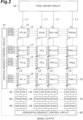
- FIG. 2 illustrates a configuration example of N ⁇ M pixel circuits 13 arranged in N rows and M columns (M and N are integers equal to or greater than 2), and the pixel circuit 13 in the i-th column and the j-th row (i is an integer equal to or greater than 1 and equal to or less than M, and j is an integer equal to or greater than 1 and equal to or less than N) is expressed as "P(i, j)" (similarly described in the following description).
- the pixel driver 32 is connected in parallel to the control electrodes G 1 to G 4 and G D of the N pixel circuits 13 in the respective columns via a wiring portion L1.
- the first to the fourth control pulses G(1) to G(4) and the fifth control pulse G(D) can be simultaneously applied from the pixel driver 32 to all the pixel circuits 13 via the M wiring portions L1 connected to the pixel circuits 13 of the respective columns.
- the signal readout circuit 15 includes a vertical readout control circuit 41, a horizontal readout control circuit 42, and a current source load (CSL) 43, a program gain amplifier (PGA) 44, and an analogto-digital converter (ADC) 45 provided for each column of the pixel circuit 13 in the number of sets (two sets in the present embodiment) corresponding to the number of charge readout regions of each group divided into N D .
- CSL current source load
- PGA program gain amplifier
- ADC analogto-digital converter
- the vertical readout control circuit 41 is electrically connected to the M pixel circuits 13 in each row via wiring portions L2 whose number is twice the number of divisions N D of the groups of the charge readout regions and simultaneously outputs selection signals SL1 and SL2 and reset signals RT1 and RT2 to the M pixel circuits 13 in each row via the wiring portions L2.
- the selection signals SL1 and SL2 are electric signals for selecting a group from which the detection signals are to be read out among the plurality of divided groups of the charge readout regions
- the reset signals RT1 and RT2 are electric signals for resetting charges of the charge readout regions of one group among the plurality of divided groups of the charge readout regions.
- the selection signals SL1 and SL2 and the reset signals RT1 and RT2 output to the j-th row pixel circuits 13 are expressed as "SL1(j)", “SL2(j)”, “RT1(j)”, and “RT2(j)”, respectively (similarly described in the following description).
- One set of circuits including the CSL 43, the PGA 44, and the ADC 45 is sequentially connected in series to the N pixel circuits 13 in the corresponding column via the wiring portion L3.
- the CSL 43 is a current source that supplies currents flowing from the voltage detection units 26 1 to 26 4 of the pixel circuits 13 belonging to the row selected by the vertical readout control circuit 41 to the wiring portion L3.
- the PGA 44 is a circuit that detects detection signals generated by supply of the currents by the CSL 43 from the voltage detection units 26 1 to 26 4 of the pixel circuits 13 selected by the vertical readout control circuit 41 and amplifies the detection signals.
- the ADC 45 is a circuit that converts the detection signals amplified by the PGA 44 into digital signals.
- the horizontal readout control circuit 42 is a circuit for collecting the two detection signals output from the two ADCs 45 provided corresponding to columns of the pixel circuits 13 for each row and outputting them to the arithmetic circuit 17.
- FIG. 3 is a view illustrating a connection relationship between the pixel circuits 13 and the ADCs 45
- FIG. 4 is a circuit diagram illustrating a detailed configuration of the pixel circuit 13.
- the CSL 43 and the PGA 44 are not illustrated for convenience of description.
- the pixel circuit 13 includes reset transistors 51, amplification transistors 52, and selection transistors (switches) 53 constituting the voltage detection units 26 1 to 26 4 for each of the four charge readout regions 22 1 to 22 4 .
- the reset transistors 51 are connected between the charge readout regions 22 1 to 22 4 and a reset potential V RT , and have a role of resetting the charges accumulated in the charge readout regions 22 1 to 22 4 in response to application of any of the reset signals RT1 and RT2 from the vertical readout control circuit 41.
- the amplification transistors 52 have gates electrically connected to the charge readout regions 22 1 to 22 4 , drains supplied with a potential VDDSF, and sources connected to one of the two wiring portions L3 via the selection transistors 53.
- one of the selection signals SL1 and SL2 from the vertical readout control circuit 41 is applied to gates of the selection transistors 53, and the selection transistors 53 have drains connected to the sources of the amplification transistors 52, and the sources connected to one of the two wiring portions L3. If the selection signals SL1 and SL2 are applied to the gates of the selection transistors 53 in the transistors 52 and 53, connections between the sources of the amplification transistors 52 and the wiring portions L3 are turned on. As a result, a source follower circuit is formed by the amplification transistors 52 and the CSL 43 ( FIG.
- the two reset transistors 51 connected to the charge readout regions 22 1 and 22 2 of one group are configured such that one reset signal RT1 is applied, and the two reset transistors 51 connected to the charge readout regions 22 3 and 22 4 of the other group are configured such that the other reset signal RT2 is applied.
- the two selection transistors 53 connected to the charge readout regions 22 1 and 22 2 of one group are configured such that one selection signal SL1 is applied, and the two selection transistors 53 connected to the charge readout regions 22 3 and 22 4 of the other group are configured such that the other selection signal SL2 is applied.
- the two selection transistors 53 connected to the charge readout regions 22 1 and 22 2 of one group are configured to be separately connected to the two wiring portions L3, and the two selection transistors 53 connected to the charge readout regions 22 3 and 22 4 of the other group are configured to be separately connected to the two wiring portions L3.
- two detection signals V O1 (i) and V O2 (i) can be simultaneously (in parallel) output to the ADCs 45 from two charge readout regions (charge readout regions 22 1 and 22 2 or charge readout regions 22 3 and 22 4 ) belonging to the selected group via the two wiring portions L3.
- FIG. 5 is a view indicating timings of exposure operation and timings of signal readout operation for each subframe period obtained by temporally dividing the frame period for each of the charge readout regions 22 1 to 22 4 corresponding to the control electrodes G 1 to G 4
- FIG. 6 is a timing chart indicating timings of electric signals output from the vertical readout control circuit 41 for each row of the pixel circuits 13 and control pulses output from the pixel driver 32 in association with the operation indicated in FIG. 5
- FIG. 5 is a view indicating timings of exposure operation and timings of signal readout operation for each subframe period obtained by temporally dividing the frame period for each of the charge readout regions 22 1 to 22 4 corresponding to the control electrodes G 1 to G 4
- FIG. 6 is a timing chart indicating timings of electric signals output from the vertical readout control circuit 41 for each row of the pixel circuits 13 and control pulses output from the pixel driver 32 in association with the operation indicated in FIG. 5
- FIG. 5 is a view indicating timings of
- a period occupying one frame period T F is represented by being divided into a plurality of rectangular blocks whose size in the horizontal direction corresponds to a length of a period, and each rectangular block is assigned with identification indicating a type of processing to be controlled by the pixel driver 32 and the signal readout circuit 15.
- a period during which the exposure operation is executed is indicated by a white rectangular block
- a period during which the charge reset operation is executed is indicated by a shaded rectangular block denoted by a reference sign P RST
- a period during which the signal readout operation is executed is indicated by a shaded rectangular block denoted by a reference sign P R .
- subframe periods SF(1) and SF(3) are set for the charge readout regions 22 1 and 22 2 of one of the groups that are grouped, and subframe periods SF(2) and SF(4) parallel to the subframe periods SF(1) and SF(3) are set for the charge readout regions 22 3 and 22 4 of the other of the groups that are grouped.
- the exposure operation of transferring the charges from the photoelectric conversion region 21 to the charge readout regions 22 1 and 22 2 is executed under the control of the pixel driver 32, and thereafter, the signal readout operation of reading out the detection signals from the charge readout regions 22 1 and 22 2 is executed under the control of the signal readout circuit 15.
- the exposure operation for the charge readout regions 22 1 and 22 2 is executed under the control of the pixel driver 32, and thereafter, the signal readout operation for the charge readout regions 22 1 and 22 2 is executed under the control of the signal readout circuit 15. Furthermore, in the subframe period SF(2) that starts at the same time as the subframe period SF(1), the exposure operation for the charge readout regions 22 3 and 22 4 is executed under the control of the pixel driver 32, and thereafter, the signal readout operation for the charge readout regions 22 3 and 22 4 is executed under the control of the signal readout circuit 15.
- the exposure operation for the charge readout regions 22 3 and 22 4 is executed under the control of the pixel driver 32, and thereafter, the signal readout operation for the charge readout regions 22 3 and 22 4 is executed under the control of the signal readout circuit 15.
- a length T R of the period P R of the signal readout operation controlled to be executed in each of the subframe periods SF(1) to SF(4) is set to a period determined by the number of rows of the pixel circuits 13 and performance of the signal readout function, and a length of a period of the exposure operation controlled to be executed in each of the subframe periods SF(1) to SF(4) is set to a length corresponding to a delay period of each of the first to the fourth control pulses G(1) to G(4) applied in each period.
- a reference sign W k (k is an integer equal to or greater than 1) is also written in each control pulse G(X) (X is an integer of any one of 1, 2, 3, and 4) indicated in FIG. 6 , and the number "k" attached to the reference sign W k corresponds to the delay period of the control pulse G(X) with respect to the pulsed light L P .
- the reset signal RT1 output for resetting the charge readout regions 22 1 and 22 2 of one group is sequentially turned on for each row.
- the control pulses G(1) and G(2) for exposure operation control of the charge readout regions 22 1 and 22 2 of one group are repeatedly turned on so as to set the delay periods for the pulsed light L P to be constant.
- the control pulse G(1) is set to a timing specified by the reference numeral W 1
- the control pulse G(2) is set to a timing specified by the reference numeral W 2 .
- the selection signal SL1 output for selection at the time of signal readout of the charge readout regions 22 1 and 22 2 of one group is sequentially turned on for each row, and at the same time, the reset signal RT1 for resetting the charges of the charge readout regions 22 1 and 22 2 is sequentially turned on for each row at the timing after the selection signal SL1 is turned on.
- control pulses G(3) and G(4) for exposure operation control of the charge readout regions 22 3 and 22 4 of the other group are repeatedly turned on so as to set the delay periods for the pulsed light L P to be constant.
- the control pulse G(3) is set to a timing specified by the reference numeral W 3
- the control pulse G(4) is set to a timing specified by the reference numeral W 4 .
- the selection signal SL2 output for selection at the time of signal readout of the charge readout regions 22 3 and 22 4 of the other group is sequentially turned on for each row, and at the same time, the reset signal RT2 for resetting the charges of the charge readout regions 22 3 and 22 4 is sequentially turned on for each row at the timing after the selection signal SL2 is turned on.
- the control pulses G(1) and G(2) for exposure operation control of the charge readout regions 22 1 and 22 2 of one group are repeatedly turned on so as to set the delay periods for the pulsed light L P to be constant.
- the control pulse G(1) is set to a timing specified by the reference numeral W 7
- the control pulse G(2) is set to a timing specified by the reference numeral W 8 .
- the signal readout operation is executed in the same manner as the control in the subframe period SF(1).
- the exposure operation and the signal readout operation are controlled similarly to the control in the subframe period SF(2), and the delay periods of the control pulses G(3) and G(4) at the time of the exposure operation are respectively set to periods specified by the reference numerals W 5 and W 6 .
- lengths T EX1 to T EX4 of the periods of the exposure operation in the subframe periods SF(1) to SF(4) are set to different periods corresponding to lengths of the delay periods of the control pulses G(1) to G(4) set in the respective kinds of exposure operation, and the subframe period is set to be longer as the delay period is longer.
- the delay period in the subframe period SF(2) is longer than the delay period in the subframe period SF(1) by about twice the duration T 1
- the delay period in the subframe period SF(4) is longer than the delay period in the subframe period SF(2) by about twice the duration T 1
- the delay period in the subframe period SF(3) is longer than the delay period in the subframe period SF(4) by about twice the duration T 1 .
- timings of the control pulses G(1) to G(4) and the pulsed light L P in the subframe periods SF(1) to SF(4) within one frame period are set by the light source driver 31 and the pixel driver 32 (a light source control step and a charge transfer control step).
- the delay periods of the control pulses G(1) to G(4) to be controlled for each group of the charge readout regions 22 1 to 22 4 are maintained constant, the delay periods of the control pulses G(1) to G(4) to be controlled are set to different periods between the subframe periods SF(1) to SF(4), and the lengths of the subframe periods SF(1) to SF(4) are set so as to become longer as the delay periods of the control pulses G(1) to G(4) to be controlled become longer.
- the detection signals are read out from the charge readout regions 22 1 to 22 4 for each row of the pixel circuits 13 by the signal readout circuit 15 via the voltage detection units 26 1 to 26 4 of the respective pixel circuits 13, and the detection signals are converted into digital values and then output to the arithmetic circuit 17 (signal readout step).
- the detection signals are read out in parallel from the two charge readout regions 22 1 and 22 2 or the two charge readout regions 22 3 and 22 4 belonging to the group to be controlled at different timings for each of the subframe periods SF(1) to SF(4) by the signal readout circuit 15.
- the arithmetic circuit 17 calculates distance information for each pixel in units of one frame period (distance calculation step). However, the arithmetic circuit 17 may calculate the distance information by averaging calculation results for each of a plurality of frame periods.
- the arithmetic circuit 17 calculates difference values S 1-3 (1) and S 2-4 (1) and difference values S 1-3 (2) and S 2-4 (2) using the following Formula (1) to Formula (4).
- These calculation formulas also include weighting calculation according to the lengths of the subframe periods SF(1) to SF(4), that is, the number of applied control pulses G(1) to G(4).
- S 1 ⁇ 3 1 16 ⁇ 1 / 1 ⁇ S 1 1 ⁇ 1 / 4
- S 3 1 S 2 ⁇ 4 1 16 ⁇ 1 / 1 ⁇ S 2 1 ⁇ 1 / 4 S 4 1
- S 1 ⁇ 3 2 ⁇ 16 ⁇ 1 / 16 ⁇ S 1 2 ⁇ 1 / 9
- S 2 ⁇ 4 2 ⁇ 16 ⁇ 1 / 16 ⁇ S 2 2 ⁇ 1 / 9 S 4 2
- the arithmetic circuit 17 calculates distance information using a calculation method disclosed in WO 2019/078366 A . Specifically, the arithmetic circuit 17 calculates values of distance data validity determination signals S A (1) and S A (2) using the following Formulas (5) and (6) based on the difference values S 1-3 (1) , S 2-4 (1) , S 1-3 (2) , and S 2-4 (2) .
- S A 1 S 1 ⁇ 3 1 + S 2 ⁇ 4 1
- S A 2 S 1 ⁇ 3 2 + S 2 ⁇ 4 2
- the arithmetic circuit 17 calculates values of a first distance calculation reference signal X R (1) and a second distance calculation reference signal Y R (1) using the following Formulas (7) and (8).
- X R 1 1 ⁇ S 1 ⁇ 3 1 / S A 1
- Y R 1 2 ⁇ S 2 ⁇ 4 1 /S A 1
- the arithmetic circuit 17 calculates values of distance calculation reference signals X R (B) , Y R (B) , X R (2) , and Y R (2) using the following Formulas (9) to (12).
- the arithmetic circuit 17 selects a value to be referred to for distance calculation from among the distance calculation reference signals X R (1) , X R (B) , and X R (2) and the distance calculation reference signals Y R (1) , Y R (B) , and Y R (2) .
- the value of the distance data validity determination signal S A (1) is equal to or greater than the threshold Th 1
- one of the distance calculation reference signals X R (1) and Y R (1) is selected according to the values of the distance calculation reference signals X R (1) and Y R (1) .
- one of the distance calculation reference signals X R (2) and Y R (2) is selected according to the values of the distance calculation reference signals X R (2) and Y R (2) .
- any one of the distance data validity determination signals S A (1) and S A (2) is equal to or greater than the threshold Th 1
- one of the distance calculation reference signals X R (B) and Y R (B) is selected according to the values of the distance calculation reference signals X R (B) and Y R (B) .
- a distance of the object S is calculated by the arithmetic circuit 17 based on the distance calculation reference signals X R (1) , X R (B) , X R (2) , Y R (1) , Y R (B) , and Y R (2) selected with respect to the corresponding pixel, the calculation result is reflected in the distance information of the corresponding pixel, and the distance image including the distance information of each pixel is generated and output.
- the pulsed light L P is periodically and repeatedly generated from the light source 11 within the periodic frame period T F , and time windows for the first to the fourth charge readout regions 22 1 to 22 4 are set within the frame period T F while being delayed from the generation of the pulsed light L P , and charges are transferred from the photoelectric conversion region 21 of the pixel circuit 13 to the first to the fourth charge readout regions 22 1 to 22 4 within the respective time windows. Furthermore, detection signals corresponding to the first to the fourth charge amounts accumulated in the first to the fourth charge readout regions 22 1 to 22 4 are read out from the first to the fourth charge readout regions 22 1 to 22 4 of the pixel circuit 13.
- the detection signals are read out at different timings for each group of the charge readout regions 22 1 to 22 4 divided into two.
- the detection signals can be read out at different timings between one group of the charge readout regions 22 1 to 22 4 for which a time window corresponding to a timing of reflected light L R of pulsed light L P generated at a short distance is set and the other group of the charge readout regions 22 1 to 22 4 for which a time window corresponding to a timing of reflected light L R of pulsed light L P generated at a long distance is set, and the exposure period of the reflected light L R can be changed between the two groups of the charge readout regions 22 1 to 22 4 within the limited frame period T F .
- the period of the signal readout operation of a certain group can be set to the period of the exposure operation of another group, so that the period of the exposure operation for each group can be lengthened. This results in making it possible to generate an image signal with improved distance resolution even in a case where the object S in a wide distance range is to be measured.
- the pixel driver 32 performs control so as to maintain substantially constant delay periods with respect to the generation timing of the pulsed light L P of the control pulses G(1) to G(4) to be applied corresponding to the group of the charge readout regions 22 1 to 22 4 within the subframe periods SF(1) to SF(4) sandwiched between the timings of the signal readout processing of the two groups obtained by dividing the charge readout regions 22 1 to 22 4 into two.
- the detection signals are read out from the respective groups of the charge readout regions 22 1 to 22 4 after an elapse the subframe periods SF(1) to SF(4) for which the delay periods with respect to the timings of the pulsed light L P are set to be substantially constant.
- an exposure period according to a distance to be measured can be set, so that distance resolution can be further improved.
- the signal readout circuit 15 includes a plurality of wiring portions L3 electrically connected to the plurality of charge readout regions 22 1 to 22 4 included in the groups of the charge readout regions 22 1 to 22 4 divided into two via switches, and is configured to read out detection signals in parallel from the plurality of charge readout regions 22 1 to 22 4 via the plurality of wiring portions L3 by turning on the switches at the signal readout timings.
- the detection signals can be read out in parallel from the respective groups of the charge readout regions 22 1 to 22 4 divided into two, so that efficiency of the signal readout operation can be improved. This results in making it possible to secure the exposure period of the reflected light L R within the limited frame period T F , so that an image signal with further improved distance resolution can be generated.
- the pixel driver 32 sets the delay periods of the control pulses G(1) to G(4) to different periods between the groups of the charge readout regions 22 1 to 22 4 divided into two, and the signal readout circuit 15 sets the timings of the signal readout operation for each group of the charge readout regions divided into two such that the lengths of the subframe periods SF(1) to SF(4) increase as the delay periods increase.
- the exposure period of one group of the charge readout regions 22 1 to 22 4 for which a time window corresponding to a timing of reflected light L R of pulsed light L P generated at a long distance is set can be made longer than the exposure period of the other group of the charge readout regions 22 1 to 22 4 for which a time window corresponding to a timing of reflected light L R of pulsed light L P generated at a short distance is set. This results in making it possible to generate an image signal with further improved distance resolution even in a case where the object S in a wide distance range is to be measured.
- the distance image sensor 10 includes a plurality of pixel circuits 13 arranged in a plurality of rows, and the signal readout circuit 15 performs control such that charge accumulation periods of the first to the fourth charge readout regions 22 1 to 22 4 coincide with each other between rows of the plurality of pixel circuits 13.
- the signal readout circuit 15 performs control to shift timings of the signal readout operation for each group of the charge readout regions 22 1 to 22 4 between the rows of the plurality of pixel circuits 13.
- the signal readout circuit 15 can be shared among the rows of the plurality of pixel circuits 13, so that the configuration of the distance image sensor 10 can be simplified.
- FIG. 8 indicates timings of exposure operation and signal readout operation for each subframe period to be controlled by a distance image sensor according to a comparative example.
- This comparative example has a configuration similar to that of the pixel circuit 13 of the above embodiment, and one frame period T F is divided into two subframe periods SF(1) and SF(2), and a timing of the signal readout operation (corresponding to the rectangular block indicated by hatching) is set at the end of each of the subframe periods SF(1) and SF(2).
- the delay periods of the control pulses G(1) to G(4) are set to be constant at the timings of the exposure operation (corresponding to the rectangular block indicated by white) in the subframe periods SF(1) and SF(2), and in the signal readout operation, the operation is performed so as to read out every two detection signals in parallel from the charge readout regions 22 1 to 22 4 at the same timings of the signal readout operation.
- T F 2 ⁇ T R + 1 + 4 ⁇ T A 0
- a ratio of the period T A,max of the exposure operation in the subframe period SF(3) in the present embodiment is calculated on the premise of a control state indicated in FIG. 5 .
- charge readout regions 22 1 to 22 4 are provided in the pixel circuit 13, but any number of charge readout regions (hereinafter, a configuration of M 1 (M 1 is an integer equal to or greater than 2) charge readout regions is also referred to as a "M 1 tap") may be provided as long as the number is two or more.
- M 1 is an integer equal to or greater than 2
- M 1 tap any number of charge readout regions
- the control electrodes and the voltage detection units are provided corresponding to the number M 1 of charge readout regions
- the pixel driver 32 generates the first to the M 1 -th control pulses G(1) to G(M 1 ) corresponding to the number M 1 of the control electrodes
- the signal readout circuit 15 reads out the first to the M 1 -th detection signals from the charge readout regions
- the arithmetic circuit 17 calculates distance information based on the first to the M 1 -th detection signals read out from the respective charge readout regions by the signal readout circuit 15.
- FIG. 9 is a circuit diagram illustrating a detailed configuration of the pixel circuit 13 of the modification having the 6-tap configuration.
- the pixel circuit 13 is provided with the first to the sixth charge readout regions 22 1 to 22 6 , the first to the sixth control electrodes G 1 to G 6 , and the first to the sixth voltage detection units 26 1 to 26 6 .
- the first to the sixth charge readout regions 22 1 to 22 6 are grouped into two groups of the first to the third charge readout regions 22 1 to 22 3 and the fourth to the sixth charge readout regions 22 4 to 22 6 , the first to the third charge readout regions 22 1 to 22 3 are connected in parallel to the three wiring portions L3 via the first to the third voltage detection units 26 1 to 26 3 , respectively, and the fourth to the sixth charge readout regions 22 4 to 22 6 are connected in parallel to the three wiring portions L3 via the fourth to the sixth voltage detection units 26 4 to 26 6 , respectively.
- the pixel driver 32 of the present modification performs control so as to maintain the delay periods of the first to the sixth control pulses G(1) to G(6) within the subframe period substantially constant for each group of the charge readout regions 22 1 to 22 6 , similarly to the above-described embodiment.
- the signal readout circuit 15 sets a period of exposure operation for each group of the charge readout regions 22 1 to 22 6 in the subframe period, and sets a timing of parallel signal readout operation for each group of the charge readout regions 22 1 to 22 6 in the subframe period.
- the first to the sixth charge readout regions 22 1 to 22 6 may be divided into three groups as in the configuration illustrated in FIG. 10 .
- the first to the sixth charge readout regions 22 1 to 22 6 are grouped into three groups: the first and the second charge readout regions 22 1 and 22 2 , the third and the fourth charge readout regions 22 3 and 22 4 , and the fifth and the sixth charge readout regions 22 5 and 22 6 .
- first and the second charge readout regions 22 1 and 22 2 are connected in parallel to the two wiring portions L3 respectively via the first and the second voltage detection units 26 1 and 26 2
- the third and the fourth charge readout regions 22 3 and 22 4 are connected in parallel to the two wiring portions L3 respectively via the third and the fourth voltage detection units 26 3 and 26 4
- the fifth and the sixth charge readout regions 22 5 and 22 6 are connected in parallel to the two wiring portions L3 respectively via the fifth and the sixth voltage detection units 26 5 and 26 6 .
- FIG. 11 is a circuit diagram illustrating a detailed configuration of the pixel circuit 13 of another modification having the 3-tap configuration.
- the pixel circuit 13 is provided with the first to the third charge readout regions 22 1 to 22 3 , the first to the third control electrodes G 1 to G 3 , and the first to the third voltage detection units 26 1 to 26 3 .
- the first to the third charge readout regions 22 1 to 22 3 are grouped into three groups: the first charge readout region 22 1 , the second charge readout region 22 2 , and the third charge readout region 22 3 , and the first to the third charge readout regions 22 1 to 22 3 are connected to one wiring portion L3 respectively via the first to the third voltage detection units 26 1 to 26 3 .
- the pixel driver 32 of the present modification performs control so as to maintain delay periods of the first to the third control pulses G(1) to G(3) within the subframe period substantially constant for each group of the charge readout regions 22 1 to 22 3 .
- the signal readout circuit 15 sets a period of exposure operation for each group of the charge readout regions 22 1 to 22 3 in the subframe period and sets a timing of signal readout operation for each group of the charge readout regions 22 1 to 22 3 in the subframe period.
- the distance image sensor 10 may perform control such that control timings are exchanged between groups of the charge readout regions in two consecutive one frame periods.
- FIG. 12 indicates timings of the exposure operation and the signal readout operation for each subframe period to be controlled by the distance image sensor according to the modification.
- the pixel driver 32 and the signal readout circuit 15 set timings of the exposure operation and the signal readout operation for one group including the charge readout regions 22 1 and 22 2 and the other group including the charge readout regions 22 3 and 22 4 in the subframe periods SF(1a) to SF(4a), similarly to the above-described embodiment.
- the pixel driver 32 and the signal readout circuit 15 of the present modification exchange setting targets of respective timings in the subframe periods SF(1b) to SF(4b) between the one group including the charge readout regions 22 1 and 22 2 and the other group including the charge readout regions 22 3 and 22 4 .
- the pixel driver 32 exchanges setting of the delay periods of the control pulses G(1) and G(2) set for the one group including the charge readout regions 22 1 and 22 2 and setting of the delay periods of the control pulses G(3) and G(4) set for the other group including the charge readout regions 22 3 and 22 4 .
- the signal readout circuit 15 exchanges setting of the timing of the signal readout operation for the one group including the charge readout regions 22 1 and 22 2 and setting of the timing of the signal readout operation for the other group including the charge readout regions 22 3 and 22 4 .
- the pixel driver 32 and the signal readout circuit 15 set a first subframe period SF(1b) of the frame period Frame1b to a timing overlapping with the last subframe period SF(3a) of the frame period Frame1a. This makes it possible to more efficiently secure a period of the exposure operation.
- the arithmetic circuit 17 calculates difference values S 1-3 (1) (Frame1a), S 2-4 (1) (Frame1a), S 1-3 (2) (Frame1a), and S 2-4 (2) (Frame1a) based on detection signals S 1 (1) to S 4 (1) and S 1 (2) to S 4 (2) acquired by the signal readout operation in a certain one frame period Frame1a, similarly to the above embodiment.
- the arithmetic circuit 17 calculates difference values S 1-3 (1) (Frame1b), S 2-4 (1) (Frame1b), S 1-3 (2) (Frame1b), and S 2-4 (2) (Frame1b) by using the following Formulas (13) to (16) based on detection signals S 1 (1) to S 4 (1) and S 1 (2) to S 4 (2) acquired by the signal readout operation in the immediately following one frame period Frame1b.
- the arithmetic circuit 17 calculates a moving average of the difference values between the two frame periods Frame1a and Frame1b by the following Formulas (17) to (20).
- S 1 ⁇ 3 1 S 1 ⁇ 3 1 Frame1a + S 1 ⁇ 3 1 Frame1b / 2
- S 2 ⁇ 4 1 S 2 ⁇ 4 1 Frame1a + S 2 ⁇ 4 1 Frame1b / 2
- S 1 ⁇ 3 2 S 1 ⁇ 3 2 Frame1a + S 1 ⁇ 3 2 Frame1b / 2
- S 2 ⁇ 4 2 S 2 ⁇ 4 2 Frame1a + S 2 ⁇ 4 2 Frame1b / 2
- the arithmetic circuit 17 calculates a distance based on the moving average of the four difference values for each frame period and generates a distance image including distance information reflecting the distance.
- the present modification it is possible to generate an image signal with improved distance resolution even in a case where the object S in a wide distance range is to be measured.
- the distance is calculated by the moving average during the frame period, so that it is possible to cancel or reduce influence of nonlinear variation in a gain between the plurality of pixel circuits 13 that outputs the detection signals.
- the subframe period is set for each group of the charge readout regions of the pixel circuit 13.
- the pixel driver 32 and the signal readout circuit 15 according to the modification may divide the pixel circuits 13 of N rows into groups in units of rows and further allocate different subframe periods to each of the divided row groups.
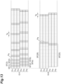
- FIG. 13 is a view indicating timings of exposure operation and timings of signal readout operation for each subframe period obtained by temporally dividing a frame period in the present modification.
- the pixel driver 32 and the signal readout circuit 15 allocate different subframe periods to the group of the charge readout regions for each of the group Gr1 of the pixel circuits 13 in the odd rows and the group Gr2 of the pixel circuits 13 in the even rows, and set periods T R of the signal readout operation at different timings at the ends of the subframe periods for each of the groups Gr1 and Gr2.
- subframe periods SF(1), SF(3), and SF(5) are set for the charge readout regions 22 1 to 22 3 of the pixel circuits 13 belonging to the group Gr1
- subframe periods SF(2), SF(4), and SF(6) are set for the charge readout regions 22 4 to 22 6 of the pixel circuits 13 belonging to the group Gr1 in parallel to the subframe periods SF(1), SF(3), and SF(5).
- a subframe period SF(26) is set for the charge readout regions 22 1 to 22 3 of the pixel circuits 13 belonging to the group Gr2, and in parallel to the subframe period SF(26), a subframe period SF(25) is set for the charge readout regions 22 4 to 22 6 of the pixel circuits 13 belonging to the group Gr2.
- a total of 32 subframe periods can be set within one frame period for even rows and odd rows.
- a selection circuit that selects consecutive control pulses G(1) to G(6) and G(D) to be applied from the pixel driver 32 to the pixel circuits 13 of each row at a desired timing within a subframe period for each of the row groups Gr1 and Gr2 and applies the selected control pulses to the control electrodes G 1 to G 6 and G D .
- the pixel driver 32 and the signal readout circuit 15 may operate to exchange setting of the subframe period for each of the row groups Gr1 and Gr2 as indicated in FIG. 13 between two consecutive frame periods.
- the exposure period can be more efficiently changed within a limited frame period. As a result, it becomes easy to generate an image signal with improved distance resolution.
- the pixel driver 32 performs control to perform so-called global exposure so that charge accumulation periods of the first to the fourth charge readout regions 22 1 to 22 4 coincide with each other between the rows of the plurality of pixel circuits 13.
- the pixel driver 32 may perform control so as to perform so-called rolling exposure so as to sequentially shift the accumulation periods of the first to the fourth charge readout regions 22 1 to 22 4 between the rows of the plurality of pixel circuits 13 every constant period.
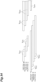
- FIG. 14 indicates timings of the period of the exposure operation in each row of the pixel circuits 13 in a case where control by the pixel driver 32 indicated in FIG. 5 and FIG. 6 is set so that rolling exposure is performed. In FIG.
- a horizontal direction corresponds to an elapse of time, and the timings of the exposure period of each row of the pixel circuits are indicated in the vertical direction.
- control is performed such that a period T EX1 of the exposure operation in the subframe period SF(1) is sequentially shifted between the pixel circuits 13 in the first to the fourth consecutive rows every certain period.
- periods T EX2 and T EX3 of the exposure operation in the subframe periods SF(2) and SF(3) are also controlled to be sequentially shifted between the pixel circuits 13 in the first to the fourth consecutive rows every certain period.
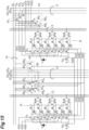
- FIG. 15 extracts a circuit configuration around the pixel circuit 13 of some specific rows in the distance image sensor 10.
- the pixel circuit 13 has a 6-tap configuration illustrated in FIG. 9 .
- Switch circuits 61, 63, and 65 are provided in common to two adjacent pixel circuits 13 in the same row.
- the switch circuit 61 includes six switch elements 67 1 , 69 1 , 67 3 , 69 3 , 67 5 , and 69 5 .
- the switch elements 67 1 , 69 1 , 67 3 , 69 3 , 67 5 , and 69 5 are, for example, MOS transistors.
- the switch element 67 1 is connected between the pixel driver 32 and the control electrodes G 1 of the two pixel circuits 13 for each row, has a source connected to the pixel driver 32 via the wiring portion L1, a drain connected to the control electrodes G 1 of the two pixel circuits 13, and a gate connected to the pixel driver 32 via the wiring portion L4 provided for each row.
- the switch element 69 1 is connected between the control electrodes G 1 of the two pixel circuits 13 and a fixed potential (in the present embodiment, the ground potential), has a drain connected to the control electrodes G 1 of the two pixel circuits 13, has a source connected to the fixed potential, and has a gate connected to the pixel driver 32 via the wiring portion L4 provided for each row.
- the switch elements 67 3 , 69 3 , 67 5 , and 69 5 have a similar configuration.
- the switch element 67 3 is connected between the pixel driver 32 and the control electrodes G 3 of the two pixel circuits 13 for each row
- the switch element 69 3 is connected between the control electrodes G 3 of the two pixel circuits 13 and the fixed potential.
- the switch element 67 3 and the switch element 69 3 selectively apply either a control pulse DG 3 for the control electrode G 3 supplied from the pixel driver 32 or the fixed potential to the control electrodes G 3 of the two pixel circuits 13 based on the selection signals S R and U R supplied from the pixel driver 32.
- the switch element 67 5 is connected between the pixel driver 32 and the control electrodes G 5 of the two pixel circuits 13 for each row, and the switch element 69 5 is connected between the control electrodes G 5 of the two pixel circuits 13 and the fixed potential.
- the switch element 67 5 and the switch element 69 5 selectively apply either a control pulse DG 5 for the control electrode G 5 supplied from the pixel driver 32 or the fixed potential to the control electrodes G 5 of the two pixel circuits 13 based on the selection signals S R and U R supplied from the pixel driver 32.
- the switch circuit 63 includes six switch elements 67 2 , 69 2 , 67 4 , 69 4 , 67 6 , and 69 6 having a configuration similar to that of the switch circuit 61.
- the switch element 67 2 and the switch element 69 2 selectively apply either a control pulse DG 2 for the control electrode G 2 or the fixed potential to the control electrodes G 2 of the two pixel circuits 13 based on the selection signals S R and U R supplied from the pixel driver 32.
- the switch element 67 4 and the switch element 69 4 selectively apply either a control pulse DG 4 for the control electrode G 4 or the fixed potential to the control electrodes G 4 of the two pixel circuits 13 based on the selection signals S R and U R supplied from the pixel driver 32.
- the switch element 67 6 and the switch element 69 6 selectively apply either a control pulse DG 6 for the control electrode G 6 or the fixed potential to the control electrodes G 6 of the two pixel circuits 13 based on the selection signals S R and U R supplied from the pixel driver 32.
- the switch circuit 65 includes two switch elements 67 D and 69 D having a configuration similar to that of the switch circuit 61.
- the switch element 67 D and the switch element 69 D selectively apply either a control pulse DG D for the control electrode G D or a fixed potential (positive potential in the present embodiment) to the control electrodes G D of the two pixel circuits 13 based on the selection signals S R and U R supplied from the pixel driver 32.
- FIG. 16 and FIG. 17 are timing charts indicating control timings of the exposure operation in the above modification
- FIG. 16 indicates control timings at a first generation timing of the pulsed light L P periodically generated within the subframe period of the subframe period SF(1) indicated in FIG. 13
- FIG. 17 indicates control timings at the first generation timing of the pulsed light L P immediately after the subframe period SF(6) indicated in FIG. 13 .
- control timings timings of control pulses DG 1 to DG 6 and DG D supplied from the pixel driver 32, selection signals S R (o) and U R (o) supplied to the pixel circuits 13 in the odd rows, control pulses G(1)(o) to G(6)(o) and G(D)(o) applied to the pixel circuits 13 in the odd rows, selection signals S R (e) and U R (e) supplied to the pixel circuits 13 in the even rows, and control pulses G(1)(e) to G(6)(e) and G(D)(e) applied to the pixel circuits 13 in the odd rows are indicated.
- the control pulses DG 1 to DG 3 common between the rows supplied from the pixel driver 32 are set to be turned on at any timing specified by the reference numerals W 1 to W 3 and at any timing specified by reference numerals W 76 to W 78 , respectively, and to be turned off at other timings. Furthermore, the control pulse DG D common between the rows supplied from the pixel driver 32 is set to be turned off at timings including timings specified by the reference numerals W 1 to W 3 and timings including timings specified by the reference numerals W 76 to W 78 , and to be turned on in other periods.
- the selection signal S R (o) set in the odd rows is turned on across the timings specified by the reference numerals W 1 to W 3
- the selection signal S R (e) set in the even rows is turned on across the timings specified by the reference numerals W 76 to W 78 .
- the control pulses G(1)(o) to G(3)(o) to be applied to the pixel circuits 13 in the odd rows are set to be turned on at the timings specified by the reference numerals W 1 to W 3
- the control pulse G(D)(o) applied to the pixel circuits 13 in the odd rows is set to be turned off at the timings including the timings specified by the reference numerals W 1 to W 3 .
- control pulses G(1)(e) to G(3)(e) to be applied to the pixel circuits 13 in the even rows are set to be turned on at the timings specified by the reference numerals W 76 to W 78
- control pulses G(D)(e) to be applied to the pixel circuits 13 in the even rows are set to be turned off at the timings including the timings specified by reference numerals W 76 to W 78 .
- the control pulses DG 1 to DG 6 common between the rows supplied from the pixel driver 32 are set to be turned on at any timing specified by reference numerals W 22 to W 27 and at any timing specified by reference numerals W 73 to W 78 , respectively, and to be turned off at other timings.
- the control pulse DG D common between the rows supplied from the pixel driver 32 is set to be turned off at timings including timings specified by the reference numerals W 22 to W 27 and timings including timings specified by the reference numerals W 73 to W 78 , and to be turned on in other periods.
- the selection signal S R (o) set in the odd rows is turned on across the timings specified by the reference numerals W 22 to W 27
- the selection signal S R (e) set in the even rows is turned on across the timings specified by the reference numerals W 73 to W 78 .
- the control pulses G(1)(o) to G(6)(o) applied to the pixel circuits 13 in the odd rows are set to be turned on at the timings specified by the reference numerals W 22 to W 27
- the control pulse G(D)(o) applied to the pixel circuits 13 in the odd rows is set to be turned off at the timings including the timing specified by the reference numerals W 22 to W 27 .
- control pulses G(1)(e) to G(6)(e) applied to the pixel circuits 13 in the even rows are set to be turned on at timings specified by the reference numerals W 76 to W 78 and W 73 to W 75
- control pulse G(D)(e) applied to the pixel circuits 13 in the even rows is set to be turned off at timings including timings specified by the reference numerals W 73 to W 78 .
- control pulses DG 1 to DG 6 and DG D from the pixel driver 32 can be selectively applied for each row of the plurality of pixel circuits 13. This results in making it possible to control the charge accumulation periods of the charge readout regions for each row of the plurality of pixel circuits 13, so that it becomes easy to generate an image signal with improved distance resolution.
- the charge transfer control unit preferably maintains the delay periods of the control pulses with respect to the generation timings to be applied corresponding to the group of the charge readout regions to be substantially constant within the subframe period sandwiched between the readout timings of the respective groups of the charge readout regions divided into N.
- the detection signals are read out from each group of the charge readout regions after an elapse of the subframe period for which the delay periods with respect to the timing of the pulsed light are set to be substantially constant.
- the signal readout unit also preferably includes a plurality of signal lines respectively electrically connected to the plurality of charge readout regions included in the group of the charge readout regions divided into N via a switch, and by turning on the switch at the readout timings, preferably reads out the detection signals in parallel from the plurality of charge readout regions via the plurality of signal lines.
- the detection signals can be read out in parallel from each of the groups of the charge readout regions divided into N, so that efficiency of readout processing can be improved. This results in making it possible to secure an exposure period of the reflected light within the limited frame period, so that an image signal with further improved distance resolution can be generated.
- the charge transfer control unit also preferably sets the delay periods of the control pulses to different periods between the groups of the charge readout regions divided into N, and the signal readout unit preferably sets the readout timings for each group of the charge readout regions divided into N such that the subframe period becomes longer as the delay period is longer.
- the exposure period of the group of charge readout regions for which a time window corresponding to a timing of reflected light of pulsed light generated at a long distance is set can be made longer than the exposure period of the group of charge readout regions for which a time window corresponding to a timing of reflected light of pulsed light generated at a short distance is set. This results in making it possible to generate an image signal with further improved distance resolution even in a case where an object in a wide distance range is to be measured.
- the charge transfer control unit preferably performs setting to exchange the delay periods of the control pulses with respect to the generation timing to be applied corresponding to one group of the charge readout regions in one frame period and the delay periods of the control pulses with respect to the generation timing to be applied corresponding to another group of the charge readout regions in one frame period, in a frame period immediately after the one frame period.
- the signal readout unit also preferably performs setting to exchange the readout timings related to one group of the charge readout regions and the readout timings related to another group of the charge readout regions in one frame period, in a frame period immediately after the one frame period. According to this, it is possible to read out the detection signals from the groups after reducing deviation between the exposure period of one group of the charge readout regions and the exposure period of the other group of the charge readout regions in the consecutive frame periods. This results in making it possible to acquire the detection signals for which the exposure period of the reflected light within the limited frame period is secured, so that an image signal with further improved distance resolution can be generated.
- the distance image measuring device also preferably includes a plurality of pixel circuit units arranged in a plurality of rows, and the signal readout unit preferably performs control such that charge accumulation periods of the first to the M-th charge readout regions coincide with each other between rows of the plurality of pixel circuit units.
- the distance image measuring device also preferably includes a plurality of pixel circuit units arranged in a plurality of rows, and the signal readout unit preferably performs control so as to shift charge accumulation periods of the first to the M-th charge readout regions between the rows of the plurality of pixel circuit units.
- a waiting period from exposure to readout in rows of the plurality of pixel circuit units can be shortened, so that noise in detection signals to be read out can be reduced. This results in making it possible to obtain a two-dimensional image signal with less noise.
- switch elements connected between the charge transfer control unit and the control electrodes of the plurality of pixel circuit units for each of the plurality of rows and between the control electrodes and a fixed potential are provided, and the switch elements operate to selectively apply either a control pulse or the fixed potential to the control electrodes in accordance with a selection signal from the outside.
- the control pulse from the charge transfer control unit can be selectively applied for each row of the plurality of pixel circuit units. This results in making it possible to control charge accumulation periods of the charge readout regions for each row of the plurality of pixel circuit units, so that it becomes easy to generate an image signal with improved distance resolution.
Landscapes
- Engineering & Computer Science (AREA)
- Physics & Mathematics (AREA)
- Computer Networks & Wireless Communication (AREA)
- General Physics & Mathematics (AREA)
- Radar, Positioning & Navigation (AREA)
- Remote Sensing (AREA)
- Electromagnetism (AREA)
- Multimedia (AREA)
- Signal Processing (AREA)
- Solid State Image Pick-Up Elements (AREA)
Abstract
Description
- The present disclosure relates to a distance image measuring device and a distance image measuring method for generating a distance image including distance information for each pixel.
- In related art, a device that generates an image signal including distance information using a time of flight of light has been used (see, for example,
Patent Literature 1 below). The device described inPatent Literature 1 below generates pulsed light from a light source, accumulates charges generated in response to the pulsed light in a plurality of charge readout regions in a pixel circuit in different periods set by control pulses, reads out voltages of the plurality of charge readout regions as detection signals and calculates a distance for each pixel based on the detection signals to acquire distance information. - Patent Literature 1:
WO 2019/078366 A - In the above-described device in the related art, it has been desired to improve distance resolution when an object in a wide distance range is to be measured.
- The present disclosure has been made in view of the above problem, and an object of the present disclosure is to provide a distance image measuring device and a distance image measuring method capable of generating an image signal with improved distance resolution in a case where an object in a wide distance range is to be measured.
- In order to solve the above problem, a distance image measuring device according to one aspect of the present disclosure includes: a light source configured to generate pulsed light; a light source control unit configured to control the light source so as to repeatedly generate the pulsed light within a periodic frame period; a pixel circuit unit including a photoelectric conversion region that converts light into charges, first to M-th (M is an integer equal to or greater than 2) charge readout regions provided close to the photoelectric conversion region and spaced apart from each other, and first to M-th control electrodes respectively provided corresponding to the photoelectric conversion region and the first to the M-th charge readout regions and provided for applying first to M-th control pulses for charge transfer between the photoelectric conversion region and the first to the M-th charge readout regions; a charge transfer control unit configured to repeatedly apply the first to the M-th control pulses to the first to the M-th control electrodes within the frame period while being delayed from a generation timing of the pulsed light by the light source control unit, and a signal readout unit configured to read out detection signals corresponding to first to the M-th charge amounts which are amounts of charges accumulated in the first to the M-th charge readout regions of the pixel circuit unit, from the first to the M-th charge readout regions, and the signal readout unit reads out the detection signals from a group of charge readout regions obtained by dividing the first to the M-th charge readout regions into N (N is an integer equal to or greater than 2) at different readout timings for each group of the charge readout regions divided into N within the frame period.
- Alternatively, a distance image measuring method according to another aspect of the present disclosure includes: a light source control step of a light source control unit controlling a light source so as to repeatedly generate pulsed light within a periodic frame period; a charge transfer control step of, using a pixel circuit unit including a photoelectric conversion region that converts light into charges, first to M-th (M is an integer equal to or greater than 2) charge readout regions provided close to the photoelectric conversion region and spaced apart from each other, and first to M-th control electrodes respectively provided corresponding to the photoelectric conversion region and the first to the M-th charge readout regions and provided for applying first to M-th control pulses for charge transfer between the photoelectric conversion region and the first to the M-th charge readout regions, a charge transfer control unit repeatedly applying the first to the M-th control pulses to the first to the M-th control electrodes within the frame period while being delayed from generation of the pulsed light by the light source control unit, and a signal readout step of a signal readout unit reading out detection signals corresponding to first to M-th charge amounts which are amounts of charges accumulated in the first to the M-th charge readout regions of the pixel circuit unit, from the first to the M-th charge readout regions, and in the signal readout step, the detection signals are read out from a group of charge readout regions obtained by dividing the first to the M-th charge readout regions into N (N is an integer equal to or greater than 2) at different readout timings for each group of the charge readout regions divided into N within the frame period.
- According to the distance image measuring device or the distance image measuring method of the above aspect, pulsed light is periodically and repeatedly generated from the light source within a periodic frame period, and time windows for the first to the M-th charge readout regions are set within the frame period while being delayed from the generation of the pulsed light, and charges are transferred from the photoelectric conversion region of the pixel circuit unit to the first to the M-th charge readout regions in the respective time windows. Furthermore, detection signals corresponding to the first to the M-th charge amounts are read out from the first to the M-th charge readout regions of the pixel circuit unit. In this event, the detection signals are read out at different timings for each of the groups of the charge readout regions divided into N. As a result, the detection signals can be read out at different timings between a group of charge readout regions for which a time window corresponding to a timing of reflected light of pulsed light generated at a short distance is set and a group of charge readout regions for which a time window corresponding to a timing of reflected light of pulsed light generated at a long distance is set, and an exposure period of the reflected light can be changed between the groups of charge readout regions within a limited frame period. This results in making it possible to generate an image signal with improved distance resolution even in a case where an object in a wide distance range is to be measured.
- According to the present disclosure, it is possible to improve distance resolution when an object in a wide distance range is to be measured.
-
-
FIG. 1 is a block diagram illustrating a schematic configuration of adistance image sensor 10 according to a preferred embodiment of the present disclosure. -
FIG. 2 is a view for explaining arrangement and a connection configuration of a plurality ofpixel circuits 13, asignal readout circuit 15, and apixel driver 32 in thedistance image sensor 10. -
FIG. 3 is a view illustrating a connection relationship between thepixel circuits 13 andADCs 45. -
FIG. 4 is a circuit diagram illustrating a detailed configuration of thepixel circuit 13. -
FIG. 5 is a view indicating timings of exposure operation and timings of signal readout operation for each of subframe periods obtained by temporally dividing a frame period for each of charge readout region 221 to 224 corresponding to control electrodes G1 to G4. -
FIG. 6 is a timing chart indicating timings of electric signals to be output from a verticalreadout control circuit 41 for each row of thepixel circuits 13 and control pulses to be output from thepixel driver 32 in association with the operation indicated inFIG. 5 . -
FIG. 7 is a timing chart for explaining timings of the control pulses indicated inFIG. 6 . -
FIG. 8 is a view indicating timings of exposure operation and timings of signal readout operation for each subframe period in a comparative example for each of the charge readout regions 221 to 224 corresponding to the control electrodes G1 to G4. -
FIG. 9 is a circuit diagram illustrating a detailed configuration of thepixel circuit 13 according to a modification of a 6-tap configuration. -
FIG. 10 is a circuit diagram illustrating a detailed configuration of thepixel circuit 13 according to a modification of the 6-tap configuration. -
FIG. 11 is a circuit diagram illustrating a detailed configuration of thepixel circuit 13 according to a modification of a 3-tap configuration. -
FIG. 12 is a view indicating timings of exposure operation and timings of signal readout operation for each subframe period in the modification for each of the charge readout regions 221 to 224 corresponding to the control electrodes G1 to G4. -
FIG. 13 is a view indicating timings of exposure operation and timings of signal readout operation for each subframe period obtained by temporally dividing a frame period in the modification. -
FIG. 14 is a view indicating timings of periods of exposure operation in each row of thepixel circuit 13 set by thepixel driver 32 according to the modification. -
FIG. 15 is a view extracting and illustrating a circuit configuration around thepixel circuit 13 of some specific rows in thedistance image sensor 10 according to the modification. -
FIG. 16 is a timing chart indicating control timings of exposure operation in the modification. -
FIG. 17 is a timing chart indicating control timings of exposure operation in the modification. - Hereinafter, a preferred embodiment of a distance image measuring device according to the present disclosure will be described in detail with reference to the drawings. Note that in the description of the drawings, the same or corresponding portions are denoted by the same reference numerals, and redundant description is omitted.
- First, a function and a configuration of a
distance image sensor 10 according to a preferred embodiment of the distance image measuring device of the present disclosure will be described with reference toFIG. 1 . Thedistance image sensor 10 illustrated inFIG. 1 is a device that generates a distance image including distance information for each pixel using a time-of-flight method, and includes alight source 11, a plurality of pixel circuits (pixel circuit units) 13, a signal readout circuit (signal readout unit) 15, anarithmetic circuit 17, a light source driver (light source control unit) 31, and a pixel driver (charge transfer control unit) 32. - The
light source 11 is a device that generates pulsed light LP to be irradiated an object S with in order to perform distance measurement by the time of flight (TOF) method. Thelight source 11 includes, for example, a semiconductor light emitting element such as a light emitting diode or a laser diode and a drive circuit that drives the semiconductor light emitting element. As thelight source 11, an element that generates light in a wavelength region such as a near-infrared region or a visible light region can be used. - Further, the
distance image sensor 10 includes a plurality ofpixel circuits 13. The plurality ofpixel circuits 13 is arranged in a two-dimensional array in a two-dimensional direction (for example, in a column direction and a row direction) to constitute an image sensor and generates detection signals by photoelectrically converting incident pulsed light LR generated by reflecting the pulsed light LP by the object S. - In addition, the
distance image sensor 10 includes thesignal readout circuit 15, thearithmetic circuit 17, thelight source driver 31, and thepixel driver 32. Thearithmetic circuit 17 calculates distance information on the object S for each pixel using the detection signals generated by the plurality ofpixel circuits 13 and generates and outputs a distance image including two-dimensional image information reflecting the distance information for each pixel. Thesignal readout circuit 15 controls readout of the detection signals from the plurality ofpixel circuits 13. Thelight source driver 31 controls irradiation timings of the pulsed light LP in thelight source 11. Thepixel driver 32 controls timings of charge transfer from the photoelectric conversion region to the charge readout regions in the plurality of pixel circuits 13 (which will be described in detail later). Thearithmetic circuit 17, thelight source driver 31, and thepixel driver 32 may be constituted with a dedicated integrated circuit such as a one-chip microcomputer including a CPU, a RAM, a ROM, an input/output device, and the like, or may be constituted with a general-purpose computer such as a personal computer. In the present embodiment, thesignal readout circuit 15, thearithmetic circuit 17, thelight source driver 31, and thepixel driver 32 are constituted with an onchip integrated circuit mounted on the same semiconductor chip together with thepixel circuits 13. Note that "on the same semiconductor chip" includes on different semiconductors among a plurality of semiconductor layers stacked using a silicon on insulator (SOI) technology or a through silicon via (TSV) technology. - Hereinafter, configurations of the
pixel circuit 13, thesignal readout circuit 15, thearithmetic circuit 17, thelight source driver 31, and thepixel driver 32 will be described in detail. - First, the configuration of the
pixel circuit 13 will be described. Thepixel circuit 13 includes aphotoelectric conversion region 21 constituted with a semiconductor element and having a function of converting incident pulsed light LR into charges, first to fourth charge readout regions 221 to 224 and acharge discharge region 23 provided close to thephotoelectric conversion region 21 and spaced apart from each other, first to fourth control electrodes G1 to G4 and a fifth control electrode GD provided respectively corresponding to the first to the fourth charge readout regions 221 to 224 and thecharge discharge region 23 and provided for applying control pulses for charge transfer from thephotoelectric conversion region 21 to the respective regions, andvoltage detection units 261 to 264 for reading out detection signals respectively from the first to the fourth charge readout regions 221 to 224. Thevoltage detection units 261 to 264 are, for example, amplifiers including a source follower amplifier, and selectively output voltages based on a reference potential of the charge readout regions 221 to 224 under control of thesignal readout circuit 15. The selected voltages are detected and amplified by thesignal readout circuit 15, and the amplified voltages of the respective charge readout regions 221 to 224 are output to thearithmetic circuit 17 as first to fourth detection signals. - The
pixel circuit 13 is formed on, for example, a p-type semiconductor substrate such as a silicon substrate. In other words, thephotoelectric conversion region 21 is provided in a central portion of a pixel formation region made of an active region forming layer made of a p-type semiconductor, an n-type surface embedded region, a p-type pinning layer, and an insulating film, which are sequentially formed on the p-type semiconductor substrate. Then, the n-type charge readout regions 221 to 224 and thecharge discharge region 23 having a higher impurity concentration than the n-type surface embedded region are formed at positions spaced apart from each other so as to be close to thephotoelectric conversion region 21, and the control electrodes G1 to G4 and GD are provided on insulating films on charge transfer paths from thephotoelectric conversion region 21 respectively to the charge readout regions 221 to 224 and thecharge discharge region 23. Here, each of the control electrodes G1 to G4 and GD may be provided on the charge transfer path or may be provided separately in a plurality of electrode portions so as to sandwich the charge transfer path from both sides. - In the
pixel circuits 13 having the above configuration, control pulses having phases different from each other are applied from thepixel driver 32 to the control electrodes G1 to G4 and GD. As a result, by sequentially changing a depletion potential of the surface embedded region, a potential gradient in which charges are transported to any of the charge transfer paths is sequentially formed, and a large number of carriers (charges) generated in the surface embedded region of thephotoelectric conversion region 21 are transferred to any of the charge readout regions 221 to 224 and thecharge discharge region 23. The charges moved to each of the charge readout regions 221 to 224 are accumulated in each of the charge readout regions 221 to 224, and the charges moved to thecharge discharge region 23 are discharged from thepixel circuit 13. Thecharge discharge region 23 is a region for discharging the charges generated in thephotoelectric conversion region 21. - The
light source driver 31 controls light emission timings of the pulsed light LP by thelight source 11, intensity of the pulsed light LP, and a pulse width of the pulsed light LP. Specifically, thelight source driver 31 performs control such that the pulsed light LP having a duration Tp with intensity set in advance is repeatedly generated at equal intervals within a period of one frame that is a period TF (for example, 1/120 sec) which has a length set in advance and is periodically repeated. - The
pixel driver 32 has a function of applying the first to the fourth control pulses G(1) to G(4) and the fifth control pulse G(D) respectively to the control electrodes G1 to G4 and GD of eachpixel circuit 13. In other words, thepixel driver 32 repeatedly applies the first to the fourth control pulses G(1) to G(4) to the control electrodes G1 to G4 only during a duration T1 that is equal to or longer than the duration Tp while being delayed from a periodic generation timing of the pulsed light LP within one frame period. In the present embodiment, the duration T1 is set to be equal to the duration Tp. In this event, thepixel driver 32 performs control to maintain a delay period of each timing of the first to the fourth control pulses G(1) to G(4) with respect to the generation timing of the pulsed light LP to be a predetermined substantially constant period in a subframe period obtained by temporally dividing one frame period for each of groups of the control electrodes G1 to G4 corresponding to groups of charge readout regions obtained by dividing the four charge readout regions 221 to 224 into ND (ND is an integer equal to or greater than 2). In the present embodiment, for each of the group including the control electrodes G1 and G2 corresponding to the group including the charge readout regions 221 and 222 and the group including the control electrodes G3 and G4 corresponding to the group including the charge readout regions 223 and 224, obtained by dividing the charge readout regions into two, a delay period of the control pulses G(1) and G(2) and a delay period of the control pulses G(3) and G(4) in the subframe period set for each group are controlled to be substantially constant (which will be described in detail later). - The
signal readout circuit 15 is a circuit that reads out detection signals corresponding to amounts of charges transferred to the charge readout regions 221 to 224 of eachpixel circuit 13 in each subframe period by controlling thevoltage detection units 261 to 264. Thearithmetic circuit 17 repeatedly executes calculation of a distance for eachpixel circuit 13 for a plurality of frame periods based on the detection signals read out for eachpixel circuit 13 by thesignal readout circuit 15, repeatedly generates a distance image including distance information obtained as a result, and outputs the distance image to the outside. - Here, arrangement and a connection configuration of the plurality of
pixel circuits 13, thesignal readout circuit 15, and thepixel driver 32 in thedistance image sensor 10 will be described with reference toFIG. 2 . - The plurality of
pixel circuits 13 are arranged in a two-dimensional array at substantially equal intervals in a two-dimensional direction (for example, in the column direction and in the row direction) on the semiconductor substrate. For example,FIG. 2 illustrates a configuration example of N ×M pixel circuits 13 arranged in N rows and M columns (M and N are integers equal to or greater than 2), and thepixel circuit 13 in the i-th column and the j-th row (i is an integer equal to or greater than 1 and equal to or less than M, and j is an integer equal to or greater than 1 and equal to or less than N) is expressed as "P(i, j)" (similarly described in the following description). Thepixel driver 32 is connected in parallel to the control electrodes G1 to G4 and GD of theN pixel circuits 13 in the respective columns via a wiring portion L1. Thus, the first to the fourth control pulses G(1) to G(4) and the fifth control pulse G(D) can be simultaneously applied from thepixel driver 32 to all thepixel circuits 13 via the M wiring portions L1 connected to thepixel circuits 13 of the respective columns. - In addition, the
signal readout circuit 15 includes a verticalreadout control circuit 41, a horizontalreadout control circuit 42, and a current source load (CSL) 43, a program gain amplifier (PGA) 44, and an analogto-digital converter (ADC) 45 provided for each column of thepixel circuit 13 in the number of sets (two sets in the present embodiment) corresponding to the number of charge readout regions of each group divided into ND. The verticalreadout control circuit 41 is electrically connected to theM pixel circuits 13 in each row via wiring portions L2 whose number is twice the number of divisions ND of the groups of the charge readout regions and simultaneously outputs selection signals SL1 and SL2 and reset signals RT1 and RT2 to theM pixel circuits 13 in each row via the wiring portions L2. The selection signals SL1 and SL2 are electric signals for selecting a group from which the detection signals are to be read out among the plurality of divided groups of the charge readout regions, and the reset signals RT1 and RT2 are electric signals for resetting charges of the charge readout regions of one group among the plurality of divided groups of the charge readout regions. InFIG. 2 , the selection signals SL1 and SL2 and the reset signals RT1 and RT2 output to the j-throw pixel circuits 13 are expressed as "SL1(j)", "SL2(j)", "RT1(j)", and "RT2(j)", respectively (similarly described in the following description). One set of circuits including theCSL 43, thePGA 44, and theADC 45 is sequentially connected in series to theN pixel circuits 13 in the corresponding column via the wiring portion L3. TheCSL 43 is a current source that supplies currents flowing from thevoltage detection units 261 to 264 of thepixel circuits 13 belonging to the row selected by the verticalreadout control circuit 41 to the wiring portion L3. ThePGA 44 is a circuit that detects detection signals generated by supply of the currents by theCSL 43 from thevoltage detection units 261 to 264 of thepixel circuits 13 selected by the verticalreadout control circuit 41 and amplifies the detection signals. TheADC 45 is a circuit that converts the detection signals amplified by thePGA 44 into digital signals. The horizontalreadout control circuit 42 is a circuit for collecting the two detection signals output from the twoADCs 45 provided corresponding to columns of thepixel circuits 13 for each row and outputting them to thearithmetic circuit 17. - With reference to
FIG. 3 andFIG. 4 , a connection relationship between thepixel circuits 13 and theADCs 45 and a selection function of the charge readout regions of thepixel circuits 13 by thesignal readout circuit 15 will be described in detail.FIG. 3 is a view illustrating a connection relationship between thepixel circuits 13 and theADCs 45, andFIG. 4 is a circuit diagram illustrating a detailed configuration of thepixel circuit 13. InFIG. 3 , theCSL 43 and thePGA 44 are not illustrated for convenience of description. - As described above, two
ADCs 45 corresponding to the number of grouped charge readout regions are connected in parallel to thepixel circuits 13 of each column via two wiring portions (signal lines) L3 (FIG. 3 ). Furthermore, as illustrated inFIG. 4 , thepixel circuit 13 includesreset transistors 51,amplification transistors 52, and selection transistors (switches) 53 constituting thevoltage detection units 261 to 264 for each of the four charge readout regions 221 to 224. Thereset transistors 51 are connected between the charge readout regions 221 to 224 and a reset potential VRT, and have a role of resetting the charges accumulated in the charge readout regions 221 to 224 in response to application of any of the reset signals RT1 and RT2 from the verticalreadout control circuit 41. Theamplification transistors 52 have gates electrically connected to the charge readout regions 221 to 224, drains supplied with a potential VDDSF, and sources connected to one of the two wiring portions L3 via theselection transistors 53. In addition, one of the selection signals SL1 and SL2 from the verticalreadout control circuit 41 is applied to gates of theselection transistors 53, and theselection transistors 53 have drains connected to the sources of theamplification transistors 52, and the sources connected to one of the two wiring portions L3. If the selection signals SL1 and SL2 are applied to the gates of theselection transistors 53 in thetransistors amplification transistors 52 and the wiring portions L3 are turned on. As a result, a source follower circuit is formed by theamplification transistors 52 and the CSL 43 (FIG. 2 ), and detection signals according to the potentials of the charge readout regions 221 to 224 to which theamplification transistors 52 are connected, that is, detection signals corresponding to the first to the fourth charge amounts accumulated in the charge readout regions 221 to 224 are output onto the wiring portions L3. - Note that the two
reset transistors 51 connected to the charge readout regions 221 and 222 of one group are configured such that one reset signal RT1 is applied, and the tworeset transistors 51 connected to the charge readout regions 223 and 224 of the other group are configured such that the other reset signal RT2 is applied. Furthermore, the twoselection transistors 53 connected to the charge readout regions 221 and 222 of one group are configured such that one selection signal SL1 is applied, and the twoselection transistors 53 connected to the charge readout regions 223 and 224 of the other group are configured such that the other selection signal SL2 is applied. Furthermore, the twoselection transistors 53 connected to the charge readout regions 221 and 222 of one group are configured to be separately connected to the two wiring portions L3, and the twoselection transistors 53 connected to the charge readout regions 223 and 224 of the other group are configured to be separately connected to the two wiring portions L3. - In such a configuration, by generating the reset signals RT1(j) and RT2(j) for each row by the vertical
readout control circuit 41, resetting of the charges accumulated for each group of the charge readout regions 221 and 222 can be controlled in thepixel circuits 13 belonging to each row. In addition, by generating the selection signals SL1(j) and SL2(j) for each row by the verticalreadout control circuit 41, in thepixel circuits 13 of the i-th column (i is an integer equal to or greater than 1 and equal to or less than M) belonging to each row, two detection signals VO1(i) and VO2(i) can be simultaneously (in parallel) output to theADCs 45 from two charge readout regions (charge readout regions 221 and 222 or charge readout regions 223 and 224) belonging to the selected group via the two wiring portions L3. - Next, details of the charge transfer control function and the signal readout function in the subframe period which is a period obtained by dividing one frame period by the
pixel driver 32 and thesignal readout circuit 15 will be described with reference toFIG. 5 to FIG. 7 .FIG. 5 is a view indicating timings of exposure operation and timings of signal readout operation for each subframe period obtained by temporally dividing the frame period for each of the charge readout regions 221 to 224 corresponding to the control electrodes G1 to G4,FIG. 6 is a timing chart indicating timings of electric signals output from the verticalreadout control circuit 41 for each row of thepixel circuits 13 and control pulses output from thepixel driver 32 in association with the operation indicated inFIG. 5 , andFIG. 7 is a timing chart for explaining timings of the control pulses indicated inFIG. 6 . Note that, inFIG. 5 , a period occupying one frame period TF is represented by being divided into a plurality of rectangular blocks whose size in the horizontal direction corresponds to a length of a period, and each rectangular block is assigned with identification indicating a type of processing to be controlled by thepixel driver 32 and thesignal readout circuit 15. Specifically, a period during which the exposure operation is executed is indicated by a white rectangular block, a period during which the charge reset operation is executed is indicated by a shaded rectangular block denoted by a reference sign PRST, and a period during which the signal readout operation is executed is indicated by a shaded rectangular block denoted by a reference sign PR. - As indicated in
FIG. 5 , in one frame period TF, subframe periods SF(1) and SF(3) are set for the charge readout regions 221 and 222 of one of the groups that are grouped, and subframe periods SF(2) and SF(4) parallel to the subframe periods SF(1) and SF(3) are set for the charge readout regions 223 and 224 of the other of the groups that are grouped. In the first subframe period SF(1), after the charge reset operation of resetting the charges accumulated in the charge readout regions 221 and 222 is executed under the control of thesignal readout circuit 15, the exposure operation of transferring the charges from thephotoelectric conversion region 21 to the charge readout regions 221 and 222 is executed under the control of thepixel driver 32, and thereafter, the signal readout operation of reading out the detection signals from the charge readout regions 221 and 222 is executed under the control of thesignal readout circuit 15. In the next subframe period SF(3) subsequent to the subframe period SF(1), the exposure operation for the charge readout regions 221 and 222 is executed under the control of thepixel driver 32, and thereafter, the signal readout operation for the charge readout regions 221 and 222 is executed under the control of thesignal readout circuit 15. Furthermore, in the subframe period SF(2) that starts at the same time as the subframe period SF(1), the exposure operation for the charge readout regions 223 and 224 is executed under the control of thepixel driver 32, and thereafter, the signal readout operation for the charge readout regions 223 and 224 is executed under the control of thesignal readout circuit 15. Furthermore, in the next subframe period SF(4) subsequent to the subframe period SF(2), the exposure operation for the charge readout regions 223 and 224 is executed under the control of thepixel driver 32, and thereafter, the signal readout operation for the charge readout regions 223 and 224 is executed under the control of thesignal readout circuit 15. - Here, a length TR of the period PR of the signal readout operation controlled to be executed in each of the subframe periods SF(1) to SF(4) is set to a period determined by the number of rows of the
pixel circuits 13 and performance of the signal readout function, and a length of a period of the exposure operation controlled to be executed in each of the subframe periods SF(1) to SF(4) is set to a length corresponding to a delay period of each of the first to the fourth control pulses G(1) to G(4) applied in each period. - With reference to
FIG. 6 , temporal changes of various signals to be applied to thepixel circuits 13 in the control state indicated inFIG. 5 will be described in detail. Note that a reference sign Wk (k is an integer equal to or greater than 1) is also written in each control pulse G(X) (X is an integer of any one of 1, 2, 3, and 4) indicated inFIG. 6 , and the number "k" attached to the reference sign Wk corresponds to the delay period of the control pulse G(X) with respect to the pulsed light LP. For example, W1 indicates that the delay period is 0, and in a case where k is increased by 1, it means that the delay period is increased by a duration T1=TP of the control pulse G(X) (FIG. 7 ). - As described above, in the period PRST of the charge reset operation in the subframe period SF(1), the reset signal RT1 output for resetting the charge readout regions 221 and 222 of one group is sequentially turned on for each row. In a subsequent period TEX1 of the exposure operation in the subframe period SF(1), the control pulses G(1) and G(2) for exposure operation control of the charge readout regions 221 and 222 of one group are repeatedly turned on so as to set the delay periods for the pulsed light LP to be constant. Specifically, the control pulse G(1) is set to a timing specified by the reference numeral W1, and the control pulse G(2) is set to a timing specified by the reference numeral W2. In the subsequent period PR of the signal readout operation in the subframe period SF(1), the selection signal SL1 output for selection at the time of signal readout of the charge readout regions 221 and 222 of one group is sequentially turned on for each row, and at the same time, the reset signal RT1 for resetting the charges of the charge readout regions 221 and 222 is sequentially turned on for each row at the timing after the selection signal SL1 is turned on.
- In addition, in a period TEX2 of the exposure operation in the subframe period SF(2) parallel to the subframe period SF(1), the control pulses G(3) and G(4) for exposure operation control of the charge readout regions 223 and 224 of the other group are repeatedly turned on so as to set the delay periods for the pulsed light LP to be constant. Specifically, the control pulse G(3) is set to a timing specified by the reference numeral W3, and the control pulse G(4) is set to a timing specified by the reference numeral W4. In the subsequent period PR of the signal readout operation in the subframe period SF(2), the selection signal SL2 output for selection at the time of signal readout of the charge readout regions 223 and 224 of the other group is sequentially turned on for each row, and at the same time, the reset signal RT2 for resetting the charges of the charge readout regions 223 and 224 is sequentially turned on for each row at the timing after the selection signal SL2 is turned on.
- In addition, in a period TEX3 of the exposure operation in the subframe period SF(3) subsequent to the subframe period SF(1), the control pulses G(1) and G(2) for exposure operation control of the charge readout regions 221 and 222 of one group are repeatedly turned on so as to set the delay periods for the pulsed light LP to be constant. Specifically, the control pulse G(1) is set to a timing specified by the reference numeral W7, and the control pulse G(2) is set to a timing specified by the reference numeral W8. In the subsequent period PR of the signal readout operation in the subframe period SF(3), the signal readout operation is executed in the same manner as the control in the subframe period SF(1). In addition, also in the subframe period SF(4) subsequent to the subframe period SF(2), the exposure operation and the signal readout operation are controlled similarly to the control in the subframe period SF(2), and the delay periods of the control pulses G(3) and G(4) at the time of the exposure operation are respectively set to periods specified by the reference numerals W5 and W6.
- Note that, in the control described above, lengths TEX1 to TEX4 of the periods of the exposure operation in the subframe periods SF(1) to SF(4) are set to different periods corresponding to lengths of the delay periods of the control pulses G(1) to G(4) set in the respective kinds of exposure operation, and the subframe period is set to be longer as the delay period is longer. For example, in the example of the delay periods indicated in
FIG. 6 , the delay period in the subframe period SF(2) is longer than the delay period in the subframe period SF(1) by about twice the duration T1, the delay period in the subframe period SF(4) is longer than the delay period in the subframe period SF(2) by about twice the duration T1, and the delay period in the subframe period SF(3) is longer than the delay period in the subframe period SF(4) by about twice the duration T1. In consideration of this, the subframe periods SF(1), SF(2), SF(4), and SF(3) are set to be longer in this order, and specifically, TEX1 : TEX2 : TEX4 : TEX3 = 1 : 4 : 9 : 16 is set. - Next, a function of distance calculation in the
arithmetic circuit 17 will be described, and a distance image measuring method of the present embodiment will be described in detail. - First, if distance image generation processing by the
distance image sensor 10 is started, timings of the control pulses G(1) to G(4) and the pulsed light LP in the subframe periods SF(1) to SF(4) within one frame period are set by thelight source driver 31 and the pixel driver 32 (a light source control step and a charge transfer control step). Specifically, in each of the subframe periods SF(1) to SF(4), the delay periods of the control pulses G(1) to G(4) to be controlled for each group of the charge readout regions 221 to 224 are maintained constant, the delay periods of the control pulses G(1) to G(4) to be controlled are set to different periods between the subframe periods SF(1) to SF(4), and the lengths of the subframe periods SF(1) to SF(4) are set so as to become longer as the delay periods of the control pulses G(1) to G(4) to be controlled become longer. In parallel with this, at the timing of the signal readout operation in each of the subframe periods SF(1) to SF(4), the detection signals are read out from the charge readout regions 221 to 224 for each row of thepixel circuits 13 by thesignal readout circuit 15 via thevoltage detection units 261 to 264 of therespective pixel circuits 13, and the detection signals are converted into digital values and then output to the arithmetic circuit 17 (signal readout step). In this event, the detection signals are read out in parallel from the two charge readout regions 221 and 222 or the two charge readout regions 223 and 224 belonging to the group to be controlled at different timings for each of the subframe periods SF(1) to SF(4) by thesignal readout circuit 15. - Next, based on the detection signals output from the
respective pixel circuits 13 during one frame period, thearithmetic circuit 17 calculates distance information for each pixel in units of one frame period (distance calculation step). However, thearithmetic circuit 17 may calculate the distance information by averaging calculation results for each of a plurality of frame periods. - In other words, based on the detection signals S1 (1) and S2 (1) from the charge readout regions 221 and 222 obtained by the signal readout operation in the subframe period SF(1), the detection signals S3 (1) and S4 (1) from the charge readout regions 223 and 224 obtained by the signal readout operation in the subframe period SF(2), the detection signals S1 (2) and S2 (2) from the charge readout regions 221 and 222 obtained by the signal readout operation in the subframe period SF(3), and the detection signals S3 (2) and S4 (2) from the charge readout regions 223 and 224 obtained by the signal readout operation in the subframe period SF(4), the
arithmetic circuit 17 calculates difference values S1-3 (1) and S2-4 (1) and difference values S1-3 (2) and S2-4 (2) using the following Formula (1) to Formula (4). These calculation formulas also include weighting calculation according to the lengths of the subframe periods SF(1) to SF(4), that is, the number of applied control pulses G(1) to G(4).



- Thereafter, the
arithmetic circuit 17 calculates distance information using a calculation method disclosed inWO 2019/078366 A . Specifically, thearithmetic circuit 17 calculates values of distance data validity determination signals SA (1) and SA (2) using the following Formulas (5) and (6) based on the difference values S1-3 (1), S2-4 (1), S1-3 (2), and S2-4 (2).

- Then, it is determined whether or not the distance calculation using the respective detection signals S1 (1) to S4 (1) and S1 (2) to S4 (2) is valid by determining whether or not the values of the respective distance data validity determination signals SA (1) and SA (2) exceed a threshold Th1.
- Further, the
arithmetic circuit 17 calculates values of a first distance calculation reference signal XR (1) and a second distance calculation reference signal YR (1) using the following Formulas (7) and (8).

- In addition, the
arithmetic circuit 17 calculates values of distance calculation reference signals XR (B), YR (B), XR (2), and YR (2) using the following Formulas (9) to (12).


- Next, the
arithmetic circuit 17 selects a value to be referred to for distance calculation from among the distance calculation reference signals XR (1), XR (B), and XR (2) and the distance calculation reference signals YR (1), YR (B), and YR (2). For example, in a case where the value of the distance data validity determination signal SA (1) is equal to or greater than the threshold Th1, one of the distance calculation reference signals XR (1) and YR (1) is selected according to the values of the distance calculation reference signals XR (1) and YR (1). In a case where the value of the distance data validity determination signal SA (2) is equal to or greater than the threshold Th1, one of the distance calculation reference signals XR (2) and YR (2) is selected according to the values of the distance calculation reference signals XR (2) and YR (2). Furthermore, in a case where the value of any one of the distance data validity determination signals SA (1) and SA (2) is equal to or greater than the threshold Th1, and in a case where no value is selected from the distance calculation reference signals XR (1) and XR (2) and the distance calculation reference signals YR (1) and YR (2), one of the distance calculation reference signals XR (B) and YR (B) is selected according to the values of the distance calculation reference signals XR (B) and YR (B). - Finally, a distance of the object S is calculated by the
arithmetic circuit 17 based on the distance calculation reference signals XR (1), XR (B), XR (2), YR (1), YR (B), and YR (2) selected with respect to the corresponding pixel, the calculation result is reflected in the distance information of the corresponding pixel, and the distance image including the distance information of each pixel is generated and output. - According to the
distance image sensor 10 of the above embodiment, the pulsed light LP is periodically and repeatedly generated from thelight source 11 within the periodic frame period TF, and time windows for the first to the fourth charge readout regions 221 to 224 are set within the frame period TF while being delayed from the generation of the pulsed light LP, and charges are transferred from thephotoelectric conversion region 21 of thepixel circuit 13 to the first to the fourth charge readout regions 221 to 224 within the respective time windows. Furthermore, detection signals corresponding to the first to the fourth charge amounts accumulated in the first to the fourth charge readout regions 221 to 224 are read out from the first to the fourth charge readout regions 221 to 224 of thepixel circuit 13. In this event, the detection signals are read out at different timings for each group of the charge readout regions 221 to 224 divided into two. As a result, the detection signals can be read out at different timings between one group of the charge readout regions 221 to 224 for which a time window corresponding to a timing of reflected light LR of pulsed light LP generated at a short distance is set and the other group of the charge readout regions 221 to 224 for which a time window corresponding to a timing of reflected light LR of pulsed light LP generated at a long distance is set, and the exposure period of the reflected light LR can be changed between the two groups of the charge readout regions 221 to 224 within the limited frame period TF. In particular, the period of the signal readout operation of a certain group can be set to the period of the exposure operation of another group, so that the period of the exposure operation for each group can be lengthened. This results in making it possible to generate an image signal with improved distance resolution even in a case where the object S in a wide distance range is to be measured. - Here, the
pixel driver 32 performs control so as to maintain substantially constant delay periods with respect to the generation timing of the pulsed light LP of the control pulses G(1) to G(4) to be applied corresponding to the group of the charge readout regions 221 to 224 within the subframe periods SF(1) to SF(4) sandwiched between the timings of the signal readout processing of the two groups obtained by dividing the charge readout regions 221 to 224 into two. According to such a configuration, the detection signals are read out from the respective groups of the charge readout regions 221 to 224 after an elapse the subframe periods SF(1) to SF(4) for which the delay periods with respect to the timings of the pulsed light LP are set to be substantially constant. As a result, by changing the exposure periods of the reflected light LR among the groups of the charge readout regions 221 to 224, an exposure period according to a distance to be measured can be set, so that distance resolution can be further improved. - Furthermore, the
signal readout circuit 15 includes a plurality of wiring portions L3 electrically connected to the plurality of charge readout regions 221 to 224 included in the groups of the charge readout regions 221 to 224 divided into two via switches, and is configured to read out detection signals in parallel from the plurality of charge readout regions 221 to 224 via the plurality of wiring portions L3 by turning on the switches at the signal readout timings. In a case of such a configuration, the detection signals can be read out in parallel from the respective groups of the charge readout regions 221 to 224 divided into two, so that efficiency of the signal readout operation can be improved. This results in making it possible to secure the exposure period of the reflected light LR within the limited frame period TF, so that an image signal with further improved distance resolution can be generated. - Furthermore, the
pixel driver 32 sets the delay periods of the control pulses G(1) to G(4) to different periods between the groups of the charge readout regions 221 to 224 divided into two, and thesignal readout circuit 15 sets the timings of the signal readout operation for each group of the charge readout regions divided into two such that the lengths of the subframe periods SF(1) to SF(4) increase as the delay periods increase. According to such a configuration, the exposure period of one group of the charge readout regions 221 to 224 for which a time window corresponding to a timing of reflected light LR of pulsed light LP generated at a long distance is set can be made longer than the exposure period of the other group of the charge readout regions 221 to 224 for which a time window corresponding to a timing of reflected light LR of pulsed light LP generated at a short distance is set. This results in making it possible to generate an image signal with further improved distance resolution even in a case where the object S in a wide distance range is to be measured. - Furthermore, the
distance image sensor 10 according to the above embodiment includes a plurality ofpixel circuits 13 arranged in a plurality of rows, and thesignal readout circuit 15 performs control such that charge accumulation periods of the first to the fourth charge readout regions 221 to 224 coincide with each other between rows of the plurality ofpixel circuits 13. By adopting such a configuration, two-dimensional distance information can be obtained without distortion. - Furthermore, in the above configuration, the
signal readout circuit 15 performs control to shift timings of the signal readout operation for each group of the charge readout regions 221 to 224 between the rows of the plurality ofpixel circuits 13. In this case, thesignal readout circuit 15 can be shared among the rows of the plurality ofpixel circuits 13, so that the configuration of thedistance image sensor 10 can be simplified. - Here, the effects of improving the distance resolution of the
distance image sensor 10 of the present embodiment will be specifically described.FIG. 8 indicates timings of exposure operation and signal readout operation for each subframe period to be controlled by a distance image sensor according to a comparative example. This comparative example has a configuration similar to that of thepixel circuit 13 of the above embodiment, and one frame period TF is divided into two subframe periods SF(1) and SF(2), and a timing of the signal readout operation (corresponding to the rectangular block indicated by hatching) is set at the end of each of the subframe periods SF(1) and SF(2). However, in the comparative example, it is assumed that the delay periods of the control pulses G(1) to G(4) are set to be constant at the timings of the exposure operation (corresponding to the rectangular block indicated by white) in the subframe periods SF(1) and SF(2), and in the signal readout operation, the operation is performed so as to read out every two detection signals in parallel from the charge readout regions 221 to 224 at the same timings of the signal readout operation. Here, assuming that a period of the exposure operation in the subframe period SF(1) is TA0, a period of the exposure operation in the subframe period SF(2) is TA,max = 4 × TA0, and the period TR of the signal readout operation is TR = (1/fM) × TF (fM is a coefficient indicating performance of the signal readout operation), the following formula holds.
- From this formula, a ratio of the period of the exposure operation in the subframe period SF(2) to the one frame period TF can be expressed by the following formula;

- Next, a ratio of the period TA,max of the exposure operation in the subframe period SF(3) in the present embodiment is calculated on the premise of a control state indicated in
FIG. 5 . In the present embodiment, the group of the charge readout regions 221 to 224 is targeted in one signal readout operation, and thus, the period TR of the signal readout operation is estimated as TR = {1/(2 × fM)} × TF, and as described above, the period TA,max of the exposure operation in the subframe period SF(3) is estimated as TA,max = 16 × TA0. From this premise, the following formula;
- is satisfied, and the following formula;

- is derived. As a result, in the present embodiment, in a case where the coefficient fM = 8, TA,max is calculated as TA,max/TF = 0.78. From this calculation result, it can be seen that in the
distance image sensor 10 of the present embodiment, the period of the exposure operation for the object S at a long distance is efficiently secured, and the effect of improving the distance resolution is expected. - Note that the present invention is not limited to the aspects of the above-described embodiment.
- In the above-described embodiment, four charge readout regions 221 to 224 are provided in the
pixel circuit 13, but any number of charge readout regions (hereinafter, a configuration of M1 (M1 is an integer equal to or greater than 2) charge readout regions is also referred to as a "M1 tap") may be provided as long as the number is two or more. In that case, the control electrodes and the voltage detection units are provided corresponding to the number M1 of charge readout regions, thepixel driver 32 generates the first to the M1-th control pulses G(1) to G(M1) corresponding to the number M1 of the control electrodes, thesignal readout circuit 15 reads out the first to the M1-th detection signals from the charge readout regions, and thearithmetic circuit 17 calculates distance information based on the first to the M1-th detection signals read out from the respective charge readout regions by thesignal readout circuit 15. - Hereinafter, a configuration of a modification having a 6-tap configuration will be described.
-
FIG. 9 is a circuit diagram illustrating a detailed configuration of thepixel circuit 13 of the modification having the 6-tap configuration. In the present modification, thepixel circuit 13 is provided with the first to the sixth charge readout regions 221 to 226, the first to the sixth control electrodes G1 to G6, and the first to the sixthvoltage detection units 261 to 266. Then, the first to the sixth charge readout regions 221 to 226 are grouped into two groups of the first to the third charge readout regions 221 to 223 and the fourth to the sixth charge readout regions 224 to 226, the first to the third charge readout regions 221 to 223 are connected in parallel to the three wiring portions L3 via the first to the thirdvoltage detection units 261 to 263, respectively, and the fourth to the sixth charge readout regions 224 to 226 are connected in parallel to the three wiring portions L3 via the fourth to the sixthvoltage detection units 264 to 266, respectively. Thepixel driver 32 of the present modification performs control so as to maintain the delay periods of the first to the sixth control pulses G(1) to G(6) within the subframe period substantially constant for each group of the charge readout regions 221 to 226, similarly to the above-described embodiment. In addition, similarly to the above-described embodiment, thesignal readout circuit 15 sets a period of exposure operation for each group of the charge readout regions 221 to 226 in the subframe period, and sets a timing of parallel signal readout operation for each group of the charge readout regions 221 to 226 in the subframe period. - Furthermore, in the present modification, the first to the sixth charge readout regions 221 to 226 may be divided into three groups as in the configuration illustrated in
FIG. 10 . In a case of this configuration, the first to the sixth charge readout regions 221 to 226 are grouped into three groups: the first and the second charge readout regions 221 and 222, the third and the fourth charge readout regions 223 and 224, and the fifth and the sixth charge readout regions 225 and 226. In addition, the first and the second charge readout regions 221 and 222 are connected in parallel to the two wiring portions L3 respectively via the first and the secondvoltage detection units voltage detection units voltage detection units - Next, a configuration of another modification having a 3-tap configuration will be described.
-
FIG. 11 is a circuit diagram illustrating a detailed configuration of thepixel circuit 13 of another modification having the 3-tap configuration. In the present modification, thepixel circuit 13 is provided with the first to the third charge readout regions 221 to 223, the first to the third control electrodes G1 to G3, and the first to the thirdvoltage detection units 261 to 263. Then, the first to the third charge readout regions 221 to 223 are grouped into three groups: the first charge readout region 221, the second charge readout region 222, and the third charge readout region 223, and the first to the third charge readout regions 221 to 223 are connected to one wiring portion L3 respectively via the first to the thirdvoltage detection units 261 to 263. Similarly to the above-described embodiment, thepixel driver 32 of the present modification performs control so as to maintain delay periods of the first to the third control pulses G(1) to G(3) within the subframe period substantially constant for each group of the charge readout regions 221 to 223. In addition, similarly to the above-described embodiment, thesignal readout circuit 15 sets a period of exposure operation for each group of the charge readout regions 221 to 223 in the subframe period and sets a timing of signal readout operation for each group of the charge readout regions 221 to 223 in the subframe period. - Even in the above-described three modifications, it is possible to generate an image signal with improved distance resolution even in a case where the object S in a wide distance range is to be measured.
- Furthermore, the
distance image sensor 10 according to the above-described embodiment may perform control such that control timings are exchanged between groups of the charge readout regions in two consecutive one frame periods.FIG. 12 indicates timings of the exposure operation and the signal readout operation for each subframe period to be controlled by the distance image sensor according to the modification. - In the present modification, in a certain one
frame period Frame 1a, thepixel driver 32 and thesignal readout circuit 15 set timings of the exposure operation and the signal readout operation for one group including the charge readout regions 221 and 222 and the other group including the charge readout regions 223 and 224 in the subframe periods SF(1a) to SF(4a), similarly to the above-described embodiment. Here, in one frame period Frame1b immediately after one frame period Frame1a, thepixel driver 32 and thesignal readout circuit 15 of the present modification exchange setting targets of respective timings in the subframe periods SF(1b) to SF(4b) between the one group including the charge readout regions 221 and 222 and the other group including the charge readout regions 223 and 224. In other words, thepixel driver 32 exchanges setting of the delay periods of the control pulses G(1) and G(2) set for the one group including the charge readout regions 221 and 222 and setting of the delay periods of the control pulses G(3) and G(4) set for the other group including the charge readout regions 223 and 224. In addition, thesignal readout circuit 15 exchanges setting of the timing of the signal readout operation for the one group including the charge readout regions 221 and 222 and setting of the timing of the signal readout operation for the other group including the charge readout regions 223 and 224. Note that thepixel driver 32 and thesignal readout circuit 15 set a first subframe period SF(1b) of the frame period Frame1b to a timing overlapping with the last subframe period SF(3a) of the frame period Frame1a. This makes it possible to more efficiently secure a period of the exposure operation. - A calculation function of distance information of the
arithmetic circuit 17 in the above modification will be described. - First, the
arithmetic circuit 17 calculates difference values S1-3 (1) (Frame1a), S2-4 (1) (Frame1a), S1-3 (2) (Frame1a), and S2-4 (2) (Frame1a) based on detection signals S1 (1) to S4 (1) and S1 (2) to S4 (2) acquired by the signal readout operation in a certain one frame period Frame1a, similarly to the above embodiment. Further, thearithmetic circuit 17 calculates difference values S1-3 (1) (Frame1b), S2-4 (1) (Frame1b), S1-3 (2) (Frame1b), and S2-4 (2) (Frame1b) by using the following Formulas (13) to (16) based on detection signals S1 (1) to S4 (1) and S1 (2) to S4 (2) acquired by the signal readout operation in the immediately following one frame period Frame1b.


- Then, the
arithmetic circuit 17 calculates a moving average of the difference values between the two frame periods Frame1a and Frame1b by the following Formulas (17) to (20).


- Further, similarly to the above embodiment, the
arithmetic circuit 17 calculates a distance based on the moving average of the four difference values for each frame period and generates a distance image including distance information reflecting the distance. - Also in the present modification, it is possible to generate an image signal with improved distance resolution even in a case where the object S in a wide distance range is to be measured. Specifically, in the present modification, in a case where the coefficient fM = 8, a ratio of the exposure period in the subframe period SF(3a) is estimated to be TA,max/TF = 0.88, and a ratio of the exposure period is largely secured. Furthermore, in the present modification, the distance is calculated by the moving average during the frame period, so that it is possible to cancel or reduce influence of nonlinear variation in a gain between the plurality of
pixel circuits 13 that outputs the detection signals. - Furthermore, in the above-described embodiment, in the
pixel driver 32 and thesignal readout circuit 15, the subframe period is set for each group of the charge readout regions of thepixel circuit 13. On the other hand, thepixel driver 32 and thesignal readout circuit 15 according to the modification may divide thepixel circuits 13 of N rows into groups in units of rows and further allocate different subframe periods to each of the divided row groups. -
FIG. 13 is a view indicating timings of exposure operation and timings of signal readout operation for each subframe period obtained by temporally dividing a frame period in the present modification. In the present modification, thepixel driver 32 and thesignal readout circuit 15 allocate different subframe periods to the group of the charge readout regions for each of the group Gr1 of thepixel circuits 13 in the odd rows and the group Gr2 of thepixel circuits 13 in the even rows, and set periods TR of the signal readout operation at different timings at the ends of the subframe periods for each of the groups Gr1 and Gr2. Specifically, subframe periods SF(1), SF(3), and SF(5) are set for the charge readout regions 221 to 223 of thepixel circuits 13 belonging to the group Gr1, and subframe periods SF(2), SF(4), and SF(6) are set for the charge readout regions 224 to 226 of thepixel circuits 13 belonging to the group Gr1 in parallel to the subframe periods SF(1), SF(3), and SF(5). At the same time, a subframe period SF(26) is set for the charge readout regions 221 to 223 of thepixel circuits 13 belonging to the group Gr2, and in parallel to the subframe period SF(26), a subframe period SF(25) is set for the charge readout regions 224 to 226 of thepixel circuits 13 belonging to the group Gr2. According to such an example, for example, a total of 32 subframe periods can be set within one frame period for even rows and odd rows. In order to implement such a function of the modification, there is provided a selection circuit that selects consecutive control pulses G(1) to G(6) and G(D) to be applied from thepixel driver 32 to thepixel circuits 13 of each row at a desired timing within a subframe period for each of the row groups Gr1 and Gr2 and applies the selected control pulses to the control electrodes G1 to G6 and GD. Furthermore, thepixel driver 32 and thesignal readout circuit 15 may operate to exchange setting of the subframe period for each of the row groups Gr1 and Gr2 as indicated inFIG. 13 between two consecutive frame periods. - According to such a modification, the exposure period can be more efficiently changed within a limited frame period. As a result, it becomes easy to generate an image signal with improved distance resolution.
- Furthermore, in the above-described embodiment, the
pixel driver 32 performs control to perform so-called global exposure so that charge accumulation periods of the first to the fourth charge readout regions 221 to 224 coincide with each other between the rows of the plurality ofpixel circuits 13. In another embodiment, thepixel driver 32 may perform control so as to perform so-called rolling exposure so as to sequentially shift the accumulation periods of the first to the fourth charge readout regions 221 to 224 between the rows of the plurality ofpixel circuits 13 every constant period.FIG. 14 indicates timings of the period of the exposure operation in each row of thepixel circuits 13 in a case where control by thepixel driver 32 indicated inFIG. 5 andFIG. 6 is set so that rolling exposure is performed. InFIG. 14 , a horizontal direction corresponds to an elapse of time, and the timings of the exposure period of each row of the pixel circuits are indicated in the vertical direction. As described above, control is performed such that a period TEX1 of the exposure operation in the subframe period SF(1) is sequentially shifted between thepixel circuits 13 in the first to the fourth consecutive rows every certain period. Similarly, periods TEX2 and TEX3 of the exposure operation in the subframe periods SF(2) and SF(3) are also controlled to be sequentially shifted between thepixel circuits 13 in the first to the fourth consecutive rows every certain period. By adopting such a configuration, it is possible to shorten a waiting period from the exposure operation to the signal readout operation in each row of the plurality ofpixel circuits 13, reduce a dark current (noise) to be caused by leakage light in the readout detection signals, and prevent influence of parasitic sensitivity from changing for each row of thepixel circuits 13. This results in making it possible to obtain a two-dimensional image signal with less noise. - An example of a circuit configuration for implementing the exposure operation according to the modification indicated in
FIG. 13 will be described.FIG. 15 extracts a circuit configuration around thepixel circuit 13 of some specific rows in thedistance image sensor 10. Here, thepixel circuit 13 has a 6-tap configuration illustrated inFIG. 9 .Switch circuits adjacent pixel circuits 13 in the same row. - The
switch circuit 61 includes six switch elements 671, 691, 673, 693, 675, and 695. The switch elements 671, 691, 673, 693, 675, and 695 are, for example, MOS transistors. - The switch element 671 is connected between the
pixel driver 32 and the control electrodes G1 of the twopixel circuits 13 for each row, has a source connected to thepixel driver 32 via the wiring portion L1, a drain connected to the control electrodes G1 of the twopixel circuits 13, and a gate connected to thepixel driver 32 via the wiring portion L4 provided for each row. The switch element 691 is connected between the control electrodes G1 of the twopixel circuits 13 and a fixed potential (in the present embodiment, the ground potential), has a drain connected to the control electrodes G1 of the twopixel circuits 13, has a source connected to the fixed potential, and has a gate connected to thepixel driver 32 via the wiring portion L4 provided for each row. As a result of selection signals SR and UR that change complementarily being supplied from thepixel driver 32 to the gate of the switch element 671 and the gate of the switch element 691, either a control pulse DG1 for the control electrode G1 supplied from thepixel driver 32 via the wiring portion L1 or the fixed potential is selectively applied to the control electrodes G1 of the twopixel circuits 13. - The switch elements 673, 693, 675, and 695 have a similar configuration. In other words, the switch element 673 is connected between the
pixel driver 32 and the control electrodes G3 of the twopixel circuits 13 for each row, and the switch element 693 is connected between the control electrodes G3 of the twopixel circuits 13 and the fixed potential. The switch element 673 and the switch element 693 selectively apply either a control pulse DG3 for the control electrode G3 supplied from thepixel driver 32 or the fixed potential to the control electrodes G3 of the twopixel circuits 13 based on the selection signals SR and UR supplied from thepixel driver 32. The switch element 675 is connected between thepixel driver 32 and the control electrodes G5 of the twopixel circuits 13 for each row, and the switch element 695 is connected between the control electrodes G5 of the twopixel circuits 13 and the fixed potential. The switch element 675 and the switch element 695 selectively apply either a control pulse DG5 for the control electrode G5 supplied from thepixel driver 32 or the fixed potential to the control electrodes G5 of the twopixel circuits 13 based on the selection signals SR and UR supplied from thepixel driver 32. - The
switch circuit 63 includes six switch elements 672, 692, 674, 694, 676, and 696 having a configuration similar to that of theswitch circuit 61. The switch element 672 and the switch element 692 selectively apply either a control pulse DG2 for the control electrode G2 or the fixed potential to the control electrodes G2 of the twopixel circuits 13 based on the selection signals SR and UR supplied from thepixel driver 32. The switch element 674 and the switch element 694 selectively apply either a control pulse DG4 for the control electrode G4 or the fixed potential to the control electrodes G4 of the twopixel circuits 13 based on the selection signals SR and UR supplied from thepixel driver 32. The switch element 676 and the switch element 696 selectively apply either a control pulse DG6 for the control electrode G6 or the fixed potential to the control electrodes G6 of the twopixel circuits 13 based on the selection signals SR and UR supplied from thepixel driver 32. - The
switch circuit 65 includes two switch elements 67D and 69D having a configuration similar to that of theswitch circuit 61. The switch element 67D and the switch element 69D selectively apply either a control pulse DGD for the control electrode GD or a fixed potential (positive potential in the present embodiment) to the control electrodes GD of the twopixel circuits 13 based on the selection signals SR and UR supplied from thepixel driver 32. -
FIG. 16 andFIG. 17 are timing charts indicating control timings of the exposure operation in the above modification,FIG. 16 indicates control timings at a first generation timing of the pulsed light LP periodically generated within the subframe period of the subframe period SF(1) indicated inFIG. 13 , andFIG. 17 indicates control timings at the first generation timing of the pulsed light LP immediately after the subframe period SF(6) indicated inFIG. 13 . As the control timings, timings of control pulses DG1 to DG6 and DGD supplied from thepixel driver 32, selection signals SR(o) and UR(o) supplied to thepixel circuits 13 in the odd rows, control pulses G(1)(o) to G(6)(o) and G(D)(o) applied to thepixel circuits 13 in the odd rows, selection signals SR(e) and UR(e) supplied to thepixel circuits 13 in the even rows, and control pulses G(1)(e) to G(6)(e) and G(D)(e) applied to thepixel circuits 13 in the odd rows are indicated. - As indicated in
FIG. 16 , at the first generation timing of the pulsed light LP periodically generated within the subframe period of the subframe period SF(1), the control pulses DG1 to DG3 common between the rows supplied from thepixel driver 32 are set to be turned on at any timing specified by the reference numerals W1 to W3 and at any timing specified by reference numerals W76 to W78, respectively, and to be turned off at other timings. Furthermore, the control pulse DGD common between the rows supplied from thepixel driver 32 is set to be turned off at timings including timings specified by the reference numerals W1 to W3 and timings including timings specified by the reference numerals W76 to W78, and to be turned on in other periods. In parallel with this, the selection signal SR(o) set in the odd rows is turned on across the timings specified by the reference numerals W1 to W3, and the selection signal SR(e) set in the even rows is turned on across the timings specified by the reference numerals W76 to W78. As a result, the control pulses G(1)(o) to G(3)(o) to be applied to thepixel circuits 13 in the odd rows are set to be turned on at the timings specified by the reference numerals W1 to W3, and the control pulse G(D)(o) applied to thepixel circuits 13 in the odd rows is set to be turned off at the timings including the timings specified by the reference numerals W1 to W3. Furthermore, the control pulses G(1)(e) to G(3)(e) to be applied to thepixel circuits 13 in the even rows are set to be turned on at the timings specified by the reference numerals W76 to W78, and the control pulses G(D)(e) to be applied to thepixel circuits 13 in the even rows are set to be turned off at the timings including the timings specified by reference numerals W76 to W78. - As indicated in
FIG. 17 , at the generation timing of the first pulsed light LP immediately after the subframe period SF(6), the control pulses DG1 to DG6 common between the rows supplied from thepixel driver 32 are set to be turned on at any timing specified by reference numerals W22 to W27 and at any timing specified by reference numerals W73 to W78, respectively, and to be turned off at other timings. In addition, the control pulse DGD common between the rows supplied from thepixel driver 32 is set to be turned off at timings including timings specified by the reference numerals W22 to W27 and timings including timings specified by the reference numerals W73 to W78, and to be turned on in other periods. In parallel with this, the selection signal SR(o) set in the odd rows is turned on across the timings specified by the reference numerals W22 to W27, and the selection signal SR(e) set in the even rows is turned on across the timings specified by the reference numerals W73 to W78. As a result, the control pulses G(1)(o) to G(6)(o) applied to thepixel circuits 13 in the odd rows are set to be turned on at the timings specified by the reference numerals W22 to W27, and the control pulse G(D)(o) applied to thepixel circuits 13 in the odd rows is set to be turned off at the timings including the timing specified by the reference numerals W22 to W27. In addition, the control pulses G(1)(e) to G(6)(e) applied to thepixel circuits 13 in the even rows are set to be turned on at timings specified by the reference numerals W76 to W78 and W73 to W75, and the control pulse G(D)(e) applied to thepixel circuits 13 in the even rows is set to be turned off at timings including timings specified by the reference numerals W73 to W78. - According to such a modification, the control pulses DG1 to DG6 and DGD from the
pixel driver 32 can be selectively applied for each row of the plurality ofpixel circuits 13. This results in making it possible to control the charge accumulation periods of the charge readout regions for each row of the plurality ofpixel circuits 13, so that it becomes easy to generate an image signal with improved distance resolution. - Here, in the above-described embodiment, the charge transfer control unit preferably maintains the delay periods of the control pulses with respect to the generation timings to be applied corresponding to the group of the charge readout regions to be substantially constant within the subframe period sandwiched between the readout timings of the respective groups of the charge readout regions divided into N. According to such a configuration, the detection signals are read out from each group of the charge readout regions after an elapse of the subframe period for which the delay periods with respect to the timing of the pulsed light are set to be substantially constant. As a result, by changing the exposure period of the reflected light among the groups of the charge readout regions, the exposure period according to the distance to be measured can be set, so that the distance resolution can be further improved.
- In addition, the signal readout unit also preferably includes a plurality of signal lines respectively electrically connected to the plurality of charge readout regions included in the group of the charge readout regions divided into N via a switch, and by turning on the switch at the readout timings, preferably reads out the detection signals in parallel from the plurality of charge readout regions via the plurality of signal lines. In this case, the detection signals can be read out in parallel from each of the groups of the charge readout regions divided into N, so that efficiency of readout processing can be improved. This results in making it possible to secure an exposure period of the reflected light within the limited frame period, so that an image signal with further improved distance resolution can be generated.
- Furthermore, the charge transfer control unit also preferably sets the delay periods of the control pulses to different periods between the groups of the charge readout regions divided into N, and the signal readout unit preferably sets the readout timings for each group of the charge readout regions divided into N such that the subframe period becomes longer as the delay period is longer. According to such a configuration, the exposure period of the group of charge readout regions for which a time window corresponding to a timing of reflected light of pulsed light generated at a long distance is set can be made longer than the exposure period of the group of charge readout regions for which a time window corresponding to a timing of reflected light of pulsed light generated at a short distance is set. This results in making it possible to generate an image signal with further improved distance resolution even in a case where an object in a wide distance range is to be measured.
- Furthermore, the charge transfer control unit preferably performs setting to exchange the delay periods of the control pulses with respect to the generation timing to be applied corresponding to one group of the charge readout regions in one frame period and the delay periods of the control pulses with respect to the generation timing to be applied corresponding to another group of the charge readout regions in one frame period, in a frame period immediately after the one frame period. In this case, it is possible to reduce deviation between the exposure period of one group of the charge readout regions and the exposure period of another group of the charge readout regions in consecutive frame periods. This results in making it possible to secure an exposure period of the reflected light within the limited frame period, so that an image signal with further improved distance resolution can be generated.
- Furthermore, the signal readout unit also preferably performs setting to exchange the readout timings related to one group of the charge readout regions and the readout timings related to another group of the charge readout regions in one frame period, in a frame period immediately after the one frame period. According to this, it is possible to read out the detection signals from the groups after reducing deviation between the exposure period of one group of the charge readout regions and the exposure period of the other group of the charge readout regions in the consecutive frame periods. This results in making it possible to acquire the detection signals for which the exposure period of the reflected light within the limited frame period is secured, so that an image signal with further improved distance resolution can be generated.
- Furthermore, the distance image measuring device also preferably includes a plurality of pixel circuit units arranged in a plurality of rows, and the signal readout unit preferably performs control such that charge accumulation periods of the first to the M-th charge readout regions coincide with each other between rows of the plurality of pixel circuit units. By adopting such a configuration, two-dimensional distance information can be obtained without distortion.
- Furthermore, the distance image measuring device also preferably includes a plurality of pixel circuit units arranged in a plurality of rows, and the signal readout unit preferably performs control so as to shift charge accumulation periods of the first to the M-th charge readout regions between the rows of the plurality of pixel circuit units. According to such a configuration, a waiting period from exposure to readout in rows of the plurality of pixel circuit units can be shortened, so that noise in detection signals to be read out can be reduced. This results in making it possible to obtain a two-dimensional image signal with less noise.
- In addition, it is also preferable that switch elements connected between the charge transfer control unit and the control electrodes of the plurality of pixel circuit units for each of the plurality of rows and between the control electrodes and a fixed potential are provided, and the switch elements operate to selectively apply either a control pulse or the fixed potential to the control electrodes in accordance with a selection signal from the outside. According to this, the control pulse from the charge transfer control unit can be selectively applied for each row of the plurality of pixel circuit units. This results in making it possible to control charge accumulation periods of the charge readout regions for each row of the plurality of pixel circuit units, so that it becomes easy to generate an image signal with improved distance resolution.
-
- 10 Distance image sensor
- Lp Pulsed light
- LR Incident pulsed light
- S Object
- 221 to 226 Charge readout region
- G1 to G6 Control electrode
- 261 to 266 Voltage detection unit
- 11 Light source
- 13 Pixel circuit (pixel circuit unit)
- 21 Photoelectric conversion region
- 31 Light source driver
- 32 Pixel driver (charge transfer control unit)
- 15 Signal readout circuit (signal readout unit)
- 17 Arithmetic circuit
- 53 Selection transistor (switch)
- 671 to 676, 67D, 691 to 696, 69D Switch element
- L3 Wiring portion (signal line)
Claims (11)
- A distance image measuring device comprising:a light source configured to generate pulsed light;a light source control unit configured to control the light source so as to repeatedly generate the pulsed light within a periodic frame period;a pixel circuit unit including a photoelectric conversion region that converts light into charges, first to M-th (M is an integer equal to or greater than 2) charge readout regions provided close to the photoelectric conversion region and spaced apart from each other, and first to M-th control electrodes respectively provided corresponding to the photoelectric conversion region and the first to the M-th charge readout regions and provided for applying first to M-th control pulses for charge transfer between the photoelectric conversion region and the first to the M-th charge readout regions;a charge transfer control unit configured to repeatedly apply the first to the M-th control pulses to the first to the M-th control electrodes within the frame period while being delayed from generation timings of the pulsed light by the light source control unit; anda signal readout unit configured to read out detection signals corresponding to first to M-th charge amounts which are amounts of charges accumulated in the first to the M-th charge readout regions of the pixel circuit unit, from the first to the M-th charge readout regions,wherein the signal readout unit reads out the detection signals from a group of charge readout regions obtained by dividing the first to the M-th charge readout regions into N (N is an integer equal to or greater than 2) at different readout timings for each group of the charge readout regions divided into N within the frame period.
- The distance image measuring device according to claim 1, wherein the charge transfer control unit maintains delay periods of the control pulses with respect to the generation timings to be applied corresponding to the group of the charge readout regions to be substantially constant within a subframe period sandwiched between the readout timings of the respective groups of the charge readout regions divided into N.
- The distance image measuring device according to claim 1 or 2, wherein the signal readout unit includes a plurality of signal lines respectively electrically connected to a plurality of charge readout regions included in the group of the charge readout regions divided into N via a switch and reads out the detection signals in parallel from the plurality of charge readout regions via the plurality of signal lines by turning on the switch at the readout timings.
- The distance image measuring device according to claim 2, whereinthe charge transfer control unit sets the delay periods of the control pulses to different periods among groups of the charge readout regions divided into N, andthe signal readout unit sets the readout timings for each group of the charge readout regions divided into N such that the subframe period increases as the delay periods increase.
- The distance image measuring device according to any one of claims 1 to 4, wherein the charge transfer control unit performs setting to exchange delay periods of the control pulses with respect to the generation timings to be applied corresponding to one group of charge readout regions in one frame period and delay periods of the control pulses with respect to the generation timings to be applied corresponding to another group of charge readout regions in one frame period, in a frame period immediately after the one frame period.
- The distance image measuring device according to claim 5, wherein the signal readout unit performs setting to exchange the readout timings related to one group of charge readout regions and the readout timings related to another group of charge readout regions in one frame period, in a frame period immediately after the one frame period.
- The distance image measuring device according to any one of claims 1 to 6, comprising a plurality of the pixel circuit units arranged in a plurality of rows,
wherein the signal readout unit performs control such that charge accumulation periods of the first to the M-th charge readout regions coincide with each other among the rows of the plurality of the pixel circuit units. - The distance image measuring device according to any one of claims 1 to 6, comprising:a plurality of the pixel circuit units arranged in a plurality of rows,wherein the signal readout unit performs control to shift charge accumulation periods of the first to the M-th charge readout regions among the rows of the plurality of the pixel circuit units.
- The distance image measuring device according to any one of claims 1 to 6, comprising:a plurality of the pixel circuit units arranged in a plurality of rows,wherein the signal readout unit reads out the detection signals at further different timings for each group of pixel circuits divided in row units.
- The distance image measuring device according to claim 9, whereinswitch elements connected between the charge transfer control unit and the control electrodes of the plurality of pixel circuit units for each of the plurality of rows and between the control electrodes and a fixed potential are provided, andthe switch elements operate to selectively apply either the control pulses or the fixed potential to the control electrodes according to a selection signal from the outside.
- A distance image measuring method comprising:a light source control step of a light source control unit controlling a light source so as to repeatedly generate pulsed light within a periodic frame period;a charge transfer control step of, using a pixel circuit unit including a photoelectric conversion region that converts light into charges, first to M-th (M is an integer equal to or greater than 2) charge readout regions provided close to the photoelectric conversion region and spaced apart from each other, and first to M-th control electrodes respectively provided corresponding to the photoelectric conversion region and the first to the M-th charge readout regions and provided for applying first to M-th control pulses for charge transfer between the photoelectric conversion region and the first to the M-th charge readout regions, a charge transfer control unit repeatedly applying the first to the M-th control pulses to the first to the M-th control electrodes within the frame period while being delayed from generation of the pulsed light by the light source control unit; anda signal readout step of a signal readout unit reading out detection signals corresponding to first to M-th charge amounts which are amounts of charges accumulated in the first to the M-th charge readout regions of the pixel circuit unit, from the first to the M-th charge readout regions,wherein in the signal readout step, the detection signals are read out from a group of charge readout regions obtained by dividing the first to the M-th charge readout regions into N (N is an integer equal to or greater than 2) at different readout timings for each group of the charge readout regions divided into N within the frame period.
Applications Claiming Priority (2)
| Application Number | Priority Date | Filing Date | Title |
|---|---|---|---|
| JP2021209038 | 2021-12-23 | ||
| PCT/JP2022/047224 WO2023120609A1 (en) | 2021-12-23 | 2022-12-21 | Distance image measuring device, and distance image measuring method |
Publications (2)
| Publication Number | Publication Date |
|---|---|
| EP4451006A1 true EP4451006A1 (en) | 2024-10-23 |
| EP4451006A4 EP4451006A4 (en) | 2025-09-10 |
Family
ID=86902594
Family Applications (1)
| Application Number | Title | Priority Date | Filing Date |
|---|---|---|---|
| EP22911311.3A Pending EP4451006A4 (en) | 2021-12-23 | 2022-12-21 | DISTANCE IMAGING DEVICE AND DISTANCE IMAGING METHOD |
Country Status (5)
| Country | Link |
|---|---|
| US (1) | US20250060460A1 (en) |
| EP (1) | EP4451006A4 (en) |
| JP (1) | JPWO2023120609A1 (en) |
| CN (1) | CN118451339A (en) |
| WO (1) | WO2023120609A1 (en) |
Family Cites Families (8)
| Publication number | Priority date | Publication date | Assignee | Title |
|---|---|---|---|---|
| JP2012065032A (en) * | 2010-09-14 | 2012-03-29 | Sony Corp | Power gate circuit, solid state image pickup element, and camera system |
| JP6231940B2 (en) * | 2014-05-08 | 2017-11-15 | 浜松ホトニクス株式会社 | Ranging device and driving method of ranging device |
| CN107924927B (en) * | 2015-08-04 | 2022-04-19 | 新唐科技日本株式会社 | Solid-state imaging device |
| WO2019078366A1 (en) | 2017-10-20 | 2019-04-25 | 国立大学法人静岡大学 | Distance image measurement device and distance image measurement method |
| WO2020183533A1 (en) * | 2019-03-08 | 2020-09-17 | 株式会社ブルックマンテクノロジ | Range image sensor and range image pickup device |
| JP7486929B2 (en) * | 2019-08-22 | 2024-05-20 | ソニーセミコンダクタソリューションズ株式会社 | Image sensor, distance measuring device |
| KR20210084752A (en) * | 2019-12-27 | 2021-07-08 | 삼성전자주식회사 | ELECTRONIC DEVICE INCLUDING LIGHT SOURCE AND ToF SENSOR, AND LIDAR SYSTEM |
| TWI882059B (en) * | 2020-01-29 | 2025-05-01 | 日商索尼半導體解決方案公司 | Imaging element, imaging device, and ranging device |
-
2022
- 2022-12-21 EP EP22911311.3A patent/EP4451006A4/en active Pending
- 2022-12-21 WO PCT/JP2022/047224 patent/WO2023120609A1/en not_active Ceased
- 2022-12-21 US US18/722,455 patent/US20250060460A1/en active Pending
- 2022-12-21 CN CN202280084188.5A patent/CN118451339A/en active Pending
- 2022-12-21 JP JP2023569515A patent/JPWO2023120609A1/ja active Pending
Also Published As
| Publication number | Publication date |
|---|---|
| WO2023120609A1 (en) | 2023-06-29 |
| CN118451339A (en) | 2024-08-06 |
| JPWO2023120609A1 (en) | 2023-06-29 |
| US20250060460A1 (en) | 2025-02-20 |
| EP4451006A4 (en) | 2025-09-10 |
Similar Documents
| Publication | Publication Date | Title |
|---|---|---|
| US11405577B2 (en) | Distance image measurement device and distance image measurement method | |
| JP5635937B2 (en) | Solid-state imaging device | |
| EP2322953B1 (en) | Distance image sensor and method for generating image signal by time-of-flight method | |
| EP2187237B1 (en) | Solid state imaging device and distance image measurement device | |
| US9369643B2 (en) | Solid-state imaging device | |
| US7622704B2 (en) | Optoelectronic detector with multiple readout nodes and its use thereof | |
| US9197826B2 (en) | Method for controlling solid-state image pickup device | |
| JP5657456B2 (en) | Solid-state imaging device | |
| US11558567B2 (en) | Optical active pixel sensor using TFT pixel circuit | |
| US9299860B2 (en) | Solid state imaging device including photoelectric conversion portion | |
| TWI413241B (en) | Solid-state imaging device | |
| EP2667591B1 (en) | Solid imaging device | |
| EP2597864A1 (en) | Photovoltaic cell, array, readout method for same and circuit | |
| KR101821444B1 (en) | Solid-state image pickup device and method of driving solid-state image pickup device | |
| JP6659448B2 (en) | Distance sensor and driving method of distance sensor | |
| US20250060460A1 (en) | Distance image measuring device, and distance image measuring method | |
| JP5222000B2 (en) | Image sensor | |
| CN115335722A (en) | Distance image acquisition device | |
| US11789165B2 (en) | Radiation imaging apparatus and radiation imaging system | |
| US7589775B2 (en) | Solid-state imaging device | |
| CN115136584B (en) | Optical sensor and its driving method | |
| US20240259708A1 (en) | Imaging device | |
| US11736835B2 (en) | Solid-state imaging device and amplifier array | |
| JP3980959B2 (en) | Line sensor | |
| JP2019145871A (en) | Image sensor and image sensor driving method |
Legal Events
| Date | Code | Title | Description |
|---|---|---|---|
| STAA | Information on the status of an ep patent application or granted ep patent |
Free format text: STATUS: THE INTERNATIONAL PUBLICATION HAS BEEN MADE |
|
| PUAI | Public reference made under article 153(3) epc to a published international application that has entered the european phase |
Free format text: ORIGINAL CODE: 0009012 |
|
| STAA | Information on the status of an ep patent application or granted ep patent |
Free format text: STATUS: REQUEST FOR EXAMINATION WAS MADE |
|
| 17P | Request for examination filed |
Effective date: 20240717 |
|
| AK | Designated contracting states |
Kind code of ref document: A1 Designated state(s): AL AT BE BG CH CY CZ DE DK EE ES FI FR GB GR HR HU IE IS IT LI LT LU LV MC ME MK MT NL NO PL PT RO RS SE SI SK SM TR |
|
| DAV | Request for validation of the european patent (deleted) | ||
| DAX | Request for extension of the european patent (deleted) | ||
| A4 | Supplementary search report drawn up and despatched |
Effective date: 20250812 |
|
| RIC1 | Information provided on ipc code assigned before grant |
Ipc: G01S 7/4865 20200101AFI20250806BHEP Ipc: G01S 7/4863 20200101ALI20250806BHEP Ipc: H04N 25/705 20230101ALI20250806BHEP Ipc: G01S 17/10 20200101ALI20250806BHEP Ipc: G01S 17/894 20200101ALI20250806BHEP |