EP4450880A1 - Heat exchange unit - Google Patents
Heat exchange unit Download PDFInfo
- Publication number
- EP4450880A1 EP4450880A1 EP22907321.8A EP22907321A EP4450880A1 EP 4450880 A1 EP4450880 A1 EP 4450880A1 EP 22907321 A EP22907321 A EP 22907321A EP 4450880 A1 EP4450880 A1 EP 4450880A1
- Authority
- EP
- European Patent Office
- Prior art keywords
- heat exchange
- utilization
- heat exchanger
- exchange section
- exchange unit
- Prior art date
- Legal status (The legal status is an assumption and is not a legal conclusion. Google has not performed a legal analysis and makes no representation as to the accuracy of the status listed.)
- Pending
Links
Images





Classifications
-
- F—MECHANICAL ENGINEERING; LIGHTING; HEATING; WEAPONS; BLASTING
- F28—HEAT EXCHANGE IN GENERAL
- F28F—DETAILS OF HEAT-EXCHANGE AND HEAT-TRANSFER APPARATUS, OF GENERAL APPLICATION
- F28F1/00—Tubular elements; Assemblies of tubular elements
- F28F1/02—Tubular elements of cross-section which is non-circular
-
- F—MECHANICAL ENGINEERING; LIGHTING; HEATING; WEAPONS; BLASTING
- F24—HEATING; RANGES; VENTILATING
- F24F—AIR-CONDITIONING; AIR-HUMIDIFICATION; VENTILATION; USE OF AIR CURRENTS FOR SCREENING
- F24F1/00—Room units for air-conditioning, e.g. separate or self-contained units or units receiving primary air from a central station
- F24F1/0007—Indoor units, e.g. fan coil units
- F24F1/0059—Indoor units, e.g. fan coil units characterised by heat exchangers
- F24F1/0063—Indoor units, e.g. fan coil units characterised by heat exchangers by the mounting or arrangement of the heat exchangers
-
- F—MECHANICAL ENGINEERING; LIGHTING; HEATING; WEAPONS; BLASTING
- F24—HEATING; RANGES; VENTILATING
- F24F—AIR-CONDITIONING; AIR-HUMIDIFICATION; VENTILATION; USE OF AIR CURRENTS FOR SCREENING
- F24F1/00—Room units for air-conditioning, e.g. separate or self-contained units or units receiving primary air from a central station
- F24F1/0007—Indoor units, e.g. fan coil units
- F24F1/0059—Indoor units, e.g. fan coil units characterised by heat exchangers
- F24F1/0067—Indoor units, e.g. fan coil units characterised by heat exchangers by the shape of the heat exchangers or of parts thereof, e.g. of their fins
-
- F—MECHANICAL ENGINEERING; LIGHTING; HEATING; WEAPONS; BLASTING
- F24—HEATING; RANGES; VENTILATING
- F24F—AIR-CONDITIONING; AIR-HUMIDIFICATION; VENTILATION; USE OF AIR CURRENTS FOR SCREENING
- F24F1/00—Room units for air-conditioning, e.g. separate or self-contained units or units receiving primary air from a central station
- F24F1/02—Self-contained room units for air-conditioning, i.e. with all apparatus for treatment installed in a common casing
- F24F1/032—Self-contained room units for air-conditioning, i.e. with all apparatus for treatment installed in a common casing characterised by heat exchangers
- F24F1/0323—Self-contained room units for air-conditioning, i.e. with all apparatus for treatment installed in a common casing characterised by heat exchangers by the mounting or arrangement of the heat exchangers
-
- F—MECHANICAL ENGINEERING; LIGHTING; HEATING; WEAPONS; BLASTING
- F24—HEATING; RANGES; VENTILATING
- F24F—AIR-CONDITIONING; AIR-HUMIDIFICATION; VENTILATION; USE OF AIR CURRENTS FOR SCREENING
- F24F1/00—Room units for air-conditioning, e.g. separate or self-contained units or units receiving primary air from a central station
- F24F1/02—Self-contained room units for air-conditioning, i.e. with all apparatus for treatment installed in a common casing
- F24F1/032—Self-contained room units for air-conditioning, i.e. with all apparatus for treatment installed in a common casing characterised by heat exchangers
- F24F1/0325—Self-contained room units for air-conditioning, i.e. with all apparatus for treatment installed in a common casing characterised by heat exchangers by the shape of the heat exchangers or of parts thereof, e.g. of their fins
-
- F—MECHANICAL ENGINEERING; LIGHTING; HEATING; WEAPONS; BLASTING
- F24—HEATING; RANGES; VENTILATING
- F24F—AIR-CONDITIONING; AIR-HUMIDIFICATION; VENTILATION; USE OF AIR CURRENTS FOR SCREENING
- F24F13/00—Details common to, or for air-conditioning, air-humidification, ventilation or use of air currents for screening
- F24F13/30—Arrangement or mounting of heat-exchangers
-
- F—MECHANICAL ENGINEERING; LIGHTING; HEATING; WEAPONS; BLASTING
- F28—HEAT EXCHANGE IN GENERAL
- F28D—HEAT-EXCHANGE APPARATUS, NOT PROVIDED FOR IN ANOTHER SUBCLASS, IN WHICH THE HEAT-EXCHANGE MEDIA DO NOT COME INTO DIRECT CONTACT
- F28D1/00—Heat-exchange apparatus having stationary conduit assemblies for one heat-exchange medium only, the media being in contact with different sides of the conduit wall, in which the other heat-exchange medium is a large body of fluid, e.g. domestic or motor car radiators
- F28D1/02—Heat-exchange apparatus having stationary conduit assemblies for one heat-exchange medium only, the media being in contact with different sides of the conduit wall, in which the other heat-exchange medium is a large body of fluid, e.g. domestic or motor car radiators with heat-exchange conduits immersed in the body of fluid
- F28D1/04—Heat-exchange apparatus having stationary conduit assemblies for one heat-exchange medium only, the media being in contact with different sides of the conduit wall, in which the other heat-exchange medium is a large body of fluid, e.g. domestic or motor car radiators with heat-exchange conduits immersed in the body of fluid with tubular conduits
- F28D1/053—Heat-exchange apparatus having stationary conduit assemblies for one heat-exchange medium only, the media being in contact with different sides of the conduit wall, in which the other heat-exchange medium is a large body of fluid, e.g. domestic or motor car radiators with heat-exchange conduits immersed in the body of fluid with tubular conduits the conduits being straight
-
- F—MECHANICAL ENGINEERING; LIGHTING; HEATING; WEAPONS; BLASTING
- F28—HEAT EXCHANGE IN GENERAL
- F28D—HEAT-EXCHANGE APPARATUS, NOT PROVIDED FOR IN ANOTHER SUBCLASS, IN WHICH THE HEAT-EXCHANGE MEDIA DO NOT COME INTO DIRECT CONTACT
- F28D7/00—Heat-exchange apparatus having stationary tubular conduit assemblies for both heat-exchange media, the media being in contact with different sides of a conduit wall
- F28D7/16—Heat-exchange apparatus having stationary tubular conduit assemblies for both heat-exchange media, the media being in contact with different sides of a conduit wall the conduits being arranged in parallel spaced relation
-
- F—MECHANICAL ENGINEERING; LIGHTING; HEATING; WEAPONS; BLASTING
- F28—HEAT EXCHANGE IN GENERAL
- F28F—DETAILS OF HEAT-EXCHANGE AND HEAT-TRANSFER APPARATUS, OF GENERAL APPLICATION
- F28F1/00—Tubular elements; Assemblies of tubular elements
- F28F1/10—Tubular elements and assemblies thereof with means for increasing heat-transfer area, e.g. with fins, with projections, with recesses
- F28F1/12—Tubular elements and assemblies thereof with means for increasing heat-transfer area, e.g. with fins, with projections, with recesses the means being only outside the tubular element
- F28F1/24—Tubular elements and assemblies thereof with means for increasing heat-transfer area, e.g. with fins, with projections, with recesses the means being only outside the tubular element and extending transversely
- F28F1/32—Tubular elements and assemblies thereof with means for increasing heat-transfer area, e.g. with fins, with projections, with recesses the means being only outside the tubular element and extending transversely the means having portions engaging further tubular elements
-
- F—MECHANICAL ENGINEERING; LIGHTING; HEATING; WEAPONS; BLASTING
- F28—HEAT EXCHANGE IN GENERAL
- F28F—DETAILS OF HEAT-EXCHANGE AND HEAT-TRANSFER APPARATUS, OF GENERAL APPLICATION
- F28F9/00—Casings; Header boxes; Auxiliary supports for elements; Auxiliary members within casings
- F28F9/001—Casings in the form of plate-like arrangements; Frames enclosing a heat exchange core
-
- F—MECHANICAL ENGINEERING; LIGHTING; HEATING; WEAPONS; BLASTING
- F28—HEAT EXCHANGE IN GENERAL
- F28F—DETAILS OF HEAT-EXCHANGE AND HEAT-TRANSFER APPARATUS, OF GENERAL APPLICATION
- F28F9/00—Casings; Header boxes; Auxiliary supports for elements; Auxiliary members within casings
- F28F9/001—Casings in the form of plate-like arrangements; Frames enclosing a heat exchange core
- F28F9/002—Casings in the form of plate-like arrangements; Frames enclosing a heat exchange core with fastening means for other structures
-
- F—MECHANICAL ENGINEERING; LIGHTING; HEATING; WEAPONS; BLASTING
- F28—HEAT EXCHANGE IN GENERAL
- F28F—DETAILS OF HEAT-EXCHANGE AND HEAT-TRANSFER APPARATUS, OF GENERAL APPLICATION
- F28F9/00—Casings; Header boxes; Auxiliary supports for elements; Auxiliary members within casings
- F28F9/007—Auxiliary supports for elements
- F28F9/013—Auxiliary supports for elements for tubes or tube-assemblies
-
- F—MECHANICAL ENGINEERING; LIGHTING; HEATING; WEAPONS; BLASTING
- F24—HEATING; RANGES; VENTILATING
- F24F—AIR-CONDITIONING; AIR-HUMIDIFICATION; VENTILATION; USE OF AIR CURRENTS FOR SCREENING
- F24F1/00—Room units for air-conditioning, e.g. separate or self-contained units or units receiving primary air from a central station
- F24F1/06—Separate outdoor units, e.g. outdoor unit to be linked to a separate room comprising a compressor and a heat exchanger
- F24F1/14—Heat exchangers specially adapted for separate outdoor units
- F24F1/16—Arrangement or mounting thereof
-
- F—MECHANICAL ENGINEERING; LIGHTING; HEATING; WEAPONS; BLASTING
- F25—REFRIGERATION OR COOLING; COMBINED HEATING AND REFRIGERATION SYSTEMS; HEAT PUMP SYSTEMS; MANUFACTURE OR STORAGE OF ICE; LIQUEFACTION SOLIDIFICATION OF GASES
- F25B—REFRIGERATION MACHINES, PLANTS OR SYSTEMS; COMBINED HEATING AND REFRIGERATION SYSTEMS; HEAT PUMP SYSTEMS
- F25B13/00—Compression machines, plants or systems, with reversible cycle
-
- F—MECHANICAL ENGINEERING; LIGHTING; HEATING; WEAPONS; BLASTING
- F25—REFRIGERATION OR COOLING; COMBINED HEATING AND REFRIGERATION SYSTEMS; HEAT PUMP SYSTEMS; MANUFACTURE OR STORAGE OF ICE; LIQUEFACTION SOLIDIFICATION OF GASES
- F25B—REFRIGERATION MACHINES, PLANTS OR SYSTEMS; COMBINED HEATING AND REFRIGERATION SYSTEMS; HEAT PUMP SYSTEMS
- F25B2600/00—Control issues
- F25B2600/02—Compressor control
- F25B2600/025—Compressor control by controlling speed
- F25B2600/0253—Compressor control by controlling speed with variable speed
-
- F—MECHANICAL ENGINEERING; LIGHTING; HEATING; WEAPONS; BLASTING
- F25—REFRIGERATION OR COOLING; COMBINED HEATING AND REFRIGERATION SYSTEMS; HEAT PUMP SYSTEMS; MANUFACTURE OR STORAGE OF ICE; LIQUEFACTION SOLIDIFICATION OF GASES
- F25B—REFRIGERATION MACHINES, PLANTS OR SYSTEMS; COMBINED HEATING AND REFRIGERATION SYSTEMS; HEAT PUMP SYSTEMS
- F25B39/00—Evaporators; Condensers
- F25B39/02—Evaporators
-
- F—MECHANICAL ENGINEERING; LIGHTING; HEATING; WEAPONS; BLASTING
- F25—REFRIGERATION OR COOLING; COMBINED HEATING AND REFRIGERATION SYSTEMS; HEAT PUMP SYSTEMS; MANUFACTURE OR STORAGE OF ICE; LIQUEFACTION SOLIDIFICATION OF GASES
- F25B—REFRIGERATION MACHINES, PLANTS OR SYSTEMS; COMBINED HEATING AND REFRIGERATION SYSTEMS; HEAT PUMP SYSTEMS
- F25B39/00—Evaporators; Condensers
- F25B39/04—Condensers
-
- F—MECHANICAL ENGINEERING; LIGHTING; HEATING; WEAPONS; BLASTING
- F25—REFRIGERATION OR COOLING; COMBINED HEATING AND REFRIGERATION SYSTEMS; HEAT PUMP SYSTEMS; MANUFACTURE OR STORAGE OF ICE; LIQUEFACTION SOLIDIFICATION OF GASES
- F25B—REFRIGERATION MACHINES, PLANTS OR SYSTEMS; COMBINED HEATING AND REFRIGERATION SYSTEMS; HEAT PUMP SYSTEMS
- F25B49/00—Arrangement or mounting of control or safety devices
- F25B49/02—Arrangement or mounting of control or safety devices for compression type machines, plants or systems
- F25B49/022—Compressor control arrangements
-
- F—MECHANICAL ENGINEERING; LIGHTING; HEATING; WEAPONS; BLASTING
- F28—HEAT EXCHANGE IN GENERAL
- F28D—HEAT-EXCHANGE APPARATUS, NOT PROVIDED FOR IN ANOTHER SUBCLASS, IN WHICH THE HEAT-EXCHANGE MEDIA DO NOT COME INTO DIRECT CONTACT
- F28D1/00—Heat-exchange apparatus having stationary conduit assemblies for one heat-exchange medium only, the media being in contact with different sides of the conduit wall, in which the other heat-exchange medium is a large body of fluid, e.g. domestic or motor car radiators
- F28D1/02—Heat-exchange apparatus having stationary conduit assemblies for one heat-exchange medium only, the media being in contact with different sides of the conduit wall, in which the other heat-exchange medium is a large body of fluid, e.g. domestic or motor car radiators with heat-exchange conduits immersed in the body of fluid
- F28D1/04—Heat-exchange apparatus having stationary conduit assemblies for one heat-exchange medium only, the media being in contact with different sides of the conduit wall, in which the other heat-exchange medium is a large body of fluid, e.g. domestic or motor car radiators with heat-exchange conduits immersed in the body of fluid with tubular conduits
- F28D1/0408—Multi-circuit heat exchangers, e.g. integrating different heat exchange sections in the same unit or heat exchangers for more than two fluids
- F28D1/0426—Multi-circuit heat exchangers, e.g. integrating different heat exchange sections in the same unit or heat exchangers for more than two fluids with units having particular arrangement relative to the large body of fluid, e.g. with interleaved units or with adjacent heat exchange units in common air flow or with units extending at an angle to each other or with units arranged around a central element
-
- F—MECHANICAL ENGINEERING; LIGHTING; HEATING; WEAPONS; BLASTING
- F28—HEAT EXCHANGE IN GENERAL
- F28D—HEAT-EXCHANGE APPARATUS, NOT PROVIDED FOR IN ANOTHER SUBCLASS, IN WHICH THE HEAT-EXCHANGE MEDIA DO NOT COME INTO DIRECT CONTACT
- F28D1/00—Heat-exchange apparatus having stationary conduit assemblies for one heat-exchange medium only, the media being in contact with different sides of the conduit wall, in which the other heat-exchange medium is a large body of fluid, e.g. domestic or motor car radiators
- F28D1/02—Heat-exchange apparatus having stationary conduit assemblies for one heat-exchange medium only, the media being in contact with different sides of the conduit wall, in which the other heat-exchange medium is a large body of fluid, e.g. domestic or motor car radiators with heat-exchange conduits immersed in the body of fluid
- F28D1/04—Heat-exchange apparatus having stationary conduit assemblies for one heat-exchange medium only, the media being in contact with different sides of the conduit wall, in which the other heat-exchange medium is a large body of fluid, e.g. domestic or motor car radiators with heat-exchange conduits immersed in the body of fluid with tubular conduits
- F28D1/053—Heat-exchange apparatus having stationary conduit assemblies for one heat-exchange medium only, the media being in contact with different sides of the conduit wall, in which the other heat-exchange medium is a large body of fluid, e.g. domestic or motor car radiators with heat-exchange conduits immersed in the body of fluid with tubular conduits the conduits being straight
- F28D1/0535—Heat-exchange apparatus having stationary conduit assemblies for one heat-exchange medium only, the media being in contact with different sides of the conduit wall, in which the other heat-exchange medium is a large body of fluid, e.g. domestic or motor car radiators with heat-exchange conduits immersed in the body of fluid with tubular conduits the conduits being straight the conduits having a non-circular cross-section
- F28D1/05366—Assemblies of conduits connected to common headers, e.g. core type radiators
- F28D1/05391—Assemblies of conduits connected to common headers, e.g. core type radiators with multiple rows of conduits or with multi-channel conduits combined with a particular flow pattern, e.g. multi-row multi-stage radiators
-
- F—MECHANICAL ENGINEERING; LIGHTING; HEATING; WEAPONS; BLASTING
- F28—HEAT EXCHANGE IN GENERAL
- F28F—DETAILS OF HEAT-EXCHANGE AND HEAT-TRANSFER APPARATUS, OF GENERAL APPLICATION
- F28F19/00—Preventing the formation of deposits or corrosion, e.g. by using filters or scrapers
- F28F19/002—Preventing the formation of deposits or corrosion, e.g. by using filters or scrapers by using inserts or attachments
-
- F—MECHANICAL ENGINEERING; LIGHTING; HEATING; WEAPONS; BLASTING
- F28—HEAT EXCHANGE IN GENERAL
- F28F—DETAILS OF HEAT-EXCHANGE AND HEAT-TRANSFER APPARATUS, OF GENERAL APPLICATION
- F28F21/00—Constructions of heat-exchange apparatus characterised by the selection of particular materials
- F28F21/06—Constructions of heat-exchange apparatus characterised by the selection of particular materials of plastics material
-
- F—MECHANICAL ENGINEERING; LIGHTING; HEATING; WEAPONS; BLASTING
- F28—HEAT EXCHANGE IN GENERAL
- F28F—DETAILS OF HEAT-EXCHANGE AND HEAT-TRANSFER APPARATUS, OF GENERAL APPLICATION
- F28F2265/00—Safety or protection arrangements; Arrangements for preventing malfunction
- F28F2265/30—Safety or protection arrangements; Arrangements for preventing malfunction for preventing vibrations
Definitions
- the present disclosure relates to a heat exchange unit.
- a heat exchange unit including a heat exchanger having a plurality of heat transfer tubes arranged substantially in parallel at predetermined intervals in a vertical direction and a plurality of heat transfer fins joined to the heat transfer tubes.
- PTL 1 International Publication No. 2018/128035 discloses a heat exchange unit (outdoor heat exchanger) including a heat exchanger in which thin and flattened flat tubes are used as heat transfer tubes and brackets that are members that restrict the movement of the heat exchanger while supporting the heat exchanger.
- the bracket is a plate-shaped member in which tube holes into which the heat transfer tubes are inserted are formed. The heat transfer tube inserted into the tube hole is fixed to a housing by being joined to the bracket by brazing.
- corrosion caused by aging may prevent the bracket and the heat transfer tube from being joined to each other in a portion joined using brazing.
- the heat transfer tube slides against the tube hole formed in the bracket due to vibration or the like accompanying the operation of the heat exchange unit.
- a flat tube formed to have a relatively thin wall thickness is used as a heat transfer tube, as in the heat exchange unit according to PTL 1, there is a risk of the flat tube being damaged from a portion sliding against the tube hole. Therefore, there is a problem that options for materials that can be used for the flat tube are limited and a manufacturing cost is likely to increase.
- the present disclosure proposes a heat exchange unit capable of suppressing an increase in manufacturing cost by preventing damage to a flat tube caused by sliding against other members.
- a heat exchange unit includes a heat exchanger and a first member.
- a heat exchanger In the heat exchanger, a plurality of flat tubes are stacked at predetermined intervals in a thickness direction by a heat transfer fin.
- the first member is attached to the heat exchanger.
- the first member includes a body and a protrusion portion protruding from the body, and the protrusion portion is inserted between flat tubes adjacent to each other.
- the contact area between the flat tube and the member (first member) that comes in contact with the flat tube to restrict the movement can be significantly reduced as compared with the case where the heat transfer tube is inserted into the tube hole formed in the bracket to restrict the movement of the heat exchanger. Therefore, even if the first member and the flat tube slide against each other due to vibration or the like caused by the operation of the utilization unit, damage to the flat tube caused by this sliding is prevented. As a result, options for materials that can be used for the flat tube increase, thereby reducing the manufacturing cost of the heat exchange unit.
- a heat exchange unit according to a second aspect is the heat exchange unit according to the first aspect, in which the first member includes a plurality of protrusion portions.
- the first member including the plurality of protrusion portions effectively restricts the movement of the heat exchanger.
- a heat exchange unit is the heat exchange unit according to the first or second aspect, in which the heat exchanger includes a plurality of first heat exchange sections.
- the first member includes a plurality of protrusion portions for each of the plurality of first heat exchange sections.
- the first member including the plurality of protrusion portions effectively restricts the movement of the heat exchanger.
- a heat exchange unit according to a fourth aspect is the heat exchange unit according to any one of the first to third aspects, in which the protrusion portion has a columnar shape.
- the protrusion portion can be easily inserted between flat tubes adjacent to each other. Therefore, the manufacturing of the heat exchange unit is facilitated, thereby reducing the manufacturing cost of the heat exchange unit.
- a heat exchange unit is the heat exchange unit according to any one of the first to third aspects, in which the protrusion portion includes a pawl portion that engages with a flat tube.
- the first member can effectively restrict the movement of the heat exchanger.
- a heat exchange unit according to a sixth aspect is the heat exchange unit according to any one of the first to fifth aspects, in which the first member is manufactured using resin.
- the hardness of the protrusion portion can be reduced as compared with a case where the first member is manufactured using metal. Therefore, even if the first member and the flat tube slide against each other, damage to the flat tube caused by this sliding is prevented. As a result, options for materials that can be used for the flat tube increase, thereby reducing the manufacturing cost of the heat exchange unit.
- a heat exchange unit according to a seventh aspect is the heat exchange unit according to any one of the first to fifth aspects, in which the first member is manufactured using metal, and a resin coating is applied to a surface of the first member.
- the resin coating reduces the hardness of the surface of the first member to a low level. As a result, it is possible to ensure high rigidity of the first member while effectively preventing damage to the flat tube caused by sliding.
- a heat exchange unit according to an eighth aspect is the heat exchange unit according to any one of the first to fifth aspects, in which the first member is manufactured using metal, and an insulating rubber is attached to a surface of the first member.
- the insulating rubber reduces the hardness of the surface of the first member to a low level. As a result, it is possible to ensure high rigidity of the first member while effectively preventing damage to the flat tube caused by sliding.
- a heat exchange unit is the heat exchange unit according to any one of the first to eighth aspects, and further includes a casing and a second member fixed to the casing.
- the first member is fixed to the second member by screw fastening or engagement.
- a heat exchange unit according to a tenth aspect is the heat exchange unit according to any one of the first to ninth aspects, in which the body of the first member is in contact with the heat transfer fin.
- the first member can receive the weight of the heat exchanger by the contact between the body and the heat transfer fin.
- the weight of the heat exchanger received by the protrusion portion becomes substantially zero or is significantly reduced. Therefore, even if the first member and the flat tube slide against each other, damage to the flat tube caused by this sliding is prevented.
- options for the flat tube that can be used increase, thereby reducing the manufacturing cost of the heat exchange unit.
- a heat exchange unit is the heat exchange unit according to any one of the first to ninth aspects, in which the heat exchanger further includes a header that connects end portions of the plurality of flat tubes to each other. The body of the first member is in contact with the header.
- the first member can receive the weight of the heat exchanger through the body as well as the protrusion portion, thereby reducing the weight of the heat exchanger received by the protrusion portion. Therefore, even if the first member and the flat tube slide against each other, damage to the flat tube caused by this sliding is prevented. As a result, options for the flat tube that can be used increase, thereby reducing the manufacturing cost of the heat exchange unit.
- a heat exchange unit is the heat exchange unit according to any one of the first to eleventh aspects, in which the heat exchanger includes a second heat exchange section in which the thickness direction of the flat tubes is inclined with respect to a vertical direction.
- the first member is attached to the heat exchanger vertically below the second heat exchange section.
- the first member can restrict the movement of the second heat exchange section while supporting the second heat exchange section.
- the heat exchange unit is used in a utilization unit of an air-conditioning apparatus that utilizes a vapor compression refrigeration cycle.
- a utilization unit 3 which is an example of a heat exchange unit of the present disclosure, is used will be described with reference to the drawings.
- the air-conditioning apparatus 1 performs air conditioning of the inside of a room RM (indoors), which is a target space, by a vapor compression refrigeration cycle.
- the air-conditioning apparatus 1 mainly includes a heat source unit 2, the utilization unit 3, a liquid-refrigerant connection pipe 5, a gas-refrigerant connection pipe 6, a remote controller 8, and a control unit 9.
- the liquid-refrigerant connection pipe 5 and the gas-refrigerant connection pipe 6 connect the heat source unit 2 and the utilization unit 3 to each other.
- the heat source unit 2, the utilization unit 3, the liquid-refrigerant connection pipe 5, and the gas-refrigerant connection pipe 6 are annularly connected by a refrigerant pipe, and form a refrigerant circuit 100.
- the refrigerant circuit 100 is filled with a refrigerant.
- the control unit 9 controls each device of the air-conditioning apparatus 1 to perform air conditioning operations such as a heating operation and a cooling operation.
- Fig. 1 is a diagram illustrating an overall configuration of the air-conditioning apparatus 1.
- Fig. 2 is a conceptual diagram of the air-conditioning apparatus 1. Respective directions such as up, down, front, rear, left, and right used in the following description follow the directions indicated by arrows in Figs. 1 , 3 , and 4 .
- the heat source unit 2 is installed outside the room RM (outdoors, for example, on a roof of a building, near an outer wall surface of a building, or the like).
- the heat source unit 2 mainly includes a first casing 21, a compressor 22, a four-way switching valve 23, a heat source heat exchanger 24, a heat source expansion valve 25, a heat source fan 26, and a shutoff valve 27.
- the first casing 21 is a housing having a substantially rectangular parallelepiped shape.
- the first casing 21 accommodates the compressor 22, the four-way switching valve 23, the heat source heat exchanger 24, the heat source expansion valve 25, and the heat source fan 26 therein.
- the compressor 22 sucks a low-pressure refrigerant from a suction side 22a, compresses the refrigerant to a high pressure, and thereafter, discharges the refrigerant from a discharge side 22b.
- the compressor 22 includes a compression element (not illustrated) and a compressor motor (not illustrated) that rotationally drives the compression element.
- the control unit 9 controls the rotation speed of the compressor motor via an inverter or the like. The control unit 9 controls the capacity of the compressor 22 by changing the rotation speed of the compressor motor.
- the four-way switching valve 23 switches a flow direction of the refrigerant in the refrigerant circuit 100.
- the four-way switching valve 23 includes a first port P1, a second port P2, a third port P3, and a fourth port P4.
- the control unit 9 switches the four-way switching valve 23 between a first state (a state indicated by broken lines in Fig. 2 ) and a second state (a state indicated by solid lines in Fig. 2 ).
- a first state a state indicated by broken lines in Fig. 2
- a second state a state indicated by solid lines in Fig. 2
- the first port P1 and the fourth port P4 communicate with each other
- the second port P2 and the third port P3 communicate with each other.
- the first port P1 and the second port P2 communicate with each other and the third port P3 and the fourth port P4 communicate with each other.
- the first port P1 is connected to the discharge side 22b of the compressor 22.
- the second port P2 is connected to a gas side of the heat source heat exchanger 24.
- the third port P3 is connected to the suction side 22a of the compressor 22.
- the fourth port P4 is connected to the gas-refrigerant connection pipe 6.
- the heat source heat exchanger 24 is a heat exchanger that exchanges heat between the refrigerant and outdoor air. One end of the heat source heat exchanger 24 is connected to the heat source expansion valve 25. The other end of the heat source heat exchanger 24 is connected to the second port P2 of the four-way switching valve 23.
- the heat source expansion valve 25 is an expansion mechanism that decompresses the refrigerant in the refrigerant circuit 100.
- the heat source expansion valve 25 is provided between the liquid-refrigerant connection pipe 5 and a liquid side of the heat source heat exchanger 24.
- the heat source expansion valve 25 is an electric expansion valve whose opening degree is controllable.
- the control unit 9 controls the opening degree of the heat source expansion valve 25.
- the heat source fan 26 generates an air flow and sends the outdoor air to the heat source heat exchanger 24.
- the heat source fan 26 facilitates heat exchange between the refrigerant in the heat source heat exchanger 24 and the outdoor air by sending the outdoor air to the heat source heat exchanger 24.
- the heat source fan 26 is rotationally driven by a heat source fan motor 26a.
- the control unit 9 controls the air volume of the heat source fan 26 by changing the rotation speed of the heat source fan motor 26a.
- the shutoff valve 27 is a valve that is manually opened or closed.
- the shutoff valve 27 is opened or closed by an installation worker at the time of installation or the like of the air-conditioning apparatus 1.
- the shutoff valve 27 includes a liquid-side shutoff valve 27a and a gas-side shutoff valve 27b.
- the liquid-side shutoff valve 27a is provided in the refrigerant circuit 100 between the heat source expansion valve 25 and the liquid-refrigerant connection pipe 5.
- the gas-side shutoff valve 27b is provided in the refrigerant circuit 100 between the fourth port P4 of the four-way switching valve 23 and the gas-refrigerant connection pipe 6.
- the utilization unit 3 is a wall-hung type indoor air conditioner that is hung and mounted on a wall WL in the room RM.
- the utilization unit 3 mainly includes a second casing 31, three utilization heat exchangers 32, a utilization fan 33, two first members 34, and two second members 35.
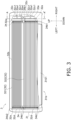
- Fig. 3 is a front view of the utilization unit 3.
- Fig. 4 is a cross-sectional view of the utilization unit 3 taken along line A-A' in Fig. 3.
- Fig. 3 illustrates the inside of the second casing 31 through a portion of the second casing 31 for convenience.
- Fig. 4 illustrates protrusion portions 34b (described later) of the first member 34 in a transparent manner for convenience.
- the second casing 31 is a housing having a substantially rectangular parallelepiped shape elongated in a left-right direction.
- the second casing 31 accommodates the utilization heat exchangers 32, the utilization fan 33, the first members 34, and the second members 35 therein.
- the second casing 31 has an inlet 31a, an outlet 31b, and openings 31c.
- the second casing 31 is an example of a casing.
- the inlet 31a is an opening through which indoor air flows into the second casing 31.
- the inlet 3 1a is formed in an upper portion of a front surface of the second casing 31.
- the outlet 3 1b is an opening through which the air heat-exchanged with the refrigerant in the utilization heat exchangers 32 is blown out.
- the outlet 31b is formed in a lower portion of the front surface of the second casing 31.
- the outlet 3 1b is closed by a flap 3 1b 1.
- the control unit 9 controls the posture (rotational angle) of the flap 3 1b1.
- the control unit 9 adjusts the opening degree of the outlet 3 1b by controlling the posture of the flap 31b1.
- the opening 31c is an opening for engaging a first fixing portion 35c (described later) of the second member 35.
- the second member 35 is provided in the vicinity of each end of the utilization heat exchangers 32 in the left-right direction. Furthermore, each second member 35 includes two first fixing portions 35c. Therefore, two openings 31c are also formed in the vicinity of each end of the utilization heat exchangers 32 in the left-right direction.
- the utilization fan 33 generates an air flow.
- the utilization fan 33 makes the indoor air pass through the utilization heat exchangers 32 by generating the air flow.
- the indoor air passing through the utilization heat exchangers 32 facilitates the heat exchange between the refrigerant in the utilization heat exchangers 32 and the outdoor air.
- the utilization fan 33 is a cross-flow fan in which a rotation shaft is disposed in the left-right direction.
- the utilization fan 33 is rotationally driven by a utilization fan motor 33a.
- the control unit 9 controls the air volume of the utilization fan 33 by changing the rotation speed of the utilization fan motor 33a.
- the utilization heat exchanger 32 exchanges heat between the refrigerant and the indoor air in the refrigerant circuit 100.
- One end of the utilization heat exchanger 32 is connected to the liquid-refrigerant connection pipe 5.
- the other end of the utilization heat exchanger 32 is connected to the gas-refrigerant connection pipe 6.
- the utilization heat exchanger 32 is an example of a heat exchanger.
- the utilization heat exchanger 32 is constituted of three utilization heat exchange sections including a first utilization heat exchange section 321, a second utilization heat exchange section 322, and a third utilization heat exchange section 323.
- the difference between the first utilization heat exchange section 321, the second utilization heat exchange section 322, and the third utilization heat exchange section 323 is the arrangement inside the second casing 31.
- the first utilization heat exchange section 321, the second utilization heat exchange section 322, and the third utilization heat exchange section 323 have an identical structure. Therefore, in the following description, the structure of the first utilization heat exchange section 321 will be described as an example, and descriptions of the structures of the second utilization heat exchange section 322 and the third utilization heat exchange section 323 will be omitted. Note that the arrangement of the first utilization heat exchange section 321, the second utilization heat exchange section 322, and the third utilization heat exchange section 323 inside the second casing 31 will be described later.
- the first utilization heat exchange section 321, the second utilization heat exchange section 322, and the third utilization heat exchange section 323 are collectively referred to, the first utilization heat exchange section 321, the second utilization heat exchange section 322, and the third utilization heat exchange section 323 are referred to as utilization heat exchange sections 321, 322, and 323.
- the utilization heat exchange sections 321, 322, and 323 are examples of a first heat exchange section.
- the first utilization heat exchange section 321 and the third utilization heat exchange section 323 are examples of a second heat exchange section.
- Fig. 5 is a perspective view of the first utilization heat exchange section 321.
- Fig. 6 is an enlarged cross-sectional view of the first utilization heat exchange section 321 taken along plane B in Fig. 5 .
- Fig. 7 is a view of the first utilization heat exchange section 321 as viewed in a thickness direction of a flat tube 32a.
- Fig. 7 also illustrates portions of the first members 34 for convenience. Respective directions such as the thickness direction, a width direction, and a longitudinal direction of the flat tube 32a used in the following description follow the directions indicated by arrows in Figs. 5 , 6 , and 7 .
- the first utilization heat exchange section 321 includes a plurality of flat tubes 32a, a plurality of heat transfer fins 32b, a first header 32c, a second header 32d, and a third header 32e.
- the first utilization heat exchange section 321 is a stacked heat exchanger in which the plurality of flat tubes 32a are stacked at predetermined intervals in the thickness direction of the flat tube 32a by the plurality of heat transfer fins 32b.
- the utilization heat exchanger 32 includes an inner utilization heat exchange section 32i and an outer utilization heat exchange section 32o.
- the flat tube 32a is a heat transfer tube in which a refrigerant flows.
- the flat tube 32a is formed in a flat oval shape in cross section.
- the flat tube 32a is a multi-hole tube having a plurality of refrigerant flow paths 32a1 formed so as to be orthogonal to the cross section.
- the plurality of refrigerant flow paths 32a1 are formed so as to be arranged in the width direction of the flat tube 32a.
- the flat tube 32a is formed by extrusion molding using, for example, aluminum or an aluminum alloy. In the present embodiment, the flat tube 32a is arranged such that the longitudinal direction of the flat tube 32a is in the left-right direction.
- the heat transfer fin 32b is a band-shaped plate member that supports the plurality of flat tubes 32a at predetermined intervals.
- the heat transfer fin 32b has a plurality of slit-shaped cutouts 32b1 for inserting the flat tubes 32a.
- the cutout 32b1 is formed so as to extend, as viewed in a thickness direction of the heat transfer fin 32b, from one end edge extending in a longitudinal direction of the heat transfer fin 32b toward the other end edge while being orthogonal to the one end edge.
- the plurality of cutouts 32b1 are formed at predetermined intervals in the longitudinal direction of the heat transfer fin 32b.
- the heat transfer fin 32b is formed by using, for example, aluminum or an aluminum alloy.
- the flat tube 32a is inserted into the cutout 32b 1 with the width direction of the flat tube 32a being in an extending direction of the cutout 32b 1 of the heat transfer fin 32b.
- the plurality of heat transfer fins 32b are arranged at predetermined intervals in the longitudinal direction of the flat tube 32a.
- the heat transfer fins 32b and the flat tubes 32a are joined by brazing at the cutouts 32b1.
- the plurality of flat tubes 32a are joined to the heat transfer fins 32b such that the end portions of the flat tubes 32a are arranged in the thickness direction of the flat tube 32a.
- Figs. 5 and 7 illustrate an outer edge formed by the plurality of heat transfer fins 32b arranged in the longitudinal direction of the flat tube 32a and portions of the plurality of heat transfer fins 32b for convenience.
- the inner utilization heat exchange section 32i and the outer utilization heat exchange section 32o are each formed by joining a predetermined number of flat tubes 32a to a predetermined number of heat transfer fins 32b and formed in a substantially identical shape.
- the inner utilization heat exchange section 32i and the outer utilization heat exchange section 32o are each arranged so as to overlap in the thickness direction of the flat tube 32a. With such an arrangement, as indicated by arrows in Fig. 6 , a gap formed between each adjacent flat tubes 32a of the inner utilization heat exchange section 32i and the outer utilization heat exchange section 32o and a gap formed between each adjacent heat transfer fins 32b of the inner utilization heat exchange section 32i and the outer utilization heat exchange section 32o form flow paths through which an air flow generated by the utilization fan 33 flows.
- the inner utilization heat exchange section 32i is disposed at a position closer to the utilization fan 33 than the outer utilization heat exchange section 32o.
- the first header 32c, the second header 32d, and the third header 32e are tubular members that allow the refrigerant flow paths 32a1 of the plurality of flat tubes 32a to communicate with each other at end portions of the plurality of flat tubes 32a.
- the first header 32c is provided at one end of each flat tubes 32a included in the inner utilization heat exchange section 32i in the longitudinal direction so as to allow the refrigerant flow paths 32a1 of the plurality of flat tubes 32a to communicate with each other. Specifically, each one end of the plurality of flat tubes 32a included in the inner utilization heat exchange section 32i in the longitudinal direction is inserted into the first header 32c through openings formed in a side surface of the first header 32c, and is fixed to the first header 32c using brazing or the like.
- the first header 32c is fixed to the flat tubes 32a so as to form, between the first header 32c and the heat transfer fin 32b of the inner utilization heat exchange section 32i adjacent to the first header 32c, a gap G1 of a predetermined width into which the protrusion portion 34b (described later) of the first member 34 can be inserted.
- the first header 32c is connected to the liquid-refrigerant connection pipe 5 via branch pipes 32c1.
- the second header 32d is provided at the other ends of the flat tubes 32a included in the inner utilization heat exchange section 32i in the longitudinal direction and the other ends of the flat tubes 32a included in the outer utilization heat exchange section 32o in the longitudinal direction so as to allow the refrigerant flow paths 32a1 of the plurality of flat tubes 32a of the inner utilization heat exchange section 32i and the refrigerant flow paths 32a1 of the plurality of flat tubes 32a of the outer utilization heat exchange section 32o to communicate with each other.
- the other ends of the flat tubes 32a included in the inner utilization heat exchange section 32i in the longitudinal direction and the other ends of the flat tubes 32a included in the outer utilization heat exchange section 32o in the longitudinal direction are inserted into the second header 32d through openings formed in a side surface of the second header 32d, and are fixed to the second header 32d using brazing or the like.
- the second header 32d is fixed to the flat tubes 32a so as to form, between the second header 32d and the heat transfer fin 32b of the inner utilization heat exchange section 32i adjacent to the second header 32d, a gap G2 of a predetermined width into which the protrusion portion 34b (described later) of the first member 34 can be inserted.
- the third header 32e is provided at one end of each flat tubes 32a included in the outer utilization heat exchange section 32o in the longitudinal direction so as to allow the refrigerant flow paths 32a1 of the plurality of flat tubes 32a to communicate with each other. Specifically, each one end of the plurality of flat tubes 32a included in the outer utilization heat exchange section 32o in the longitudinal direction is inserted into the third header 32e through openings formed in a side surface of the third header 32e, and is fixed to the third header 32e using brazing or the like. The third header 32e is connected to the gas-refrigerant connection pipe 6 via branch pipes 32e1.
- the refrigerant that has passed through the liquid-refrigerant connection pipe 5 and flowed into the first header 32c passes through the plurality of refrigerant flow paths 32a1 formed in the flat tubes 32a of the inner utilization heat exchange section 32i and flows into the second header 32d.
- the refrigerant that has flowed into the second header 32d passes through the plurality of refrigerant flow paths 32a1 formed in the outer utilization heat exchange section 32o, passes through the third header 32e, and flows into the gas-refrigerant connection pipe 6.
- the refrigerant that has passed through the gas-refrigerant connection pipe 6 and flowed into the third header 32e passes through the plurality of refrigerant flow paths 32a1 formed in the flat tubes 32a of the outer utilization heat exchange section 32o and flows into the second header 32d.
- the refrigerant that has flowed into the second header 32d passes through the plurality of refrigerant flow paths 32a1 formed in the inner utilization heat exchange section 32i, passes through the first header 32c, and flows into the liquid-refrigerant connection pipe 5.
- first header 32c, the second header 32d, and the third header 32e are collectively referred to, the first header 32c, the second header 32d, and the third header 32e are referred to as headers 32c, 32d, and 32e.
- the first utilization heat exchange section 321 is, when the utilization unit 3 is viewed in the left-right direction, provided such that the thickness direction of the flat tube 32a is inclined rearward with respect to the up-down direction (vertical direction) in front of the utilization fan 33.
- the second utilization heat exchange section 322 is, when the utilization unit 3 is viewed in the left-right direction, provided such that the thickness direction of the flat tube 32a is inclined frontward with respect to the up-down direction below the first utilization heat exchange section 321.
- the third utilization heat exchange section 323 is, when the utilization unit 3 is viewed in the left-right direction, provided such that the thickness direction of the flat tube 32a is inclined frontward with respect to the up-down direction behind and above the utilization fan 33.
- the first member 34 is attached to the utilization heat exchanger 32 and restricts the movement of the utilization heat exchanger 32 caused by vibration or the like accompanying the operation of the utilization unit 3 while supporting the utilization heat exchanger 32.
- the first member 34 is a plate-shaped member, and is disposed so as to be orthogonal to the left-right direction at each of left and right ends of the flat tubes 32a of the utilization heat exchanger 32 in a region surrounded by an outer periphery of the utilization fan 33 and the utilization heat exchanger 32.
- the first member 34 includes a body 34a and the protrusion portions 34b.
- the first member 34 is manufactured using a hard resin.
- a state where the first member 34 is attached to the utilization heat exchanger 32 means a state where the protrusion portions 34b are inserted between flat tubes 32a adjacent to each other in the thickness direction.
- the utilization unit 3 includes two first members 34.
- Each of the two first members 34 is disposed such that the body 34a faces the gap G1 or the gap G2 of the utilization heat exchanger 32.
- the first member 34 is attached to the utilization heat exchanger 32 vertically below the first utilization heat exchange section 321 and the third utilization heat exchange section 323 of the utilization heat exchanger 32 and behind the second utilization heat exchange section 322 of the utilization heat exchanger 32.
- Fig. 8 is a perspective view of the first member 34.
- the body 34a is a member having a polygonal shape in a plan view, mainly has a first cross-sectional surface 34a1, a second cross-sectional surface 34a2, a third cross-sectional surface 34a3, and a fourth cross-sectional surface 34a4, and has an opening 34a5 formed in a main surface.
- the first cross-sectional surface 34a1 is a surface that is formed so as to come in contact with at least an end portion of the heat transfer fin 32b included in the inner utilization heat exchange section 32i of the first utilization heat exchange section 321 and face the gap G1 or the gap G2 of the flat tubes 32a in a state where the first member 34 is attached to the utilization heat exchanger 32.
- the second cross-sectional surface 34a2 is a surface that is formed so as to come in contact with at least an end portion of the heat transfer fin 32b included in the inner utilization heat exchange section 32i of the second utilization heat exchange section 322 and face the gap G1 or the gap G2 of the flat tubes 32a in a state where the first member 34 is attached to the utilization heat exchanger 32.
- the third cross-sectional surface 34a3 is a surface that is formed so as to come in contact with at least an end portion of the heat transfer fin 32b included in the inner utilization heat exchange section 32i of the third utilization heat exchange section 323 and face the gap G1 or the gap G2 of the flat tubes 32a in a state where the first member 34 is attached to the utilization heat exchanger 32.
- the fourth cross-sectional surface 34a4 is a surface that is formed so as to position outside each end of the utilization fan 33 in the left-right direction.
- the fourth cross-sectional surface 34a4 is formed so as to come in contact with a body 35a (described later) of the second member 35.
- the opening 34a5 is an opening for engaging a second fixing portion 35d (described later) of the second member 35.
- the protrusion portions 34b are, in a state where each of the first cross-sectional surface 34a1, the second cross-sectional surface 34a2, and the third cross-sectional surface 34a3 is in contact with the flat tubes 32a of the inner utilization heat exchange section 32i, inserted between adjacent flat tubes 32a in the gap G1 or the gap G2.
- the protrusion portion 34b is a columnar protrusion.
- the protrusion portions 34b include first protrusion portions 34b 1, second protrusion portions 34b2, and third protrusion portions 34b3.
- the first protrusion portion 34b1 is inserted between adjacent flat tubes 32a in the gap G1 or the gap G2 of the inner utilization heat exchange section 32i that comes in contact with the first cross-sectional surface 34a1.
- the first protrusion portion 34b1 is formed so as to protrude from the first cross-sectional surface 34a1.
- the second protrusion portion 34b2 is inserted between adjacent flat tubes 32a in the gap G1 or the gap G2 of the inner utilization heat exchange section 32i that comes in contact with the second cross-sectional surface 34a2.
- the second protrusion portion 34b2 is formed so as to protrude from the second cross-sectional surface 34a2.
- the third protrusion portion 34b3 is inserted between adjacent flat tubes 32a in the gap G1 or the gap G2 of the inner utilization heat exchange section 32i that comes in contact with the third cross-sectional surface 34a3.
- the third protrusion portion 34b3 is formed so as to protrude from the third cross-sectional surface 34a3.
- the first member 34 provided on the left side of the utilization heat exchanger 32 includes three first protrusion portions 34b1, three second protrusion portions 34b2, and three third protrusion portions 34b3. Furthermore, the first member 34 provided on the right side of the utilization heat exchanger 32 includes two first protrusion portions 34b1, two second protrusion portions 34b2, and two third protrusion portions 34b3. The number of first protrusion portions 34b1, second protrusion portions 34b2, and third protrusion portions 34b3 is not limited to two or three, and may be one, four, or more.
- first protrusion portions 34b1, second protrusion portions 34b2, and third protrusion portions 34b3 included in the first member 34 provided on the left side of the utilization heat exchanger 32 may or may not be equal to the number of first protrusion portions 34b1, second protrusion portions 34b2, and third protrusion portions 34b3 included in the first member 34 provided on the right side of the utilization heat exchanger 32.
- the first member 34 restricts the movement of the utilization heat exchanger 32 in the thickness direction or the longitudinal direction of the flat tube 32a.
- the body 34a (specifically, the first cross-sectional surface 34a1, the second cross-sectional surface 34a2, and the third cross-sectional surface 34a3) comes in contact with the end portions of the heat transfer fins 32b included in the inner utilization heat exchange section 32i in a state where the first member 34 is attached to the utilization heat exchanger 32. In this manner, the first member 34 supports the utilization heat exchanger 32.
- the second member 35 is fixed to both the second casing 31 and the first member 34, and supports the utilization heat exchanger 32 via the first member 34.
- the second member 35 includes the body 35a, an insertion portion 35b, two first fixing portions 35c, and the second fixing portion 35d.
- the utilization unit 3 includes two second members 35. Each of the two second members 35 is disposed so as to support the first member 34 disposed on the right side of the utilization heat exchanger 32 or the first member 34 disposed on the left side of the utilization heat exchanger 32.
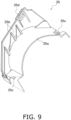
- Fig. 9 is a perspective view of the second member 35.
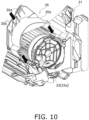
- Fig. 10 is an exploded perspective view illustrating how the first member 34 and the second member 35 are assembled to the second casing 31.
- the body 35a is an arc-shaped plate-shaped member that partially covers the upper side of the utilization fan 33 as viewed in the left-right direction.
- the body 35a is formed so as to come in contact with the fourth cross-sectional surface 34a4 of the first member 34.
- the insertion portion 35b restricts the movement of the first member 34 in the left-right direction.
- the insertion portion 35b is constituted of plate-shaped members that protrude from the body 35a so as to be orthogonal to the left-right direction.
- the plate-shaped members constituting the insertion portion 35b are provided with a gap of a predetermined width in the left-right direction so as to sandwich the body 34a of the first member 34 from the left-right direction.
- the body 34a of the first member 34 is inserted into the gap formed by the insertion portion 35b.
- the first fixing portions 35c fix the second member 35 to the second casing 31.
- the first fixing portions 35c are pawls that engage with the openings 31c of the second casing 31.
- the first fixing portions 35c are formed so as to protrude downward from end portions of the body 35a in the circumferential direction as viewed in the left-right direction. As illustrated in Figs. 10 and 4 , by covering the upper side of the utilization fan 33 with the body 35a, the first fixing portions 35c engage with the openings 31c. The movement of the second member 35 in the up-down direction is restricted by the engagement of the first fixing portions 35c with the openings 31c, and the second member 35 is fixed to the second casing 31.
- the second fixing portion 35d fixes the first member 34 to the second member 35.
- the second fixing portion 35d is a pawl that engages with the opening 34a5 of the first member 34. As illustrated in Fig. 10 , by inserting the first member 34 into the insertion portion 35b, the second fixing portion 35d engages with the opening 34a5. The first member 34 is fixed to the second member 35 by the engagement of the second fixing portion 35d with the opening 34a5, thereby restricting the movement of the first member 34 in the up-down direction.
- the first member 34 is fixed to the second member 35, and the second member 35 is fixed to the second casing 31. Therefore, the second member 35 can support the utilization heat exchanger 32 via the first member 34.
- the second member 35 also has a function of allowing the condensed water generated in the utilization heat exchanger 32 to flow to a drain pan (not illustrated) provided below the second member 35 at each of the front and rear of the utilization fan 33. Specifically, when the condensed water generated in the utilization heat exchanger 32 falls from an end portion of the utilization heat exchanger 32 to the body 35a, the condensed water moves along an upper surface of the body 35a to a front end portion or a rear end portion and falls to the drain pan.
- the remote controller 8 receives, from a user, an instruction to execute a heating operation, a cooling operation, a humidifying operation, or the like, an instruction to stop the air-conditioning apparatus 1, and a set value such as a set temperature Ts, and transmits the received result to the control unit 9 as a control signal.
- the control unit 9 is mainly connected to the compressor 22, the four-way switching valve 23, the heat source expansion valve 25, the heat source fan 26, the utilization fan 33, and the remote controller 8 so as to be capable of transmitting and receiving a control signal. Although details will be described later, the control unit 9 controls the refrigerant circuit 100 by controlling an operation of each of the compressor 22, the four-way switching valve 23, the heat source expansion valve 25, the heat source fan 26, and the utilization fan 33.
- the control unit 9 is typically realized by a computer including a control arithmetic device and a storage device (both not illustrated).
- the control arithmetic device is a processor such as a CPU or a GPU.
- the control arithmetic device reads a control program stored in the storage device and controls an operation in accordance with the control program.
- the control arithmetic device can write a calculation result in the storage device and read information stored in the storage device in accordance with the control program.
- Fig. 2 is a schematic view.
- the control unit 9 is constituted of an outdoor control unit provided inside the heat source unit 2 and an indoor control unit provided inside the utilization unit 3.
- the outdoor control unit and the indoor control unit may be connected by a communication line capable of transmitting and receiving a control signal to and from each other.
- the control unit 9 starts a heating operation when receiving a control signal regarding an instruction to execute the heating operation from the remote controller 8.
- the control unit 9 switches the four-way switching valve 23 to the first state (see the broken lines in Fig. 2 ).
- the control unit 9 sets the opening degree of the heat source expansion valve 25 to the degree corresponding to the set temperature Ts received from the remote controller 8, operates the compressor 22, and rotationally drives the utilization fan 33.
- the heat source heat exchanger 24 functions as an evaporator of the refrigerant
- the utilization heat exchanger 32 functions as a condenser of the refrigerant.
- the refrigerant circuit 100 functions as follows.
- a highpressure refrigerant discharged from the compressor 22 exchanges heat with indoor air sent by the utilization fan 33 and is condensed in the utilization heat exchanger 32.
- the indoor air is heated and discharged into the room as conditioned air.
- the condensed refrigerant passes through the heat source expansion valve 25 and is decompressed, and thereafter, exchanges heat with outdoor air sent by the heat source fan 26 and is evaporated in the heat source heat exchanger 24.
- the refrigerant that has passed through the heat source heat exchanger 24 is sucked into the compressor 22 and is compressed.
- the control unit 9 starts a cooling operation when receiving a control signal regarding an instruction to execute the cooling operation from the remote controller 8.
- the control unit 9 switches the four-way switching valve 23 to the second state (see the solid lines in Fig. 2 ).
- the control unit 9 sets the opening degree of the heat source expansion valve 25 to the degree corresponding to the set temperature Ts received from the remote controller 8, operates the compressor 22, and rotationally drives the utilization fan 33.
- the heat source heat exchanger 24 functions as a condenser of the refrigerant
- the utilization heat exchanger 32 functions as an evaporator of the refrigerant.
- the refrigerant circuit 100 functions as follows.
- a highpressure refrigerant discharged from the compressor 22 exchanges heat with outdoor air sent by the heat source fan 26 and is condensed in the heat source heat exchanger 24.
- the condensed refrigerant passes through the heat source expansion valve 25 and is decompressed, and thereafter, exchanges heat with indoor air sent by the utilization fan 33 and is evaporated in the utilization heat exchanger 32.
- the indoor air is cooled and discharged into the room as conditioned air.
- the refrigerant that has passed through the utilization heat exchanger 32 is sucked into the compressor 22 and is compressed.
- the utilization unit 3 includes the utilization heat exchanger 32, the first member 34, and the second member 35.
- the utilization heat exchanger 32 a plurality of flat tubes 32a are stacked at predetermined intervals in the thickness direction by the heat transfer fins 32b.
- the first member 34 is attached to the utilization heat exchanger 32.
- the second member 35 supports the utilization heat exchanger 32 via the first member 34.
- the first member 34 includes the body 34a and the protrusion portion 34b protruding from the body 34a.
- the protrusion portion 34b is inserted between adjacent flat tubes 32a.
- the protrusion portion 34b included in the first member 34 is inserted between adjacent flat tubes 32a, thereby restricting the movement of the utilization heat exchanger 32 in the thickness direction or the longitudinal direction of the flat tube 32a.
- the contact area between the flat tube 32a and the member (first member 34) that comes in contact with the flat tube 32a to restrict the movement can be significantly reduced as compared with the case where the heat transfer tube is inserted into the tube hole formed in the bracket to restrict the movement of the heat exchanger. Therefore, even if the first member 34 and the flat tube 32a slide against each other due to vibration or the like caused by the operation of the utilization unit 3, damage to the flat tube 32a caused by this sliding is prevented. As a result, options for materials that can be used for the flat tube 32a increase, thereby reducing the manufacturing cost of the utilization unit 3.
- the first member 34 includes the plurality of protrusion portions 34b.
- the utilization unit 3 including the utilization heat exchanger 32 having a plurality of heat exchange sections (the first utilization heat exchange section 321, the second utilization heat exchange section 322, and the third utilization heat exchange section 323), the first member 34 includes the plurality of protrusion portions 34b for each of the utilization heat exchange sections 321, 322, and 323.
- the first member 34 including the plurality of protrusion portions 34b effectively restricts the movement of the utilization heat exchanger 32 in the thickness direction or the longitudinal direction of the flat tube 32a.
- the protrusion portion 34b has a columnar shape.
- the protrusion portion 34b formed in a columnar shape enables easy insertion of the protrusion portion 34b between adjacent flat tubes 32a. Therefore, the manufacturing of the utilization unit 3 is facilitated, thereby reducing the manufacturing cost of the utilization unit 3.
- the first member 34 is manufactured using resin.
- the hardness of the protrusion portion 34b can be reduced as compared with a case where the first member 34 is manufactured using metal. Therefore, even if the first member 34 and the flat tube 32a slide against each other, damage to the flat tube 32a caused by this sliding is prevented. As a result, options for materials that can be used for the flat tube 32a increase, thereby reducing the manufacturing cost of the utilization unit 3.
- the utilization unit 3 further includes the second casing 31 and the second member 35 fixed to the second casing 31.
- the first member 34 is fixed to the second member 35 by engagement.
- the body 34a of the first member 34 is in contact with the heat transfer fin 32b.
- the first member 34 is formed such that the first cross-sectional surface 34a1, the second cross-sectional surface 34a2, and the third cross-sectional surface 34a3 of the body 34a are in contact with the end portions of the heat transfer fins 32b included in the inner utilization heat exchange section 32i in a state where the first member 34 is attached to the utilization heat exchanger 32. Therefore, the first member 34 can receive the weight of the utilization heat exchanger 32 by the contact between the first cross-sectional surface 34a1, the second cross-sectional surface 34a2, and the third cross-sectional surface 34a3 of the body 34a and the heat transfer fins 32b included in the inner utilization heat exchange section 32i.
- the weight of the utilization heat exchanger 32 received by the protrusion portions 34b becomes substantially zero or is significantly reduced. Therefore, even if the first member 34 and the flat tube 32a slide against each other, damage to the flat tube 32a caused by this sliding is prevented. As a result, options for the flat tube 32a that can be used increase, thereby reducing the manufacturing cost of the utilization unit 3.
- the utilization heat exchanger 32 includes, as viewed in the left-right direction, the first utilization heat exchange section 321 and the third utilization heat exchange section 323 in which the thickness direction of the flat tube 32a is inclined with respect to the vertical direction.
- the first member 34 is attached to the utilization heat exchanger 32 vertically below the first utilization heat exchange section 321 and the third utilization heat exchange section 323.
- the first member 34 can restrict the movement of the first utilization heat exchange section 321 and the third utilization heat exchange section 323 while supporting the first utilization heat exchange section 321 and the third utilization heat exchange section 323.
- the protrusion portion 34b may include a pawl portion 34c that engages with the flat tubes 32a.
- the pawl portion 34c is formed so as to engage with the end portions, on the outer utilization heat exchange section 32o side, of the flat tubes 32a of the inner utilization heat exchange section 32i by inserting the protrusion portion 34b between adjacent flat tubes 32a.
- Fig. 11 is an enlarged cross-sectional view of a periphery of the utilization heat exchanger 32 of the air-conditioning apparatus 1 according to a modification A.
- the first member 34 can effectively restrict the movement of the utilization heat exchanger 32 by the engagement of the pawl portion 34c with the end portions of the flat tubes 32a.
- the first member 34 may be manufactured using a material other than resin.
- the first member 34 may be manufactured using metal, and a resin coating may be applied to a surface of the first member 34.
- the first member 34 may be manufactured using metal, and an insulating rubber may be attached to the surface of the first member 34.
- the resin coating or the insulating rubber reduces the hardness of the surface of the first member 34 to a low level. As a result, it is possible to ensure high rigidity of the first member 34 while effectively preventing damage to the flat tube 32a caused by sliding.
- the first member 34 is fixed to the second member 35 by the engagement of the second fixing portion 35d with the opening 34a5 of the first member 34.
- the fixing method is not limited thereto.
- the first member 34 may be fixed to the second member 35 by screw fastening.
- the body 34a of the first member 34 may be in contact with any one of the headers 32c, 32d, and 32e.
- the body 34a of the first member 34 is in contact with any one of the headers 32c, 32d, and 32e, so that the first member 34 can receive the weight of the utilization heat exchanger 32 by the contact between the body 34a and any one of the headers 32c, 32d, and 32e.
- the weight of the utilization heat exchanger 32 received by the protrusion portions 34b becomes substantially zero or is significantly reduced. Therefore, even if the first member 34 and the flat tube 32a slide against each other, damage to the flat tube 32a caused by this sliding is prevented. As a result, options for the flat tube 32a that can be used increase, thereby reducing the manufacturing cost of the utilization unit 3.
- the utilization heat exchanger 32 includes a plurality of utilization heat exchange sections 321, 322, and 323, but the utilization heat exchanger 32 may be constituted of only one heat exchange section.
- the second casing 31 may be the second member.
- the second casing 31 may function as the second member to support the first member 34.
- the utilization unit 3 including the first member 34 has been described above as an embodiment, but the heat source unit 2 may include the first member attached to the heat source heat exchanger 24.
Landscapes
- Engineering & Computer Science (AREA)
- Physics & Mathematics (AREA)
- Mechanical Engineering (AREA)
- General Engineering & Computer Science (AREA)
- Thermal Sciences (AREA)
- Chemical & Material Sciences (AREA)
- Combustion & Propulsion (AREA)
- Geometry (AREA)
- Heat-Exchange Devices With Radiators And Conduit Assemblies (AREA)
- Air Filters, Heat-Exchange Apparatuses, And Housings Of Air-Conditioning Units (AREA)
Abstract
Description
- The present disclosure relates to a heat exchange unit.
- There is known a heat exchange unit including a heat exchanger having a plurality of heat transfer tubes arranged substantially in parallel at predetermined intervals in a vertical direction and a plurality of heat transfer fins joined to the heat transfer tubes.
- PTL 1 (International Publication No.
2018/128035 ) discloses a heat exchange unit (outdoor heat exchanger) including a heat exchanger in which thin and flattened flat tubes are used as heat transfer tubes and brackets that are members that restrict the movement of the heat exchanger while supporting the heat exchanger. In the heat exchange unit according toPTL 1, the bracket is a plate-shaped member in which tube holes into which the heat transfer tubes are inserted are formed. The heat transfer tube inserted into the tube hole is fixed to a housing by being joined to the bracket by brazing. - In some cases, corrosion caused by aging may prevent the bracket and the heat transfer tube from being joined to each other in a portion joined using brazing. In such a case, the heat transfer tube slides against the tube hole formed in the bracket due to vibration or the like accompanying the operation of the heat exchange unit. In a case where a flat tube formed to have a relatively thin wall thickness is used as a heat transfer tube, as in the heat exchange unit according to
PTL 1, there is a risk of the flat tube being damaged from a portion sliding against the tube hole. Therefore, there is a problem that options for materials that can be used for the flat tube are limited and a manufacturing cost is likely to increase. - The present disclosure proposes a heat exchange unit capable of suppressing an increase in manufacturing cost by preventing damage to a flat tube caused by sliding against other members.
- A heat exchange unit according to a first aspect includes a heat exchanger and a first member. In the heat exchanger, a plurality of flat tubes are stacked at predetermined intervals in a thickness direction by a heat transfer fin. The first member is attached to the heat exchanger. The first member includes a body and a protrusion portion protruding from the body, and the protrusion portion is inserted between flat tubes adjacent to each other.
- According to the heat exchange unit, the contact area between the flat tube and the member (first member) that comes in contact with the flat tube to restrict the movement can be significantly reduced as compared with the case where the heat transfer tube is inserted into the tube hole formed in the bracket to restrict the movement of the heat exchanger. Therefore, even if the first member and the flat tube slide against each other due to vibration or the like caused by the operation of the utilization unit, damage to the flat tube caused by this sliding is prevented. As a result, options for materials that can be used for the flat tube increase, thereby reducing the manufacturing cost of the heat exchange unit.
- A heat exchange unit according to a second aspect is the heat exchange unit according to the first aspect, in which the first member includes a plurality of protrusion portions.
- According to the heat exchange unit, the first member including the plurality of protrusion portions effectively restricts the movement of the heat exchanger.
- A heat exchange unit according to a third aspect is the heat exchange unit according to the first or second aspect, in which the heat exchanger includes a plurality of first heat exchange sections. The first member includes a plurality of protrusion portions for each of the plurality of first heat exchange sections.
- According to the heat exchange unit, the first member including the plurality of protrusion portions effectively restricts the movement of the heat exchanger.
- A heat exchange unit according to a fourth aspect is the heat exchange unit according to any one of the first to third aspects, in which the protrusion portion has a columnar shape.
- According to the heat exchange unit, the protrusion portion can be easily inserted between flat tubes adjacent to each other. Therefore, the manufacturing of the heat exchange unit is facilitated, thereby reducing the manufacturing cost of the heat exchange unit.
- A heat exchange unit according to a fifth aspect is the heat exchange unit according to any one of the first to third aspects, in which the protrusion portion includes a pawl portion that engages with a flat tube.
- According to the heat exchange unit, the first member can effectively restrict the movement of the heat exchanger.
- A heat exchange unit according to a sixth aspect is the heat exchange unit according to any one of the first to fifth aspects, in which the first member is manufactured using resin.
- According to the heat exchange unit, the hardness of the protrusion portion can be reduced as compared with a case where the first member is manufactured using metal. Therefore, even if the first member and the flat tube slide against each other, damage to the flat tube caused by this sliding is prevented. As a result, options for materials that can be used for the flat tube increase, thereby reducing the manufacturing cost of the heat exchange unit.
- A heat exchange unit according to a seventh aspect is the heat exchange unit according to any one of the first to fifth aspects, in which the first member is manufactured using metal, and a resin coating is applied to a surface of the first member.
- According to the heat exchange unit, the resin coating reduces the hardness of the surface of the first member to a low level. As a result, it is possible to ensure high rigidity of the first member while effectively preventing damage to the flat tube caused by sliding.
- A heat exchange unit according to an eighth aspect is the heat exchange unit according to any one of the first to fifth aspects, in which the first member is manufactured using metal, and an insulating rubber is attached to a surface of the first member.
- According to the heat exchange unit, the insulating rubber reduces the hardness of the surface of the first member to a low level. As a result, it is possible to ensure high rigidity of the first member while effectively preventing damage to the flat tube caused by sliding.
- A heat exchange unit according to a ninth aspect is the heat exchange unit according to any one of the first to eighth aspects, and further includes a casing and a second member fixed to the casing. The first member is fixed to the second member by screw fastening or engagement.
- A heat exchange unit according to a tenth aspect is the heat exchange unit according to any one of the first to ninth aspects, in which the body of the first member is in contact with the heat transfer fin.
- According to the heat exchange unit, the first member can receive the weight of the heat exchanger by the contact between the body and the heat transfer fin. Thus, the weight of the heat exchanger received by the protrusion portion becomes substantially zero or is significantly reduced. Therefore, even if the first member and the flat tube slide against each other, damage to the flat tube caused by this sliding is prevented. As a result, options for the flat tube that can be used increase, thereby reducing the manufacturing cost of the heat exchange unit.
- A heat exchange unit according to an eleventh aspect is the heat exchange unit according to any one of the first to ninth aspects, in which the heat exchanger further includes a header that connects end portions of the plurality of flat tubes to each other. The body of the first member is in contact with the header.
- According to the heat exchange unit, the first member can receive the weight of the heat exchanger through the body as well as the protrusion portion, thereby reducing the weight of the heat exchanger received by the protrusion portion. Therefore, even if the first member and the flat tube slide against each other, damage to the flat tube caused by this sliding is prevented. As a result, options for the flat tube that can be used increase, thereby reducing the manufacturing cost of the heat exchange unit.
- A heat exchange unit according to a twelfth aspect is the heat exchange unit according to any one of the first to eleventh aspects, in which the heat exchanger includes a second heat exchange section in which the thickness direction of the flat tubes is inclined with respect to a vertical direction. The first member is attached to the heat exchanger vertically below the second heat exchange section.
- According to the heat exchange unit, the first member can restrict the movement of the second heat exchange section while supporting the second heat exchange section.
-
-
Fig. 1 is a diagram illustrating an overall configuration of an air-conditioning apparatus 1. -
Fig. 2 is a conceptual diagram of the air-conditioning apparatus 1. -
Fig. 3 is a front view of autilization unit 3. -
Fig. 4 is a cross-sectional view of theutilization unit 3 taken along line A-A' inFig. 3 . -
Fig. 5 is a perspective view of a first utilizationheat exchange section 321. -
Fig. 6 is an enlarged cross-sectional view of the first utilizationheat exchange section 321 taken along plane B inFig. 5 . -
Fig. 7 is a view of the first utilizationheat exchange section 321 as viewed in a thickness direction of aflat tube 32a. -
Fig. 8 is a perspective view of afirst member 34. -
Fig. 9 is a perspective view of asecond member 35. -
Fig. 10 is an exploded perspective view illustrating how thefirst member 34 and thesecond member 35 are assembled to asecond casing 31. -
Fig. 11 is an enlarged cross-sectional view of a periphery of autilization heat exchanger 32 of the air-conditioning apparatus 1 according to a modification A. - The application of a heat exchange unit according to the present disclosure is not limited. For example, the heat exchange unit is used in a utilization unit of an air-conditioning apparatus that utilizes a vapor compression refrigeration cycle. In the following description, an air-
conditioning apparatus 1 in which autilization unit 3, which is an example of a heat exchange unit of the present disclosure, is used will be described with reference to the drawings. - The air-
conditioning apparatus 1 performs air conditioning of the inside of a room RM (indoors), which is a target space, by a vapor compression refrigeration cycle. The air-conditioning apparatus 1 mainly includes aheat source unit 2, theutilization unit 3, a liquid-refrigerant connection pipe 5, a gas-refrigerant connection pipe 6, aremote controller 8, and acontrol unit 9. - The liquid-
refrigerant connection pipe 5 and the gas-refrigerant connection pipe 6 connect theheat source unit 2 and theutilization unit 3 to each other. Theheat source unit 2, theutilization unit 3, the liquid-refrigerant connection pipe 5, and the gas-refrigerant connection pipe 6 are annularly connected by a refrigerant pipe, and form arefrigerant circuit 100. Therefrigerant circuit 100 is filled with a refrigerant. Although details will be described later, thecontrol unit 9 controls each device of the air-conditioning apparatus 1 to perform air conditioning operations such as a heating operation and a cooling operation. -
Fig. 1 is a diagram illustrating an overall configuration of the air-conditioning apparatus 1.Fig. 2 is a conceptual diagram of the air-conditioning apparatus 1. Respective directions such as up, down, front, rear, left, and right used in the following description follow the directions indicated by arrows inFigs. 1 ,3 , and4 . - The
heat source unit 2 is installed outside the room RM (outdoors, for example, on a roof of a building, near an outer wall surface of a building, or the like). Theheat source unit 2 mainly includes afirst casing 21, acompressor 22, a four-way switching valve 23, a heatsource heat exchanger 24, a heatsource expansion valve 25, aheat source fan 26, and ashutoff valve 27. - The
first casing 21 is a housing having a substantially rectangular parallelepiped shape. Thefirst casing 21 accommodates thecompressor 22, the four-way switching valve 23, the heatsource heat exchanger 24, the heatsource expansion valve 25, and theheat source fan 26 therein. - In the
refrigerant circuit 100, thecompressor 22 sucks a low-pressure refrigerant from asuction side 22a, compresses the refrigerant to a high pressure, and thereafter, discharges the refrigerant from adischarge side 22b. Thecompressor 22 includes a compression element (not illustrated) and a compressor motor (not illustrated) that rotationally drives the compression element. Thecontrol unit 9 controls the rotation speed of the compressor motor via an inverter or the like. Thecontrol unit 9 controls the capacity of thecompressor 22 by changing the rotation speed of the compressor motor. - The four-
way switching valve 23 switches a flow direction of the refrigerant in therefrigerant circuit 100. The four-way switching valve 23 includes a first port P1, a second port P2, a third port P3, and a fourth port P4. Thecontrol unit 9 switches the four-way switching valve 23 between a first state (a state indicated by broken lines inFig. 2 ) and a second state (a state indicated by solid lines inFig. 2 ). In the first state, the first port P1 and the fourth port P4 communicate with each other, and the second port P2 and the third port P3 communicate with each other. In the second state, the first port P1 and the second port P2 communicate with each other and the third port P3 and the fourth port P4 communicate with each other. - The first port P1 is connected to the
discharge side 22b of thecompressor 22. The second port P2 is connected to a gas side of the heatsource heat exchanger 24. The third port P3 is connected to thesuction side 22a of thecompressor 22. The fourth port P4 is connected to the gas-refrigerant connection pipe 6. - The heat
source heat exchanger 24 is a heat exchanger that exchanges heat between the refrigerant and outdoor air. One end of the heatsource heat exchanger 24 is connected to the heatsource expansion valve 25. The other end of the heatsource heat exchanger 24 is connected to the second port P2 of the four-way switching valve 23. - The heat
source expansion valve 25 is an expansion mechanism that decompresses the refrigerant in therefrigerant circuit 100. The heatsource expansion valve 25 is provided between the liquid-refrigerant connection pipe 5 and a liquid side of the heatsource heat exchanger 24. The heatsource expansion valve 25 is an electric expansion valve whose opening degree is controllable. Thecontrol unit 9 controls the opening degree of the heatsource expansion valve 25. - The
heat source fan 26 generates an air flow and sends the outdoor air to the heatsource heat exchanger 24. Theheat source fan 26 facilitates heat exchange between the refrigerant in the heatsource heat exchanger 24 and the outdoor air by sending the outdoor air to the heatsource heat exchanger 24. Theheat source fan 26 is rotationally driven by a heatsource fan motor 26a. Thecontrol unit 9 controls the air volume of theheat source fan 26 by changing the rotation speed of the heatsource fan motor 26a. - The
shutoff valve 27 is a valve that is manually opened or closed. For example, theshutoff valve 27 is opened or closed by an installation worker at the time of installation or the like of the air-conditioning apparatus 1. Theshutoff valve 27 includes a liquid-side shutoff valve 27a and a gas-side shutoff valve 27b. The liquid-side shutoff valve 27a is provided in therefrigerant circuit 100 between the heatsource expansion valve 25 and the liquid-refrigerant connection pipe 5. The gas-side shutoff valve 27b is provided in therefrigerant circuit 100 between the fourth port P4 of the four-way switching valve 23 and the gas-refrigerant connection pipe 6. - The
utilization unit 3 is a wall-hung type indoor air conditioner that is hung and mounted on a wall WL in the room RM. Theutilization unit 3 mainly includes asecond casing 31, threeutilization heat exchangers 32, autilization fan 33, twofirst members 34, and twosecond members 35. -
Fig. 3 is a front view of theutilization unit 3.Fig. 4 is a cross-sectional view of theutilization unit 3 taken along line A-A' inFig. 3. Fig. 3 illustrates the inside of thesecond casing 31 through a portion of thesecond casing 31 for convenience.Fig. 4 illustratesprotrusion portions 34b (described later) of thefirst member 34 in a transparent manner for convenience. - The
second casing 31 is a housing having a substantially rectangular parallelepiped shape elongated in a left-right direction. Thesecond casing 31 accommodates theutilization heat exchangers 32, theutilization fan 33, thefirst members 34, and thesecond members 35 therein. Thesecond casing 31 has aninlet 31a, anoutlet 31b, andopenings 31c. - The
second casing 31 is an example of a casing. - The
inlet 31a is an opening through which indoor air flows into thesecond casing 31. Theinlet 3 1a is formed in an upper portion of a front surface of thesecond casing 31. - The
outlet 3 1b is an opening through which the air heat-exchanged with the refrigerant in theutilization heat exchangers 32 is blown out. Theoutlet 31b is formed in a lower portion of the front surface of thesecond casing 31. Theoutlet 3 1b is closed by aflap 31b 1. Thecontrol unit 9 controls the posture (rotational angle) of theflap 3 1b1. Thecontrol unit 9 adjusts the opening degree of theoutlet 3 1b by controlling the posture of the flap 31b1. - The
opening 31c is an opening for engaging afirst fixing portion 35c (described later) of thesecond member 35. Although details will be described later, in the present embodiment, thesecond member 35 is provided in the vicinity of each end of theutilization heat exchangers 32 in the left-right direction. Furthermore, eachsecond member 35 includes twofirst fixing portions 35c. Therefore, twoopenings 31c are also formed in the vicinity of each end of theutilization heat exchangers 32 in the left-right direction. - The
utilization fan 33 generates an air flow. Theutilization fan 33 makes the indoor air pass through theutilization heat exchangers 32 by generating the air flow. The indoor air passing through theutilization heat exchangers 32 facilitates the heat exchange between the refrigerant in theutilization heat exchangers 32 and the outdoor air. Theutilization fan 33 is a cross-flow fan in which a rotation shaft is disposed in the left-right direction. - The
utilization fan 33 is rotationally driven by autilization fan motor 33a. Thecontrol unit 9 controls the air volume of theutilization fan 33 by changing the rotation speed of theutilization fan motor 33a. - The
utilization heat exchanger 32 exchanges heat between the refrigerant and the indoor air in therefrigerant circuit 100. One end of theutilization heat exchanger 32 is connected to the liquid-refrigerant connection pipe 5. The other end of theutilization heat exchanger 32 is connected to the gas-refrigerant connection pipe 6. - The
utilization heat exchanger 32 is an example of a heat exchanger. - In the present embodiment, the
utilization heat exchanger 32 is constituted of three utilization heat exchange sections including a first utilizationheat exchange section 321, a second utilizationheat exchange section 322, and a third utilizationheat exchange section 323. The difference between the first utilizationheat exchange section 321, the second utilizationheat exchange section 322, and the third utilizationheat exchange section 323 is the arrangement inside thesecond casing 31. The first utilizationheat exchange section 321, the second utilizationheat exchange section 322, and the third utilizationheat exchange section 323 have an identical structure. Therefore, in the following description, the structure of the first utilizationheat exchange section 321 will be described as an example, and descriptions of the structures of the second utilizationheat exchange section 322 and the third utilizationheat exchange section 323 will be omitted. Note that the arrangement of the first utilizationheat exchange section 321, the second utilizationheat exchange section 322, and the third utilizationheat exchange section 323 inside thesecond casing 31 will be described later. - Note that, in a case where the first utilization
heat exchange section 321, the second utilizationheat exchange section 322, and the third utilizationheat exchange section 323 are collectively referred to, the first utilizationheat exchange section 321, the second utilizationheat exchange section 322, and the third utilizationheat exchange section 323 are referred to as utilizationheat exchange sections - The utilization
heat exchange sections heat exchange section 321 and the third utilizationheat exchange section 323 are examples of a second heat exchange section. -
Fig. 5 is a perspective view of the first utilizationheat exchange section 321.Fig. 6 is an enlarged cross-sectional view of the first utilizationheat exchange section 321 taken along plane B inFig. 5 .Fig. 7 is a view of the first utilizationheat exchange section 321 as viewed in a thickness direction of aflat tube 32a.Fig. 7 also illustrates portions of thefirst members 34 for convenience. Respective directions such as the thickness direction, a width direction, and a longitudinal direction of theflat tube 32a used in the following description follow the directions indicated by arrows inFigs. 5 ,6 , and7 . - The first utilization
heat exchange section 321 includes a plurality offlat tubes 32a, a plurality ofheat transfer fins 32b, afirst header 32c, asecond header 32d, and athird header 32e. The first utilizationheat exchange section 321 is a stacked heat exchanger in which the plurality offlat tubes 32a are stacked at predetermined intervals in the thickness direction of theflat tube 32a by the plurality ofheat transfer fins 32b. In the present embodiment, theutilization heat exchanger 32 includes an inner utilizationheat exchange section 32i and an outer utilization heat exchange section 32o. - The
flat tube 32a is a heat transfer tube in which a refrigerant flows. Theflat tube 32a is formed in a flat oval shape in cross section. Theflat tube 32a is a multi-hole tube having a plurality of refrigerant flow paths 32a1 formed so as to be orthogonal to the cross section. The plurality of refrigerant flow paths 32a1 are formed so as to be arranged in the width direction of theflat tube 32a. Theflat tube 32a is formed by extrusion molding using, for example, aluminum or an aluminum alloy. In the present embodiment, theflat tube 32a is arranged such that the longitudinal direction of theflat tube 32a is in the left-right direction. - The
heat transfer fin 32b is a band-shaped plate member that supports the plurality offlat tubes 32a at predetermined intervals. Theheat transfer fin 32b has a plurality of slit-shaped cutouts 32b1 for inserting theflat tubes 32a. The cutout 32b1 is formed so as to extend, as viewed in a thickness direction of theheat transfer fin 32b, from one end edge extending in a longitudinal direction of theheat transfer fin 32b toward the other end edge while being orthogonal to the one end edge. The plurality of cutouts 32b1 are formed at predetermined intervals in the longitudinal direction of theheat transfer fin 32b. Theheat transfer fin 32b is formed by using, for example, aluminum or an aluminum alloy. - The
flat tube 32a is inserted into thecutout 32bflat tube 32a being in an extending direction of thecutout 32bheat transfer fin 32b. The plurality ofheat transfer fins 32b are arranged at predetermined intervals in the longitudinal direction of theflat tube 32a. Theheat transfer fins 32b and theflat tubes 32a are joined by brazing at the cutouts 32b1. The plurality offlat tubes 32a are joined to theheat transfer fins 32b such that the end portions of theflat tubes 32a are arranged in the thickness direction of theflat tube 32a.Figs. 5 and7 illustrate an outer edge formed by the plurality ofheat transfer fins 32b arranged in the longitudinal direction of theflat tube 32a and portions of the plurality ofheat transfer fins 32b for convenience. - The inner utilization
heat exchange section 32i and the outer utilization heat exchange section 32o are each formed by joining a predetermined number offlat tubes 32a to a predetermined number ofheat transfer fins 32b and formed in a substantially identical shape. The inner utilizationheat exchange section 32i and the outer utilization heat exchange section 32o are each arranged so as to overlap in the thickness direction of theflat tube 32a. With such an arrangement, as indicated by arrows inFig. 6 , a gap formed between each adjacentflat tubes 32a of the inner utilizationheat exchange section 32i and the outer utilization heat exchange section 32o and a gap formed between each adjacentheat transfer fins 32b of the inner utilizationheat exchange section 32i and the outer utilization heat exchange section 32o form flow paths through which an air flow generated by theutilization fan 33 flows. The inner utilizationheat exchange section 32i is disposed at a position closer to theutilization fan 33 than the outer utilization heat exchange section 32o. - The
first header 32c, thesecond header 32d, and thethird header 32e are tubular members that allow the refrigerant flow paths 32a1 of the plurality offlat tubes 32a to communicate with each other at end portions of the plurality offlat tubes 32a. - The
first header 32c is provided at one end of eachflat tubes 32a included in the inner utilizationheat exchange section 32i in the longitudinal direction so as to allow the refrigerant flow paths 32a1 of the plurality offlat tubes 32a to communicate with each other. Specifically, each one end of the plurality offlat tubes 32a included in the inner utilizationheat exchange section 32i in the longitudinal direction is inserted into thefirst header 32c through openings formed in a side surface of thefirst header 32c, and is fixed to thefirst header 32c using brazing or the like. - The
first header 32c is fixed to theflat tubes 32a so as to form, between thefirst header 32c and theheat transfer fin 32b of the inner utilizationheat exchange section 32i adjacent to thefirst header 32c, a gap G1 of a predetermined width into which theprotrusion portion 34b (described later) of thefirst member 34 can be inserted. Thefirst header 32c is connected to the liquid-refrigerant connection pipe 5 via branch pipes 32c1. - The
second header 32d is provided at the other ends of theflat tubes 32a included in the inner utilizationheat exchange section 32i in the longitudinal direction and the other ends of theflat tubes 32a included in the outer utilization heat exchange section 32o in the longitudinal direction so as to allow the refrigerant flow paths 32a1 of the plurality offlat tubes 32a of the inner utilizationheat exchange section 32i and the refrigerant flow paths 32a1 of the plurality offlat tubes 32a of the outer utilization heat exchange section 32o to communicate with each other. Specifically, the other ends of theflat tubes 32a included in the inner utilizationheat exchange section 32i in the longitudinal direction and the other ends of theflat tubes 32a included in the outer utilization heat exchange section 32o in the longitudinal direction are inserted into thesecond header 32d through openings formed in a side surface of thesecond header 32d, and are fixed to thesecond header 32d using brazing or the like. - The
second header 32d is fixed to theflat tubes 32a so as to form, between thesecond header 32d and theheat transfer fin 32b of the inner utilizationheat exchange section 32i adjacent to thesecond header 32d, a gap G2 of a predetermined width into which theprotrusion portion 34b (described later) of thefirst member 34 can be inserted. - The
third header 32e is provided at one end of eachflat tubes 32a included in the outer utilization heat exchange section 32o in the longitudinal direction so as to allow the refrigerant flow paths 32a1 of the plurality offlat tubes 32a to communicate with each other. Specifically, each one end of the plurality offlat tubes 32a included in the outer utilization heat exchange section 32o in the longitudinal direction is inserted into thethird header 32e through openings formed in a side surface of thethird header 32e, and is fixed to thethird header 32e using brazing or the like. Thethird header 32e is connected to the gas-refrigerant connection pipe 6 via branch pipes 32e1. - With such a configuration, the refrigerant that has passed through the liquid-
refrigerant connection pipe 5 and flowed into thefirst header 32c passes through the plurality of refrigerant flow paths 32a1 formed in theflat tubes 32a of the inner utilizationheat exchange section 32i and flows into thesecond header 32d. The refrigerant that has flowed into thesecond header 32d passes through the plurality of refrigerant flow paths 32a1 formed in the outer utilization heat exchange section 32o, passes through thethird header 32e, and flows into the gas-refrigerant connection pipe 6. Furthermore, the refrigerant that has passed through the gas-refrigerant connection pipe 6 and flowed into thethird header 32e passes through the plurality of refrigerant flow paths 32a1 formed in theflat tubes 32a of the outer utilization heat exchange section 32o and flows into thesecond header 32d. The refrigerant that has flowed into thesecond header 32d passes through the plurality of refrigerant flow paths 32a1 formed in the inner utilizationheat exchange section 32i, passes through thefirst header 32c, and flows into the liquid-refrigerant connection pipe 5. - Note that, in a case where the
first header 32c, thesecond header 32d, and thethird header 32e are collectively referred to, thefirst header 32c, thesecond header 32d, and thethird header 32e are referred to asheaders - The first utilization
heat exchange section 321 is, when theutilization unit 3 is viewed in the left-right direction, provided such that the thickness direction of theflat tube 32a is inclined rearward with respect to the up-down direction (vertical direction) in front of theutilization fan 33. - The second utilization
heat exchange section 322 is, when theutilization unit 3 is viewed in the left-right direction, provided such that the thickness direction of theflat tube 32a is inclined frontward with respect to the up-down direction below the first utilizationheat exchange section 321. - The third utilization
heat exchange section 323 is, when theutilization unit 3 is viewed in the left-right direction, provided such that the thickness direction of theflat tube 32a is inclined frontward with respect to the up-down direction behind and above theutilization fan 33. - The
first member 34 is attached to theutilization heat exchanger 32 and restricts the movement of theutilization heat exchanger 32 caused by vibration or the like accompanying the operation of theutilization unit 3 while supporting theutilization heat exchanger 32. Thefirst member 34 is a plate-shaped member, and is disposed so as to be orthogonal to the left-right direction at each of left and right ends of theflat tubes 32a of theutilization heat exchanger 32 in a region surrounded by an outer periphery of theutilization fan 33 and theutilization heat exchanger 32. Thefirst member 34 includes abody 34a and theprotrusion portions 34b. Thefirst member 34 is manufactured using a hard resin. - In the present disclosure, a state where the
first member 34 is attached to theutilization heat exchanger 32 means a state where theprotrusion portions 34b are inserted betweenflat tubes 32a adjacent to each other in the thickness direction. - In the present embodiment, the
utilization unit 3 includes twofirst members 34. Each of the twofirst members 34 is disposed such that thebody 34a faces the gap G1 or the gap G2 of theutilization heat exchanger 32. Furthermore, in the present embodiment, thefirst member 34 is attached to theutilization heat exchanger 32 vertically below the first utilizationheat exchange section 321 and the third utilizationheat exchange section 323 of theutilization heat exchanger 32 and behind the second utilizationheat exchange section 322 of theutilization heat exchanger 32. -
Fig. 8 is a perspective view of thefirst member 34. - The
body 34a is a member having a polygonal shape in a plan view, mainly has a first cross-sectional surface 34a1, a second cross-sectional surface 34a2, a third cross-sectional surface 34a3, and a fourth cross-sectional surface 34a4, and has an opening 34a5 formed in a main surface. - The first cross-sectional surface 34a1 is a surface that is formed so as to come in contact with at least an end portion of the
heat transfer fin 32b included in the inner utilizationheat exchange section 32i of the first utilizationheat exchange section 321 and face the gap G1 or the gap G2 of theflat tubes 32a in a state where thefirst member 34 is attached to theutilization heat exchanger 32. - The second cross-sectional surface 34a2 is a surface that is formed so as to come in contact with at least an end portion of the
heat transfer fin 32b included in the inner utilizationheat exchange section 32i of the second utilizationheat exchange section 322 and face the gap G1 or the gap G2 of theflat tubes 32a in a state where thefirst member 34 is attached to theutilization heat exchanger 32. - The third cross-sectional surface 34a3 is a surface that is formed so as to come in contact with at least an end portion of the
heat transfer fin 32b included in the inner utilizationheat exchange section 32i of the third utilizationheat exchange section 323 and face the gap G1 or the gap G2 of theflat tubes 32a in a state where thefirst member 34 is attached to theutilization heat exchanger 32. - The fourth cross-sectional surface 34a4 is a surface that is formed so as to position outside each end of the
utilization fan 33 in the left-right direction. In the present embodiment, the fourth cross-sectional surface 34a4 is formed so as to come in contact with abody 35a (described later) of thesecond member 35. - The opening 34a5 is an opening for engaging a
second fixing portion 35d (described later) of thesecond member 35. - The
protrusion portions 34b are, in a state where each of the first cross-sectional surface 34a1, the second cross-sectional surface 34a2, and the third cross-sectional surface 34a3 is in contact with theflat tubes 32a of the inner utilizationheat exchange section 32i, inserted between adjacentflat tubes 32a in the gap G1 or the gap G2. Theprotrusion portion 34b is a columnar protrusion. Theprotrusion portions 34b includefirst 1, second protrusion portions 34b2, and third protrusion portions 34b3.protrusion portions 34b - The first protrusion portion 34b1 is inserted between adjacent
flat tubes 32a in the gap G1 or the gap G2 of the inner utilizationheat exchange section 32i that comes in contact with the first cross-sectional surface 34a1. The first protrusion portion 34b1 is formed so as to protrude from the first cross-sectional surface 34a1. - The second protrusion portion 34b2 is inserted between adjacent
flat tubes 32a in the gap G1 or the gap G2 of the inner utilizationheat exchange section 32i that comes in contact with the second cross-sectional surface 34a2. The second protrusion portion 34b2 is formed so as to protrude from the second cross-sectional surface 34a2. - The third protrusion portion 34b3 is inserted between adjacent
flat tubes 32a in the gap G1 or the gap G2 of the inner utilizationheat exchange section 32i that comes in contact with the third cross-sectional surface 34a3. The third protrusion portion 34b3 is formed so as to protrude from the third cross-sectional surface 34a3. - In the present embodiment, the
first member 34 provided on the left side of theutilization heat exchanger 32 includes three first protrusion portions 34b1, three second protrusion portions 34b2, and three third protrusion portions 34b3. Furthermore, thefirst member 34 provided on the right side of theutilization heat exchanger 32 includes two first protrusion portions 34b1, two second protrusion portions 34b2, and two third protrusion portions 34b3. The number of first protrusion portions 34b1, second protrusion portions 34b2, and third protrusion portions 34b3 is not limited to two or three, and may be one, four, or more. For example, the number of first protrusion portions 34b1, second protrusion portions 34b2, and third protrusion portions 34b3 included in thefirst member 34 provided on the left side of theutilization heat exchanger 32 may or may not be equal to the number of first protrusion portions 34b1, second protrusion portions 34b2, and third protrusion portions 34b3 included in thefirst member 34 provided on the right side of theutilization heat exchanger 32. - As described above, by inserting the
protrusion portions 34b between adjacentflat tubes 32a in the gaps G1 or the gaps G2 of the inner utilizationheat exchange section 32i, thefirst member 34 restricts the movement of theutilization heat exchanger 32 in the thickness direction or the longitudinal direction of theflat tube 32a. At the same time, thebody 34a (specifically, the first cross-sectional surface 34a1, the second cross-sectional surface 34a2, and the third cross-sectional surface 34a3) comes in contact with the end portions of theheat transfer fins 32b included in the inner utilizationheat exchange section 32i in a state where thefirst member 34 is attached to theutilization heat exchanger 32. In this manner, thefirst member 34 supports theutilization heat exchanger 32. - The
second member 35 is fixed to both thesecond casing 31 and thefirst member 34, and supports theutilization heat exchanger 32 via thefirst member 34. Thesecond member 35 includes thebody 35a, aninsertion portion 35b, twofirst fixing portions 35c, and thesecond fixing portion 35d. - In the present embodiment, the
utilization unit 3 includes twosecond members 35. Each of the twosecond members 35 is disposed so as to support thefirst member 34 disposed on the right side of theutilization heat exchanger 32 or thefirst member 34 disposed on the left side of theutilization heat exchanger 32. -
Fig. 9 is a perspective view of thesecond member 35.Fig. 10 is an exploded perspective view illustrating how thefirst member 34 and thesecond member 35 are assembled to thesecond casing 31. - The
body 35a is an arc-shaped plate-shaped member that partially covers the upper side of theutilization fan 33 as viewed in the left-right direction. In the present embodiment, thebody 35a is formed so as to come in contact with the fourth cross-sectional surface 34a4 of thefirst member 34. - The
insertion portion 35b restricts the movement of thefirst member 34 in the left-right direction. Theinsertion portion 35b is constituted of plate-shaped members that protrude from thebody 35a so as to be orthogonal to the left-right direction. The plate-shaped members constituting theinsertion portion 35b are provided with a gap of a predetermined width in the left-right direction so as to sandwich thebody 34a of thefirst member 34 from the left-right direction. As illustrated inFig. 10 , thebody 34a of thefirst member 34 is inserted into the gap formed by theinsertion portion 35b. - The
first fixing portions 35c fix thesecond member 35 to thesecond casing 31. In the present embodiment, thefirst fixing portions 35c are pawls that engage with theopenings 31c of thesecond casing 31. Thefirst fixing portions 35c are formed so as to protrude downward from end portions of thebody 35a in the circumferential direction as viewed in the left-right direction. As illustrated inFigs. 10 and4 , by covering the upper side of theutilization fan 33 with thebody 35a, thefirst fixing portions 35c engage with theopenings 31c. The movement of thesecond member 35 in the up-down direction is restricted by the engagement of thefirst fixing portions 35c with theopenings 31c, and thesecond member 35 is fixed to thesecond casing 31. - The
second fixing portion 35d fixes thefirst member 34 to thesecond member 35. In the present embodiment, thesecond fixing portion 35d is a pawl that engages with the opening 34a5 of thefirst member 34. As illustrated inFig. 10 , by inserting thefirst member 34 into theinsertion portion 35b, thesecond fixing portion 35d engages with the opening 34a5. Thefirst member 34 is fixed to thesecond member 35 by the engagement of thesecond fixing portion 35d with the opening 34a5, thereby restricting the movement of thefirst member 34 in the up-down direction. - As described above, the
first member 34 is fixed to thesecond member 35, and thesecond member 35 is fixed to thesecond casing 31. Therefore, thesecond member 35 can support theutilization heat exchanger 32 via thefirst member 34. - The
second member 35 according to the present embodiment also has a function of allowing the condensed water generated in theutilization heat exchanger 32 to flow to a drain pan (not illustrated) provided below thesecond member 35 at each of the front and rear of theutilization fan 33. Specifically, when the condensed water generated in theutilization heat exchanger 32 falls from an end portion of theutilization heat exchanger 32 to thebody 35a, the condensed water moves along an upper surface of thebody 35a to a front end portion or a rear end portion and falls to the drain pan. - The
remote controller 8 receives, from a user, an instruction to execute a heating operation, a cooling operation, a humidifying operation, or the like, an instruction to stop the air-conditioning apparatus 1, and a set value such as a set temperature Ts, and transmits the received result to thecontrol unit 9 as a control signal. - The
control unit 9 is mainly connected to thecompressor 22, the four-way switching valve 23, the heatsource expansion valve 25, theheat source fan 26, theutilization fan 33, and theremote controller 8 so as to be capable of transmitting and receiving a control signal. Although details will be described later, thecontrol unit 9 controls therefrigerant circuit 100 by controlling an operation of each of thecompressor 22, the four-way switching valve 23, the heatsource expansion valve 25, theheat source fan 26, and theutilization fan 33. - The
control unit 9 is typically realized by a computer including a control arithmetic device and a storage device (both not illustrated). The control arithmetic device is a processor such as a CPU or a GPU. The control arithmetic device reads a control program stored in the storage device and controls an operation in accordance with the control program. Moreover, the control arithmetic device can write a calculation result in the storage device and read information stored in the storage device in accordance with the control program. - Note that
Fig. 2 is a schematic view. Thecontrol unit 9 is constituted of an outdoor control unit provided inside theheat source unit 2 and an indoor control unit provided inside theutilization unit 3. The outdoor control unit and the indoor control unit may be connected by a communication line capable of transmitting and receiving a control signal to and from each other. - Next, a heating operation and a cooling operation, which are air conditioning operations executed by the
control unit 9, will be described. - The
control unit 9 starts a heating operation when receiving a control signal regarding an instruction to execute the heating operation from theremote controller 8. In the heating operation, thecontrol unit 9 switches the four-way switching valve 23 to the first state (see the broken lines inFig. 2 ). Moreover, thecontrol unit 9 sets the opening degree of the heatsource expansion valve 25 to the degree corresponding to the set temperature Ts received from theremote controller 8, operates thecompressor 22, and rotationally drives theutilization fan 33. With such an operation, the heatsource heat exchanger 24 functions as an evaporator of the refrigerant, and theutilization heat exchanger 32 functions as a condenser of the refrigerant. - During the heating operation, the
refrigerant circuit 100 functions as follows. A highpressure refrigerant discharged from thecompressor 22 exchanges heat with indoor air sent by theutilization fan 33 and is condensed in theutilization heat exchanger 32. As a result, the indoor air is heated and discharged into the room as conditioned air. The condensed refrigerant passes through the heatsource expansion valve 25 and is decompressed, and thereafter, exchanges heat with outdoor air sent by theheat source fan 26 and is evaporated in the heatsource heat exchanger 24. The refrigerant that has passed through the heatsource heat exchanger 24 is sucked into thecompressor 22 and is compressed. - The
control unit 9 starts a cooling operation when receiving a control signal regarding an instruction to execute the cooling operation from theremote controller 8. In the cooling operation, thecontrol unit 9 switches the four-way switching valve 23 to the second state (see the solid lines inFig. 2 ). Moreover, thecontrol unit 9 sets the opening degree of the heatsource expansion valve 25 to the degree corresponding to the set temperature Ts received from theremote controller 8, operates thecompressor 22, and rotationally drives theutilization fan 33. With such an operation, the heatsource heat exchanger 24 functions as a condenser of the refrigerant, and theutilization heat exchanger 32 functions as an evaporator of the refrigerant. - During the cooling operation, the
refrigerant circuit 100 functions as follows. A highpressure refrigerant discharged from thecompressor 22 exchanges heat with outdoor air sent by theheat source fan 26 and is condensed in the heatsource heat exchanger 24. The condensed refrigerant passes through the heatsource expansion valve 25 and is decompressed, and thereafter, exchanges heat with indoor air sent by theutilization fan 33 and is evaporated in theutilization heat exchanger 32. As a result, the indoor air is cooled and discharged into the room as conditioned air. The refrigerant that has passed through theutilization heat exchanger 32 is sucked into thecompressor 22 and is compressed. - The
utilization unit 3 includes theutilization heat exchanger 32, thefirst member 34, and thesecond member 35. In theutilization heat exchanger 32, a plurality offlat tubes 32a are stacked at predetermined intervals in the thickness direction by theheat transfer fins 32b. Thefirst member 34 is attached to theutilization heat exchanger 32. Thesecond member 35 supports theutilization heat exchanger 32 via thefirst member 34. Thefirst member 34 includes thebody 34a and theprotrusion portion 34b protruding from thebody 34a. Theprotrusion portion 34b is inserted between adjacentflat tubes 32a. - In the
utilization unit 3, theprotrusion portion 34b included in thefirst member 34 is inserted between adjacentflat tubes 32a, thereby restricting the movement of theutilization heat exchanger 32 in the thickness direction or the longitudinal direction of theflat tube 32a. With such a configuration, the contact area between theflat tube 32a and the member (first member 34) that comes in contact with theflat tube 32a to restrict the movement can be significantly reduced as compared with the case where the heat transfer tube is inserted into the tube hole formed in the bracket to restrict the movement of the heat exchanger. Therefore, even if thefirst member 34 and theflat tube 32a slide against each other due to vibration or the like caused by the operation of theutilization unit 3, damage to theflat tube 32a caused by this sliding is prevented. As a result, options for materials that can be used for theflat tube 32a increase, thereby reducing the manufacturing cost of theutilization unit 3. - The
first member 34 includes the plurality ofprotrusion portions 34b. In theutilization unit 3 including theutilization heat exchanger 32 having a plurality of heat exchange sections (the first utilizationheat exchange section 321, the second utilizationheat exchange section 322, and the third utilization heat exchange section 323), thefirst member 34 includes the plurality ofprotrusion portions 34b for each of the utilizationheat exchange sections - According to the
utilization unit 3, thefirst member 34 including the plurality ofprotrusion portions 34b effectively restricts the movement of theutilization heat exchanger 32 in the thickness direction or the longitudinal direction of theflat tube 32a. - The
protrusion portion 34b has a columnar shape. - The
protrusion portion 34b formed in a columnar shape enables easy insertion of theprotrusion portion 34b between adjacentflat tubes 32a. Therefore, the manufacturing of theutilization unit 3 is facilitated, thereby reducing the manufacturing cost of theutilization unit 3. - The
first member 34 is manufactured using resin. - By manufacturing the
first member 34 using resin, the hardness of theprotrusion portion 34b can be reduced as compared with a case where thefirst member 34 is manufactured using metal. Therefore, even if thefirst member 34 and theflat tube 32a slide against each other, damage to theflat tube 32a caused by this sliding is prevented. As a result, options for materials that can be used for theflat tube 32a increase, thereby reducing the manufacturing cost of theutilization unit 3. - The
utilization unit 3 further includes thesecond casing 31 and thesecond member 35 fixed to thesecond casing 31. Thefirst member 34 is fixed to thesecond member 35 by engagement. - The
body 34a of thefirst member 34 is in contact with theheat transfer fin 32b. - More specifically, the
first member 34 is formed such that the first cross-sectional surface 34a1, the second cross-sectional surface 34a2, and the third cross-sectional surface 34a3 of thebody 34a are in contact with the end portions of theheat transfer fins 32b included in the inner utilizationheat exchange section 32i in a state where thefirst member 34 is attached to theutilization heat exchanger 32. Therefore, thefirst member 34 can receive the weight of theutilization heat exchanger 32 by the contact between the first cross-sectional surface 34a1, the second cross-sectional surface 34a2, and the third cross-sectional surface 34a3 of thebody 34a and theheat transfer fins 32b included in the inner utilizationheat exchange section 32i. Thus, the weight of theutilization heat exchanger 32 received by theprotrusion portions 34b becomes substantially zero or is significantly reduced. Therefore, even if thefirst member 34 and theflat tube 32a slide against each other, damage to theflat tube 32a caused by this sliding is prevented. As a result, options for theflat tube 32a that can be used increase, thereby reducing the manufacturing cost of theutilization unit 3. - The
utilization heat exchanger 32 includes, as viewed in the left-right direction, the first utilizationheat exchange section 321 and the third utilizationheat exchange section 323 in which the thickness direction of theflat tube 32a is inclined with respect to the vertical direction. Thefirst member 34 is attached to theutilization heat exchanger 32 vertically below the first utilizationheat exchange section 321 and the third utilizationheat exchange section 323. - With such a configuration, in the
utilization unit 3, thefirst member 34 can restrict the movement of the first utilizationheat exchange section 321 and the third utilizationheat exchange section 323 while supporting the first utilizationheat exchange section 321 and the third utilizationheat exchange section 323. - The
protrusion portion 34b may include apawl portion 34c that engages with theflat tubes 32a. Thepawl portion 34c is formed so as to engage with the end portions, on the outer utilization heat exchange section 32o side, of theflat tubes 32a of the inner utilizationheat exchange section 32i by inserting theprotrusion portion 34b between adjacentflat tubes 32a. -
Fig. 11 is an enlarged cross-sectional view of a periphery of theutilization heat exchanger 32 of the air-conditioning apparatus 1 according to a modification A. - The
first member 34 can effectively restrict the movement of theutilization heat exchanger 32 by the engagement of thepawl portion 34c with the end portions of theflat tubes 32a. - The
first member 34 may be manufactured using a material other than resin. Thefirst member 34 may be manufactured using metal, and a resin coating may be applied to a surface of thefirst member 34. Alternatively, thefirst member 34 may be manufactured using metal, and an insulating rubber may be attached to the surface of thefirst member 34. - With such a configuration, the resin coating or the insulating rubber reduces the hardness of the surface of the
first member 34 to a low level. As a result, it is possible to ensure high rigidity of thefirst member 34 while effectively preventing damage to theflat tube 32a caused by sliding. - In the above-described embodiment, the
first member 34 is fixed to thesecond member 35 by the engagement of thesecond fixing portion 35d with the opening 34a5 of thefirst member 34. However, the fixing method is not limited thereto. For example, thefirst member 34 may be fixed to thesecond member 35 by screw fastening. - The
body 34a of thefirst member 34 may be in contact with any one of theheaders - The
body 34a of thefirst member 34 is in contact with any one of theheaders first member 34 can receive the weight of theutilization heat exchanger 32 by the contact between thebody 34a and any one of theheaders utilization heat exchanger 32 received by theprotrusion portions 34b. Thus, the weight of theutilization heat exchanger 32 received by theprotrusion portions 34b becomes substantially zero or is significantly reduced. Therefore, even if thefirst member 34 and theflat tube 32a slide against each other, damage to theflat tube 32a caused by this sliding is prevented. As a result, options for theflat tube 32a that can be used increase, thereby reducing the manufacturing cost of theutilization unit 3. - In the above-described embodiment, the
utilization heat exchanger 32 includes a plurality of utilizationheat exchange sections utilization heat exchanger 32 may be constituted of only one heat exchange section. - An example in which the
second member 35 different from thesecond casing 31 supports theutilization heat exchanger 32 via thefirst member 34 has been described above as an embodiment, but alternatively, thesecond casing 31 may be the second member. In other words, thesecond casing 31 may function as the second member to support thefirst member 34. - The
utilization unit 3 including thefirst member 34 has been described above as an embodiment, but theheat source unit 2 may include the first member attached to the heatsource heat exchanger 24. - The embodiment of the present disclosure has been described heretofore, and it will be understood that a variety of modifications in mode and detail may be made without departing from the gist and scope of the present disclosure as set forth in claims.
-
- 1
- air-conditioning apparatus
- 100
- refrigerant circuit
- 2
- heat source unit
- 3
- utilization unit
- 31
- second casing (casing)
- 32
- utilization heat exchanger
- 321
- first utilization heat exchange section
- 322
- second utilization heat exchange section
- 323
- third utilization heat exchange section
- 32a
- flat tube
- 32b
- heat transfer fin
- 32c
- first header
- 32d
- second header
- 32e
- third header
- 33
- utilization fan
- 34
- first member
- 34a
- body
- 34b
- protrusion portion
- 34c
- pawl portion
- 35
- second member
- PTL 1: International Publication No.
2018/128035
Claims (12)
- A heat exchange unit comprising:a heat exchanger (32) in which a plurality of flat tubes (32a) are stacked at predetermined intervals in a thickness direction by a heat transfer fin (32b); anda first member (34) that is attached to the heat exchanger and restricts a movement of the heat exchanger, whereinthe first member includesa body (34a) and a protrusion portion (34b) protruding from the body, and the protrusion portion is inserted between flat tubes adjacent to each other.
- The heat exchange unit according to claim 1, whereinthe first member includesa plurality of protrusion portions.
- The heat exchange unit according to claim 1 or 2, whereinthe heat exchanger includesa plurality of first heat exchange sections (321, 322, and 323), andthe first member includesa plurality of protrusion portions for each of the plurality of first heat exchange sections.
- The heat exchange unit according to any one of claims 1 to 3, whereinthe protrusion portion hasa columnar shape.
- The heat exchange unit according to any one of claims 1 to 3, whereinthe protrusion portion includesa pawl portion (34c) that engages with a flat tube.
- The heat exchange unit according to any one of claims 1 to 5, whereinthe first member ismanufactured using resin.
- The heat exchange unit according to any one of claims 1 to 5, whereinthe first member ismanufactured using metal, and a resin coating is applied to a surface of the first member.
- The heat exchange unit according to any one of claims 1 to 5, whereinthe first member ismanufactured using metal, and an insulating rubber is attached to a surface of the first member.
- The heat exchange unit according to any one of claims 1 to 8, further comprising a casing (31) and a second member (35) fixed to the casing, whereinthe first member isfixed to the second member by screw fastening or engagement.
- The heat exchange unit according to any one of claims 1 to 9, whereinthe body of the first member isin contact with the heat transfer fin.
- The heat exchange unit according to any one of claims 1 to 9, whereinthe heat exchanger further includesa header (32c, 32d, 32e) that connects end portions of the plurality of flat tubes to each other, andthe body of the first member isin contact with the header.
- The heat exchange unit according to any one of claims 1 to 11, whereinthe heat exchanger includesa second heat exchange section (321, 323) in which the thickness direction of the flat tubes is inclined with respect to a vertical direction, andthe first member isattached to the heat exchanger vertically below the second heat exchange section.
Applications Claiming Priority (2)
| Application Number | Priority Date | Filing Date | Title |
|---|---|---|---|
| JP2021201887A JP2023087481A (en) | 2021-12-13 | 2021-12-13 | heat exchange unit |
| PCT/JP2022/045107 WO2023112794A1 (en) | 2021-12-13 | 2022-12-07 | Heat exchange unit |
Publications (2)
| Publication Number | Publication Date |
|---|---|
| EP4450880A1 true EP4450880A1 (en) | 2024-10-23 |
| EP4450880A4 EP4450880A4 (en) | 2025-03-12 |
Family
ID=86774585
Family Applications (1)
| Application Number | Title | Priority Date | Filing Date |
|---|---|---|---|
| EP22907321.8A Pending EP4450880A4 (en) | 2021-12-13 | 2022-12-07 | Heat exchange unit |
Country Status (5)
| Country | Link |
|---|---|
| US (1) | US20240328718A1 (en) |
| EP (1) | EP4450880A4 (en) |
| JP (3) | JP2023087481A (en) |
| CN (1) | CN118355235A (en) |
| WO (1) | WO2023112794A1 (en) |
Families Citing this family (1)
| Publication number | Priority date | Publication date | Assignee | Title |
|---|---|---|---|---|
| JP2023087481A (en) * | 2021-12-13 | 2023-06-23 | ダイキン工業株式会社 | heat exchange unit |
Family Cites Families (27)
| Publication number | Priority date | Publication date | Assignee | Title |
|---|---|---|---|---|
| US3163208A (en) * | 1961-09-29 | 1964-12-29 | Gen Electric | Brace for finned tubes |
| JPS486028Y1 (en) * | 1970-05-25 | 1973-02-15 | ||
| JPS5441745U (en) * | 1977-08-29 | 1979-03-20 | ||
| US4231421A (en) * | 1978-12-01 | 1980-11-04 | Carrier Corporation | Wound fin heat exchanger support |
| US4538678A (en) * | 1982-07-29 | 1985-09-03 | Nisshin Chemical Industry Co., Ltd. | Heat exchanging device |
| JPS6050379U (en) * | 1983-09-14 | 1985-04-09 | 松下精工株式会社 | Fixing device for heat exchanger in air conditioner |
| JP3043025B2 (en) * | 1990-02-01 | 2000-05-22 | 昭和アルミニウム株式会社 | Heat exchanger |
| JP2565703Y2 (en) * | 1991-12-20 | 1998-03-18 | サンデン株式会社 | Heat exchanger mounting bracket assembly structure |
| JP2737549B2 (en) * | 1992-07-08 | 1998-04-08 | ダイキン工業株式会社 | Air conditioner heat exchanger |
| DE59805617D1 (en) * | 1997-05-07 | 2002-10-24 | Volkswagen Ag | RADIATOR IN A MOTOR VEHICLE WITH A PROTECTIVE DEVICE AGAINST IMPACTING PARTICLES |
| FR2804501B1 (en) * | 2000-01-28 | 2002-04-12 | Valeo Thermique Moteur Sa | HEAT EXCHANGE MODULE, IN PARTICULAR FOR A MOTOR VEHICLE |
| JP2002243388A (en) * | 2001-02-16 | 2002-08-28 | Ebara Shinwa Ltd | Method for assembling heat exchanging elements such as cooling tower or the like |
| WO2010011452A2 (en) * | 2008-07-23 | 2010-01-28 | Carrier Corporation | Adapter for heat exchanger |
| JP5473656B2 (en) * | 2010-02-12 | 2014-04-16 | カルソニックカンセイ株式会社 | Protection device for vehicle heat exchanger |
| JP5663174B2 (en) * | 2010-02-15 | 2015-02-04 | 日本パーカライジング株式会社 | Aluminum or aluminum alloy material having surface treatment film and surface treatment method thereof |
| JP5430527B2 (en) * | 2010-09-27 | 2014-03-05 | 三菱電機株式会社 | Air conditioner indoor unit and air conditioner equipped with the indoor unit |
| CN202083248U (en) * | 2011-03-17 | 2011-12-21 | 冠昊有限公司 | Multi-channel flat snake coil heat exchanger and its heat exchange equipment |
| JP6222455B2 (en) | 2012-12-28 | 2017-11-01 | パナソニックIpマネジメント株式会社 | Air conditioner |
| CN203364650U (en) | 2013-05-21 | 2013-12-25 | 苏州威尔博机械有限公司 | Spiral fin heat exchanger |
| JP6104379B2 (en) * | 2013-06-13 | 2017-03-29 | 三菱電機株式会社 | Manufacturing method of heat exchanger unit, heat exchanger unit and air conditioner |
| JP5955460B2 (en) * | 2013-06-14 | 2016-07-20 | 三菱電機株式会社 | Outdoor unit for air conditioner and method for manufacturing outdoor unit for air conditioner |
| US9903670B2 (en) * | 2014-02-28 | 2018-02-27 | Denso International America, Inc. | Insert for heat exchanger and heat exchanger having the same |
| JP6028815B2 (en) * | 2015-01-19 | 2016-11-24 | ダイキン工業株式会社 | Heat exchange unit of air conditioner |
| FR3035955B1 (en) * | 2015-05-06 | 2019-04-19 | Valeo Systemes Thermiques | HEAT EXCHANGER HAVING A PROTECTION DEVICE |
| JP6820750B2 (en) * | 2017-01-04 | 2021-01-27 | 日立ジョンソンコントロールズ空調株式会社 | Outdoor unit and refrigeration cycle device |
| EP3770526B1 (en) * | 2018-03-20 | 2023-09-20 | Mitsubishi Electric Corporation | Indoor unit for air conditioner |
| JP2023087481A (en) * | 2021-12-13 | 2023-06-23 | ダイキン工業株式会社 | heat exchange unit |
-
2021
- 2021-12-13 JP JP2021201887A patent/JP2023087481A/en active Pending
-
2022
- 2022-12-07 CN CN202280080816.2A patent/CN118355235A/en active Pending
- 2022-12-07 WO PCT/JP2022/045107 patent/WO2023112794A1/en not_active Ceased
- 2022-12-07 EP EP22907321.8A patent/EP4450880A4/en active Pending
-
2023
- 2023-11-06 JP JP2023189213A patent/JP7701641B2/en active Active
-
2024
- 2024-06-13 US US18/742,205 patent/US20240328718A1/en active Pending
-
2025
- 2025-02-12 JP JP2025020486A patent/JP2025065462A/en not_active Withdrawn
Also Published As
| Publication number | Publication date |
|---|---|
| JP2023087481A (en) | 2023-06-23 |
| WO2023112794A1 (en) | 2023-06-22 |
| JP2025065462A (en) | 2025-04-17 |
| US20240328718A1 (en) | 2024-10-03 |
| EP4450880A4 (en) | 2025-03-12 |
| CN118355235A (en) | 2024-07-16 |
| JP7701641B2 (en) | 2025-07-02 |
| JP2023181531A (en) | 2023-12-21 |
Similar Documents
| Publication | Publication Date | Title |
|---|---|---|
| US9322561B2 (en) | Air-conditioning apparatus and configuration of installation of same | |
| EP4040084B1 (en) | Refrigeration cycle device | |
| US20210041115A1 (en) | Indoor heat exchanger and air conditioning apparatus | |
| US9234673B2 (en) | Heat exchanger with subcooling circuit | |
| US10782035B2 (en) | Heat exchanger assembly and outdoor unit of refrigerating apparatus | |
| EP3722686B1 (en) | Air conditioner | |
| CN102297480A (en) | Indoor unit of air conditioner | |
| EP3967951A1 (en) | Heat exchanger and heat pump apparatus | |
| US20240328718A1 (en) | Heat exchange unit | |
| US7191616B2 (en) | Front suction/discharge type outdoor unit for air-conditioner and outdoor unit installation system using it | |
| JP2005024223A (en) | Indoor unit of air conditioner and seal plate of indoor heat exchanger | |
| EP4283221B1 (en) | Heat exchanger | |
| WO2019151115A1 (en) | Heat source unit for refrigeration device | |
| JP2023102026A (en) | Outdoor unit of air conditioner | |
| EP4336111A1 (en) | Ventilation device | |
| EP3699539B1 (en) | Heat exchanger and air conditioning device with same | |
| JP7862719B2 (en) | Heat exchanger, and indoor unit of an air conditioning system equipped with the heat exchanger | |
| JP7078841B2 (en) | Refrigeration equipment | |
| US20250362061A1 (en) | Cascade refrigeration cycle apparatus | |
| JP2019132511A (en) | Refrigeration device | |
| WO2026033585A1 (en) | Outdoor machine and refrigeration cycle device | |
| WO2025070806A1 (en) | Heat exchanger | |
| JP2024002648A (en) | Heat exchanger and indoor unit of air conditioner equipped with the heat exchanger | |
| JP2019132582A (en) | Heat source unit of refrigeration device | |
| JP2019132512A (en) | Refrigeration device |
Legal Events
| Date | Code | Title | Description |
|---|---|---|---|
| STAA | Information on the status of an ep patent application or granted ep patent |
Free format text: STATUS: THE INTERNATIONAL PUBLICATION HAS BEEN MADE |
|
| PUAI | Public reference made under article 153(3) epc to a published international application that has entered the european phase |
Free format text: ORIGINAL CODE: 0009012 |
|
| STAA | Information on the status of an ep patent application or granted ep patent |
Free format text: STATUS: REQUEST FOR EXAMINATION WAS MADE |
|
| 17P | Request for examination filed |
Effective date: 20240709 |
|
| AK | Designated contracting states |
Kind code of ref document: A1 Designated state(s): AL AT BE BG CH CY CZ DE DK EE ES FI FR GB GR HR HU IE IS IT LI LT LU LV MC ME MK MT NL NO PL PT RO RS SE SI SK SM TR |
|
| P01 | Opt-out of the competence of the unified patent court (upc) registered |
Free format text: CASE NUMBER: APP_918/2025 Effective date: 20250108 |
|
| A4 | Supplementary search report drawn up and despatched |
Effective date: 20250211 |
|
| RIC1 | Information provided on ipc code assigned before grant |
Ipc: F24F 13/30 20060101ALI20250206BHEP Ipc: F24F 1/0325 20190101ALI20250206BHEP Ipc: F24F 1/0323 20190101ALI20250206BHEP Ipc: F24F 1/0067 20190101ALI20250206BHEP Ipc: F28F 1/32 20060101ALI20250206BHEP Ipc: F28F 1/02 20060101ALI20250206BHEP Ipc: F28D 1/053 20060101ALI20250206BHEP Ipc: F25B 39/00 20060101ALI20250206BHEP Ipc: F24F 1/0063 20190101AFI20250206BHEP |
|
| DAV | Request for validation of the european patent (deleted) | ||
| DAX | Request for extension of the european patent (deleted) | ||
| STAA | Information on the status of an ep patent application or granted ep patent |
Free format text: STATUS: EXAMINATION IS IN PROGRESS |
|
| 17Q | First examination report despatched |
Effective date: 20251014 |