EP4450152A2 - System und verfahren zum mischen von lösungsmitteln in einem chromatographiesystem - Google Patents
System und verfahren zum mischen von lösungsmitteln in einem chromatographiesystem Download PDFInfo
- Publication number
- EP4450152A2 EP4450152A2 EP24195484.1A EP24195484A EP4450152A2 EP 4450152 A2 EP4450152 A2 EP 4450152A2 EP 24195484 A EP24195484 A EP 24195484A EP 4450152 A2 EP4450152 A2 EP 4450152A2
- Authority
- EP
- European Patent Office
- Prior art keywords
- mixing
- solvent
- centrifugal
- path
- tee
- Prior art date
- Legal status (The legal status is an assumption and is not a legal conclusion. Google has not performed a legal analysis and makes no representation as to the accuracy of the status listed.)
- Pending
Links
Images




Classifications
-
- B—PERFORMING OPERATIONS; TRANSPORTING
- B01—PHYSICAL OR CHEMICAL PROCESSES OR APPARATUS IN GENERAL
- B01F—MIXING, e.g. DISSOLVING, EMULSIFYING OR DISPERSING
- B01F29/00—Mixers with rotating receptacles
- B01F29/15—Use of centrifuges for mixing
-
- B—PERFORMING OPERATIONS; TRANSPORTING
- B01—PHYSICAL OR CHEMICAL PROCESSES OR APPARATUS IN GENERAL
- B01F—MIXING, e.g. DISSOLVING, EMULSIFYING OR DISPERSING
- B01F25/00—Flow mixers; Mixers for falling materials, e.g. solid particles
- B01F25/20—Jet mixers, i.e. mixers using high-speed fluid streams
- B01F25/23—Mixing by intersecting jets
-
- B—PERFORMING OPERATIONS; TRANSPORTING
- B01—PHYSICAL OR CHEMICAL PROCESSES OR APPARATUS IN GENERAL
- B01D—SEPARATION
- B01D15/00—Separating processes involving the treatment of liquids with solid sorbents; Apparatus therefor
- B01D15/08—Selective adsorption, e.g. chromatography
- B01D15/10—Selective adsorption, e.g. chromatography characterised by constructional or operational features
- B01D15/18—Selective adsorption, e.g. chromatography characterised by constructional or operational features relating to flow patterns
-
- B—PERFORMING OPERATIONS; TRANSPORTING
- B01—PHYSICAL OR CHEMICAL PROCESSES OR APPARATUS IN GENERAL
- B01F—MIXING, e.g. DISSOLVING, EMULSIFYING OR DISPERSING
- B01F23/00—Mixing according to the phases to be mixed, e.g. dispersing or emulsifying
- B01F23/40—Mixing liquids with liquids; Emulsifying
- B01F23/43—Mixing liquids with liquids; Emulsifying using driven stirrers
-
- B—PERFORMING OPERATIONS; TRANSPORTING
- B01—PHYSICAL OR CHEMICAL PROCESSES OR APPARATUS IN GENERAL
- B01F—MIXING, e.g. DISSOLVING, EMULSIFYING OR DISPERSING
- B01F23/00—Mixing according to the phases to be mixed, e.g. dispersing or emulsifying
- B01F23/70—Pre-treatment of the materials to be mixed
- B01F23/708—Filtering materials
-
- B—PERFORMING OPERATIONS; TRANSPORTING
- B01—PHYSICAL OR CHEMICAL PROCESSES OR APPARATUS IN GENERAL
- B01F—MIXING, e.g. DISSOLVING, EMULSIFYING OR DISPERSING
- B01F23/00—Mixing according to the phases to be mixed, e.g. dispersing or emulsifying
- B01F23/80—After-treatment of the mixture
- B01F23/808—Filtering the mixture
-
- B—PERFORMING OPERATIONS; TRANSPORTING
- B01—PHYSICAL OR CHEMICAL PROCESSES OR APPARATUS IN GENERAL
- B01F—MIXING, e.g. DISSOLVING, EMULSIFYING OR DISPERSING
- B01F25/00—Flow mixers; Mixers for falling materials, e.g. solid particles
- B01F25/40—Static mixers
- B01F25/42—Static mixers in which the mixing is affected by moving the components jointly in changing directions, e.g. in tubes provided with baffles or obstructions
- B01F25/43—Mixing tubes, e.g. wherein the material is moved in a radial or partly reversed direction
- B01F25/433—Mixing tubes wherein the shape of the tube influences the mixing, e.g. mixing tubes with varying cross-section or provided with inwardly extending profiles
- B01F25/4331—Mixers with bended, curved, coiled, wounded mixing tubes or comprising elements for bending the flow
-
- B—PERFORMING OPERATIONS; TRANSPORTING
- B01—PHYSICAL OR CHEMICAL PROCESSES OR APPARATUS IN GENERAL
- B01F—MIXING, e.g. DISSOLVING, EMULSIFYING OR DISPERSING
- B01F25/00—Flow mixers; Mixers for falling materials, e.g. solid particles
- B01F25/40—Static mixers
- B01F25/45—Mixers in which the materials to be mixed are pressed together through orifices or interstitial spaces, e.g. between beads
- B01F25/452—Mixers in which the materials to be mixed are pressed together through orifices or interstitial spaces, e.g. between beads characterised by elements provided with orifices or interstitial spaces
- B01F25/4523—Mixers in which the materials to be mixed are pressed together through orifices or interstitial spaces, e.g. between beads characterised by elements provided with orifices or interstitial spaces the components being pressed through sieves, screens or meshes which obstruct the whole diameter of the tube
-
- B—PERFORMING OPERATIONS; TRANSPORTING
- B01—PHYSICAL OR CHEMICAL PROCESSES OR APPARATUS IN GENERAL
- B01F—MIXING, e.g. DISSOLVING, EMULSIFYING OR DISPERSING
- B01F25/00—Flow mixers; Mixers for falling materials, e.g. solid particles
- B01F25/40—Static mixers
- B01F25/45—Mixers in which the materials to be mixed are pressed together through orifices or interstitial spaces, e.g. between beads
- B01F25/452—Mixers in which the materials to be mixed are pressed together through orifices or interstitial spaces, e.g. between beads characterised by elements provided with orifices or interstitial spaces
- B01F25/4524—Mixers in which the materials to be mixed are pressed together through orifices or interstitial spaces, e.g. between beads characterised by elements provided with orifices or interstitial spaces the components being pressed through foam-like inserts or through a bed of loose bodies, e.g. balls
- B01F25/45241—Mixers in which the materials to be mixed are pressed together through orifices or interstitial spaces, e.g. between beads characterised by elements provided with orifices or interstitial spaces the components being pressed through foam-like inserts or through a bed of loose bodies, e.g. balls through a bed of balls
-
- B—PERFORMING OPERATIONS; TRANSPORTING
- B01—PHYSICAL OR CHEMICAL PROCESSES OR APPARATUS IN GENERAL
- B01F—MIXING, e.g. DISSOLVING, EMULSIFYING OR DISPERSING
- B01F33/00—Other mixers; Mixing plants; Combinations of mixers
- B01F33/80—Mixing plants; Combinations of mixers
- B01F33/82—Combinations of dissimilar mixers
- B01F33/821—Combinations of dissimilar mixers with consecutive receptacles
-
- B—PERFORMING OPERATIONS; TRANSPORTING
- B01—PHYSICAL OR CHEMICAL PROCESSES OR APPARATUS IN GENERAL
- B01F—MIXING, e.g. DISSOLVING, EMULSIFYING OR DISPERSING
- B01F2101/00—Mixing characterised by the nature of the mixed materials or by the application field
- B01F2101/2204—Mixing chemical components in generals in order to improve chemical treatment or reactions, independently from the specific application
-
- B—PERFORMING OPERATIONS; TRANSPORTING
- B01—PHYSICAL OR CHEMICAL PROCESSES OR APPARATUS IN GENERAL
- B01F—MIXING, e.g. DISSOLVING, EMULSIFYING OR DISPERSING
- B01F2215/00—Auxiliary or complementary information in relation with mixing
- B01F2215/04—Technical information in relation with mixing
- B01F2215/0413—Numerical information
- B01F2215/0418—Geometrical information
- B01F2215/0431—Numerical size values, e.g. diameter of a hole or conduit, area, volume, length, width, or ratios thereof
-
- B—PERFORMING OPERATIONS; TRANSPORTING
- B01—PHYSICAL OR CHEMICAL PROCESSES OR APPARATUS IN GENERAL
- B01F—MIXING, e.g. DISSOLVING, EMULSIFYING OR DISPERSING
- B01F2215/00—Auxiliary or complementary information in relation with mixing
- B01F2215/04—Technical information in relation with mixing
- B01F2215/0413—Numerical information
- B01F2215/0436—Operational information
- B01F2215/0481—Numerical speed values
Definitions
- the present disclosure relates to chromatography and, in particular, to systems and methods for mixing solvents within a chromatography system.
- a solvent mixing system in accordance with one aspect of the present disclosure, includes a mixing tee having at least two solvent input ports and a solvent output port in fluid communication with one another.
- the solvent mixing system also includes a centrifugal mixing path having a mixing inlet in fluid communication with the solvent output port of the mixing tee.
- the centrifugal mixing path includes at least one coiled segment between the mixing path inlet and a mixing path outlet.
- the solvent mixing system also includes a low frequency blending mixer in fluid communication with the outlet of the centrifugal mixing path.
- the mixing tee has an internal mixing volume of about 0.045 uL.
- the mixing tee is a low volume first in first out (FIFO) mixing point. In some embodiments, the mixing tee eliminates stratification of at least two solvent flow streams.
- the centrifugal mixing path is contoured and shaped to impart a centrifugal force to a high velocity solvent mixture passing between the mixing path inlet and the mixing path outlet at a velocity between about 150 to 17,000 inch/min. In some embodiments, the centrifugal mixing path has an inner diameter between about 0.0005 to 0.090 inches.
- the low frequency blending mixer is a single inlet mixer.
- the low frequency blending mixer includes: a mixer input port in fluid communication with the outlet of the centrifugal mixing path; a first filter/retainer located downstream of the mixer input port; a mixing chamber; and a second filter/retainer located downstream of the mixing chamber.
- the mixing chamber is a bead packed mixing chamber. In some embodiments, the mixing chamber is a diffusion bonded mixing chamber.
- a method for mixing solvent streams includes directing at least two solvent flow streams to a low volume mixing tee.
- the method also includes mixing the solvent flow streams within the low volume mixing tee to create a combined solvent stream.
- the method also includes guiding the combined solvent stream through a coiled centrifugal mixing path to impart a centrifugal force to the combined solvent stream.
- the method also includes further mixing the combined solvent stream using a low frequency blending mixer located downstream of the coiled centrifugal mixing path.
- mixing the solvent flow streams within the low volume mixing tee eliminates stratification of the at least two solvent flow streams.
- the low frequency blending mixer is a single inlet mixer.
- mixing the combined solvent stream using the low frequency blending mixer includes: filtering the combined solvent stream using a first filter located downstream of a mixer input port; mixing the combined solvent stream within a mixing chamber; and filtering the combined solvent stream using a second filter located downstream of the mixing chamber.
- the mixing chamber is a bead packed mixing chamber.
- the mixing chamber is a diffusion bonded mixing chamber, with multiple channels to create solvent mixing.
- a solvent mixing system including a low volume first in first out (FIFO) mixing tee with an internal mixing volume of about 0.045 uL.
- the mixing tee includes at least two solvent input ports and a solvent output port in fluid communication with one another and configured to eliminate stratification of at least two solvent flow streams.
- the system also includes a coiled centrifugal mixing path in fluid communication with the output port of the mixing tee and configured to impart a centrifugal force to a combined solvent flow stream received from the mixing tee.
- the system also includes a low frequency single inlet blending mixer in fluid communication with the outlet of the centrifugal mixing path and configured to further mix the combined solvent flow stream downstream of the coiled centrifugal mixing path.
- the use of the mixing tee, centrifugal mixing path, and blending mixer allows for the elimination of an integrated tee inlet at the blending mixer, eliminates voids within the mixer, and prevents stratification.
- the combination of a mixing tee and final mixer with much smaller internal volumes can be used along with a centrifugal mixing path to provide the noise performance and mixing quality of a significantly larger mixer volume.
- the present disclosure relates to solvent mixing within a chromatography system.
- the chromatography system is a liquid chromatography system, or a supercritical chromatography system.
- some traditional mixers can use, for example, a 50 uL mixer with two input ports for blending two solvents. If these solvents are blended efficiently, the user can integrate peaks on a UV detector with high resolution, and ideally a high signal to noise ratio. If mixing performance is poor, some chromatography peaks may not be integrated.
- voids may exist at frit interfaces or at the bed of a beaded mixing chamber, and these voids can cause stratification of the solvents and poor mixing. Although mixing quality can be increased by using a higher volume mixer, this may not be possible or desirable in all cases.
- the present disclosure relates to a solvent mixing system that includes a mixing tee, centrifugal mixing path, and a mixer arranged in series with one another. Individually, each of these three components has some mixing capability, and together they provide efficient solvent mixing without stratification and without a significant increase in volume.
- the mixing tee operates as a low volume, first in first out (FIFO) mixing point. Such a mixing point can eliminate stratification of the solvents. In one embodiment, the mixing tee can eliminate stratification within the combined analyte that exits the tee.
- FIFO first in first out
- the centrifugal mixing path can include a section of tube that includes one or more coils. When passing through the coils of the centrifugal mixing tube, centrifugal force creates turbulence in the combined solvent stream, adding additional packet mixing.
- a diffusion bonded component or other type of centrifugal mixing path can be used instead of a tube. Any suitable pathway with the same or similar geometry can be used in place of a tube as the centrifugal mixing path.
- the blending mixer includes a bead mixer. Rather than utilizing a two-input mixer, the solvent is previously combined and partially mixed at the mixing tee and the centrifugal mixing path prior to entering the inlet of the blending mixer. Voids are no longer solvent stratification points due to premixing, according to this embodiment.
- the blending mixer can include a diffusion bonded mixing chamber with multiple bore channels to create solvent blending.
- a mixing tee and final mixer with much smaller internal volumes can be used along with a centrifugal mixing path to make a solvent mixing system which provides the noise performance and mixing quality of a significantly larger mixer volume.
- FIG. 1 illustrates an example solvent mixing system 100, according to embodiments of the present disclosure.
- the solvent mixing system 100 includes a tee 101, a centrifugal mixing path 103, and a mixer 105 arranged in series with one another. Individually, each of these three components has some mixing capability.
- the mixing tee 101 operates as a low volume, high frequency, first in first out (FIFO) mixing point. Such a mixing point can eliminate stratification of the solvents.
- the mixing tee 101 can have an internal mixing volume of about 0.045uL.
- the mixing tee 101 has an internal mixing volume between about 0.005 to 3.000 uL, and can cover a range with inner diameters between about 0.003 to 0.060 inches with a common length of about 0.045 inches. In some embodiments, the length could be between about 0.010 to 6 inches, depending on the constraints of the system.
- the centrifugal mixing path 103 can include a section of tube that includes one or more coils 102. When passing through the coils 102 of the centrifugal mixing path 103, centrifugal force creates turbulence in the combined solvent stream, adding additional packet mixing.
- the combined solvent from the mixing tee 101 can be pumped through the centrifugal mixing path at a high velocity in order to promote turbulence and increase mixing.
- the combined solvent stream from the mixing tee 101 can be pumped through the centrifugal mixing path 103 at a velocity between about 150 to 17,000 inch/min.
- the centrifugal mixing path 103 has an inner diameter between about 0.0005 to about 0.090 inches.
- the inner diameter of the centrifugal mixing path is about 0.005 inches.
- the mixer design disclosed herein can be scaled for low micro flow rates at about 10 uL/min. or high flow applications up to about 1,000 mL/min.
- the blending mixer 105 includes a beaded mixer with a bead bed and a single fluid input. Rather than utilizing a two-input mixer, the solvent is previously combined and partially mixed at the mixing tee 101 and the centrifugal mixing path 103 prior to entering the inlet of the blending mixer 105. Voids are no longer solvent stratification points due to premixing, according to this embodiment.
- the blending mixer 105 can include a diffusion bonded mixing chamber with multiple bore channels to create solvent blending, rather than a beaded mixing chamber.
- the blending mixer can be a low frequency mixer that can operate in a range between 0.5 to 80.0 cycles/minute. In one particular embodiment, the blending mixer can operate at about 10 cycles/minute.
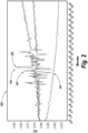
- FIG. 2 is a plot 200 of baseline results for two mixers, including the solvent mixing system of FIG. 1 , according to embodiments of the present disclosure.
- the upper three traces 201, 203, 205 correspond to three runs on a traditional mixing device without the tee/tube/mixer combination, while the lower trace 207 corresponds to the tee/tube/mixer system of the present disclosure.
- the bottom baseline trace 207 which corresponds to the solvent mixing system of this disclosure, has significantly reduced noise compared to the traces 201, 203, 205 of the traditional systems. This noise reduction can significantly improve peak integration.
- the top three traces 201, 203, 205 corresponding to a previous mixer system have significantly higher noise, especially in the time frame between 12 and 20 minutes. According to these previous techniques, if a chromatography peak lands between minute 12 and minute 20, peak integration may be very difficult and results may be compromised.
- FIG. 3A shows a comparison plot 300 of retention time standard deviation for two traditional systems, and the solvent mixing system of FIG. 1 , according to embodiments of the present disclosure.
- the retention time standard deviation for a system using a different style mixer is illustrated at 303, while the retention time standard deviation for another system using a different mixer is illustrated at 305.
- the retention time standard deviation for the tee/tube/mixer system of the present disclosure is illustrated at 301.
- the mixing system according to the present disclosure which includes a 50 uL mixing tee, a centrifugal mixing path, and a single input mixer, demonstrates a significantly lower retention time standard deviation 301. This decrease in retention time standard deviation can be the result of the combination of the three elements disclosed herein, and increased performance by the single input mixer.
- the comparison was performed using a flow rate of 0.2 mL/min.
- FIGS. 3B-3D show a comparison of baseline results for three different mixers, including the solvent mixing system of FIG. 1 , according to embodiments of the present disclosure.
- the baseline results for a first different system design are illustrated in FIG. 3B
- the baseline results for a second different system are illustrated in FIG. 3C
- the baseline results for the mixing system according to the present disclosure are illustrated in FIG. 3D .
- the baselines illustrated in FIGS. 3B and 3C are not necessarily noisy, they are significantly erratic and include substantial drift. This makes peak integration difficult.
- the baseline of the present system illustrated in FIG. 3D eliminates some of this unwanted behavior.
- FIG. 4 illustrates another example solvent mixing system 400, according to embodiments of the present disclosure.
- the solvent mixing system 400 includes a tee 401, a centrifugal mixing path 403 having a number of coils 402, and a mixer 405 arranged in series.
- the mixing tee 401 operates as a low volume, high frequency, first in first out (FIFO) mixing point with an internal mixing volume of about 0.045 uL.
- the mixing tee 401 has an internal mixing volume between about 0.005 to 3.000 uL, and can cover a range of tubing having inner diameters between about 0.003 to 0.060 inches with a common length of about 0.045 inches.
- the length could be between about 0.010 to 6 inches, depending on the constraints of the system.
- the mixing tee 401 includes at least two solvent input ports 407 and a solvent output port 409 in fluid communication with one another and configured to eliminate stratification of at least two solvent flow streams.
- the centrifugal mixing path 403 is in fluid communication with the output port 409, and includes a number of coils 102 that can impart a centrifugal force to a combined solvent flow stream received from the mixing tee 401. When passing through the coils 402 of the centrifugal mixing path 403, centrifugal force creates turbulence in the combined solvent stream, adding additional packet mixing.
- the centrifugal mixing path 403 has an inner diameter between about 0.0005 to about 0.090 inches. In one particular embodiment, the inner diameter of the centrifugal mixing path 403 is about 0.005 inches.
- the centrifugal mixing path 403 can include a single coil, or multiple coils, depending on the application, and the number and compactness of the coils can be dependent upon the solvents being mixed, or other application specific factors.
- the combined solvent from the mixing tee 401 can be pumped through the centrifugal mixing path 403 at a velocity between about 150 to 17,000 inch/min.
- the blending mixer 405 includes a low frequency single inlet mixer located downstream of the coiled centrifugal mixing path 403.
- the blending mixer 405 can be a low frequency mixer that can operate in a range between 0.5 to 80.0 cycles/minute.
- the blending mixer 405 can have a beaded or a diffusion bonded mixing chamber with multiple bore channels to create solvent blending, in some embodiments.
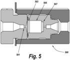
- FIG. 5 illustrates an example single inlet mixer 500, according to embodiments of the present disclosure.
- the mixer 500 includes a single input 501 that is in fluid communication with the centrifugal mixing path.
- the input 501 can be made of titanium, stainless steel or any suitable material for chemical compatibility according to some embodiments.
- the mixer 500 also includes a first filter/retainer 503 upstream of a mixing chamber 505 and a second filter/retainer 507 downstream of the mixing chamber 505.
- the mixer 500 can be a 100 uL mixer.
- the mixing chamber 505 can be a beaded mixing chamber or a diffusion bonded mixing chamber multiple bore channels to create solvent blending, according to some embodiments. Without the need for a two-input mixer, there are no voids which create stratification among the solvent stream.
- FIG. 6 is a flow chart illustrating an example method 600 for mixing solvent streams, according to an embodiment of the present disclosure.
- the method begins with directing 601 at least two solvent flow streams to a low volume mixing tee.
- the method then proceeds with mixing 603 the solvent flow streams within the low volume mixing tee to create a combined solvent stream.
- mixing the solvent flow streams within the low volume mixing tee eliminates stratification of the solvent flow streams.
- the mixing tee has an internal mixing volume between about 0.005 to 3.000 uL, and can cover a range of tubing having inner diameters between about 0.003 to 0.060 inches with a common length of about 0.045 inches. In some embodiments, the length could be between about 0.010 inches to about 6 inches, depending on the constraints of the system.
- the method continues with guiding 605 the combined solvent stream through a coiled centrifugal mixing path to impart a centrifugal force to the combined solvent stream.
- the centrifugal mixing path is contoured and shaped to impart a centrifugal force to a high velocity solvent mixture passing between the mixing path inlet and the mixing path outlet at a velocity between about 150 to 17,000 inch/min.
- the centrifugal mixing path has an inner diameter between about 0.0005 to about 0.090 inches. In one example embodiment, the inner diameter of the centrifugal mixing path is about 0.005 inches.
- the mixer design disclosed herein can be scaled for low micro flow rates at about 10 uL/min, or high flow applications up to about 1,000 mL/min.
- the method continues with further mixing 607 the combined solvent stream using a low frequency blending mixer located downstream of the coiled centrifugal mixing path.
- the blending mixer can operate in a range between 0.5 to 80.0 cycles/minute.
- the blending mixer is a single inlet mixer that operates at about 10 cycles/minute.
- further mixing the combined solvent stream using the blending mixer includes filtering the solvent stream using a first filter located downstream of a mixer input port, mixing the solvent stream within a mixing chamber, and filtering the solvent stream using a second filter located downstream of the mixing chamber.
- Exemplary flowcharts are provided herein for illustrative purposes and are nonlimiting examples of methods.
- One of ordinary skill in the art will recognize that exemplary methods may include more or fewer steps than those illustrated in the exemplary flowcharts, and that the operations in the exemplary flowcharts may be performed in a different order than the order shown.
- exemplary embodiments within this disclosure have been shown and described with references to particular embodiments, those of ordinary skill in the art will understand that various substitutions and alterations in form and detail may be made without departing from the scope of the present disclosure. Further still, other aspects, functions and advantages are also within the scope of the present disclosure.
Landscapes
- Chemical & Material Sciences (AREA)
- Chemical Kinetics & Catalysis (AREA)
- Dispersion Chemistry (AREA)
- Analytical Chemistry (AREA)
Applications Claiming Priority (3)
| Application Number | Priority Date | Filing Date | Title |
|---|---|---|---|
| US202063017154P | 2020-04-29 | 2020-04-29 | |
| PCT/IB2021/053478 WO2021220164A1 (en) | 2020-04-29 | 2021-04-27 | System and method for solvent mixing in a chromatography system |
| EP21723387.3A EP4142924B1 (de) | 2020-04-29 | 2021-04-27 | System und verfahren zum mischen von lösungsmitteln in einem chromatographiesystem |
Related Parent Applications (1)
| Application Number | Title | Priority Date | Filing Date |
|---|---|---|---|
| EP21723387.3A Division EP4142924B1 (de) | 2020-04-29 | 2021-04-27 | System und verfahren zum mischen von lösungsmitteln in einem chromatographiesystem |
Publications (2)
| Publication Number | Publication Date |
|---|---|
| EP4450152A2 true EP4450152A2 (de) | 2024-10-23 |
| EP4450152A3 EP4450152A3 (de) | 2025-01-01 |
Family
ID=75787152
Family Applications (2)
| Application Number | Title | Priority Date | Filing Date |
|---|---|---|---|
| EP21723387.3A Active EP4142924B1 (de) | 2020-04-29 | 2021-04-27 | System und verfahren zum mischen von lösungsmitteln in einem chromatographiesystem |
| EP24195484.1A Pending EP4450152A3 (de) | 2020-04-29 | 2021-04-27 | System und verfahren zum mischen von lösungsmitteln in einem chromatographiesystem |
Family Applications Before (1)
| Application Number | Title | Priority Date | Filing Date |
|---|---|---|---|
| EP21723387.3A Active EP4142924B1 (de) | 2020-04-29 | 2021-04-27 | System und verfahren zum mischen von lösungsmitteln in einem chromatographiesystem |
Country Status (4)
| Country | Link |
|---|---|
| US (2) | US12059659B2 (de) |
| EP (2) | EP4142924B1 (de) |
| CN (1) | CN115461139A (de) |
| WO (1) | WO2021220164A1 (de) |
Family Cites Families (12)
| Publication number | Priority date | Publication date | Assignee | Title |
|---|---|---|---|---|
| DE2719956C2 (de) * | 1977-05-04 | 1982-12-02 | Bayer Ag, 5090 Leverkusen | Vorrichtung zum Mischen, Reagieren und Ausdampfen |
| US4501501A (en) * | 1983-03-04 | 1985-02-26 | E. I. Du Pont De Nemours And Company | Process for dispersing solids in liquid media |
| WO2006017039A1 (en) | 2004-07-13 | 2006-02-16 | Waters Investments Limited | Fluid mixer assembly |
| JP4590558B2 (ja) * | 2005-05-20 | 2010-12-01 | 国立大学法人 東京大学 | 流体混合装置 |
| CN101666784B (zh) * | 2008-09-05 | 2012-09-19 | 华东电力试验研究院有限公司 | 色谱仪校验装置 |
| US10054569B2 (en) * | 2010-10-29 | 2018-08-21 | Thermo Finnigan Llc | Method and system for liquid chromatography fluidic monitoring |
| US9194780B2 (en) * | 2010-12-15 | 2015-11-24 | Dna Medicine Institute, Inc. | Microfluidic passive mixing chip |
| CN203043864U (zh) * | 2013-01-15 | 2013-07-10 | 大连保税区荣昌消防设备工程有限公司 | 一种多用途水与化学品混合系统 |
| US20150131405A1 (en) * | 2013-11-08 | 2015-05-14 | Xerox Corporation | Magnetic mixing for continuous latex preparation |
| JP6419745B2 (ja) | 2016-03-15 | 2018-11-07 | 株式会社東芝 | ミキサ構造、流体通路装置、および処理装置 |
| JP6290366B1 (ja) * | 2016-12-21 | 2018-03-07 | 東芝ライフスタイル株式会社 | 微細気泡発生器、微細気泡発生器を備えた家電機器 |
| CN208287831U (zh) * | 2018-04-04 | 2018-12-28 | 西安工程大学 | 一种用于流体均化混合的装置 |
-
2021
- 2021-04-27 US US17/241,255 patent/US12059659B2/en active Active
- 2021-04-27 CN CN202180031759.4A patent/CN115461139A/zh active Pending
- 2021-04-27 WO PCT/IB2021/053478 patent/WO2021220164A1/en not_active Ceased
- 2021-04-27 EP EP21723387.3A patent/EP4142924B1/de active Active
- 2021-04-27 EP EP24195484.1A patent/EP4450152A3/de active Pending
-
2024
- 2024-07-15 US US18/772,812 patent/US20240367123A1/en active Pending
Also Published As
| Publication number | Publication date |
|---|---|
| US20240367123A1 (en) | 2024-11-07 |
| WO2021220164A1 (en) | 2021-11-04 |
| CN115461139A (zh) | 2022-12-09 |
| EP4142924B1 (de) | 2024-08-28 |
| EP4450152A3 (de) | 2025-01-01 |
| US20210339211A1 (en) | 2021-11-04 |
| EP4142924A1 (de) | 2023-03-08 |
| US12059659B2 (en) | 2024-08-13 |
Similar Documents
| Publication | Publication Date | Title |
|---|---|---|
| JPH11253775A (ja) | ミキサー装置 | |
| US4506987A (en) | High pressure liquid chromatographic gradient mixer | |
| CN108956788B (zh) | 用于多维液体分析的阀和分流系统 | |
| CN101680861B (zh) | 流量分配阀 | |
| EP3678764B1 (de) | Flüssigkeitsmischer | |
| CN101809440B (zh) | 用于为高效液相色谱生成微流量和纳流量流动相梯度的设备 | |
| CN111032202A (zh) | 流体混合器 | |
| CN108351330B (zh) | 用于交叉流进样色谱法的系统、方法和设备 | |
| CN104676047B (zh) | 进样阀 | |
| EP4142924B1 (de) | System und verfahren zum mischen von lösungsmitteln in einem chromatographiesystem | |
| EP2703809A2 (de) | Vorrichtung zur Herstellung der mobilen Phase für die Flüssigkeitschromatographie | |
| WO2006017039A1 (en) | Fluid mixer assembly | |
| US20210156826A1 (en) | Sample injection for liquid chromatography using split solvent flow | |
| US6780325B1 (en) | Diffusion promoting apparatus for low flow velocity gradient high-speed liquid chromatography | |
| US12551858B2 (en) | Passive solvent mixer for liquid chromatography | |
| Salman et al. | Sample pulse broadening in Taylor flow microchannels for screening applications | |
| CN104730180A (zh) | 一种具有混合比例修正功能的液相色谱仪 | |
| JP6672781B2 (ja) | 流路機構及びこれを備えた液体クロマトグラフ | |
| CN114159998A (zh) | 试剂混合装置及液相色谱仪 | |
| EP4341681B1 (de) | Split-flow-mischer mit gleicher dispersion | |
| CN223697406U (zh) | 一种应用于液相色谱仪的流动相混合器 | |
| WO2025199274A1 (en) | Liquid chromatography system configuration | |
| RU50432U1 (ru) | Гидродинамический смеситель | |
| GB2641573A (en) | Liquid separation mass spectrometer system |
Legal Events
| Date | Code | Title | Description |
|---|---|---|---|
| PUAI | Public reference made under article 153(3) epc to a published international application that has entered the european phase |
Free format text: ORIGINAL CODE: 0009012 |
|
| STAA | Information on the status of an ep patent application or granted ep patent |
Free format text: STATUS: THE APPLICATION HAS BEEN PUBLISHED |
|
| AC | Divisional application: reference to earlier application |
Ref document number: 4142924 Country of ref document: EP Kind code of ref document: P |
|
| AK | Designated contracting states |
Kind code of ref document: A2 Designated state(s): AL AT BE BG CH CY CZ DE DK EE ES FI FR GB GR HR HU IE IS IT LI LT LU LV MC MK MT NL NO PL PT RO RS SE SI SK SM TR |
|
| REG | Reference to a national code |
Ref country code: DE Ref legal event code: R079 Free format text: PREVIOUS MAIN CLASS: B01F0033820000 Ipc: B01F0025230000 |
|
| PUAL | Search report despatched |
Free format text: ORIGINAL CODE: 0009013 |
|
| AK | Designated contracting states |
Kind code of ref document: A3 Designated state(s): AL AT BE BG CH CY CZ DE DK EE ES FI FR GB GR HR HU IE IS IT LI LT LU LV MC MK MT NL NO PL PT RO RS SE SI SK SM TR |
|
| RIC1 | Information provided on ipc code assigned before grant |
Ipc: B01F 33/82 20220101ALI20241126BHEP Ipc: B01F 25/452 20220101ALI20241126BHEP Ipc: B01F 25/433 20220101ALI20241126BHEP Ipc: B01F 25/23 20220101AFI20241126BHEP |
|
| STAA | Information on the status of an ep patent application or granted ep patent |
Free format text: STATUS: REQUEST FOR EXAMINATION WAS MADE |
|
| 17P | Request for examination filed |
Effective date: 20250630 |
|
| STAA | Information on the status of an ep patent application or granted ep patent |
Free format text: STATUS: EXAMINATION IS IN PROGRESS |
|
| 17Q | First examination report despatched |
Effective date: 20260326 |