EP4450144A1 - Verfahren zur verflüssigung von kohlendioxid - Google Patents
Verfahren zur verflüssigung von kohlendioxid Download PDFInfo
- Publication number
- EP4450144A1 EP4450144A1 EP23169225.2A EP23169225A EP4450144A1 EP 4450144 A1 EP4450144 A1 EP 4450144A1 EP 23169225 A EP23169225 A EP 23169225A EP 4450144 A1 EP4450144 A1 EP 4450144A1
- Authority
- EP
- European Patent Office
- Prior art keywords
- gas
- carbon dioxide
- unit
- stage
- filtration
- Prior art date
- Legal status (The legal status is an assumption and is not a legal conclusion. Google has not performed a legal analysis and makes no representation as to the accuracy of the status listed.)
- Granted
Links
Images

Classifications
-
- B—PERFORMING OPERATIONS; TRANSPORTING
- B01—PHYSICAL OR CHEMICAL PROCESSES OR APPARATUS IN GENERAL
- B01D—SEPARATION
- B01D53/00—Separation of gases or vapours; Recovering vapours of volatile solvents from gases; Chemical or biological purification of waste gases, e.g. engine exhaust gases, smoke, fumes, flue gases, aerosols
- B01D53/002—Separation of gases or vapours; Recovering vapours of volatile solvents from gases; Chemical or biological purification of waste gases, e.g. engine exhaust gases, smoke, fumes, flue gases, aerosols by condensation
-
- B—PERFORMING OPERATIONS; TRANSPORTING
- B01—PHYSICAL OR CHEMICAL PROCESSES OR APPARATUS IN GENERAL
- B01D—SEPARATION
- B01D53/00—Separation of gases or vapours; Recovering vapours of volatile solvents from gases; Chemical or biological purification of waste gases, e.g. engine exhaust gases, smoke, fumes, flue gases, aerosols
- B01D53/005—Separation of gases or vapours; Recovering vapours of volatile solvents from gases; Chemical or biological purification of waste gases, e.g. engine exhaust gases, smoke, fumes, flue gases, aerosols by heat treatment
-
- B—PERFORMING OPERATIONS; TRANSPORTING
- B01—PHYSICAL OR CHEMICAL PROCESSES OR APPARATUS IN GENERAL
- B01D—SEPARATION
- B01D53/00—Separation of gases or vapours; Recovering vapours of volatile solvents from gases; Chemical or biological purification of waste gases, e.g. engine exhaust gases, smoke, fumes, flue gases, aerosols
- B01D53/22—Separation of gases or vapours; Recovering vapours of volatile solvents from gases; Chemical or biological purification of waste gases, e.g. engine exhaust gases, smoke, fumes, flue gases, aerosols by diffusion
- B01D53/229—Integrated processes (Diffusion and at least one other process, e.g. adsorption, absorption)
-
- C—CHEMISTRY; METALLURGY
- C01—INORGANIC CHEMISTRY
- C01B—NON-METALLIC ELEMENTS; COMPOUNDS THEREOF; METALLOIDS OR COMPOUNDS THEREOF NOT COVERED BY SUBCLASS C01C
- C01B32/00—Carbon; Compounds thereof
- C01B32/50—Carbon dioxide
-
- F—MECHANICAL ENGINEERING; LIGHTING; HEATING; WEAPONS; BLASTING
- F25—REFRIGERATION OR COOLING; COMBINED HEATING AND REFRIGERATION SYSTEMS; HEAT PUMP SYSTEMS; MANUFACTURE OR STORAGE OF ICE; LIQUEFACTION SOLIDIFICATION OF GASES
- F25J—LIQUEFACTION, SOLIDIFICATION OR SEPARATION OF GASES OR GASEOUS OR LIQUEFIED GASEOUS MIXTURES BY PRESSURE AND COLD TREATMENT OR BY BRINGING THEM INTO THE SUPERCRITICAL STATE
- F25J3/00—Processes or apparatus for separating the constituents of gaseous or liquefied gaseous mixtures involving the use of liquefaction or solidification
- F25J3/02—Processes or apparatus for separating the constituents of gaseous or liquefied gaseous mixtures involving the use of liquefaction or solidification by rectification, i.e. by continuous interchange of heat and material between a vapour stream and a liquid stream
- F25J3/0204—Processes or apparatus for separating the constituents of gaseous or liquefied gaseous mixtures involving the use of liquefaction or solidification by rectification, i.e. by continuous interchange of heat and material between a vapour stream and a liquid stream characterised by the feed stream
- F25J3/0209—Natural gas or substitute natural gas
-
- F—MECHANICAL ENGINEERING; LIGHTING; HEATING; WEAPONS; BLASTING
- F25—REFRIGERATION OR COOLING; COMBINED HEATING AND REFRIGERATION SYSTEMS; HEAT PUMP SYSTEMS; MANUFACTURE OR STORAGE OF ICE; LIQUEFACTION SOLIDIFICATION OF GASES
- F25J—LIQUEFACTION, SOLIDIFICATION OR SEPARATION OF GASES OR GASEOUS OR LIQUEFIED GASEOUS MIXTURES BY PRESSURE AND COLD TREATMENT OR BY BRINGING THEM INTO THE SUPERCRITICAL STATE
- F25J3/00—Processes or apparatus for separating the constituents of gaseous or liquefied gaseous mixtures involving the use of liquefaction or solidification
- F25J3/02—Processes or apparatus for separating the constituents of gaseous or liquefied gaseous mixtures involving the use of liquefaction or solidification by rectification, i.e. by continuous interchange of heat and material between a vapour stream and a liquid stream
- F25J3/0228—Processes or apparatus for separating the constituents of gaseous or liquefied gaseous mixtures involving the use of liquefaction or solidification by rectification, i.e. by continuous interchange of heat and material between a vapour stream and a liquid stream characterised by the separated product stream
- F25J3/0233—Processes or apparatus for separating the constituents of gaseous or liquefied gaseous mixtures involving the use of liquefaction or solidification by rectification, i.e. by continuous interchange of heat and material between a vapour stream and a liquid stream characterised by the separated product stream separation of CnHm with 1 carbon atom or more
-
- F—MECHANICAL ENGINEERING; LIGHTING; HEATING; WEAPONS; BLASTING
- F25—REFRIGERATION OR COOLING; COMBINED HEATING AND REFRIGERATION SYSTEMS; HEAT PUMP SYSTEMS; MANUFACTURE OR STORAGE OF ICE; LIQUEFACTION SOLIDIFICATION OF GASES
- F25J—LIQUEFACTION, SOLIDIFICATION OR SEPARATION OF GASES OR GASEOUS OR LIQUEFIED GASEOUS MIXTURES BY PRESSURE AND COLD TREATMENT OR BY BRINGING THEM INTO THE SUPERCRITICAL STATE
- F25J3/00—Processes or apparatus for separating the constituents of gaseous or liquefied gaseous mixtures involving the use of liquefaction or solidification
- F25J3/02—Processes or apparatus for separating the constituents of gaseous or liquefied gaseous mixtures involving the use of liquefaction or solidification by rectification, i.e. by continuous interchange of heat and material between a vapour stream and a liquid stream
- F25J3/0228—Processes or apparatus for separating the constituents of gaseous or liquefied gaseous mixtures involving the use of liquefaction or solidification by rectification, i.e. by continuous interchange of heat and material between a vapour stream and a liquid stream characterised by the separated product stream
- F25J3/0266—Processes or apparatus for separating the constituents of gaseous or liquefied gaseous mixtures involving the use of liquefaction or solidification by rectification, i.e. by continuous interchange of heat and material between a vapour stream and a liquid stream characterised by the separated product stream separation of carbon dioxide
-
- F—MECHANICAL ENGINEERING; LIGHTING; HEATING; WEAPONS; BLASTING
- F25—REFRIGERATION OR COOLING; COMBINED HEATING AND REFRIGERATION SYSTEMS; HEAT PUMP SYSTEMS; MANUFACTURE OR STORAGE OF ICE; LIQUEFACTION SOLIDIFICATION OF GASES
- F25J—LIQUEFACTION, SOLIDIFICATION OR SEPARATION OF GASES OR GASEOUS OR LIQUEFIED GASEOUS MIXTURES BY PRESSURE AND COLD TREATMENT OR BY BRINGING THEM INTO THE SUPERCRITICAL STATE
- F25J3/00—Processes or apparatus for separating the constituents of gaseous or liquefied gaseous mixtures involving the use of liquefaction or solidification
- F25J3/02—Processes or apparatus for separating the constituents of gaseous or liquefied gaseous mixtures involving the use of liquefaction or solidification by rectification, i.e. by continuous interchange of heat and material between a vapour stream and a liquid stream
- F25J3/0295—Start-up or control of the process; Details of the apparatus used, e.g. sieve plates, packings
-
- B—PERFORMING OPERATIONS; TRANSPORTING
- B01—PHYSICAL OR CHEMICAL PROCESSES OR APPARATUS IN GENERAL
- B01D—SEPARATION
- B01D2256/00—Main component in the product gas stream after treatment
- B01D2256/22—Carbon dioxide
-
- B—PERFORMING OPERATIONS; TRANSPORTING
- B01—PHYSICAL OR CHEMICAL PROCESSES OR APPARATUS IN GENERAL
- B01D—SEPARATION
- B01D2257/00—Components to be removed
- B01D2257/70—Organic compounds not provided for in groups B01D2257/00 - B01D2257/602
- B01D2257/702—Hydrocarbons
- B01D2257/7022—Aliphatic hydrocarbons
- B01D2257/7025—Methane
-
- B—PERFORMING OPERATIONS; TRANSPORTING
- B01—PHYSICAL OR CHEMICAL PROCESSES OR APPARATUS IN GENERAL
- B01D—SEPARATION
- B01D2258/00—Sources of waste gases
- B01D2258/02—Other waste gases
- B01D2258/0233—Other waste gases from cement factories
-
- B—PERFORMING OPERATIONS; TRANSPORTING
- B01—PHYSICAL OR CHEMICAL PROCESSES OR APPARATUS IN GENERAL
- B01D—SEPARATION
- B01D2258/00—Sources of waste gases
- B01D2258/05—Biogas
-
- B—PERFORMING OPERATIONS; TRANSPORTING
- B01—PHYSICAL OR CHEMICAL PROCESSES OR APPARATUS IN GENERAL
- B01D—SEPARATION
- B01D53/00—Separation of gases or vapours; Recovering vapours of volatile solvents from gases; Chemical or biological purification of waste gases, e.g. engine exhaust gases, smoke, fumes, flue gases, aerosols
- B01D53/26—Drying gases or vapours
-
- F—MECHANICAL ENGINEERING; LIGHTING; HEATING; WEAPONS; BLASTING
- F25—REFRIGERATION OR COOLING; COMBINED HEATING AND REFRIGERATION SYSTEMS; HEAT PUMP SYSTEMS; MANUFACTURE OR STORAGE OF ICE; LIQUEFACTION SOLIDIFICATION OF GASES
- F25J—LIQUEFACTION, SOLIDIFICATION OR SEPARATION OF GASES OR GASEOUS OR LIQUEFIED GASEOUS MIXTURES BY PRESSURE AND COLD TREATMENT OR BY BRINGING THEM INTO THE SUPERCRITICAL STATE
- F25J2200/00—Processes or apparatus using separation by rectification
- F25J2200/02—Processes or apparatus using separation by rectification in a single pressure main column system
-
- F—MECHANICAL ENGINEERING; LIGHTING; HEATING; WEAPONS; BLASTING
- F25—REFRIGERATION OR COOLING; COMBINED HEATING AND REFRIGERATION SYSTEMS; HEAT PUMP SYSTEMS; MANUFACTURE OR STORAGE OF ICE; LIQUEFACTION SOLIDIFICATION OF GASES
- F25J—LIQUEFACTION, SOLIDIFICATION OR SEPARATION OF GASES OR GASEOUS OR LIQUEFIED GASEOUS MIXTURES BY PRESSURE AND COLD TREATMENT OR BY BRINGING THEM INTO THE SUPERCRITICAL STATE
- F25J2200/00—Processes or apparatus using separation by rectification
- F25J2200/74—Refluxing the column with at least a part of the partially condensed overhead gas
-
- F—MECHANICAL ENGINEERING; LIGHTING; HEATING; WEAPONS; BLASTING
- F25—REFRIGERATION OR COOLING; COMBINED HEATING AND REFRIGERATION SYSTEMS; HEAT PUMP SYSTEMS; MANUFACTURE OR STORAGE OF ICE; LIQUEFACTION SOLIDIFICATION OF GASES
- F25J—LIQUEFACTION, SOLIDIFICATION OR SEPARATION OF GASES OR GASEOUS OR LIQUEFIED GASEOUS MIXTURES BY PRESSURE AND COLD TREATMENT OR BY BRINGING THEM INTO THE SUPERCRITICAL STATE
- F25J2205/00—Processes or apparatus using other separation and/or other processing means
- F25J2205/40—Processes or apparatus using other separation and/or other processing means using hybrid system, i.e. combining cryogenic and non-cryogenic separation techniques
-
- F—MECHANICAL ENGINEERING; LIGHTING; HEATING; WEAPONS; BLASTING
- F25—REFRIGERATION OR COOLING; COMBINED HEATING AND REFRIGERATION SYSTEMS; HEAT PUMP SYSTEMS; MANUFACTURE OR STORAGE OF ICE; LIQUEFACTION SOLIDIFICATION OF GASES
- F25J—LIQUEFACTION, SOLIDIFICATION OR SEPARATION OF GASES OR GASEOUS OR LIQUEFIED GASEOUS MIXTURES BY PRESSURE AND COLD TREATMENT OR BY BRINGING THEM INTO THE SUPERCRITICAL STATE
- F25J2205/00—Processes or apparatus using other separation and/or other processing means
- F25J2205/80—Processes or apparatus using other separation and/or other processing means using membrane, i.e. including a permeation step
-
- F—MECHANICAL ENGINEERING; LIGHTING; HEATING; WEAPONS; BLASTING
- F25—REFRIGERATION OR COOLING; COMBINED HEATING AND REFRIGERATION SYSTEMS; HEAT PUMP SYSTEMS; MANUFACTURE OR STORAGE OF ICE; LIQUEFACTION SOLIDIFICATION OF GASES
- F25J—LIQUEFACTION, SOLIDIFICATION OR SEPARATION OF GASES OR GASEOUS OR LIQUEFIED GASEOUS MIXTURES BY PRESSURE AND COLD TREATMENT OR BY BRINGING THEM INTO THE SUPERCRITICAL STATE
- F25J2210/00—Processes characterised by the type or other details of the feed stream
- F25J2210/04—Mixing or blending of fluids with the feed stream
-
- F—MECHANICAL ENGINEERING; LIGHTING; HEATING; WEAPONS; BLASTING
- F25—REFRIGERATION OR COOLING; COMBINED HEATING AND REFRIGERATION SYSTEMS; HEAT PUMP SYSTEMS; MANUFACTURE OR STORAGE OF ICE; LIQUEFACTION SOLIDIFICATION OF GASES
- F25J—LIQUEFACTION, SOLIDIFICATION OR SEPARATION OF GASES OR GASEOUS OR LIQUEFIED GASEOUS MIXTURES BY PRESSURE AND COLD TREATMENT OR BY BRINGING THEM INTO THE SUPERCRITICAL STATE
- F25J2210/00—Processes characterised by the type or other details of the feed stream
- F25J2210/66—Landfill or fermentation off-gas, e.g. "Bio-gas"
-
- F—MECHANICAL ENGINEERING; LIGHTING; HEATING; WEAPONS; BLASTING
- F25—REFRIGERATION OR COOLING; COMBINED HEATING AND REFRIGERATION SYSTEMS; HEAT PUMP SYSTEMS; MANUFACTURE OR STORAGE OF ICE; LIQUEFACTION SOLIDIFICATION OF GASES
- F25J—LIQUEFACTION, SOLIDIFICATION OR SEPARATION OF GASES OR GASEOUS OR LIQUEFIED GASEOUS MIXTURES BY PRESSURE AND COLD TREATMENT OR BY BRINGING THEM INTO THE SUPERCRITICAL STATE
- F25J2215/00—Processes characterised by the type or other details of the product stream
- F25J2215/04—Recovery of liquid products
-
- F—MECHANICAL ENGINEERING; LIGHTING; HEATING; WEAPONS; BLASTING
- F25—REFRIGERATION OR COOLING; COMBINED HEATING AND REFRIGERATION SYSTEMS; HEAT PUMP SYSTEMS; MANUFACTURE OR STORAGE OF ICE; LIQUEFACTION SOLIDIFICATION OF GASES
- F25J—LIQUEFACTION, SOLIDIFICATION OR SEPARATION OF GASES OR GASEOUS OR LIQUEFIED GASEOUS MIXTURES BY PRESSURE AND COLD TREATMENT OR BY BRINGING THEM INTO THE SUPERCRITICAL STATE
- F25J2220/00—Processes or apparatus involving steps for the removal of impurities
- F25J2220/02—Separating impurities in general from the feed stream
-
- F—MECHANICAL ENGINEERING; LIGHTING; HEATING; WEAPONS; BLASTING
- F25—REFRIGERATION OR COOLING; COMBINED HEATING AND REFRIGERATION SYSTEMS; HEAT PUMP SYSTEMS; MANUFACTURE OR STORAGE OF ICE; LIQUEFACTION SOLIDIFICATION OF GASES
- F25J—LIQUEFACTION, SOLIDIFICATION OR SEPARATION OF GASES OR GASEOUS OR LIQUEFIED GASEOUS MIXTURES BY PRESSURE AND COLD TREATMENT OR BY BRINGING THEM INTO THE SUPERCRITICAL STATE
- F25J2230/00—Processes or apparatus involving steps for increasing the pressure of gaseous process streams
- F25J2230/30—Compression of the feed stream
-
- F—MECHANICAL ENGINEERING; LIGHTING; HEATING; WEAPONS; BLASTING
- F25—REFRIGERATION OR COOLING; COMBINED HEATING AND REFRIGERATION SYSTEMS; HEAT PUMP SYSTEMS; MANUFACTURE OR STORAGE OF ICE; LIQUEFACTION SOLIDIFICATION OF GASES
- F25J—LIQUEFACTION, SOLIDIFICATION OR SEPARATION OF GASES OR GASEOUS OR LIQUEFIED GASEOUS MIXTURES BY PRESSURE AND COLD TREATMENT OR BY BRINGING THEM INTO THE SUPERCRITICAL STATE
- F25J2245/00—Processes or apparatus involving steps for recycling of process streams
- F25J2245/02—Recycle of a stream in general, e.g. a by-pass stream
-
- F—MECHANICAL ENGINEERING; LIGHTING; HEATING; WEAPONS; BLASTING
- F25—REFRIGERATION OR COOLING; COMBINED HEATING AND REFRIGERATION SYSTEMS; HEAT PUMP SYSTEMS; MANUFACTURE OR STORAGE OF ICE; LIQUEFACTION SOLIDIFICATION OF GASES
- F25J—LIQUEFACTION, SOLIDIFICATION OR SEPARATION OF GASES OR GASEOUS OR LIQUEFIED GASEOUS MIXTURES BY PRESSURE AND COLD TREATMENT OR BY BRINGING THEM INTO THE SUPERCRITICAL STATE
- F25J2270/00—Refrigeration techniques used
- F25J2270/12—External refrigeration with liquid vaporising loop
-
- F—MECHANICAL ENGINEERING; LIGHTING; HEATING; WEAPONS; BLASTING
- F25—REFRIGERATION OR COOLING; COMBINED HEATING AND REFRIGERATION SYSTEMS; HEAT PUMP SYSTEMS; MANUFACTURE OR STORAGE OF ICE; LIQUEFACTION SOLIDIFICATION OF GASES
- F25J—LIQUEFACTION, SOLIDIFICATION OR SEPARATION OF GASES OR GASEOUS OR LIQUEFIED GASEOUS MIXTURES BY PRESSURE AND COLD TREATMENT OR BY BRINGING THEM INTO THE SUPERCRITICAL STATE
- F25J2270/00—Refrigeration techniques used
- F25J2270/90—External refrigeration, e.g. conventional closed-loop mechanical refrigeration unit using Freon or NH3, unspecified external refrigeration
- F25J2270/902—Details about the refrigeration cycle used, e.g. composition of refrigerant, arrangement of compressors or cascade, make up sources, use of reflux exchangers etc.
-
- F—MECHANICAL ENGINEERING; LIGHTING; HEATING; WEAPONS; BLASTING
- F25—REFRIGERATION OR COOLING; COMBINED HEATING AND REFRIGERATION SYSTEMS; HEAT PUMP SYSTEMS; MANUFACTURE OR STORAGE OF ICE; LIQUEFACTION SOLIDIFICATION OF GASES
- F25J—LIQUEFACTION, SOLIDIFICATION OR SEPARATION OF GASES OR GASEOUS OR LIQUEFIED GASEOUS MIXTURES BY PRESSURE AND COLD TREATMENT OR BY BRINGING THEM INTO THE SUPERCRITICAL STATE
- F25J2290/00—Other details not covered by groups F25J2200/00 - F25J2280/00
- F25J2290/42—Modularity, pre-fabrication of modules, assembling and erection, horizontal layout, i.e. plot plan, and vertical arrangement of parts of the cryogenic unit, e.g. of the cold box
-
- F—MECHANICAL ENGINEERING; LIGHTING; HEATING; WEAPONS; BLASTING
- F25—REFRIGERATION OR COOLING; COMBINED HEATING AND REFRIGERATION SYSTEMS; HEAT PUMP SYSTEMS; MANUFACTURE OR STORAGE OF ICE; LIQUEFACTION SOLIDIFICATION OF GASES
- F25J—LIQUEFACTION, SOLIDIFICATION OR SEPARATION OF GASES OR GASEOUS OR LIQUEFIED GASEOUS MIXTURES BY PRESSURE AND COLD TREATMENT OR BY BRINGING THEM INTO THE SUPERCRITICAL STATE
- F25J2290/00—Other details not covered by groups F25J2200/00 - F25J2280/00
- F25J2290/62—Details of storing a fluid in a tank
-
- Y—GENERAL TAGGING OF NEW TECHNOLOGICAL DEVELOPMENTS; GENERAL TAGGING OF CROSS-SECTIONAL TECHNOLOGIES SPANNING OVER SEVERAL SECTIONS OF THE IPC; TECHNICAL SUBJECTS COVERED BY FORMER USPC CROSS-REFERENCE ART COLLECTIONS [XRACs] AND DIGESTS
- Y02—TECHNOLOGIES OR APPLICATIONS FOR MITIGATION OR ADAPTATION AGAINST CLIMATE CHANGE
- Y02C—CAPTURE, STORAGE, SEQUESTRATION OR DISPOSAL OF GREENHOUSE GASES [GHG]
- Y02C20/00—Capture or disposal of greenhouse gases
- Y02C20/40—Capture or disposal of greenhouse gases of CO2
Definitions
- the present invention relates to a method for producing liquid carbon dioxide from a gas comprising more than 70% by volume of carbon dioxide.
- the invention also relates to a device for producing liquid carbon dioxide and its use.
- Methanization is a process of decomposition of organic matter. It consists of the fermentation of livestock effluents or by-products from the agri-food industry, the principle of which is as follows: the organic effluents are stored in a sealed tank called a "digester", in which they are subjected to the action of micro-organisms (bacteria) in the absence of oxygen (anaerobic fermentation) for a specific residence time (generally around 60 days). This process generates biogas, which includes, among other things, methane (CH 4 , in proportions of 50% to 70%), and carbon dioxide (COz) as well as an organic residue (called “digestate” used as fertilizer). Biogas can be transformed either into electricity or into gas and fuel for vehicles.
- Methanization represents a substantial economic interest; the biogas produced can replace natural gas in all its current uses: heat production, electricity production and fuel for vehicles, and the digestate is fully recovered, particularly in the form of fertilizer whose composition is much more complete than that of a chemical fertilizer.
- Methanization also has an environmental interest, because biogas is a renewable energy. Although its production and use generate pollutant emissions into the atmosphere (COz), these remain less significant than those of fossil fuels.
- the method according to the invention aims to recover a gas, a by-product of methanization.
- a gas mainly comprising carbon dioxide called “lean gas”
- the invention aims to recover this lean gas by isolating and purifying the carbon dioxide so as to obtain carbon dioxide in liquid form of food grade, or even pharmaceutical grade.
- the carbon dioxide produced can be used for example for the manufacture of sparkling water. It can be used in breweries. In the pharmaceutical field, it can be used for cryogenics. In the agricultural field, it can be used to heat greenhouses.
- the method according to the invention aims to recover carbon dioxide-rich gases, which are reaction by-products and which are generally sent to the atmosphere.
- the method according to the invention isolates the carbon dioxide present in these gases, the carbon dioxide is purified and then liquefied.
- This process according to the invention aims to obtain carbon dioxide of a very high level of purity.
- the liquefied carbon dioxide obtained can be of food grade, in compliance with the EIGA Doc 126-11 standard (appendix 1, page 6) or of pharmaceutical grade in compliance with the European Pharmacopoeia and GMP.
- This process has the advantage of being inexpensive in terms of energy and leading to good efficiency.
- This process can also have the advantage of recycling all of the other components of the gas.
- the method may further comprise a particle filtration step between steps a) and b).
- the method may further comprise a step of cooling the gas between steps h) and i).
- the gas containing more than 70% by volume of carbon dioxide may be a gas from a methanization unit, a gas from a biogas purification unit, a gas from a steam reforming unit, a gas from an oxycombustion unit, or a gas from a unit for recovering gases produced by a cement plant.
- the compressor (CP) may be a multi-stage compressor, equipped with at least two compressors mounted in series (CP201, CP202), and equipped with at least two heat exchangers (E211, E212 and E213, E214) mounted in series and positioned downstream of each compressor.
- the liquefiers (E105, E106) can be connected to cooling devices, comprising at least two cooling circuits mounted in cascade (33, 34).
- the separator (Sep) can be fluidically connected to a heat exchanger (E107), then to a filtration unit (F107) on membrane, a pipe (C4) connects the filtration unit (F107) to the pipe upstream of the booster (SP) so as to recycle the gas containing carbon dioxide.
- the pipe (C2) located at the outlet of the distillation column (DC) can be connected to a valve (V), then to a storage tank (STK), recovering the liquefied carbon dioxide.
- the device may comprise at least one filtration unit between the heat exchanger (E104) and the liquefier (E105).
- the device may comprise at least one filtration unit between a buffer tank (TK102) and heat exchanger (E104).
- TK102 buffer tank
- E104 heat exchanger
- the device may be arranged inside a container, preferably a shipping container.
- the invention finally relates to the use of the device for liquefying a gas coming from a methanization unit, a biogas purification unit, a steam reforming unit, an oxycombustion unit, a unit for recovering gases produced by a cement plant.
- heat exchanger means a device for transferring thermal energy from one fluid to another fluid, without mixing them.
- the heat flow passes through the exchange surface which separates the fluids.
- the raw material of the process is a gas comprising mainly carbon dioxide.
- the term mainly means a gas comprising more than 70% by volume of carbon dioxide relative to the total volume of the gas, preferably more than 80% by volume.
- the method according to the invention can also be implemented on very pure carbon dioxide gases.
- VOC volatile organic compounds
- the composition of the gas depends on the source process, i.e. the prior process.
- a gas from a cement plant does not have the same chemical composition as a gas from the purification of biogas generated by a methanizer.
- the gas temperature is preferably between 15°C and 90°C, preferably between 20°C and 40°C.
- the gas pressure is preferably close to atmospheric pressure, advantageously between 1 bar and 1.1 bar.
- the method according to the invention comprises the following fourteen consecutive steps: steps a) to n).
- the gas undergoes one or more activated carbon filtrations.
- the process comprises between one and five activated carbon filtration stages, and more particularly between two and three activated carbon filtration stages.
- the activated carbon filtration step aims to eliminate volatile organic compounds present in the gas.
- the gas thus filtered can then undergo one or more filtration stages, for example particle filtration so as to eliminate the particles of activated carbon potentially present in the gas, in particular the residues of activated carbon in powder form, and the dust following the previous activated carbon filtration stage(s).
- one or more filtration stages for example particle filtration so as to eliminate the particles of activated carbon potentially present in the gas, in particular the residues of activated carbon in powder form, and the dust following the previous activated carbon filtration stage(s).
- the particle filter can, for example, be a molecular sieve.
- the filtered gas undergoes one or more cooling stages using a heat exchanger. Thermal or heat energy is extracted from the gas using a cooling source.
- This cooling source can be selected from air via an air cooler, water or glycol water.
- the purpose of this step is to impose a temperature on the gas at the start of the process. Indeed, the temperature of the gas at the inlet of the process is variable. It fluctuates in particular depending on the type of process, which generates the gas.
- the cooling step(s) thus make it possible to reach a temperature of between 10 and 20°C, preferably between 10 and 15°C, advantageously 12°C.
- the method comprises two cooling stages, the first using air as a cooling fluid and the second using water as a cooling fluid.
- the method comprises two cooling stages, the first using air as a cooling fluid and the second using water as a cooling fluid and a particle filtration stage, preferably using a sieve, in order to eliminate dust between these two cooling stages.
- the gas then undergoes a pressure boosting step.
- the purpose of this step is to impose a pressure higher than atmospheric pressure at the inlet of the compressor used in step e).
- the booster sucks in the gas and compresses it to reach a pressure at the compressor outlet of between 1.05 and 1.40 bar.
- the gas then passes through a buffer tank, which has the function of stabilizing the gas pressure within the process.
- the buffer tank aims to dampen fluctuations in gas flow, which depend on the production process of this gas.
- This tank is positioned downstream of the booster and upstream of the compressor so that the pressure at the compressor inlet is constant.
- the gas then passes through one or more exchangers to be cooled before entering the compressor.
- the suppression step c) slightly warms the gas.
- the compression step e) causes a significant rise in temperature of the gas. By Therefore, it is advantageous to cool the gas before it enters the compressor so that the compression stage is as efficient as possible.
- This or these cooling stages make it possible to reach a temperature between 5 and 40°C, before the compressor enters.
- the method comprises two cooling steps, the first using water as the cooling fluid and the second using glycolated water as the cooling fluid.
- the gas pressure is between 1.05 and 1.40 bar.
- the gas pressure is between 15 and 25 bar.
- the gas must be compressed to at least a pressure higher than the triple point pressure of carbon dioxide, i.e. 5.18 bars, in order to avoid icing.
- the compression is carried out in at least two stages, using a multi-stage compressor.
- At each stage at the outlet of the compressor, at least two heat exchangers connected in series are used so as to recover at different temperature levels the energy generated by the compression of the gas.
- the cooling of the gas makes it possible to protect the compressor from possible overheating.
- an oil-free dry compressor is used. This avoids contamination of the gas with oil residues.
- the process uses a two-stage compressor.
- the gas temperature is between 110°C and 210°C, preferably between 150°C and 190°C.
- the gas temperature is between 150°C and 220°C.
- the at least two exchangers mounted in series make it possible to reduce this temperature range between 25 and 50°C.
- the gas is preferably at 206°C and 25 bars.
- the gas is saturated with humidity.
- the compressed gas undergoes one or more filtrations in order to eliminate condensates, dust and possibly impurities generated during compression.
- Filtration can be carried out on molecular sieves.
- the gas is then dried to eliminate any remaining traces of water and to reach a dew point temperature at the outlet of the drying device of between -65 and -45°C at 25 bars or a water content of less than 20 ppm.
- a zeolite selectively adsorbing water is used.
- the apparatus used to carry out this drying step can be equipped with two columns, one adsorbing the traces of humidity from the gas and the second allowing the desorption of water, i.e. the regeneration of the column. Cyclic and continuous operation of the two columns is preferred.
- This drying step is essential, both to meet food grade specifications and to avoid frost phenomena at the level of subsequent exchangers.
- the dried gas then undergoes one or more additional filtration steps to remove any traces of impurities. Filtration can be carried out on molecular sieves.
- the gas then passes through a buffer tank, which has the function of stabilizing the pressure within the process and homogenizing the composition of the gas.
- This tank is positioned downstream of the compressor so that the pressure at the compressor outlet is constant.
- the gas can still undergo one or more new filtration stages, with the presence of activated carbon, in order to eliminate any impurities.
- the aim is for the gas to be as pure as possible before the liquefaction stage i).
- the gas can then pass through one or more heat exchangers so as to cool it gradually.
- the method comprises a cooling step using a glycol water exchanger.
- the gas can still undergo one or more new stages of filtration, with the presence of activated carbon, in order to eliminate any possible impurities.
- the gas then passes through a liquefier allowing the carbon dioxide to change state. It changes from a gaseous state to a liquid state.
- the liquefier is an exchanger, which uses a refrigerant fluid.
- a two-phase fluid which contains liquefied carbon dioxide is obtained. It is at a temperature between -25°C and -35°C.
- the fluid undergoes a distillation step in order to isolate the carbon dioxide in liquefied form.
- the liquefied carbon dioxide is recovered at the bottom of the column, while the gas is recovered at the top of the column.
- the temperature within the column is between -18°C and -45°C at a pressure between 15 and 25 bars.
- the recovered carbon dioxide can be analyzed.
- the circuit may include a bypass valve. If the purity of the recovered liquid is not sufficient, the liquid can be sent to the atmosphere once heated. If the purity of the recovered liquid is satisfactory, the liquid can be sent directly to a storage tank or used.
- Liquefied carbon dioxide is recovered. It can be sent to a tank for storage. It can also be used directly for further application.
- the gas recovered at the top of the distillation column in step j) is a gas having a carbon dioxide content lower than that of the gas entering the process according to the invention.
- This gas comprises carbon dioxide, which has not liquefied during the process.
- This gas may optionally comprise oxygen, nitrogen, methane, hydrogen, carbon monoxide depending on the source of the initial gas.
- the gas then passes through a liquefier to be cooled to a temperature between -35°C and -45°C.
- This step allows the carbon dioxide, not yet liquefied and isolated at this stage of the process, to be liquefied.
- This step constitutes the second liquefaction step. At the end of this step, a two-phase fluid is obtained.
- the two-phase fluid from the previous step is brought to a separator, which separates the liquid phase from the gas phase.
- Step n) Recycling of the liquid phase to distillation
- the liquid phase from the previous step comprising the liquefied carbon dioxide, is recycled to distillation step j).
- the gas phase from separation step m) can be reheated using an exchanger.
- the heated gas can be filtered through a membrane to separate a carbon dioxide-rich gas from a carbon dioxide-poor gas.
- a carbon dioxide-rich gas means a gas composed of more than 50% by volume of the total volume of carbon dioxide gas.
- a low carbon dioxide gas is a gas composed of less than 50% by volume of the total volume of carbon dioxide gas.
- the carbon dioxide-rich gas can be recycled and sent into the circuit, before step c) of gas overpressure.
- the low carbon dioxide gas can be recycled and sent to a unit for producing the gas treated by the process according to the invention.
- the gas from the treatment of purified biogas if the gas contains mainly methane, it can be recycled to the methanization unit or to the purification unit.
- the gas contains mainly hydrogen, it can be recycled to the steam reforming unit.
- the invention also relates to the device, which allows the implementation of the method according to the invention.
- This device is illustrated in figure 1 .
- This figure represents an embodiment according to the invention.
- the liquid carbon dioxide production device also called a gas liquefaction plant, may be arranged, for example, at the outlet of a biogas purification unit, at the outlet of a unit for recovering gases produced by a cement plant, at the outlet of a steam reforming unit or at the outlet of an oxycombustion unit.
- the device 1 is fluidically connected to a unit for producing a gas rich in carbon dioxide via the inlet C1.
- the device according to the invention is located on the biogas methanization and purification site.
- the gas to be treated is brought into the device according to the invention via an inlet pipe C1.
- the gas is brought into a filtration unit F101 so as to undergo a first purification.
- a succession of several filtrations can be carried out.
- the figure 1 illustrates the succession of 3 filtration units F101, F102 and F103.
- the filtration units F101 and F102 are activated carbon and the filtration unit F103 is on molecular sieve.
- the gas is then brought to an E101 exchanger so as to undergo initial cooling.
- the E101 exchanger can use water as a cooling fluid. Air is noted A on the figure 1 .
- the gas thus cooled is then brought to a SP booster so as to impose on the gas leaving the booster a pressure higher than atmospheric pressure.
- the gas is brought into a TK101 buffer tank to regulate the gas pressure within the process.
- the gas is then fed to one or more exchangers, preferably two exchangers E102 and E103, so as to cool the gas before it enters the CP compressor.
- the E102 exchanger can use water as a cooling fluid. Water is rated E on the figure 1 .
- the E103 exchanger can use glycol water as a cooling fluid. Glycol water is noted EG on the figure 1 .
- the gas is then fed into the dry, oil-free CP compressor.
- the gas is preferably at 206°C and 25 bars.
- this gas is brought into two successive filtration units F104 and F105 in order to eliminate impurities and traces of water.
- This gas is then fed into a drying device D so as to eliminate all traces of water.
- the gas is filtered again to remove residual traces of impurities using the filtration unit F106.
- the gas is then led into a buffer tank TK102. This buffer tank makes it possible to stabilize the gas pressure within the device and to homogenize the composition of the gas.
- the gas is then fed into the E104 exchanger to cool it, then into the E105 liquefier, so as to liquefy the carbon dioxide present in the gas.
- the device may comprise at least one filtration unit between heat exchanger E104 and liquefier E105, advantageously two filtration units.
- the carbon dioxide in the fluid is in liquid form.
- the fluid at the outlet of the E105 liquefier is at a temperature between -25°C and -35°C.
- the gas is partially or even completely liquefied.
- the device may include filtration units to remove remaining impurities, particularly if food grade carbon dioxide is targeted.
- the gas is then fed into the DC distillation column.
- Liquefied carbon dioxide is recovered at the bottom of the DC distillation column.
- the gas is of satisfactory purity, then it can be piped into an STK storage tank.
- valve V If the gas is not of satisfactory purity, then it can be vented to atmosphere using valve V.
- the gas mixture recovered at the top of the DC distillation column is led into the E106 liquefier.
- the fluid At the outlet of the E106 liquefier, the fluid is two-phase. It is taken to the Sep separator.
- the liquid phase, coming from the Sep separator, which contains liquefied carbon dioxide, is returned to the DC distillation column, via line C3.
- the gas phase, coming from the Sep separator, is reheated using the E107 exchanger, then brought to a F107 membrane filtration unit.
- the filtration unit F107 separates a carbon dioxide-rich gas that has not been liquefied during the process from a carbon dioxide-poor gas.
- the carbon dioxide-rich gas is recycled upstream of the SP booster via line C4.
- the carbon dioxide-poor gas is optionally recycled via line C5 to the unit for producing the gas treated by the process according to the invention.
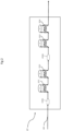
- FIG. 2 illustrates an embodiment of the CP oil-free dry compressor.
- This is a two-stage compressor.
- the compression stages of the circuit are connected in series. This means that the compressors are located on the same branch of the circuit.
- Increasing the gas pressure reduces the power required to liquefy the mixture and improves the efficiency of the process.
- compression is carried out in two stages. This improves the compression efficiency by cooling the gas at the outlet of each stage.
- the compressor is also protected from possible overheating.
- Gas from exchanger E103 shown in figure 1 enters the CP compressor via line 220.
- the gas is fed to the CP201 compressor.
- the thermal energy generated by the compression is recovered by the E211 exchanger, then the E212 exchanger.
- the gas is brought to the CP202 compressor.
- the thermal energy generated by the compression is recovered by the E213 exchanger, then the E214 exchanger.
- the exchangers E211 and E213 use water as a heat transfer fluid. This water heated by the exchangers can be used to heat structures located near the device according to the invention.
- the exchangers E212 and E214 use air as a heat transfer fluid.
- the exchangers E211 and E212 and independently the exchangers E213 and E214 allow a reduction in the temperature of the gas.
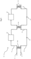
- FIG 3 illustrates an embodiment of a cooling device.
- the device for producing liquid carbon dioxide according to the invention comprises two liquefiers E105 and E106 illustrated in the figure 1 .
- FIG 3 illustrates a cooling device CR that can be connected to the liquefiers E105 and E106.
- This cooling device is connected to a liquefier E301 at the inlet, from which a non-liquefied gas 31 is introduced and at the outlet from which a liquefied gas 32 is extracted.
- the liquefier E301 has an outlet 35 and an inlet 36. The outlet 35 and inlet 36 are intended to be fluidically connected to the cooling device CR.
- the cooling device CR comprises a series of two independent cooling circuits positioned in cascade, here comprising a low-temperature cooling circuit 33 and a high-temperature cooling circuit 34.
- the basic principle of the cooling device is that the low-temperature cooling circuit 33 extracts the calories from the liquefier E301 by being fluidically connected to the outlet 35 and inlet 36 of the liquefier E301.
- the high-temperature cooling circuit 34 extracts the calories from the low-temperature cooling circuit 33.
- the two high-temperature 34 and low-temperature 33 cooling circuits are independent and are in parallel with each other, while being in cascade.
- the high-temperature cooling circuit 34 comprises, in the direction of circulation of a first refrigerant fluid illustrated by the arrows in the figure, an associated compressor 311, a condenser 312, here in the form of a heat exchanger, which makes it possible to extract the calories from the high-temperature cooling circuit 34 to the outside of the cooling device. Downstream of the condenser 312, the high-temperature cooling circuit 34 comprises an expansion valve 313.
- the low-temperature cooling circuit 33 comprises, still in the direction of circulation of a second refrigerant fluid, which is associated with it, illustrated by the arrows in the figure, an associated compressor 321 followed by a condenser 322 followed by an expansion valve 323.
- the condenser 322 is here a heat exchanger, the second part of which forms an evaporator for the high-temperature cooling circuit 34 in which it is integrated downstream of the expansion valve 313 and upstream of the compressor 311 of the high-temperature cooling circuit 34.
- the condenser/evaporator 322 forms, here in this embodiment of the cooling device CR, means for extracting calories thermally connecting the low-temperature cooling circuit 33 to the high-temperature cooling circuit 34.
- the low-temperature cooling circuit 33 comprises, downstream of the expansion valve 323, an outlet pipe fluidly connected to the inlet 36 of the liquefier E301. Similarly, the low-temperature cooling circuit 33 comprises an inlet pipe upstream of the compressor 321 which is fluidly connected to the outlet 35 of the liquefier E301.
- the low-temperature cooling circuit 33 and the high-temperature cooling circuit 34 may comprise separators downstream of the compressors so as to separate the oil extracted from the compressor. A recycling loop for this oil to the compressor is conceivable.
- the liquefaction device 1 according to the invention is included in a container.
- a container is a box of standardized dimensions that can be used for handling, storing or transporting materials or batches of objects for which it makes it possible to simplify the packaging.
- the container in which the liquefaction device is arranged can be a maritime transport container such as standardized in ISO 668:2020 and ISO 1496-3.
- the liquefaction device is easily transportable and can be installed close to the gas production unit to be liquefied.
- a gas from a biogas purification unit produced by a methanizer of the following composition is treated by the process according to the invention: Table 1 CO2 91.7% CH 4 8% O 2 0.15% N 2 0.15%
- the carbon dioxide produced complies with the European Pharmacopoeia, EN936/EIGA/ISBT and Regulation RE 231/2012CE.
- the process according to the invention consumes from 0.18kW/h to 0.27kW/h per kg of liquid CO2 produced, depending on the composition of the gas treated.
Landscapes
- Engineering & Computer Science (AREA)
- Chemical & Material Sciences (AREA)
- Chemical Kinetics & Catalysis (AREA)
- Thermal Sciences (AREA)
- Physics & Mathematics (AREA)
- General Engineering & Computer Science (AREA)
- Mechanical Engineering (AREA)
- General Chemical & Material Sciences (AREA)
- Oil, Petroleum & Natural Gas (AREA)
- Analytical Chemistry (AREA)
- Organic Chemistry (AREA)
- Inorganic Chemistry (AREA)
- Carbon And Carbon Compounds (AREA)
- Separation By Low-Temperature Treatments (AREA)
Priority Applications (12)
| Application Number | Priority Date | Filing Date | Title |
|---|---|---|---|
| PT231692252T PT4450144T (pt) | 2023-04-21 | 2023-04-21 | Método para liquefazer dióxido de carbono |
| ES23169225T ES3058725T3 (en) | 2023-04-21 | 2023-04-21 | Method for liquefying carbon dioxide |
| EP23169225.2A EP4450144B1 (de) | 2023-04-21 | 2023-04-21 | Verfahren zur verflüssigung von kohlendioxid |
| PL23169225.2T PL4450144T3 (pl) | 2023-04-21 | 2023-04-21 | Sposób skraplania dwutlenku węgla |
| DK23169225.2T DK4450144T3 (da) | 2023-04-21 | 2023-04-21 | Fremgangsmåde til flydendegørelse af carbondioxid |
| FIEP23169225.2T FI4450144T3 (fi) | 2023-04-21 | 2023-04-21 | Menetelmä hiilidioksidin nesteyttämiseksi |
| AU2024257034A AU2024257034A1 (en) | 2023-04-21 | 2024-03-29 | Method for liquefying carbon dioxide |
| PCT/EP2024/058740 WO2024217852A1 (fr) | 2023-04-21 | 2024-03-29 | Procede de liquefaction de dioxyde de carbone |
| CN202480026837.5A CN121712577A (zh) | 2023-04-21 | 2024-03-29 | 用于液化二氧化碳的方法 |
| KR1020257039196A KR20260007592A (ko) | 2023-04-21 | 2024-03-29 | 이산화탄소 액화 방법 |
| JP2025561366A JP2026512539A (ja) | 2023-04-21 | 2024-03-29 | 二酸化炭素の液化方法 |
| MX2025012546A MX2025012546A (es) | 2023-04-21 | 2025-10-21 | Metodo para licuar dioxido de carbono |
Applications Claiming Priority (1)
| Application Number | Priority Date | Filing Date | Title |
|---|---|---|---|
| EP23169225.2A EP4450144B1 (de) | 2023-04-21 | 2023-04-21 | Verfahren zur verflüssigung von kohlendioxid |
Publications (2)
| Publication Number | Publication Date |
|---|---|
| EP4450144A1 true EP4450144A1 (de) | 2024-10-23 |
| EP4450144B1 EP4450144B1 (de) | 2025-10-15 |
Family
ID=86142665
Family Applications (1)
| Application Number | Title | Priority Date | Filing Date |
|---|---|---|---|
| EP23169225.2A Active EP4450144B1 (de) | 2023-04-21 | 2023-04-21 | Verfahren zur verflüssigung von kohlendioxid |
Country Status (12)
| Country | Link |
|---|---|
| EP (1) | EP4450144B1 (de) |
| JP (1) | JP2026512539A (de) |
| KR (1) | KR20260007592A (de) |
| CN (1) | CN121712577A (de) |
| AU (1) | AU2024257034A1 (de) |
| DK (1) | DK4450144T3 (de) |
| ES (1) | ES3058725T3 (de) |
| FI (1) | FI4450144T3 (de) |
| MX (1) | MX2025012546A (de) |
| PL (1) | PL4450144T3 (de) |
| PT (1) | PT4450144T (de) |
| WO (1) | WO2024217852A1 (de) |
Citations (3)
| Publication number | Priority date | Publication date | Assignee | Title |
|---|---|---|---|---|
| US20070231244A1 (en) * | 2006-04-03 | 2007-10-04 | Shah Minish M | Carbon dioxide purification method |
| US20120137728A1 (en) * | 2010-04-16 | 2012-06-07 | Kourosh Zanganeh | Auto-refrigerated gas separation system for carbon dioxide capture and compression |
| CN107300294A (zh) * | 2017-08-04 | 2017-10-27 | 中国华能集团清洁能源技术研究院有限公司 | 一种烟气碳捕集系统的二氧化碳液化装置及方法 |
-
2023
- 2023-04-21 ES ES23169225T patent/ES3058725T3/es active Active
- 2023-04-21 DK DK23169225.2T patent/DK4450144T3/da active
- 2023-04-21 FI FIEP23169225.2T patent/FI4450144T3/fi active
- 2023-04-21 PL PL23169225.2T patent/PL4450144T3/pl unknown
- 2023-04-21 EP EP23169225.2A patent/EP4450144B1/de active Active
- 2023-04-21 PT PT231692252T patent/PT4450144T/pt unknown
-
2024
- 2024-03-29 CN CN202480026837.5A patent/CN121712577A/zh active Pending
- 2024-03-29 KR KR1020257039196A patent/KR20260007592A/ko active Pending
- 2024-03-29 WO PCT/EP2024/058740 patent/WO2024217852A1/fr not_active Ceased
- 2024-03-29 JP JP2025561366A patent/JP2026512539A/ja active Pending
- 2024-03-29 AU AU2024257034A patent/AU2024257034A1/en active Pending
-
2025
- 2025-10-21 MX MX2025012546A patent/MX2025012546A/es unknown
Patent Citations (3)
| Publication number | Priority date | Publication date | Assignee | Title |
|---|---|---|---|---|
| US20070231244A1 (en) * | 2006-04-03 | 2007-10-04 | Shah Minish M | Carbon dioxide purification method |
| US20120137728A1 (en) * | 2010-04-16 | 2012-06-07 | Kourosh Zanganeh | Auto-refrigerated gas separation system for carbon dioxide capture and compression |
| CN107300294A (zh) * | 2017-08-04 | 2017-10-27 | 中国华能集团清洁能源技术研究院有限公司 | 一种烟气碳捕集系统的二氧化碳液化装置及方法 |
Also Published As
| Publication number | Publication date |
|---|---|
| EP4450144B1 (de) | 2025-10-15 |
| KR20260007592A (ko) | 2026-01-14 |
| PL4450144T3 (pl) | 2026-04-13 |
| JP2026512539A (ja) | 2026-04-16 |
| AU2024257034A1 (en) | 2025-10-30 |
| ES3058725T3 (en) | 2026-03-12 |
| DK4450144T3 (da) | 2026-01-19 |
| CN121712577A (zh) | 2026-03-20 |
| MX2025012546A (es) | 2026-02-03 |
| PT4450144T (pt) | 2026-01-15 |
| WO2024217852A1 (fr) | 2024-10-24 |
| FI4450144T3 (fi) | 2026-01-12 |
Similar Documents
| Publication | Publication Date | Title |
|---|---|---|
| EP1869385B1 (de) | Integriertes verfahren und integrierte anlage für die kryogene adsorption und trennung zur herstellung von co2 | |
| CA3024382C (fr) | Procede de separation cryogenique d'un debit d'alimentation contenant du methane et des gaz de l'air, installation pour la production de bio methane par epuration de biogaz issus d'installations de stockage de dechets non-dangereux (isdnd) mettant en oeuvre le procede | |
| AU745739B2 (en) | Autorefrigeration separation of carbon dioxide | |
| FR3075659B1 (fr) | Procede de production d'un courant de gaz naturel a partir d'un courant de biogaz. | |
| FR3052684A1 (fr) | Appareil et procede de separation de co2 a basse temperature comprenant une etape de separation par permeation | |
| EP2379968A1 (de) | Kohlendioxidgewinnungsverfahren unter verwendung von kryokondensation | |
| EP3727648B1 (de) | Verfahren zum destillieren eines sauerstoffhaltigen gasstroms | |
| EP4149654B1 (de) | Anlage und verfahren zur herstellung von biomethan mit begrenztem methanverlust und begrenzten co2-emissionen | |
| EP4450144B1 (de) | Verfahren zur verflüssigung von kohlendioxid | |
| WO2026013157A2 (fr) | Procédé de purification de dioxyde de carbone liquéfié à partir de gaz liquéfié collecté | |
| EP4101911B1 (de) | Kryogene reinigung von biogas mit vorabscheidung und externer verfestigung von kohlendioxid | |
| FR3116445A1 (fr) | Procédé de séparation cryogénique d'un débit d'alimentation à base de biométhane, procédé de production de biométhane intégrant ladite séparation cryogénique et installation associée. | |
| FR3157221A1 (fr) | Installation et procédé de production de biométhane gazeux et de CO2 liquide | |
| FR3164774A1 (fr) | Procédé de liquéfaction et de purification à haute pression de dioxyde de carbone | |
| FR3151978A1 (fr) | Dispositif de piégeage de dioxyde de carbone par carbonatation | |
| FR3141997A1 (fr) | Procédé et appareil de distillation cryogénique pour production de CO2 liquide | |
| WO2019122662A1 (fr) | Procédé de limitation de la concentration d'oxygène contenu dans un courant de biométhane |
Legal Events
| Date | Code | Title | Description |
|---|---|---|---|
| PUAI | Public reference made under article 153(3) epc to a published international application that has entered the european phase |
Free format text: ORIGINAL CODE: 0009012 |
|
| STAA | Information on the status of an ep patent application or granted ep patent |
Free format text: STATUS: THE APPLICATION HAS BEEN PUBLISHED |
|
| AK | Designated contracting states |
Kind code of ref document: A1 Designated state(s): AL AT BE BG CH CY CZ DE DK EE ES FI FR GB GR HR HU IE IS IT LI LT LU LV MC ME MK MT NL NO PL PT RO RS SE SI SK SM TR |
|
| STAA | Information on the status of an ep patent application or granted ep patent |
Free format text: STATUS: REQUEST FOR EXAMINATION WAS MADE |
|
| 17P | Request for examination filed |
Effective date: 20250131 |
|
| RIC1 | Information provided on ipc code assigned before grant |
Ipc: F25J 3/02 20060101ALN20250318BHEP Ipc: B01D 53/26 20060101ALI20250318BHEP Ipc: F25J 1/00 20060101ALI20250318BHEP Ipc: F25J 3/06 20060101ALI20250318BHEP Ipc: C01B 32/50 20170101ALI20250318BHEP Ipc: B01D 53/22 20060101ALI20250318BHEP Ipc: B01D 53/00 20060101AFI20250318BHEP |
|
| GRAP | Despatch of communication of intention to grant a patent |
Free format text: ORIGINAL CODE: EPIDOSNIGR1 |
|
| RIC1 | Information provided on ipc code assigned before grant |
Ipc: F25J 3/02 20060101ALN20250331BHEP Ipc: B01D 53/26 20060101ALI20250331BHEP Ipc: F25J 1/00 20060101ALI20250331BHEP Ipc: F25J 3/06 20060101ALI20250331BHEP Ipc: C01B 32/50 20170101ALI20250331BHEP Ipc: B01D 53/22 20060101ALI20250331BHEP Ipc: B01D 53/00 20060101AFI20250331BHEP |
|
| STAA | Information on the status of an ep patent application or granted ep patent |
Free format text: STATUS: GRANT OF PATENT IS INTENDED |
|
| INTG | Intention to grant announced |
Effective date: 20250507 |
|
| GRAS | Grant fee paid |
Free format text: ORIGINAL CODE: EPIDOSNIGR3 |
|
| GRAA | (expected) grant |
Free format text: ORIGINAL CODE: 0009210 |
|
| STAA | Information on the status of an ep patent application or granted ep patent |
Free format text: STATUS: THE PATENT HAS BEEN GRANTED |
|
| AK | Designated contracting states |
Kind code of ref document: B1 Designated state(s): AL AT BE BG CH CY CZ DE DK EE ES FI FR GB GR HR HU IE IS IT LI LT LU LV MC ME MK MT NL NO PL PT RO RS SE SI SK SM TR |
|
| REG | Reference to a national code |
Ref country code: GB Ref legal event code: FG4D Free format text: NOT ENGLISH Ref country code: CH Ref legal event code: F10 Free format text: ST27 STATUS EVENT CODE: U-0-0-F10-F00 (AS PROVIDED BY THE NATIONAL OFFICE) Effective date: 20251015 |
|
| REG | Reference to a national code |
Ref country code: IE Ref legal event code: FG4D Free format text: LANGUAGE OF EP DOCUMENT: FRENCH |
|
| REG | Reference to a national code |
Ref country code: DE Ref legal event code: R096 Ref document number: 602023007442 Country of ref document: DE |
|
| REG | Reference to a national code |
Ref country code: FI Ref legal event code: FGE |
|
| REG | Reference to a national code |
Ref country code: PT Ref legal event code: SC4A Ref document number: 4450144 Country of ref document: PT Date of ref document: 20260115 Kind code of ref document: T Free format text: AVAILABILITY OF NATIONAL TRANSLATION Effective date: 20260109 |
|
| REG | Reference to a national code |
Ref country code: DK Ref legal event code: T3 Effective date: 20260114 |
|
| REG | Reference to a national code |
Ref country code: SE Ref legal event code: TRGR |
|
| REG | Reference to a national code |
Ref country code: NL Ref legal event code: FP |
|
| REG | Reference to a national code |
Ref country code: CH Ref legal event code: R17 Free format text: ST27 STATUS EVENT CODE: U-0-0-R10-R17 (AS PROVIDED BY THE NATIONAL OFFICE) Effective date: 20260129 |
|
| REG | Reference to a national code |
Ref country code: ES Ref legal event code: FG2A Ref document number: 3058725 Country of ref document: ES Kind code of ref document: T3 Effective date: 20260312 |
|
| REG | Reference to a national code |
Ref country code: AT Ref legal event code: MK05 Ref document number: 1846493 Country of ref document: AT Kind code of ref document: T Effective date: 20251015 |
|
| REG | Reference to a national code |
Ref country code: LT Ref legal event code: MG9D |
|
| PG25 | Lapsed in a contracting state [announced via postgrant information from national office to epo] |
Ref country code: HR Free format text: LAPSE BECAUSE OF FAILURE TO SUBMIT A TRANSLATION OF THE DESCRIPTION OR TO PAY THE FEE WITHIN THE PRESCRIBED TIME-LIMIT Effective date: 20251015 Ref country code: AT Free format text: LAPSE BECAUSE OF FAILURE TO SUBMIT A TRANSLATION OF THE DESCRIPTION OR TO PAY THE FEE WITHIN THE PRESCRIBED TIME-LIMIT Effective date: 20251015 |
|
| PG25 | Lapsed in a contracting state [announced via postgrant information from national office to epo] |
Ref country code: RS Free format text: LAPSE BECAUSE OF FAILURE TO SUBMIT A TRANSLATION OF THE DESCRIPTION OR TO PAY THE FEE WITHIN THE PRESCRIBED TIME-LIMIT Effective date: 20260115 |
|
| PG25 | Lapsed in a contracting state [announced via postgrant information from national office to epo] |
Ref country code: IS Free format text: LAPSE BECAUSE OF FAILURE TO SUBMIT A TRANSLATION OF THE DESCRIPTION OR TO PAY THE FEE WITHIN THE PRESCRIBED TIME-LIMIT Effective date: 20260215 |