EP4450044A1 - Elektrischer ofen - Google Patents
Elektrischer ofen Download PDFInfo
- Publication number
- EP4450044A1 EP4450044A1 EP23807990.9A EP23807990A EP4450044A1 EP 4450044 A1 EP4450044 A1 EP 4450044A1 EP 23807990 A EP23807990 A EP 23807990A EP 4450044 A1 EP4450044 A1 EP 4450044A1
- Authority
- EP
- European Patent Office
- Prior art keywords
- heater
- convector
- closed
- steam
- electric stove
- Prior art date
- Legal status (The legal status is an assumption and is not a legal conclusion. Google has not performed a legal analysis and makes no representation as to the accuracy of the status listed.)
- Withdrawn
Links
Images



Classifications
-
- A—HUMAN NECESSITIES
- A61—MEDICAL OR VETERINARY SCIENCE; HYGIENE
- A61H—PHYSICAL THERAPY APPARATUS, e.g. DEVICES FOR LOCATING OR STIMULATING REFLEX POINTS IN THE BODY; ARTIFICIAL RESPIRATION; MASSAGE; BATHING DEVICES FOR SPECIAL THERAPEUTIC OR HYGIENIC PURPOSES OR SPECIFIC PARTS OF THE BODY
- A61H33/00—Bathing devices for special therapeutic or hygienic purposes
- A61H33/06—Artificial hot-air or cold-air baths; Steam or gas baths or douches, e.g. sauna or Finnish baths
- A61H33/063—Heaters specifically designed therefor
-
- A—HUMAN NECESSITIES
- A61—MEDICAL OR VETERINARY SCIENCE; HYGIENE
- A61H—PHYSICAL THERAPY APPARATUS, e.g. DEVICES FOR LOCATING OR STIMULATING REFLEX POINTS IN THE BODY; ARTIFICIAL RESPIRATION; MASSAGE; BATHING DEVICES FOR SPECIAL THERAPEUTIC OR HYGIENIC PURPOSES OR SPECIFIC PARTS OF THE BODY
- A61H33/00—Bathing devices for special therapeutic or hygienic purposes
- A61H33/06—Artificial hot-air or cold-air baths; Steam or gas baths or douches, e.g. sauna or Finnish baths
-
- A—HUMAN NECESSITIES
- A61—MEDICAL OR VETERINARY SCIENCE; HYGIENE
- A61H—PHYSICAL THERAPY APPARATUS, e.g. DEVICES FOR LOCATING OR STIMULATING REFLEX POINTS IN THE BODY; ARTIFICIAL RESPIRATION; MASSAGE; BATHING DEVICES FOR SPECIAL THERAPEUTIC OR HYGIENIC PURPOSES OR SPECIFIC PARTS OF THE BODY
- A61H33/00—Bathing devices for special therapeutic or hygienic purposes
- A61H33/005—Electrical circuits therefor
-
- A—HUMAN NECESSITIES
- A61—MEDICAL OR VETERINARY SCIENCE; HYGIENE
- A61H—PHYSICAL THERAPY APPARATUS, e.g. DEVICES FOR LOCATING OR STIMULATING REFLEX POINTS IN THE BODY; ARTIFICIAL RESPIRATION; MASSAGE; BATHING DEVICES FOR SPECIAL THERAPEUTIC OR HYGIENIC PURPOSES OR SPECIFIC PARTS OF THE BODY
- A61H33/00—Bathing devices for special therapeutic or hygienic purposes
- A61H33/06—Artificial hot-air or cold-air baths; Steam or gas baths or douches, e.g. sauna or Finnish baths
- A61H33/063—Heaters specifically designed therefor
- A61H33/065—Heaters specifically designed therefor with steam generators
-
- A—HUMAN NECESSITIES
- A61—MEDICAL OR VETERINARY SCIENCE; HYGIENE
- A61H—PHYSICAL THERAPY APPARATUS, e.g. DEVICES FOR LOCATING OR STIMULATING REFLEX POINTS IN THE BODY; ARTIFICIAL RESPIRATION; MASSAGE; BATHING DEVICES FOR SPECIAL THERAPEUTIC OR HYGIENIC PURPOSES OR SPECIFIC PARTS OF THE BODY
- A61H33/00—Bathing devices for special therapeutic or hygienic purposes
- A61H33/06—Artificial hot-air or cold-air baths; Steam or gas baths or douches, e.g. sauna or Finnish baths
- A61H33/066—Cabins therefor
-
- A—HUMAN NECESSITIES
- A61—MEDICAL OR VETERINARY SCIENCE; HYGIENE
- A61H—PHYSICAL THERAPY APPARATUS, e.g. DEVICES FOR LOCATING OR STIMULATING REFLEX POINTS IN THE BODY; ARTIFICIAL RESPIRATION; MASSAGE; BATHING DEVICES FOR SPECIAL THERAPEUTIC OR HYGIENIC PURPOSES OR SPECIFIC PARTS OF THE BODY
- A61H33/00—Bathing devices for special therapeutic or hygienic purposes
- A61H33/60—Components specifically designed for the therapeutic baths of groups A61H33/00
- A61H33/6005—Special constructive structural details of the bathtub, e.g. of the walls or supporting structure
-
- F—MECHANICAL ENGINEERING; LIGHTING; HEATING; WEAPONS; BLASTING
- F24—HEATING; RANGES; VENTILATING
- F24C—DOMESTIC STOVES OR RANGES ; DETAILS OF DOMESTIC STOVES OR RANGES, OF GENERAL APPLICATION
- F24C7/00—Stoves or ranges heated by electric energy
-
- F—MECHANICAL ENGINEERING; LIGHTING; HEATING; WEAPONS; BLASTING
- F24—HEATING; RANGES; VENTILATING
- F24H—FLUID HEATERS, e.g. WATER OR AIR HEATERS, HAVING HEAT-GENERATING MEANS, e.g. HEAT PUMPS, IN GENERAL
- F24H3/00—Air heaters
- F24H3/002—Air heaters using electric energy supply
-
- H—ELECTRICITY
- H05—ELECTRIC TECHNIQUES NOT OTHERWISE PROVIDED FOR
- H05B—ELECTRIC HEATING; ELECTRIC LIGHT SOURCES NOT OTHERWISE PROVIDED FOR; CIRCUIT ARRANGEMENTS FOR ELECTRIC LIGHT SOURCES, IN GENERAL
- H05B3/00—Ohmic-resistance heating
- H05B3/40—Heating elements having the shape of rods or tubes
- H05B3/42—Heating elements having the shape of rods or tubes non-flexible
- H05B3/48—Heating elements having the shape of rods or tubes non-flexible heating conductor embedded in insulating material
-
- A—HUMAN NECESSITIES
- A61—MEDICAL OR VETERINARY SCIENCE; HYGIENE
- A61H—PHYSICAL THERAPY APPARATUS, e.g. DEVICES FOR LOCATING OR STIMULATING REFLEX POINTS IN THE BODY; ARTIFICIAL RESPIRATION; MASSAGE; BATHING DEVICES FOR SPECIAL THERAPEUTIC OR HYGIENIC PURPOSES OR SPECIFIC PARTS OF THE BODY
- A61H33/00—Bathing devices for special therapeutic or hygienic purposes
- A61H33/06—Artificial hot-air or cold-air baths; Steam or gas baths or douches, e.g. sauna or Finnish baths
- A61H2033/061—Artificial hot-air baths
-
- A—HUMAN NECESSITIES
- A61—MEDICAL OR VETERINARY SCIENCE; HYGIENE
- A61H—PHYSICAL THERAPY APPARATUS, e.g. DEVICES FOR LOCATING OR STIMULATING REFLEX POINTS IN THE BODY; ARTIFICIAL RESPIRATION; MASSAGE; BATHING DEVICES FOR SPECIAL THERAPEUTIC OR HYGIENIC PURPOSES OR SPECIFIC PARTS OF THE BODY
- A61H33/00—Bathing devices for special therapeutic or hygienic purposes
- A61H33/06—Artificial hot-air or cold-air baths; Steam or gas baths or douches, e.g. sauna or Finnish baths
- A61H2033/062—Artificial cold-air baths
-
- A—HUMAN NECESSITIES
- A61—MEDICAL OR VETERINARY SCIENCE; HYGIENE
- A61H—PHYSICAL THERAPY APPARATUS, e.g. DEVICES FOR LOCATING OR STIMULATING REFLEX POINTS IN THE BODY; ARTIFICIAL RESPIRATION; MASSAGE; BATHING DEVICES FOR SPECIAL THERAPEUTIC OR HYGIENIC PURPOSES OR SPECIFIC PARTS OF THE BODY
- A61H33/00—Bathing devices for special therapeutic or hygienic purposes
- A61H33/06—Artificial hot-air or cold-air baths; Steam or gas baths or douches, e.g. sauna or Finnish baths
- A61H2033/068—Steam baths
-
- A—HUMAN NECESSITIES
- A61—MEDICAL OR VETERINARY SCIENCE; HYGIENE
- A61H—PHYSICAL THERAPY APPARATUS, e.g. DEVICES FOR LOCATING OR STIMULATING REFLEX POINTS IN THE BODY; ARTIFICIAL RESPIRATION; MASSAGE; BATHING DEVICES FOR SPECIAL THERAPEUTIC OR HYGIENIC PURPOSES OR SPECIFIC PARTS OF THE BODY
- A61H2201/00—Characteristics of apparatus not provided for in the preceding codes
- A61H2201/02—Characteristics of apparatus not provided for in the preceding codes heated or cooled
- A61H2201/0221—Mechanism for heating or cooling
-
- A—HUMAN NECESSITIES
- A61—MEDICAL OR VETERINARY SCIENCE; HYGIENE
- A61H—PHYSICAL THERAPY APPARATUS, e.g. DEVICES FOR LOCATING OR STIMULATING REFLEX POINTS IN THE BODY; ARTIFICIAL RESPIRATION; MASSAGE; BATHING DEVICES FOR SPECIAL THERAPEUTIC OR HYGIENIC PURPOSES OR SPECIFIC PARTS OF THE BODY
- A61H2201/00—Characteristics of apparatus not provided for in the preceding codes
- A61H2201/02—Characteristics of apparatus not provided for in the preceding codes heated or cooled
- A61H2201/0221—Mechanism for heating or cooling
- A61H2201/0228—Mechanism for heating or cooling heated by an electric resistance element
-
- A—HUMAN NECESSITIES
- A61—MEDICAL OR VETERINARY SCIENCE; HYGIENE
- A61H—PHYSICAL THERAPY APPARATUS, e.g. DEVICES FOR LOCATING OR STIMULATING REFLEX POINTS IN THE BODY; ARTIFICIAL RESPIRATION; MASSAGE; BATHING DEVICES FOR SPECIAL THERAPEUTIC OR HYGIENIC PURPOSES OR SPECIFIC PARTS OF THE BODY
- A61H2201/00—Characteristics of apparatus not provided for in the preceding codes
- A61H2201/50—Control means thereof
- A61H2201/5058—Sensors or detectors
- A61H2201/5082—Temperature sensors
-
- F—MECHANICAL ENGINEERING; LIGHTING; HEATING; WEAPONS; BLASTING
- F24—HEATING; RANGES; VENTILATING
- F24H—FLUID HEATERS, e.g. WATER OR AIR HEATERS, HAVING HEAT-GENERATING MEANS, e.g. HEAT PUMPS, IN GENERAL
- F24H2250/00—Electrical heat generating means
- F24H2250/02—Resistances
Definitions
- the present device relates to an electrical engineering product, particularly, to an electrical heating device structure that is intended to provide heating and steam generation, and therefore can be used for outfitting a bath or a sauna.
- the bottom part of an electric heating device has a terminal block to connect to a control panel.
- Crushed stone gabbro-diabase, soapstone or quartzite
- Heat storage capacity of said electric heating devices is ensured by said devices having an open stone heater and a closed stone heater.
- a closed stone heater incorporates a cup with a heat storage bank. Due to its minor volume, the closed stone heater ensures quick heat-up of heat storage elements, and quick cooling when in steam generation mode.
- An additional amount of steam is to be obtained from stones in the open stone heater.
- Ensuring the required steam generation mode entails a decrease in a steam room temperature due to decreasing temperature of the heat storage elements during steam generation.
- the process of steam generation and maintaining the temperature in a steam room is of a discontinuous nature, which leads to lower steam quality or to decreasing the temperature in a steam room, which will, again, impact the quality of steam generation.
- a heat-insulated enclosure of the stove has an inbuilt ventilation air supply channel that has a fan with a check valve enabling air supply through air gaps between the heat storage elements; said fan with the check valve, said temperature sensor of heat storage elements and said electric heater can be connected to a control unit. Due to the fan conducting blowoff of the heat storage elements and electric heaters, hot air is supplied to a steam room as the electric heaters cool down simultaneously, while the temperature of the heat storage elements decreases. To obtain steam directly from the heat storage elements, said storage elements require additional heat-up, and therefore more time is needed to heat-up the steam room and the heat storage elements. The process of steam generation and maintaining the temperature in the steam room is of a discontinuous nature.
- An air channel that is connected to the fan discharge outlet has an outlet hole adjacent to which there is an adjustment detail implemented as damper plate and connected to the control unit.
- a steam generator is a vessel, standalone from the main device, with a steam outlet, an inlet pipeline for continuous supply of water that is evaporated by tubular electric heaters (TEH), where water level is set by a float valve in a separate vessel with a non-leak-tight cover that is connected to a water pipeline system via a nozzle.
- TSH tubular electric heaters
- the air temperature inside the steam room is regulated by the fan and the damper plate, while the steam generator intended for water steam generation is used only to maintain an optimum ratio of temperature and humidity in the steam room, which does not allow to provide fine mist steam that can be obtained only if the temperature mode is at least 500° C.
- the device structure consists of several component parts with moving and wearing surfaces and additional equipment (float valve, damper plate, fan), which have more frequent failures and require repair and maintenance.
- the evaporator is additionally connected to a steam outlet pipe and a pipe adjacent to the top part of sauna stove.
- the device has a complicated operation algorithm, which does not allow to ensure stable and continuous temperature mode and steam room humidifying mode, however, the evaporator design does not allow to provide fine mist steam.
- a furnace casing comprises a foundation with a screen and an enclosure installed on it coaxially, with the walls forming pass-through channels open from beneath, and with a cover on top that has in its center fastened a flexible water- and vapor-permeable heat-resistant mesh, which is located inside the furnace, with louvered windows on the sides.
- a cover on top that has in its center fastened a flexible water- and vapor-permeable heat-resistant mesh, which is located inside the furnace, with louvered windows on the sides.
- vertical cups made of heat-conducting material in a "LU"-shaped pattern, with electric heaters installed on isolators inside said cups.
- the screen prevents heat diffusion to the sides and gathers the heat flow to let it enter a heat-storing chamber as a convection flow.
- a loading chamber of the device is arranged as a flexible mesh made of heat-resistant material, a leak-tight cup is made of heat-resistant steel with wall thickness of at least 3 mm, said cup being partially protected by louvers.
- the device enables water irrigation only for the cup body, where temperature is 450° C, Infrared emission is transmitted to bodies of the cups, wherefrom it is distributed throughout the inner volume of the furnace. Convection air flow is generated in a furnace cavity, then it passes from the bottom through a channel between the foundation body and the screen body, thus filling the furnace.
- Infrared emission partially heats up the screen and is reflected from said screen back to the furnace center, as it is combined with the other heat flows.
- the temperature of the rising air flow in the furnace center reaches the maximum value.
- a high-temperature air flow, focused in the central area, meets obstacles as it ascends: a chamber, which it bypasses from its side, and through channels within the heat storage load it enters the chamber and heats up the heat storage load uniformly to a high temperature. Having partially transferred its heat, the air heats up the steam room as it exits.
- a less heated flow in the furnace rises at a screen wall that also gets partially heated and transfers its heat into a channel between the screen and the enclosure. Consequently, self-regulating heat convection flows arise in the channels, thus heating up the bath steam room.
- the electric stove automatically shuts down upon reaching a temperature of 125° C in the steam room and remains in shutdown until the temperature decreases down to 110° C, after which said heater turns on, whereupon the cycle repeats.
- the required temperature 380° C
- water is in portions supplied to said heat storage load to obtain steam.
- the process of steam generation to obtain dry steam has a short duration.
- the heat storage load may have not enough time to heat up to an adequately high temperature to obtain dry steam.
- the temperature required for steam generation will be need to be reached, which will entail an excessive rise in the air temperature in the room.
- the process of steam generation and maintaining the temperature in the steam room is of a discontinuous nature.
- Severe infrared radiation in the room may cause burns.
- the device is offered for efficient generation of dry steam in a steam room with a volume of 12 m 3 .
- Exceeding the thresholds of the said parameters impairs the operation efficiency, as the result then implies obtaining raw steam or excessive growth in power capacity of the heaters and, accordingly, an increased hazard.
- said claimed device is a framework structure with a metal enclosure shaped as regular and vertically oriented parallelepiped, where in a cover is installed a bowl of a decorative external stone heater with heat storage elements made of natural stones, and a convection grille through which hot air is supplied to the room.
- Said bowl of an external stone heater is implemented as a vessel with walls oriented at an angle towards the center of the bowl base; a round cross-section nozzle is welded to a hole in the bottom of the bowl.
- a closed stone heater module containing heat storage elements for generation of fine mist steam, and a convector heater located beneath said module.
- a convection channel duct with rectangular cross-section that is adjacent to the rear wall of the device enclosure, protrudes with its upper part under the convection grille of the device cover.
- the device From its outer side, the device has a compound decorative cladding, i. e., tint heat-resistant glass panels or, for example, stone or brick decorative panels, which serves as additional protection from infrared emission generated by said device.
- grinded or crushed natural stones can be used as heat storage elements in an open or closed stone heater.
- the closed stone heater can use artificial heat storage elements, e. g. made of metal slabs of various geometrical shapes, which comply with requirements for temperature drop resistance, heat storage capacity and health protection.
- a closed stone heater module is a metal enclosure shaped as regular vertically oriented parallelepiped with double walls, bottom and cover, between which is placed high-temperature heat insulation material at least 25 mm thick, e. g. ceramic fiber, the physical and chemical properties of which allow to ensure that said structure is lightweight, robust and wear-proof in high-temperature modes of operation, to protect the external room space from infrared emission and not to spend heat on heating-up the steam room itself.
- the closed stone heater cover is in tight contact with the stone heater walls and has a hole through which a nozzle enters from the external stone heater, and to which shaped tubes structures are attached, e. g.
- Said shaped tubes structure may also rest e. g. on mounting brackets fastened to the inner side of the stone heater walls. On the stone heater bottom at least two heating elements are mounted, with a total power capacity of at least 3 kW, and a thermocouple sensor to control the temperature in the closed stone heater.
- the closed stone heater cover has a number of minor horizontal slotted holes with a nozzle over them, out of which the steam, generated by water supplied to heat storage elements of the closed stone heater and passing through the convection channel duct, exits through the convection grille of the said device into the steam room.
- the nozzle is oriented towards the convection channel. Water enters the shaped tubes structur6e of the closed stone heater through the pipe fitting of the external stone heater bowl and then is supplied through the holes in shaped tubes onto the heat storage elements of the closed stone heater.
- Said closed stone heater can accommodate heat storage elements that have a weight between 25 and 30 kg, which will heat up from the heating elements located inside the stone heater to 500° C without heat being spent to warm up the room. Due to a tight connection between the cover and the enclosure of the stone heater, overpressure is generated inside the stone heater, which enhances heat-up of the steam and generation of fine mist steam. With the stones having a temperature of at least 500° C, water is instantly converted into fine mist steam, also known as "light" steam, that allows a person to breath in a free and easy manner in the steam room, and which does not create any water-saturated steam clouds in the same room.
- fine mist steam also known as "light" steam
- a convector heater is a structure shaped as rectangular parallelepiped with two double walls positioned opposite each other, between which is placed heat insulation material, e. g. ceramic fiber at least 25 mm thick, while from the inner side of the walls is placed electrical insulation material, e. g., mica plates, at least 0.5 mm thick;
- the front wall of the convector heater has convection holes arranged as a horizontal grille to let in air into convector from the steam room so that it can be heated, the rear side of the convector heater being open and tightly inserted into a convection channel duct opening through which said air, heated up to the required temperature, is supplied to the steam room through the convection grille.
- a protection screen e. g., an additional steel sheet.
- Inside the convector heater are installed a number of heating spirals, depending on the required capacity of the device and the size of the room to be heated, but not less than 3 kW, that are connected to an electronic control unit through a terminal block fixed on the outside surface of the framework structure. Heating elements and a thermocouple temperature sensor located in the closed stone heater are also connected to the terminal block.
- the control unit is a panel on which a data output unit is located, as well as relay temperature control units.
- the data obtained from the temperature sensor in the closed stone heater and the air temperature in the steam room are sent to the control unit and shown on the display screen; air temperature can be adjusted using the relay, if necessary.
- the design of the device allows to ensure that the steam room is heated without decreasing the steam generation temperature in the closed stone heater and, vice versa, that providing for the required steam generation temperature will not cause a decrease of temperature in the steam room due to ensuring independent high-temperature heating of the heat storage elements of the closed stone heater with simultaneously maintaining the required air temperature in the steam room to obtain fine mist steam.
- the technical result is to produce a device design that ensures continuous high-temperature mode of heating-up the heat storage elements of the closed stone heater, simultaneously maintaining, with the use of a convector, a set required air temperature in the steam room, so that the most desirable mode of steam generation is implemented.
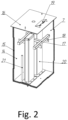
- the device is a framework structure with metal enclosure 1 shaped as rectangular parallelepiped, vertically oriented, fastened to foundation base 2.
- cover 3 On cover 3 are located external stone heater bowl 4 and convection grille 5.
- the walls of metal enclosure 1 are made in such a way that they do not close the area where convector heater 8 is located.
- Convector channel 9, closed by convection grille 5 of cover 3, is fastened on the rear wall of device metal enclosure framework structure 1.
- External stone heater bowl 4 is made as vessel with walls oriented at an angle towards the center of the bowl base, to the bottom of which nozzle 10 is welded. Closed stone heater module 7 and convector heater 8 of the device are connected to electronic control unit 11 through terminal module 12.
- Air sensor 13 for example, can be also connected to electronic control unit, to monitor temperature inside a steam room.
- closed stone heater module 7 is a metal enclosure where side walls and bottom are assembled from double-wall panels 14, between which is placed heat insulation material 15.
- Cover 16 of closed stone heater 7 is insulated from inside with heat insulation material 15.
- Shaped tubes structure 17 with a row of parallel slits or minor holes in the structure horizontal tubes portion oriented downwards is inserted into pipe fitting 10 that is inserted into closed stone heater 7 through opening in cover 16.
- Shaped tubes structure 17 may additionally rest, for example, on mounting brackets 18, which are fastened on the inner side of the walls of closed stone heater module 7.
- cover 16 of closed stone heater 7 has a row of minor oval-shaped slotted holes, horizontally oriented, with nozzle 19 above them that is oriented towards convection channel duct 9, through which the steam enters the steam room through convection grille 5 of cover 3 of the device.
- On the bottom of closed stone heater 7 at least two heating elements 20 are installed, made as spirals of current-conducting materials with a total power capacity of at least 3 kW, in metal boxes with stiffeners at corners and inside the box, filled with electrical insulation, for example, electrical periclases, and thermocouple temperature sensor 21.
- convector heater 8 is a structure of rectangular parallelepiped shape with two side double-walls 22, between which insulation material 23 is placed, while from inner side of the walls is additionally placed electrical insulation material 24; heating elements 25 are fastened to said walls; the front wall of convector heater 8 has convection holes arranged as horizontal grille 26 to let the air go inside convector, while the opposite part of convector heater 8 is open and tightly inserted into an opening in a rear panel of convection channel 9, protruding beyond said panel to a certain extent.
- Heating elements 25 of convector heater 8 are connected to electronic control unit 11 through terminal module 12 that is fastened from outside on framework structure 1.
- Heating elements 25 and thermocouple temperature sensor 21, which are installed in closed stone heater 7, are also connected to terminal module 12.
- Convection channel duct 9 shown on fig.4 consists of rear panel 27 with is minor lateral edges bent at 90° and a rectangular opening in its lower part designed for the size of convector heater 8, with said heater, as shown on fig. 5 , is fastened to the framework structure of said device in such manner that the level of top edge of panel 27 of convection channel 9 is aligned with cover 16 of closed stone heater 7 and panel 28, with is minor lateral edges bent at 90°, that is fastened to panel 27 and is partially covered at its edge by cover 3 of said device, as it is shown on fig.6 .
- the convection channel duct 9 has a bottom formed by bent lower edges of panels 27, 28. Between convection channel duct 9 and framework structure metal casing 1 is placed heat insulation material 29. Protection screen 30 is installed in the bottom portion of inner side of panel 28, opposite to the open portion of convector heater 8.
- Fig.7 shows one of design options for equal distribution of water supplied via pipe fitting 10 to shaped tubes structure 17 onto heat storage elements of closed stone heater 7 through a row of parallel slits or minor holes in the lower portion of the horizontally oriented pipes of the structure.
- the top portion of shaped tubes structure 17 is made from a smaller tube of round section that is welded to the main structure, which enters pipe fitting 10.
- the device operates as follows. Said device is placed in a steam room and connected to electronic control unit 11 via terminal block 12 fastened in the lower side part of framework structure 1.
- Control unit 11 allows to select the automatic modes of the device operation, to control and regulate the temperature in closed stone heater module 7 using thermocouple sensor 21, in the steam room through air sensor 13 connected to control unit 11, to limit the operation time of the device.
- Closed stone heater module 7 and external stone heater bowl 4 is filled with heat storage material and tightly closed with cover 16. Tight contact between cover 16 and closed stone heater module 7 can be additionally ensured, for example, with a heat-resistant cord placed along the inner perimeter of the cover.
- Independent heating of the room is carried out as follows.
- power is supplied from the control unit to spirals made of current conducting materials of heating elements 25 of convector heater 8 by closing the relay control power contacts, said spirals are heated to at least 250° C.
- the ambient air incoming through convection holes in grille 26 into convector heater 8 heats up as it goes through the already heated spirals of heating elements 25, and, being hot enough by that time, is supplied to the steam room through convection channel 9 and holes in convection grille 5.
- the air heating temperature in the convector heater may reach 200° C.
- sensor 13 stops the convector heating.
- water is supplied to external stone heater bowl 4, through a hole in the bowl base water is supplied to the shaped tubes structure through steam pipe 10; then, through holes in the bottom part of horizontally oriented tubes of structure 17, it is equally distributed through heat storage materials of closed stone heater 7 of the device. Due to a tight connection between cover 16 and the casing of closed stone heater 7, excessive pressure is generated inside the stone heater, which contributes to finalizing the heat-up of steam and to generating fine mist steam. As water gets in contact with the heat storage elements of closed stone heater 7, which are enclosed by heated-up internal walls of the closed stone heater, and are heated up to a high temperature, water explodes with a characteristic burst sound.
- Hot steam containing water droplets rises, however in the closed space, as it hits against the hot surface of the internal walls of the closed stone heater, it heats up additionally to an even higher temperature from them and from the air between the heat storage elements, making reoccurring "micro-bursts". Due to a high temperature of that the heat storage elements of closed stone heater 7 are heated to, water particles become even smaller, and therefore, so-called light steam, or fine mist steam, is generated.
- the fine mist steam is discharged with high velocity through nozzle 19 located on cover 16 of closed stone heater 7 and then, through convection channel 9 and holes in convection grille 5 of the device, steam is supplied to the steam room, making a special and characteristic sound that is similar to the "blizzard sound".
- the nozzle in this arrangement is oriented towards the convection channel.
- the design of the device allows if to ensure a continuous high-temperature heating mode for heat storage elements of the closed stone heater, with the convector of the device simultaneously maintaining the required temperature of air in the steam room, which, in its turn, allows to ensure the best steam generation mode possible.
- the quality of steam obtained in the closed stone heater allows a person to breath in a free and easy manner in the steam room, while maintaining the temperature mode for heating up the room and generating steam independently does not allow to make clouds of water-saturated steam in the steam room itself.
Landscapes
- Health & Medical Sciences (AREA)
- Public Health (AREA)
- General Health & Medical Sciences (AREA)
- Physical Education & Sports Medicine (AREA)
- Veterinary Medicine (AREA)
- Animal Behavior & Ethology (AREA)
- Life Sciences & Earth Sciences (AREA)
- Rehabilitation Therapy (AREA)
- Epidemiology (AREA)
- Pain & Pain Management (AREA)
- Engineering & Computer Science (AREA)
- Chemical & Material Sciences (AREA)
- General Engineering & Computer Science (AREA)
- Mechanical Engineering (AREA)
- Combustion & Propulsion (AREA)
- Thermal Sciences (AREA)
- Physics & Mathematics (AREA)
- Devices For Medical Bathing And Washing (AREA)
- Electric Stoves And Ranges (AREA)
- Direct Air Heating By Heater Or Combustion Gas (AREA)
Applications Claiming Priority (2)
| Application Number | Priority Date | Filing Date | Title |
|---|---|---|---|
| RU2022113090A RU2792382C1 (ru) | 2022-05-16 | Печь электрическая | |
| PCT/RU2023/050024 WO2023224515A1 (ru) | 2022-05-16 | 2023-02-10 | Печь электрическая |
Publications (2)
| Publication Number | Publication Date |
|---|---|
| EP4450044A1 true EP4450044A1 (de) | 2024-10-23 |
| EP4450044A8 EP4450044A8 (de) | 2025-11-19 |
Family
ID=88835894
Family Applications (1)
| Application Number | Title | Priority Date | Filing Date |
|---|---|---|---|
| EP23807990.9A Withdrawn EP4450044A1 (de) | 2022-05-16 | 2023-02-10 | Elektrischer ofen |
Country Status (10)
| Country | Link |
|---|---|
| US (1) | US20250161156A1 (de) |
| EP (1) | EP4450044A1 (de) |
| JP (1) | JP2025516730A (de) |
| KR (1) | KR20250006296A (de) |
| CN (1) | CN118748932A (de) |
| CA (1) | CA3253920A1 (de) |
| GB (1) | GB2634660A (de) |
| MD (1) | MD4940B1 (de) |
| RS (1) | RS20241236A1 (de) |
| WO (1) | WO2023224515A1 (de) |
Families Citing this family (1)
| Publication number | Priority date | Publication date | Assignee | Title |
|---|---|---|---|---|
| US20250107964A1 (en) * | 2023-09-28 | 2025-04-03 | High Tech Health International, Inc. | Systems and methods for controlling a sauna |
Family Cites Families (13)
| Publication number | Priority date | Publication date | Assignee | Title |
|---|---|---|---|---|
| JPS5336187Y2 (de) * | 1973-11-27 | 1978-09-04 | ||
| FI83156B (fi) * | 1987-12-31 | 1991-02-28 | Helo Tehtaat Oy | Elektrisk bastuugn. |
| JPH0352991U (de) * | 1989-09-29 | 1991-05-22 | ||
| GB2241051B (en) | 1990-02-19 | 1994-05-18 | Helo Tehtaat Oy | An electric sauna heater |
| RU2057998C1 (ru) | 1993-12-28 | 1996-04-10 | Производственное предприятие "ЭКО-ТЕРМ" | Электропечь для бань |
| JP2010057851A (ja) * | 2008-09-08 | 2010-03-18 | Chubu Suiken:Kk | サウナ装置 |
| KR101060134B1 (ko) * | 2011-03-11 | 2011-08-29 | 여형구 | 방열겸용 사우나스팀발생기 |
| US9283143B2 (en) * | 2011-12-08 | 2016-03-15 | Nikita Krasilnikov | Mobile sauna |
| FI11417U1 (fi) * | 2016-07-07 | 2016-10-17 | Jyrki Hyytiäinen | Löylyveden syöttölaite |
| RU179399U1 (ru) * | 2017-08-21 | 2018-05-14 | Виктор Иванович Вахов | Электрическая печь для сауны Вахова В.И. |
| KR20200000148U (ko) * | 2019-12-31 | 2020-01-20 | (주)극동무공 | 건식 사우나용 석재 테이블 |
| RU2738678C1 (ru) | 2020-05-13 | 2020-12-15 | Виктор Валентинович Маслов | Электрическая печь для русской бани и способ поддержания температуры воздуха электрической печью в парном помещении бани |
| RU2756610C1 (ru) | 2020-12-16 | 2021-10-04 | Вячеслав Геннадьевич Гребенкин | Электрическая печь для парного помещения бани |
-
2023
- 2023-02-10 MD MDA20240036A patent/MD4940B1/ro unknown
- 2023-02-10 WO PCT/RU2023/050024 patent/WO2023224515A1/ru not_active Ceased
- 2023-02-10 JP JP2024568062A patent/JP2025516730A/ja active Pending
- 2023-02-10 GB GB2418359.2A patent/GB2634660A/en active Pending
- 2023-02-10 RS RS20241236A patent/RS20241236A1/sr unknown
- 2023-02-10 KR KR1020247040473A patent/KR20250006296A/ko active Pending
- 2023-02-10 CN CN202380016517.7A patent/CN118748932A/zh active Pending
- 2023-02-10 EP EP23807990.9A patent/EP4450044A1/de not_active Withdrawn
- 2023-02-10 US US18/875,176 patent/US20250161156A1/en active Pending
- 2023-02-10 CA CA3253920A patent/CA3253920A1/en active Pending
Also Published As
| Publication number | Publication date |
|---|---|
| JP2025516730A (ja) | 2025-05-30 |
| MD20240036A2 (ro) | 2025-03-31 |
| CA3253920A1 (en) | 2025-03-03 |
| EP4450044A8 (de) | 2025-11-19 |
| KR20250006296A (ko) | 2025-01-10 |
| GB2634660A (en) | 2025-04-16 |
| GB202418359D0 (en) | 2025-01-29 |
| CN118748932A (zh) | 2024-10-08 |
| RS20241236A1 (sr) | 2025-01-31 |
| US20250161156A1 (en) | 2025-05-22 |
| WO2023224515A1 (ru) | 2023-11-23 |
| MD4940B1 (ro) | 2025-10-31 |
Similar Documents
| Publication | Publication Date | Title |
|---|---|---|
| JPH0236866B2 (de) | ||
| RU2738678C1 (ru) | Электрическая печь для русской бани и способ поддержания температуры воздуха электрической печью в парном помещении бани | |
| RU2756610C1 (ru) | Электрическая печь для парного помещения бани | |
| KR101833594B1 (ko) | 냉온풍가습장치의 그룹 제어 방법 | |
| US20250161156A1 (en) | Electric stove | |
| US6860261B2 (en) | Baking oven construction | |
| EP3167865B1 (de) | Vorrichtung zum einstellen des saunainnenraumklimas und einstellungsverfahren | |
| RU2792382C1 (ru) | Печь электрическая | |
| US6666172B2 (en) | Energy system | |
| US7904974B2 (en) | Device for active temperature equalization in a sauna room | |
| US1958331A (en) | Gas fired unit heater | |
| US2607877A (en) | Heating system | |
| JP2015094498A (ja) | 室内温調システム | |
| TR2024015650T2 (tr) | Elektri̇kli̇ soba | |
| RU219354U1 (ru) | Модуль закрытой каменки электрический | |
| US2017238A (en) | Space heater | |
| RU2822024C1 (ru) | Печь электрическая | |
| RU220125U1 (ru) | Устройство конвекционное | |
| RU2827089C1 (ru) | Сауна | |
| KR101101311B1 (ko) | 나트륨 진공 발열기를 이용한 원적외선 튜브 히터 시스템 | |
| WO2025116779A1 (ru) | Печь электрическая | |
| US3533396A (en) | Pool water heater | |
| JP2506022B2 (ja) | 暖房加湿装置 | |
| CN107339733A (zh) | 一种墙排式取暖器 | |
| US20030079735A1 (en) | Baking oven construction |
Legal Events
| Date | Code | Title | Description |
|---|---|---|---|
| STAA | Information on the status of an ep patent application or granted ep patent |
Free format text: STATUS: THE INTERNATIONAL PUBLICATION HAS BEEN MADE |
|
| PUAI | Public reference made under article 153(3) epc to a published international application that has entered the european phase |
Free format text: ORIGINAL CODE: 0009012 |
|
| STAA | Information on the status of an ep patent application or granted ep patent |
Free format text: STATUS: REQUEST FOR EXAMINATION WAS MADE |
|
| 17P | Request for examination filed |
Effective date: 20240708 |
|
| AK | Designated contracting states |
Kind code of ref document: A1 Designated state(s): AL AT BE BG CH CY CZ DE DK EE ES FI FR GB GR HR HU IE IS IT LI LT LU LV MC ME MK MT NL NO PL PT RO RS SE SI SK SM TR |
|
| DAV | Request for validation of the european patent (deleted) | ||
| DAX | Request for extension of the european patent (deleted) | ||
| RBV | Designated contracting states (corrected) |
Designated state(s): AL CH GB IS LI MC ME MK NO RS SM TR |
|
| REG | Reference to a national code |
Ref country code: DE Ref legal event code: R108 |
|
| STAA | Information on the status of an ep patent application or granted ep patent |
Free format text: STATUS: THE APPLICATION IS DEEMED TO BE WITHDRAWN |
|
| 18D | Application deemed to be withdrawn |
Effective date: 20250902 |