EP4449958A1 - Multi-position blender - Google Patents
Multi-position blender Download PDFInfo
- Publication number
- EP4449958A1 EP4449958A1 EP24171691.9A EP24171691A EP4449958A1 EP 4449958 A1 EP4449958 A1 EP 4449958A1 EP 24171691 A EP24171691 A EP 24171691A EP 4449958 A1 EP4449958 A1 EP 4449958A1
- Authority
- EP
- European Patent Office
- Prior art keywords
- magnet
- blender
- rod
- carrier
- container
- Prior art date
- Legal status (The legal status is an assumption and is not a legal conclusion. Google has not performed a legal analysis and makes no representation as to the accuracy of the status listed.)
- Pending
Links
Images



Classifications
-
- A—HUMAN NECESSITIES
- A47—FURNITURE; DOMESTIC ARTICLES OR APPLIANCES; COFFEE MILLS; SPICE MILLS; SUCTION CLEANERS IN GENERAL
- A47J—KITCHEN EQUIPMENT; COFFEE MILLS; SPICE MILLS; APPARATUS FOR MAKING BEVERAGES
- A47J43/00—Implements for preparing or holding food, not provided for in other groups of this subclass
- A47J43/04—Machines for domestic use not covered elsewhere, e.g. for grinding, mixing, stirring, kneading, emulsifying, whipping or beating foodstuffs, e.g. power-driven
- A47J43/07—Parts or details, e.g. mixing tools, whipping tools
- A47J43/0716—Parts or details, e.g. mixing tools, whipping tools for machines with tools driven from the lower side
-
- A—HUMAN NECESSITIES
- A47—FURNITURE; DOMESTIC ARTICLES OR APPLIANCES; COFFEE MILLS; SPICE MILLS; SUCTION CLEANERS IN GENERAL
- A47J—KITCHEN EQUIPMENT; COFFEE MILLS; SPICE MILLS; APPARATUS FOR MAKING BEVERAGES
- A47J43/00—Implements for preparing or holding food, not provided for in other groups of this subclass
- A47J43/04—Machines for domestic use not covered elsewhere, e.g. for grinding, mixing, stirring, kneading, emulsifying, whipping or beating foodstuffs, e.g. power-driven
- A47J43/07—Parts or details, e.g. mixing tools, whipping tools
-
- A—HUMAN NECESSITIES
- A47—FURNITURE; DOMESTIC ARTICLES OR APPLIANCES; COFFEE MILLS; SPICE MILLS; SUCTION CLEANERS IN GENERAL
- A47J—KITCHEN EQUIPMENT; COFFEE MILLS; SPICE MILLS; APPARATUS FOR MAKING BEVERAGES
- A47J43/00—Implements for preparing or holding food, not provided for in other groups of this subclass
- A47J43/04—Machines for domestic use not covered elsewhere, e.g. for grinding, mixing, stirring, kneading, emulsifying, whipping or beating foodstuffs, e.g. power-driven
- A47J43/046—Machines for domestic use not covered elsewhere, e.g. for grinding, mixing, stirring, kneading, emulsifying, whipping or beating foodstuffs, e.g. power-driven with tools driven from the bottom side
-
- A—HUMAN NECESSITIES
- A47—FURNITURE; DOMESTIC ARTICLES OR APPLIANCES; COFFEE MILLS; SPICE MILLS; SUCTION CLEANERS IN GENERAL
- A47J—KITCHEN EQUIPMENT; COFFEE MILLS; SPICE MILLS; APPARATUS FOR MAKING BEVERAGES
- A47J43/00—Implements for preparing or holding food, not provided for in other groups of this subclass
- A47J43/04—Machines for domestic use not covered elsewhere, e.g. for grinding, mixing, stirring, kneading, emulsifying, whipping or beating foodstuffs, e.g. power-driven
- A47J43/07—Parts or details, e.g. mixing tools, whipping tools
- A47J43/0716—Parts or details, e.g. mixing tools, whipping tools for machines with tools driven from the lower side
- A47J43/0722—Mixing, whipping or cutting tools
-
- A—HUMAN NECESSITIES
- A47—FURNITURE; DOMESTIC ARTICLES OR APPLIANCES; COFFEE MILLS; SPICE MILLS; SUCTION CLEANERS IN GENERAL
- A47J—KITCHEN EQUIPMENT; COFFEE MILLS; SPICE MILLS; APPARATUS FOR MAKING BEVERAGES
- A47J43/00—Implements for preparing or holding food, not provided for in other groups of this subclass
- A47J43/04—Machines for domestic use not covered elsewhere, e.g. for grinding, mixing, stirring, kneading, emulsifying, whipping or beating foodstuffs, e.g. power-driven
- A47J43/07—Parts or details, e.g. mixing tools, whipping tools
- A47J43/075—Safety devices
- A47J43/0761—Safety devices for machines with tools driven from the lower side
- A47J43/0772—Safety devices for machines with tools driven from the lower side activated by the proper positioning of the cover
- A47J43/0777—Safety devices for machines with tools driven from the lower side activated by the proper positioning of the cover in which the activating element on the cover transmits a signal to a safety device in the base element via the mixing bowl removably seated on this base element, e.g. pin on the cover moves a pushrod in the bowl handle to operate safety switch in the base element
Definitions
- the present disclosure generally relates to a multi-position blender, more particularly, to a blender having a container with a right-hand orientation and a left-hand orientation relative to a base of the blender.
- a blender includes a base.
- the blender further includes a sensor disposed in the base.
- the blender further includes a container selectively coupled with the base in a first rotational position and in a second rotational position.
- the container has an upper portion and a lower portion.
- the blender further includes a lid selectively engaging the upper portion of the container.
- the blender further includes a carrier in the lower portion and extending between a first end and a second end.
- the carrier includes a first magnet disposed proximate the first end.
- the carrier further includes a second magnet disposed proximate the second end.
- the sensor is configured to detect the first magnet in the first rotational position and the second magnet in the second rotational position.
- a blender includes a base and a sensor disposed in the base.
- the blender further includes a container selectively coupled with the base in a first rotational position and in a second rotational position.
- the blender further includes a carrier extending between a first end and a second end.
- a first magnet is disposed proximate the first end.
- a second magnet is disposed proximate the second end.
- the sensor is configured to detect the first magnet in the first rotational position and the second magnet in the second rotational position.
- a blender includes a base and a reed switch disposed in the base.
- a container selectively couples with the base in a first rotational position and in a second rotational position.
- the container has an upper portion and a lower portion.
- a lid selectively engages the upper portion of the container.
- a handle is operable to move the container relative to the base.
- the first rotational position corresponds to a right-hand orientation of the handle and the second rotational position corresponds to a left-hand orientation of the handle.
- a carrier is in the lower portion and extending between a first end and a second end.
- the carrier includes a first magnet disposed proximate the first end and a second magnet disposed proximate the second end.
- the sensor is configured to detect the first magnet in the first rotational position and the second magnet in the second rotational position.
- the carrier further includes an elongated body between the first end and the second end to allow the first magnet to align with the sensor in the right-hand orientation and to allow the second magnet to align with the sensor in the left-hand orientation.
- the terms “upper,” “lower,” “right,” “left,” “rear,” “front,” “vertical,” “horizontal,” and derivatives thereof shall relate to the disclosure as oriented in FIG. 1 .
- the term “front” shall refer to the surface of the element closer to an intended viewer, and the term “rear” shall refer to the surface of the element further from the intended viewer.
- the disclosure may assume various alternative orientations, except where expressly specified to the contrary.
- the specific devices and processes illustrated in the attached drawings, and described in the following specification are simply exemplary embodiments of the inventive concepts defined in the appended claims. Hence, specific dimensions and other physical characteristics relating to the embodiments disclosed herein are not to be considered as limiting, unless the claims expressly state otherwise.
- reference numeral 10 generally designates a blender 10.
- the blender 10 includes a base 12 and a sensor 14 disposed in the base 12.
- the blender 10 further includes a container 16 selectively coupled with the base 12 in a first rotational position 18 and in a second rotational position 20.
- the container 16 has an upper portion 22 and a lower portion 24.
- a lid 26 selectively engages the upper portion 22 of the container 16.
- the blender 10 further includes a carrier 30 in the lower portion 24.
- the carrier 30 extends between a first end 32 and a second end 34.
- the carrier 30 includes a first magnet 36 disposed proximate the first end 32 and a second magnet 38 disposed proximate the second end 34.
- the sensor 14 is configured to detect the first magnet 36 in the first rotational position 18 and the second magnet 38 in the second rotational position 20.
- the blender 10 may be any food processing apparatus operable to mix food items and/or liquefy, chop, cure, or otherwise process food items.
- the container 16 includes a jar 40 having a sidewall 42 that extends between the upper portion 22 and the lower portion 24 of the container 16.
- the jar 40 may be optically transmissive to allow a user using the blender 10 to view contents of the container 16.
- the sidewall 42 extends along a central axis 44 of the container 16 which aligns with a motor in the base 12 that is configured to rotate food processing mechanisms, such as blades, about the central axis 44.
- the motor may be mounted to an interface 45, or jar pad, of the base 12 for releasably coupling the container 16 with the base 12.
- the sidewall 42 forms a rim 46 at the upper portion 22 of the container 16 that is configured to interact with the lid 26.
- the lid 26 may have a sealed fit with the sidewall 42 at the rim 46 to seal an interior of the container 16. It is contemplated that other connections between the lid 26 and the rim 46, such as a hinged connection, a threaded connection, or any other selective connection may be incorporated by the blender 10.
- the rim 46 further forms a spout 48 disposed on a first side 50 the container 16 for pouring contents out of the interior.
- a handle 52 extends from the sidewall 42 at a second side 54 of the container 16, opposite the first side 50, to allow the user to manipulate the container 16 when pouring contents out of the spout 48 or when removing or placing the container 16 from/on the base 12.
- the lid 26 may further include a projection 56 that extends from a third side 58 of the container 16 at the rim 46 and covers a casing 60 coupled with the sidewall 42. As will be described further herein, the projection 56 may interact with the carrier 30 in the lower portion 24.
- the third side 58 may be disposed between the first and second sides 50, 54 of the container 16.
- the third side 58 may be disposed at one corner 62 of the container 16 in examples in which the container 16 forms a generally square-shaped cross-section of the sidewall 42.
- the handle 52 and the spout 48 are also disposed at corners 62 of the container 16.
- the cross-sectional shape of the sidewall 42 is merely exemplary, and it is contemplated that other polygonal and/or arcuate-shaped cross-sections may be by the container 16 of the present disclosure.
- the handle 52 may be operable to move the container 16 relative to the base 12.
- the container 16 may be lifted from the base 12 via the handle 52.
- the user may place the container 16 in a right-hand orientation 64 or a left-hand orientation 66 of the handle 52.
- the first rotational position 18 of the container 16 corresponds with the right-hand orientation 64 of the handle 52
- the second rotational position 20 of the container 16 corresponds to the left-hand orientation 66 of the handle 52.
- the present blender 10 may provide for enhanced usability while maintaining functional connection between the lid 26 and the carrier 30 in the lower portion 24.
- the jar 40 is keyed with the base 12 to provide limited orientations of the jar 40 relative to the base 12.
- a mount for a motor is provided along the central axis 44 in the underside of the interface 45 and is configured to allow the motor to drive the food processing mechanisms through a central aperture 68 in the lower portion 24.
- the sensor 14 may be disposed adjacent the mount in the underside of the interface 45 and include electrical conductors, or wires 70, extending into a holder 72 of the sensor 14.
- the holder 72 may be directly coupled to a bottom surface 74 of the interface 45 and include a reed switch 76 that is configured to detect a magnetic field from the first and second magnets 36, 38.
- the sensor 14 may employ more or less sophisticated sensing devices.
- the sensor 14 may incorporate a Hall-effect sensor 14 or multiple reed switches 76 placed at different distances from the carrier 30 to allow the sensor 14 to detect a strength of the magnetic field applied to the sensor 14.
- the first magnet 36 may have a first magnetic field and the second magnet 38 may have a second magnetic field that is weaker or stronger in magnitude than the first magnetic field, and the sensor 14 may provide a signal indicating which of the orientations the container 16 is in.
- the sensor 14 may be configured to differentiate between left-hand and right-hand orientations 64, 66 in some examples.
- the sensor 14 may be disposed adjacent to the third side 58 near the casing 60 of the rod 80.
- the sensor 14 may be configured to align with one of the first magnet 36 and the second magnet 38 depending on the left-hand or right-hand orientations 64, 66 of the handle 52.
- the first and second magnet 36, 38 may be operable to align with the sensor 14 in a direction parallel to the central axis 44. Stated differently, the first and second magnet 36, 38 may vertically align with the sensor 14 depending on the orientation of the handle 52.
- a transmission mechanism 78 such as a rod 80, extends between the lid 26 and the carrier 30 ( FIGS. 5-7B ).
- the rod 80 is movable between an upward position and a downward position. Engagement of the lid 26 with the upper portion 22 to cover the container 16 moves the rod 80 toward the downward position.
- a plunger 82 may mechanically interpose the lid 26 and the rod 80.
- the lid 26 covering the container 16 moves the rod 80 toward the downward position.
- the rod 80 extends between an upper end 84 and a lower end 86. As will be described further herein, the lower end 86 mates with, or engages, the carrier 30, such that movement of the rod 80 causes movement of the carrier 30.
- the casing 60 is disposed around the rod 80 between the lower portion 24 and the lid 26 and may encase the rod 80 and provide one or more stabilizers 88 for the rod 80 to allow translation of the rod 80 between the upward and downward positions.
- the stabilizer 88 may guide the rod 80 through the casing 60 and limit lateral movement of the rod 80 to maintain alignment of the rod 80 in the casing 60.
- a biasing member 90 extends between the casing 60 and the rod 80.
- the biasing member 90 is configured to bias the rod 80 toward the upward position.
- the rod 80 may define a groove 92 extending radially inwardly and receiving a clasp 94 that is axially locked with the rod 80.
- the clasp 94 may include a disc 96 that locks in the groove 92.
- the biasing member 90 which may be a first spring 98, is sandwiched between the clasp 94 and one of the stabilizers 88 of the casing 60. An expansion force caused by the coiled spring may cause the bias of the rod 80 toward the upward position.
- the plunger 82 interposing the lid 26 and the rod 80 at the upper end 84 drives the rod 80 through the casing 60.
- the force of the lid 26 on the plunger 82 e.g., a sealing force with the rim 46, a locking force of a threaded connection, gravity, etc.
- the projection 56 may engage the plunger 82 to push the upper end 84 of the rod 80 downward and overcome the bias toward the upward position.
- the rod 80 is translated downwardly to cause the carrier 30 to be translated downwardly toward the base 12.
- the rod 80 may extend into the lower portion 24 at the lower end 86 via a hole 100 defined by a collar 102 of the lower portion 24.
- the hole 100 may have an elongated shape to allow upward and downward movement of the rod 80 in the lower portion 24.
- the hole 100 may be oblong- or oval-shaped with a long axis of the oval/oblong shape extending vertically/parallel with the central axis 44.
- the carrier 30 includes an elongated body 104 that defines a slot 106 configured to receive the rod 80. Moving of the rod 80 toward the downward position is operable to push the carrier 30 for the sensor 14.
- the carrier 30 may also translate vertically to move the magnets 36, 38 closer to or further from the base 12 and the sensor 14.
- the sensor 14 may be limited from detecting the magnetic field caused by the magnets 36, 38 in response to the rod 80 being in the upward position.
- the sensor 14 may be operable to detect the magnetic field of the first or the second magnet 36, 38 in response to the rod 80 being in the downward position and the handle 52 being in the left-hand orientation 66 or the right-hand orientation 64.
- the jar 40 includes a lower wall 108 that defines a cavity 110 configured to receive the food processing mechanisms in the interior and allow mechanical coupling of the food processing mechanisms with the motor and/or a mechanical interface between the food processing mechanisms and the motor.
- a mating connection 112 between the lower wall 108 of the jar 40 and the carrier 30 is formed via at least one male connector 114, 116 and at least one female connector 118, 120 between the lower wall 108 and the carrier 30.
- the at least one male connector 114, 116 includes a first male connector 114 and a second male connector 116, each extending downwardly from the lower wall 108 and engaging a first female connector 118 and a second female connector 120 formed on the carrier 30, respectively.
- the first female connector 118 may be formed proximate to the first end 32 of the carrier 30, and the second female connector 120 may be formed adjacent the second end 34 of the carrier 30.
- the mating connection 112 may be a keyed connection, such that only a specific arrangement or configuration between the jar 40 and the carrier 30 may be achieved during assembly of the container 16.
- the male and female connectors 118, 120 are keyed to prevent misassembly of the carrier 30 into the lower portion 24 of the jar 40.
- the first male and female connectors 114, 118 may have a circular-shaped cross-section, whereas the second male and female connectors 116, 120 may have an oblong or irregularly shaped cross-section. In this way, connection between the jar 40 and the base 12 may be guided to limit improper assembly.
- any arcuate or straight shape of the elongated body 104 may be formed by the carrier 30. It is further contemplated that, while the two magnets 36, 38 are incorporated to demonstrate the left-hand and right-hand orientations 64, 66, any plurality of magnets 36, 38 may be provided in the carrier 30 without deviating from the present disclosure. For example, three positions may be achievable by using three magnets 36, 38 in the carrier 30 and having three acceptable orientations for the handle 52. In some examples, the first and second rotational positions 18, 20 of the container 16 are between 90° and 180° from one another relative to the central axis 44 of the container 16. However, it is contemplated that other rotational positions for the blender 10 may be anticipated by the present disclosure.
- the carrier 30 defines a first hollow 126 proximate the first end 32 and receiving the first magnet 36.
- the carrier 30 further defines a second hollow 128 proximate the second end 34 receiving the second magnet 38.
- the hollow may be cylindrically- or tubularly-shaped and extend into an interacting face 130 of the carrier 30.
- An adhesive, or another bonding member may be deposited in one or both behind the corresponding first magnet 36 or second magnet 38.
- the first and second magnet 36, 38 may be disc 96-shaped and the adhesive, or other bonding member, may be disposed behind the magnets 36, 38 to secure the magnets 36, 38 with the elongated body 104.
- An outer surface of the magnet 36 ,38 may be flush or substantially flush with the interacting face 130 of the carrier 30.
- other components may be incorporated in each hollow 126, 128 to allow for adjustable movement of the magnet 36, 38 relative to the elongated body 104.
- the slot 106 defined by the elongated body 104 may extend along a protrusion 132 substantially perpendicular to the central axis 44 of the container 16. Accordingly, the lower end 86 of the rod 80 may also extend substantially orthogonally relative the second axis to engage the slot 106 and link with the carrier 30. It is contemplated that the stabilizers 88 of the casing 60 previously described may maintain lateral securement of the rod 80 to limit lateral movement of the rod 80 and thereby limit the rod 80 from becoming detached with the slot 106.
- the elongated body 104 may include a rib 134 extending between two rails of the elongated body 104.
- the rib 134 may provide for structural rigidity between the first end 32 and the second end 34 of the carrier 30. For example, when the rod 80 translates vertically, each end of the carrier 30 may translate with cantilever support from the first end 32 due to the structural rigidity of the elongated body 104 provided by the rib 134.
- a cap 136 may be disposed proximate each of the first end 32 and the second end 34 and may cover the first and second hollows 126, 128 above the first and second magnets 36, 38.
- Each cap 136 may be fastened with the elongated body 104 via one or more fasteners 138 that are operable to engage the elongated body 104.
- one or more notches 140 may be defined by the elongated body 104 and be configured to mate with the one or more fasteners 138 to provide a snap-fit connection between the cap 136 and the elongated body 104.
- the one or more fasteners 138 may include hooks 142 that engage the one or more notches 140 and limit removal and/or rotation of the caps relative to the elongated body 104.
- a resilient member 144 such as a second spring 146, may be disposed in each hollow 126, 128 and configured to bias the corresponding first or second magnet 36, 38 away from the elongated body 104.
- a tubular member 148 in which the magnets 36, 38 are disposed may be moveable in the hollow 126, 128 between a retracted position and an extended position.
- the tubular member 148 may include a flange 150 configured to engage a ledge 152 of the hollow 126, 128 in the extended position.
- the resilient member 144 may push against the tubular member 148 to bias the tubular member 148 in the extended position.
- the tubular member 148 may have a T-shaped cross-section that interacts with the hollow 126, 128 to allow for movement between the extended and retracted positions.
- the ledge 152 may limit an entirety of the tubular member 148 from moving out of the hollow 126, 128.
- an expansion force of the resilient member 144 pushes the tubular member 148 downwardly from the cap 136.
- the tubular member 148 may remain within the hollow 126, 128.
- the rod 80 translates downwardly causing the carrier 30, along with the tubular members 148, to translate downwardly toward the base 12.
- a bottom end 154 of the tubular member 148 may contact and engage the base 12, thereby causing the tubular members 148 to move into the hollow 126, 128 and overcome the expansion force of the resilient member 144.
- the magnet 36, 38 that is positioned over the sensor 14 may thereby flag the sensor 14 base 12 on the magnetic field.
- the present blender 10 may provide for dynamic and flexible usage without requiring enhanced manufacturing tolerances. For example, deviation from an expected movement of the lid 26, the rod 80, the carrier 30, or the magnets 36, 38, may nonetheless result in the sensor 14 properly detecting attachment of the lid 26 to the rim 46.
- the various biasing member 90 and resilient members 144 false readings by the sensor 14 may be limited, and proper detection of the right-hand or left-hand orientations 64, 66 may be achieved by the blender 10 of the present disclosure.
- a blender includes a base.
- the blender further includes a sensor disposed in the base.
- the blender further includes a container selectively coupled with the base in a first rotational position and in a second rotational position.
- the container has an upper portion and a lower portion.
- the blender further includes a lid that selectively engages the upper portion of the container.
- the blender further includes a carrier in the lower portion that extends between a first end and a second end.
- the carrier includes a first magnet disposed proximate the first end.
- the carrier further includes a second magnet disposed proximate the second end.
- the sensor is configured to detect the first magnet in the first rotational position and the second magnet in the second rotational position.
- the blender includes a rod extending between the lid and the carrier.
- the rod is moveable between an upward position and a downward position.
- the lid engaging the upper portion of the container moves the rod toward the downward position.
- the blender includes an elongated body that defines a slot configured to receive the rod. The moving of the rod toward the downward position is operable to push the carrier toward the sensor.
- the senor is limited from detecting a magnetic field of the first and second magnets in response to the rod being in the upward position.
- the carrier defines a first hollow proximate the first end and receiving the first magnet and a second hollow proximate the second end and receiving the second magnet.
- the blender further includes a resilient member disposed in the first hollow configured to bias the first magnet away from the elongated body.
- the blender further includes a tubular member moveable in the first hollow and holding the first magnet.
- the tubular member is configured to engage the base in response to the bias of the first magnet away from the elongated body.
- the blender further includes a cap disposed proximate each of the first end and the second end and covering the first and second hollows above the first and second magnets.
- the resilient member is sandwiched between the tubular member and the cap.
- the blender further includes a casing disposed around the rod between the lower portion and the lid.
- the blender further includes a biasing member extending between the casing and the rod and configured to bias the rod toward the upward position.
- the blender further includes a plunger mechanically interposing the lid and the rod and configured to drive the rod through the casing when the lid is secured at the upper portion.
- the senor is a reed switch.
- the blender further includes a handle operable to move the container relative to the base.
- the first rotational position corresponds to a right-hand orientation of the handle and the second rotational position corresponds to a left-hand orientation of the handle.
- the carrier has an elongated body between the first end and the second end to allow the first magnet to align with the sensor in the right-hand orientation and to allow the second magnet to align with the sensor in the left-hand orientation.
- a blender includes a base and a sensor disposed in the base.
- the blender further includes a container selectively coupled with the base in a first rotational position and in a second rotational position.
- the blender further includes a carrier extending between a first end and a second end.
- a first magnet is disposed proximate the first end.
- a second magnet is disposed proximate the second end.
- the sensor is configured to detect the first magnet in the first rotational position and the second magnet in the second rotational position.
- the blender further includes a handle for moving the container relative to the base.
- the first rotational position corresponds to a right-hand orientation of the handle and the second rotational position corresponds to a left-hand orientation of the handle.
- the carrier has an elongated body between the first end and the second end to allow the first magnet to align with the sensor in the right-hand orientation and to allow the second magnet to align with the sensor in the left-hand orientation.
- the blender further includes a rod extending between the lid and the carrier.
- the rod is moveable between an upward position and a downward position.
- the lid engaging the upper portion of the container moves the rod toward the downward position.
- a blender includes a base and a reed switch disposed in the base.
- a container selectively couples with the base in a first rotational position and in a second rotational position.
- the container has an upper portion and a lower portion.
- a lid selectively engages the upper portion of the container.
- a handle is operable to move the container relative to the base.
- the first rotational position corresponds to a right-hand orientation of the handle and the second rotational position corresponds to a left-hand orientation of the handle.
- a carrier is in the lower portion and extends between a first end and a second end.
- the carrier includes a first magnet disposed proximate the first end and a second magnet disposed proximate the second end.
- the sensor is configured to detect the first magnet in the first rotational position and the second magnet in the second rotational position.
- the carrier further includes an elongated body between the first end and the second end to allow the first magnet to align with the sensor in the right-hand orientation and to allow the second magnet to align with the sensor in the left-hand orientation.
- the term "coupled” in all of its forms, couple, coupling, coupled, etc. generally means the joining of two components (electrical or mechanical) directly or indirectly to one another. Such joining may be stationary in nature or movable in nature. Such joining may be achieved with the two components (electrical or mechanical) and any additional intermediate members being integrally formed as a single unitary body with one another or with the two components. Such joining may be permanent in nature or may be removable or releasable in nature unless otherwise stated.
- elements shown as integrally formed may be constructed of multiple parts or elements shown as multiple parts may be integrally formed, the operation of the interfaces may be reversed or otherwise varied, the length or width of the structures and/or members or connector or other elements of the system may be varied, the nature or number of adjustment positions provided between the elements may be varied.
- the elements and/or assemblies of the system may be constructed from any of a wide variety of materials that provide sufficient strength or durability, in any of a wide variety of colors, textures, and combinations. Accordingly, all such modifications are intended to be included within the scope of the present innovations. Other substitutions, modifications, changes, and omissions may be made in the design, operating conditions, and arrangement of the desired and other exemplary embodiments without departing from the spirit of the present innovations.
Landscapes
- Engineering & Computer Science (AREA)
- Mechanical Engineering (AREA)
- Food Science & Technology (AREA)
- Food-Manufacturing Devices (AREA)
Abstract
A blender includes a base (12). The blender (10) further includes a sensor (14) disposed in the base (12). The blender (10) further includes a container (16) selectively coupled with the base (12) in a first rotational position (18) and in a second rotational position (20). The container (16) has an upper portion (22) and a lower portion (24). The blender (10) further includes a lid (26) selectively engaging the upper portion (22) of the container (16). The blender (10) further includes a carrier (30) in the lower portion (24) and extending between a first end (32) and a second end (34). The carrier (30) includes a first magnet (36) disposed proximate the first end (32). The carrier (30) further includes a second magnet (34) disposed proximate the second end (34). The sensor (14) is configured to detect the first magnet (36) in the first rotational position (18) and the second magnet (38) in the second rotational position (20).
Description
- The present disclosure generally relates to a multi-position blender, more particularly, to a blender having a container with a right-hand orientation and a left-hand orientation relative to a base of the blender.
- According to one aspect of the present disclosure, a blender includes a base. The blender further includes a sensor disposed in the base. The blender further includes a container selectively coupled with the base in a first rotational position and in a second rotational position. The container has an upper portion and a lower portion. The blender further includes a lid selectively engaging the upper portion of the container. The blender further includes a carrier in the lower portion and extending between a first end and a second end. The carrier includes a first magnet disposed proximate the first end. The carrier further includes a second magnet disposed proximate the second end. The sensor is configured to detect the first magnet in the first rotational position and the second magnet in the second rotational position.
- According to another aspect of the present disclosure, a blender includes a base and a sensor disposed in the base. The blender further includes a container selectively coupled with the base in a first rotational position and in a second rotational position. The blender further includes a carrier extending between a first end and a second end. A first magnet is disposed proximate the first end. A second magnet is disposed proximate the second end. The sensor is configured to detect the first magnet in the first rotational position and the second magnet in the second rotational position.
- According to yet another aspect of the present disclosure, a blender includes a base and a reed switch disposed in the base. A container selectively couples with the base in a first rotational position and in a second rotational position. The container has an upper portion and a lower portion. A lid selectively engages the upper portion of the container. A handle is operable to move the container relative to the base. The first rotational position corresponds to a right-hand orientation of the handle and the second rotational position corresponds to a left-hand orientation of the handle. A carrier is in the lower portion and extending between a first end and a second end. The carrier includes a first magnet disposed proximate the first end and a second magnet disposed proximate the second end. The sensor is configured to detect the first magnet in the first rotational position and the second magnet in the second rotational position. The carrier further includes an elongated body between the first end and the second end to allow the first magnet to align with the sensor in the right-hand orientation and to allow the second magnet to align with the sensor in the left-hand orientation.
- These and other features, advantages, and objects of the present disclosure will be further understood and appreciated by those skilled in the art by reference to the following specification, claims, and appended drawings.
- In the drawings:
-
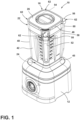
FIG. 1 is a top perspective view of a blender according to one aspect of the present disclosure; -
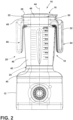
FIG. 2 is a front plan view of the blender ofFIG. 1 demonstrating a right-hand orientation of a container handle of the blender and a left-hand orientation of the container handle of the blender in phantom; -
FIG. 3 is a bottom perspective view of the blender ofFIG. 1 having a jar, at least a portion of a base, and a casing of the blender removed revealing an underside of an interface and a rod of the blender; -
FIG. 4 is a detailed view of an upper portion of the casing housing the rod shown inFIG. 3 ; -
FIG. 5 is a partial bottom perspective view of a container interacting with a carrier of a blender; -
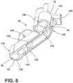
FIG. 6 is a bottom perspective view of an exemplary carrier for a blender according to one example of the present disclosure; -
FIG. 7A is a top perspective view of another exemplary carrier for a blender according to one example of the present disclosure; and -
FIG. 7B is a top perspective view of the carrier shown inFIG. 7A having a partial cross-sectional view of a hollow of the carrier. - The components in the figures are not necessarily to scale, emphasis instead being placed upon illustrating the principles described herein.
- The present illustrated embodiments reside primarily in combinations of method steps and apparatus components related to a multi-position blender. Accordingly, the apparatus components and method steps have been represented, where appropriate, by conventional symbols in the drawings, showing only those specific details that are pertinent to understanding the embodiments of the present disclosure so as not to obscure the disclosure with details that will be readily apparent to those of ordinary skill in the art having the benefit of the description herein. Further, like numerals in the description and drawings represent like elements.
- For purposes of description herein, the terms "upper," "lower," "right," "left," "rear," "front," "vertical," "horizontal," and derivatives thereof shall relate to the disclosure as oriented in
FIG. 1 . Unless stated otherwise, the term "front" shall refer to the surface of the element closer to an intended viewer, and the term "rear" shall refer to the surface of the element further from the intended viewer. However, it is to be understood that the disclosure may assume various alternative orientations, except where expressly specified to the contrary. It is also to be understood that the specific devices and processes illustrated in the attached drawings, and described in the following specification are simply exemplary embodiments of the inventive concepts defined in the appended claims. Hence, specific dimensions and other physical characteristics relating to the embodiments disclosed herein are not to be considered as limiting, unless the claims expressly state otherwise. - The terms "including," "comprises," "comprising," or any other variation thereof, are intended to cover a non-exclusive inclusion, such that a process, method, article, or apparatus that comprises a list of elements does not include only those elements but may include other elements not expressly listed or inherent to such process, method, article, or apparatus. An element preceded by "comprises a ... " does not, without more constraints, preclude the existence of additional identical elements in the process, method, article, or apparatus that comprises the element.
- Referring to
FIGS. 1-7B ,reference numeral 10 generally designates ablender 10. Theblender 10 includes abase 12 and asensor 14 disposed in thebase 12. Theblender 10 further includes acontainer 16 selectively coupled with thebase 12 in a firstrotational position 18 and in a secondrotational position 20. Thecontainer 16 has anupper portion 22 and alower portion 24. Alid 26 selectively engages theupper portion 22 of thecontainer 16. Theblender 10 further includes acarrier 30 in thelower portion 24. Thecarrier 30 extends between afirst end 32 and asecond end 34. Thecarrier 30 includes afirst magnet 36 disposed proximate thefirst end 32 and asecond magnet 38 disposed proximate thesecond end 34. Thesensor 14 is configured to detect thefirst magnet 36 in the firstrotational position 18 and thesecond magnet 38 in the secondrotational position 20. Theblender 10 may be any food processing apparatus operable to mix food items and/or liquefy, chop, cure, or otherwise process food items. - Referring now to
FIGS. 1 and2 , thecontainer 16 includes ajar 40 having asidewall 42 that extends between theupper portion 22 and thelower portion 24 of thecontainer 16. Thejar 40 may be optically transmissive to allow a user using theblender 10 to view contents of thecontainer 16. Thesidewall 42 extends along acentral axis 44 of thecontainer 16 which aligns with a motor in the base 12 that is configured to rotate food processing mechanisms, such as blades, about thecentral axis 44. For example, the motor may be mounted to aninterface 45, or jar pad, of thebase 12 for releasably coupling thecontainer 16 with thebase 12. Thesidewall 42 forms arim 46 at theupper portion 22 of thecontainer 16 that is configured to interact with thelid 26. For example, thelid 26 may have a sealed fit with thesidewall 42 at therim 46 to seal an interior of thecontainer 16. It is contemplated that other connections between thelid 26 and therim 46, such as a hinged connection, a threaded connection, or any other selective connection may be incorporated by theblender 10. - With continued reference to
FIGS. 1 and2 , therim 46 further forms aspout 48 disposed on afirst side 50 thecontainer 16 for pouring contents out of the interior. Ahandle 52 extends from thesidewall 42 at asecond side 54 of thecontainer 16, opposite thefirst side 50, to allow the user to manipulate thecontainer 16 when pouring contents out of thespout 48 or when removing or placing thecontainer 16 from/on thebase 12. Thelid 26 may further include aprojection 56 that extends from athird side 58 of thecontainer 16 at therim 46 and covers acasing 60 coupled with thesidewall 42. As will be described further herein, theprojection 56 may interact with thecarrier 30 in thelower portion 24. Thethird side 58 may be disposed between the first andsecond sides container 16. For example, thethird side 58 may be disposed at onecorner 62 of thecontainer 16 in examples in which thecontainer 16 forms a generally square-shaped cross-section of thesidewall 42. In this example, thehandle 52 and thespout 48 are also disposed atcorners 62 of thecontainer 16. The cross-sectional shape of thesidewall 42 is merely exemplary, and it is contemplated that other polygonal and/or arcuate-shaped cross-sections may be by thecontainer 16 of the present disclosure. - Referring now more particularly to
FIG. 2 , thehandle 52 may be operable to move thecontainer 16 relative to thebase 12. For example, thecontainer 16 may be lifted from thebase 12 via thehandle 52. When placing thecontainer 16 on thebase 12, the user may place thecontainer 16 in a right-hand orientation 64 or a left-hand orientation 66 of thehandle 52. The firstrotational position 18 of thecontainer 16 corresponds with the right-hand orientation 64 of thehandle 52, and the secondrotational position 20 of thecontainer 16 corresponds to the left-hand orientation 66 of thehandle 52. By providing for multiple positions to position thecontainer 16 on thebase 12, thepresent blender 10 may provide for enhanced usability while maintaining functional connection between thelid 26 and thecarrier 30 in thelower portion 24. In some examples, thejar 40 is keyed with the base 12 to provide limited orientations of thejar 40 relative to thebase 12. - Referring now to
FIG. 3 , a mount for a motor is provided along thecentral axis 44 in the underside of theinterface 45 and is configured to allow the motor to drive the food processing mechanisms through acentral aperture 68 in thelower portion 24. Thesensor 14 may be disposed adjacent the mount in the underside of theinterface 45 and include electrical conductors, orwires 70, extending into aholder 72 of thesensor 14. Theholder 72 may be directly coupled to abottom surface 74 of theinterface 45 and include areed switch 76 that is configured to detect a magnetic field from the first andsecond magnets sensor 14 is illustrated as being thereed switch 76 actuatable upon detection of the magnetic field, thesensor 14 may employ more or less sophisticated sensing devices. For example, thesensor 14 may incorporate a Hall-effect sensor 14 ormultiple reed switches 76 placed at different distances from thecarrier 30 to allow thesensor 14 to detect a strength of the magnetic field applied to thesensor 14. In such an example, thefirst magnet 36 may have a first magnetic field and thesecond magnet 38 may have a second magnetic field that is weaker or stronger in magnitude than the first magnetic field, and thesensor 14 may provide a signal indicating which of the orientations thecontainer 16 is in. Accordingly, thesensor 14 may be configured to differentiate between left-hand and right-hand orientations - Still referring to
FIG. 3 , thesensor 14 may be disposed adjacent to thethird side 58 near thecasing 60 of therod 80. In operation, thesensor 14 may be configured to align with one of thefirst magnet 36 and thesecond magnet 38 depending on the left-hand or right-hand orientations handle 52. For example, the first andsecond magnet sensor 14 in a direction parallel to thecentral axis 44. Stated differently, the first andsecond magnet sensor 14 depending on the orientation of thehandle 52. - Referring now to
FIGS. 3 and4 , atransmission mechanism 78, such as arod 80, extends between thelid 26 and the carrier 30 (FIGS. 5-7B ). Therod 80 is movable between an upward position and a downward position. Engagement of thelid 26 with theupper portion 22 to cover thecontainer 16 moves therod 80 toward the downward position. For example, aplunger 82 may mechanically interpose thelid 26 and therod 80. Thelid 26 covering thecontainer 16 moves therod 80 toward the downward position. Therod 80 extends between anupper end 84 and alower end 86. As will be described further herein, thelower end 86 mates with, or engages, thecarrier 30, such that movement of therod 80 causes movement of thecarrier 30. Thecasing 60 is disposed around therod 80 between thelower portion 24 and thelid 26 and may encase therod 80 and provide one ormore stabilizers 88 for therod 80 to allow translation of therod 80 between the upward and downward positions. Thestabilizer 88 may guide therod 80 through thecasing 60 and limit lateral movement of therod 80 to maintain alignment of therod 80 in thecasing 60. - Referring more particularly to
FIG. 4 , a biasingmember 90 extends between thecasing 60 and therod 80. The biasingmember 90 is configured to bias therod 80 toward the upward position. For example, therod 80 may define agroove 92 extending radially inwardly and receiving aclasp 94 that is axially locked with therod 80. Theclasp 94 may include adisc 96 that locks in thegroove 92. The biasingmember 90, which may be afirst spring 98, is sandwiched between theclasp 94 and one of thestabilizers 88 of thecasing 60. An expansion force caused by the coiled spring may cause the bias of therod 80 toward the upward position. When thelid 26 is secured to thecontainer 16 at theupper portion 22, theplunger 82 interposing thelid 26 and therod 80 at theupper end 84 drives therod 80 through thecasing 60. In this way, the force of thelid 26 on the plunger 82 (e.g., a sealing force with therim 46, a locking force of a threaded connection, gravity, etc.) drives therod 80 downward in response to interaction with thelid 26 to overcome the bias and push thecarrier 30 toward thebase 12. For example, theprojection 56 may engage theplunger 82 to push theupper end 84 of therod 80 downward and overcome the bias toward the upward position. Thus, upon securing thelid 26 with therim 46 of thecontainer 16, therod 80 is translated downwardly to cause thecarrier 30 to be translated downwardly toward thebase 12. - Referring now to
FIGS. 5 and6 , therod 80 may extend into thelower portion 24 at thelower end 86 via ahole 100 defined by acollar 102 of thelower portion 24. Thehole 100 may have an elongated shape to allow upward and downward movement of therod 80 in thelower portion 24. For example, as illustrated, thehole 100 may be oblong- or oval-shaped with a long axis of the oval/oblong shape extending vertically/parallel with thecentral axis 44. As shown inFIG. 6 , thecarrier 30 includes anelongated body 104 that defines aslot 106 configured to receive therod 80. Moving of therod 80 toward the downward position is operable to push thecarrier 30 for thesensor 14. For example, as therod 80 translates vertically, thecarrier 30 may also translate vertically to move themagnets base 12 and thesensor 14. Thus, when the first orsecond magnet 38 is aligned with thesensor 14, thesensor 14 may be limited from detecting the magnetic field caused by themagnets rod 80 being in the upward position. Likewise, thesensor 14 may be operable to detect the magnetic field of the first or thesecond magnet rod 80 being in the downward position and thehandle 52 being in the left-hand orientation 66 or the right-hand orientation 64. - Referring more particularly now to
FIG. 5 , thejar 40 includes alower wall 108 that defines acavity 110 configured to receive the food processing mechanisms in the interior and allow mechanical coupling of the food processing mechanisms with the motor and/or a mechanical interface between the food processing mechanisms and the motor. Amating connection 112 between thelower wall 108 of thejar 40 and thecarrier 30 is formed via at least onemale connector female connector lower wall 108 and thecarrier 30. In the illustrated example, the at least onemale connector male connector 114 and a secondmale connector 116, each extending downwardly from thelower wall 108 and engaging a firstfemale connector 118 and a secondfemale connector 120 formed on thecarrier 30, respectively. For example, the firstfemale connector 118 may be formed proximate to thefirst end 32 of thecarrier 30, and the secondfemale connector 120 may be formed adjacent thesecond end 34 of thecarrier 30. Themating connection 112 may be a keyed connection, such that only a specific arrangement or configuration between thejar 40 and thecarrier 30 may be achieved during assembly of thecontainer 16. Stated differently, the male andfemale connectors carrier 30 into thelower portion 24 of thejar 40. For example, the first male andfemale connectors female connectors jar 40 and the base 12 may be guided to limit improper assembly. - Although illustrated as a having an
arcuate portion 122 and astraight portion 124 of theelongated body 104, it is contemplated that any arcuate or straight shape of theelongated body 104 may be formed by thecarrier 30. It is further contemplated that, while the twomagnets hand orientations magnets carrier 30 without deviating from the present disclosure. For example, three positions may be achievable by using threemagnets carrier 30 and having three acceptable orientations for thehandle 52. In some examples, the first and secondrotational positions container 16 are between 90° and 180° from one another relative to thecentral axis 44 of thecontainer 16. However, it is contemplated that other rotational positions for theblender 10 may be anticipated by the present disclosure. - Referring again to
FIGS. 5 and6 , thecarrier 30 defines a first hollow 126 proximate thefirst end 32 and receiving thefirst magnet 36. Thecarrier 30 further defines a second hollow 128 proximate thesecond end 34 receiving thesecond magnet 38. For example, the hollow may be cylindrically- or tubularly-shaped and extend into an interactingface 130 of thecarrier 30. An adhesive, or another bonding member, may be deposited in one or both behind the correspondingfirst magnet 36 orsecond magnet 38. For example, the first andsecond magnet magnets magnets elongated body 104. An outer surface of themagnet face 130 of thecarrier 30. However, as will be described further herein, other components may be incorporated in each hollow 126, 128 to allow for adjustable movement of themagnet elongated body 104. - Referring now to
FIGS. 6-7B , theslot 106 defined by theelongated body 104 may extend along aprotrusion 132 substantially perpendicular to thecentral axis 44 of thecontainer 16. Accordingly, thelower end 86 of therod 80 may also extend substantially orthogonally relative the second axis to engage theslot 106 and link with thecarrier 30. It is contemplated that thestabilizers 88 of thecasing 60 previously described may maintain lateral securement of therod 80 to limit lateral movement of therod 80 and thereby limit therod 80 from becoming detached with theslot 106. - As demonstrated particularly in
FIG. 6 , theelongated body 104 may include arib 134 extending between two rails of theelongated body 104. Therib 134 may provide for structural rigidity between thefirst end 32 and thesecond end 34 of thecarrier 30. For example, when therod 80 translates vertically, each end of thecarrier 30 may translate with cantilever support from thefirst end 32 due to the structural rigidity of theelongated body 104 provided by therib 134. - Referring now more particularly to
FIGS. 7A and 7B , acap 136 may be disposed proximate each of thefirst end 32 and thesecond end 34 and may cover the first andsecond hollows second magnets cap 136 may be fastened with theelongated body 104 via one ormore fasteners 138 that are operable to engage theelongated body 104. For example, one ormore notches 140 may be defined by theelongated body 104 and be configured to mate with the one ormore fasteners 138 to provide a snap-fit connection between thecap 136 and theelongated body 104. The one ormore fasteners 138 may includehooks 142 that engage the one ormore notches 140 and limit removal and/or rotation of the caps relative to theelongated body 104. - Still referring to
FIGS. 7A and 7B , aresilient member 144, such as asecond spring 146, may be disposed in each hollow 126, 128 and configured to bias the corresponding first orsecond magnet elongated body 104. For example, atubular member 148 in which themagnets tubular member 148 may include aflange 150 configured to engage aledge 152 of the hollow 126, 128 in the extended position. Theresilient member 144 may push against thetubular member 148 to bias thetubular member 148 in the extended position. For example, thetubular member 148 may have a T-shaped cross-section that interacts with the hollow 126, 128 to allow for movement between the extended and retracted positions. Theledge 152 may limit an entirety of thetubular member 148 from moving out of the hollow 126, 128. For example, because theresilient member 144 is sandwiched between thetubular member 148 and thecap 136, an expansion force of theresilient member 144 pushes thetubular member 148 downwardly from thecap 136. However, due to an interaction between theflange 150 and theledge 152, thetubular member 148 may remain within the hollow 126, 128. - In operation, when the
lid 26 is placed on thecontainer 16, therod 80 translates downwardly causing thecarrier 30, along with thetubular members 148, to translate downwardly toward thebase 12. Abottom end 154 of thetubular member 148 may contact and engage thebase 12, thereby causing thetubular members 148 to move into the hollow 126, 128 and overcome the expansion force of theresilient member 144. Themagnet sensor 14 may thereby flag thesensor 14base 12 on the magnetic field. By providing the movabletubular member 148, and thereforemovable magnets - In general, the
present blender 10 may provide for dynamic and flexible usage without requiring enhanced manufacturing tolerances. For example, deviation from an expected movement of thelid 26, therod 80, thecarrier 30, or themagnets sensor 14 properly detecting attachment of thelid 26 to therim 46. By incorporating the various biasingmember 90 andresilient members 144, false readings by thesensor 14 may be limited, and proper detection of the right-hand or left-hand orientations blender 10 of the present disclosure. - According to an aspect of the present disclosure, a blender includes a base. The blender further includes a sensor disposed in the base. The blender further includes a container selectively coupled with the base in a first rotational position and in a second rotational position. The container has an upper portion and a lower portion. The blender further includes a lid that selectively engages the upper portion of the container. The blender further includes a carrier in the lower portion that extends between a first end and a second end. The carrier includes a first magnet disposed proximate the first end. The carrier further includes a second magnet disposed proximate the second end. The sensor is configured to detect the first magnet in the first rotational position and the second magnet in the second rotational position.
- According to another aspect of the present disclosure, the blender includes a rod extending between the lid and the carrier. The rod is moveable between an upward position and a downward position. The lid engaging the upper portion of the container moves the rod toward the downward position.
- According to yet another aspect of the present disclosure, the blender includes an elongated body that defines a slot configured to receive the rod. The moving of the rod toward the downward position is operable to push the carrier toward the sensor.
- According to another aspect of the present disclosure, the sensor is limited from detecting a magnetic field of the first and second magnets in response to the rod being in the upward position.
- According to yet another aspect of the present disclosure, the carrier defines a first hollow proximate the first end and receiving the first magnet and a second hollow proximate the second end and receiving the second magnet.
- According to another aspect of the present disclosure, the blender further includes a resilient member disposed in the first hollow configured to bias the first magnet away from the elongated body.
- According to yet another aspect of the present disclosure, the blender further includes a tubular member moveable in the first hollow and holding the first magnet.
- According to another aspect of the present disclosure, the tubular member is configured to engage the base in response to the bias of the first magnet away from the elongated body.
- According to yet another aspect of the present disclosure, the blender further includes a cap disposed proximate each of the first end and the second end and covering the first and second hollows above the first and second magnets.
- According to another aspect of the present disclosure, the resilient member is sandwiched between the tubular member and the cap.
- According to yet another aspect of the present disclosure, the blender further includes a casing disposed around the rod between the lower portion and the lid. The blender further includes a biasing member extending between the casing and the rod and configured to bias the rod toward the upward position.
- According to another aspect of the present disclosure, the blender further includes a plunger mechanically interposing the lid and the rod and configured to drive the rod through the casing when the lid is secured at the upper portion.
- According to yet another aspect of the present disclosure, the sensor is a reed switch.
- According to yet another aspect of the present disclosure, the blender further includes a handle operable to move the container relative to the base. The first rotational position corresponds to a right-hand orientation of the handle and the second rotational position corresponds to a left-hand orientation of the handle.
- According to another aspect of the present disclosure, the carrier has an elongated body between the first end and the second end to allow the first magnet to align with the sensor in the right-hand orientation and to allow the second magnet to align with the sensor in the left-hand orientation.
- According to yet another aspect of the present disclosure, a blender includes a base and a sensor disposed in the base. The blender further includes a container selectively coupled with the base in a first rotational position and in a second rotational position. The blender further includes a carrier extending between a first end and a second end. A first magnet is disposed proximate the first end. A second magnet is disposed proximate the second end. The sensor is configured to detect the first magnet in the first rotational position and the second magnet in the second rotational position.
- According to another aspect of the present disclosure, the blender further includes a handle for moving the container relative to the base. The first rotational position corresponds to a right-hand orientation of the handle and the second rotational position corresponds to a left-hand orientation of the handle.
- According to yet another aspect of the present disclosure, the carrier has an elongated body between the first end and the second end to allow the first magnet to align with the sensor in the right-hand orientation and to allow the second magnet to align with the sensor in the left-hand orientation.
- According to another aspect of the present disclosure, the blender further includes a rod extending between the lid and the carrier. The rod is moveable between an upward position and a downward position. The lid engaging the upper portion of the container moves the rod toward the downward position.
- According to yet another aspect of the present disclosure, a blender includes a base and a reed switch disposed in the base. A container selectively couples with the base in a first rotational position and in a second rotational position. The container has an upper portion and a lower portion. A lid selectively engages the upper portion of the container. A handle is operable to move the container relative to the base. The first rotational position corresponds to a right-hand orientation of the handle and the second rotational position corresponds to a left-hand orientation of the handle. A carrier is in the lower portion and extends between a first end and a second end. The carrier includes a first magnet disposed proximate the first end and a second magnet disposed proximate the second end. The sensor is configured to detect the first magnet in the first rotational position and the second magnet in the second rotational position. The carrier further includes an elongated body between the first end and the second end to allow the first magnet to align with the sensor in the right-hand orientation and to allow the second magnet to align with the sensor in the left-hand orientation.
- It will be understood by one having ordinary skill in the art that construction of the described disclosure and other components is not limited to any specific material. Other exemplary embodiments of the disclosure disclosed herein may be formed from a wide variety of materials, unless described otherwise herein.
- For purposes of this disclosure, the term "coupled" (in all of its forms, couple, coupling, coupled, etc.) generally means the joining of two components (electrical or mechanical) directly or indirectly to one another. Such joining may be stationary in nature or movable in nature. Such joining may be achieved with the two components (electrical or mechanical) and any additional intermediate members being integrally formed as a single unitary body with one another or with the two components. Such joining may be permanent in nature or may be removable or releasable in nature unless otherwise stated.
- It is also important to note that the construction and arrangement of the elements of the disclosure as shown in the exemplary embodiments is illustrative only. Although only a few embodiments of the present innovations have been described in detail in this disclosure, those skilled in the art who review this disclosure will readily appreciate that many modifications are possible (e.g., variations in sizes, dimensions, structures, shapes and proportions of the various elements, values of parameters, mounting arrangements, use of materials, colors, orientations, etc.) without materially departing from the novel teachings and advantages of the subject matter recited. For example, elements shown as integrally formed may be constructed of multiple parts or elements shown as multiple parts may be integrally formed, the operation of the interfaces may be reversed or otherwise varied, the length or width of the structures and/or members or connector or other elements of the system may be varied, the nature or number of adjustment positions provided between the elements may be varied. It should be noted that the elements and/or assemblies of the system may be constructed from any of a wide variety of materials that provide sufficient strength or durability, in any of a wide variety of colors, textures, and combinations. Accordingly, all such modifications are intended to be included within the scope of the present innovations. Other substitutions, modifications, changes, and omissions may be made in the design, operating conditions, and arrangement of the desired and other exemplary embodiments without departing from the spirit of the present innovations.
- It will be understood that any described processes or steps within described processes may be combined with other disclosed processes or steps to form structures within the scope of the present disclosure. The exemplary structures and processes disclosed herein are for illustrative purposes and are not to be construed as limiting.
Claims (15)
- A blender (10) comprising:a base (12);a sensor (14) disposed in the base (12);a container (16) selectively coupled with the base (12) in a first rotational position (18) and in a second rotational position (20); anda carrier (30) extending between a first end (32) and a second end (34),wherein the carrier (30) includes:a first magnet (36) disposed proximate the first end (32); anda second magnet (38) disposed proximate the second end (34), andwherein the sensor (14) is configured to detect the first magnet (36) in the first rotational position (18) and the second magnet (38) in the second rotational position (20).
- The blender (10) of claim 1, wherein the container (16) has an upper portion (22) and a lower portion (24), wherein the blender (10) further comprises a lid (26) selectively engaging the upper portion (22) of the container (16); and wherein the carrier (30) is disposed in the lower portion (24) of the container (16).
- The blender (10) of claim 2, further comprising a rod (80) extending between the lid (26) and the carrier (30), the rod (80) being moveable between an upward position and a downward position, wherein the lid (26) engaging the upper portion (22) of the container (16) moves the rod (80) toward the downward position, optionally wherein the carrier (30) includes an elongated body (104) that defines a slot (106) configured to receive the rod (80) and/or optionally wherein the moving of the rod (80) toward the downward position is operable to push the carrier (30) toward the sensor (14).
- The blender (10) of any one of claims 1-3, wherein the sensor (10) is limited from detecting a magnetic field of the first and second magnets (36, 38) in response to the rod (80) being in the upward position and/or wherein the carrier (30) is configured to be translated downwardly from a first height to a second height, optionally wherein the sensor (10) is limited from detecting a magnetic field of the first and second magnets (36, 38) in response to the carrier (30) being at the first height.
- The blender (10) of any one of claims 1-4, wherein the carrier (30) defines a first hollow (126) proximate the first end (32) and receiving the first magnet (36) and/or a second hollow (128) proximate the second end (34) and receiving the second magnet (38) and/or wherein the first magnet (36) and/or the second magnet (38) are movably coupled to the carrier (30) so that the first and second magnets (36, 38) may selectively assume respective raised and lowered positions.
- The blender (10) of claim 5, further comprising a first resilient member (144) disposed in the first hollow (126) configured to bias the first magnet (36) away from the elongated body (104) and/or a second resilient member (144) disposed in the second hollow (128) configured to bias the second magnet (38) away from the elongated body (104).
- The blender (10) of either one of claim 5 or claim 6, further comprising a first tubular member (148) moveable in the first hollow (126) and holding the first magnet (36) and/or a second tubular member (148) moveable in the second hollow (128) and holding the second magnet (38).
- The blender (10) of claim 7, wherein the first tubular member (148) is configured to engage the base (12) in response to the bias of the first magnet (36) away from the elongated body (104) and/or wherein the second tubular member (148) is configured to engage the base (12) in response to the bias of the second magnet (38) away from the elongated body (104).
- The blender (10) of claim 8, further comprising a first cap (136) disposed proximate the first end (32) and covering the first hollow (126) above the first magnet (36) and/or a second cap (136) disposed proximate the second end (34) and covering the second hollow (128) above the second magnet (38), optionally wherein the first resilient member (144) is sandwiched between the first tubular member (148) and the first cap (136) and/or optionally wherein the second resilient member (144) is sandwiched between the second tubular member (148) and the second cap (136).
- The blender (10) of any one of claims 1-9, wherein the first magnet (36) has a first magnetic field and wherein the second magnet (38) has a second magnetic field that is weaker or stronger in magnitude than the first magnetic field.
- The blender (10) of any one of claims 3-10, further comprising:a biasing member (90) configured to bias the rod (80) toward the upward position and/ora plunger (82) mechanically interposing the lid (26) and the rod (80) and configured to drive the rod (80) when the lid (26) is secured at the upper portion (22) of the container (16).
- The blender (10) of any one of claims 3-11, further comprising a casing (60) disposed around the rod (80) between the lower portion (24) of the container and the lid (26), optionally wherein the biasing member (90) extends between the casing (60) and the rod (80) and configured to bias the rod (80) toward the upward position and/or optionally wherein the plunger (82) is configured to drive the rod (80) through the casing (60) when the lid (26) is secured at the upper portion (22).
- The blender (10) of any one of claims 1-12, wherein the sensor (14) is a reed switch (76).
- The blender (10) of any one of claims 1-13, further comprising a handle (52) operable to move the container (16) relative to the base (12), wherein the first rotational position (18) corresponds to a right-hand orientation (64) of the handle (52) and the second rotational position (20) corresponds to a left-hand orientation (66) of the handle (52).
- The blender (10) of claim 14, wherein the carrier (30) has an elongated body (104) between the first end (32) and the second end (34) to allow the first magnet (36) to align with the sensor (14) in the right-hand orientation (64) and to allow the second magnet (38) to align with the sensor (14) in the left-hand orientation (66).
Applications Claiming Priority (1)
| Application Number | Priority Date | Filing Date | Title |
|---|---|---|---|
| US18/137,558 US20240349948A1 (en) | 2023-04-21 | 2023-04-21 | Multi-position blender |
Publications (1)
| Publication Number | Publication Date |
|---|---|
| EP4449958A1 true EP4449958A1 (en) | 2024-10-23 |
Family
ID=90880549
Family Applications (1)
| Application Number | Title | Priority Date | Filing Date |
|---|---|---|---|
| EP24171691.9A Pending EP4449958A1 (en) | 2023-04-21 | 2024-04-22 | Multi-position blender |
Country Status (4)
| Country | Link |
|---|---|
| US (1) | US20240349948A1 (en) |
| EP (1) | EP4449958A1 (en) |
| CN (1) | CN118806126A (en) |
| AU (1) | AU2024202603A1 (en) |
Citations (4)
| Publication number | Priority date | Publication date | Assignee | Title |
|---|---|---|---|---|
| FR2464047A1 (en) * | 1979-08-29 | 1981-03-06 | Robot Coupe Sa | Magnetic safety device for food chopper - has motor switch operable only when bin and lid are secured |
| FR2488038A1 (en) * | 1980-07-31 | 1982-02-05 | Robot Coupe Sa | Magnetic safety device for food chopper - has motor switch operable only when bin and lid are secured |
| WO2007023116A1 (en) * | 2005-08-26 | 2007-03-01 | BSH Bosch und Siemens Hausgeräte GmbH | Kitchen appliance comprising a magnetic safety lock |
| WO2022207237A1 (en) * | 2021-04-01 | 2022-10-06 | De'longhi Braun Household Gmbh | Kitchen appliance |
Family Cites Families (1)
| Publication number | Priority date | Publication date | Assignee | Title |
|---|---|---|---|---|
| US11426032B2 (en) * | 2016-10-31 | 2022-08-30 | Vita-Mix Management Corporation | Centering pad and removable enclosure for a blender |
-
2023
- 2023-04-21 US US18/137,558 patent/US20240349948A1/en active Pending
-
2024
- 2024-04-20 AU AU2024202603A patent/AU2024202603A1/en active Pending
- 2024-04-22 CN CN202410485705.0A patent/CN118806126A/en active Pending
- 2024-04-22 EP EP24171691.9A patent/EP4449958A1/en active Pending
Patent Citations (4)
| Publication number | Priority date | Publication date | Assignee | Title |
|---|---|---|---|---|
| FR2464047A1 (en) * | 1979-08-29 | 1981-03-06 | Robot Coupe Sa | Magnetic safety device for food chopper - has motor switch operable only when bin and lid are secured |
| FR2488038A1 (en) * | 1980-07-31 | 1982-02-05 | Robot Coupe Sa | Magnetic safety device for food chopper - has motor switch operable only when bin and lid are secured |
| WO2007023116A1 (en) * | 2005-08-26 | 2007-03-01 | BSH Bosch und Siemens Hausgeräte GmbH | Kitchen appliance comprising a magnetic safety lock |
| WO2022207237A1 (en) * | 2021-04-01 | 2022-10-06 | De'longhi Braun Household Gmbh | Kitchen appliance |
Also Published As
| Publication number | Publication date |
|---|---|
| CN118806126A (en) | 2024-10-22 |
| AU2024202603A1 (en) | 2024-11-07 |
| US20240349948A1 (en) | 2024-10-24 |
Similar Documents
| Publication | Publication Date | Title |
|---|---|---|
| EP2781465B1 (en) | Detachable sealable lid, container comprising the same and sealing ring for use with the lid | |
| US20090205876A1 (en) | Digital Scale with Magnetic Engagement of a User Interface Unit | |
| US9924847B2 (en) | Self-propelled working device | |
| EP2404536B1 (en) | Work container comprising a removable base and household cooking appliance equipped with such a container | |
| KR20170127437A (en) | Container with sealable lid | |
| EP3821774B1 (en) | Food processor | |
| UA126973C2 (en) | MIXER WITH PREVENTIVE MECHANISMS | |
| EP3053489B1 (en) | Vacuum coffee maker with magnetic coupling system | |
| KR101411685B1 (en) | Vacuum cleaner | |
| US9321564B2 (en) | Mechanically secured lid and container | |
| CN111433132B (en) | Containers with sealable lids | |
| CN111989272B (en) | Single use food preparation container assemblies, systems, and methods | |
| US20200055383A1 (en) | Locking device, fixed base and electric vehicle | |
| WO2018140498A1 (en) | Food processor lid | |
| US20240349948A1 (en) | Multi-position blender | |
| BRMU8800469Y1 (en) | cup coupler and locking mechanism and blender / processor base | |
| US12497218B1 (en) | Straw cup | |
| CN110772114A (en) | Pot cover and cooking utensil and pressure cooker including same | |
| EP3552527B1 (en) | Kettle lid and kettle with same | |
| CN100449664C (en) | Switches with multi-directional heads | |
| US20240374090A1 (en) | Quick release structure for toilet lid | |
| CN119532288A (en) | Magnetic buckle and water bottle device | |
| KR101750798B1 (en) | Blender | |
| US20240041266A1 (en) | Frying basket with detachable handle and air fryer | |
| GB2245251A (en) | Collapsible containers |
Legal Events
| Date | Code | Title | Description |
|---|---|---|---|
| PUAI | Public reference made under article 153(3) epc to a published international application that has entered the european phase |
Free format text: ORIGINAL CODE: 0009012 |
|
| STAA | Information on the status of an ep patent application or granted ep patent |
Free format text: STATUS: THE APPLICATION HAS BEEN PUBLISHED |
|
| AK | Designated contracting states |
Kind code of ref document: A1 Designated state(s): AL AT BE BG CH CY CZ DE DK EE ES FI FR GB GR HR HU IE IS IT LI LT LU LV MC ME MK MT NL NO PL PT RO RS SE SI SK SM TR |
|
| STAA | Information on the status of an ep patent application or granted ep patent |
Free format text: STATUS: REQUEST FOR EXAMINATION WAS MADE |
|
| 17P | Request for examination filed |
Effective date: 20250423 |