EP4446729A2 - Vorrichtung und verfahren zur messung von gas und partikeln unter verwendung eines optischen strahls - Google Patents
Vorrichtung und verfahren zur messung von gas und partikeln unter verwendung eines optischen strahls Download PDFInfo
- Publication number
- EP4446729A2 EP4446729A2 EP24162870.0A EP24162870A EP4446729A2 EP 4446729 A2 EP4446729 A2 EP 4446729A2 EP 24162870 A EP24162870 A EP 24162870A EP 4446729 A2 EP4446729 A2 EP 4446729A2
- Authority
- EP
- European Patent Office
- Prior art keywords
- gas
- particulate
- data
- optical
- photodetector
- Prior art date
- Legal status (The legal status is an assumption and is not a legal conclusion. Google has not performed a legal analysis and makes no representation as to the accuracy of the status listed.)
- Pending
Links
Images


Classifications
-
- G—PHYSICS
- G01—MEASURING; TESTING
- G01N—INVESTIGATING OR ANALYSING MATERIALS BY DETERMINING THEIR CHEMICAL OR PHYSICAL PROPERTIES
- G01N21/00—Investigating or analysing materials by the use of optical means, i.e. using sub-millimetre waves, infrared, visible or ultraviolet light
- G01N21/17—Systems in which incident light is modified in accordance with the properties of the material investigated
- G01N21/25—Colour; Spectral properties, i.e. comparison of effect of material on the light at two or more different wavelengths or wavelength bands
- G01N21/31—Investigating relative effect of material at wavelengths characteristic of specific elements or molecules, e.g. atomic absorption spectrometry
-
- G—PHYSICS
- G01—MEASURING; TESTING
- G01J—MEASUREMENT OF INTENSITY, VELOCITY, SPECTRAL CONTENT, POLARISATION, PHASE OR PULSE CHARACTERISTICS OF INFRARED, VISIBLE OR ULTRAVIOLET LIGHT; COLORIMETRY; RADIATION PYROMETRY
- G01J3/00—Spectrometry; Spectrophotometry; Monochromators; Measuring colours
- G01J3/02—Details
- G01J3/0205—Optical elements not provided otherwise, e.g. optical manifolds, diffusers, windows
-
- G—PHYSICS
- G01—MEASURING; TESTING
- G01J—MEASUREMENT OF INTENSITY, VELOCITY, SPECTRAL CONTENT, POLARISATION, PHASE OR PULSE CHARACTERISTICS OF INFRARED, VISIBLE OR ULTRAVIOLET LIGHT; COLORIMETRY; RADIATION PYROMETRY
- G01J3/00—Spectrometry; Spectrophotometry; Monochromators; Measuring colours
- G01J3/28—Investigating the spectrum
- G01J3/42—Absorption spectrometry; Double beam spectrometry; Flicker spectrometry; Reflection spectrometry
-
- G—PHYSICS
- G01—MEASURING; TESTING
- G01J—MEASUREMENT OF INTENSITY, VELOCITY, SPECTRAL CONTENT, POLARISATION, PHASE OR PULSE CHARACTERISTICS OF INFRARED, VISIBLE OR ULTRAVIOLET LIGHT; COLORIMETRY; RADIATION PYROMETRY
- G01J3/00—Spectrometry; Spectrophotometry; Monochromators; Measuring colours
- G01J3/28—Investigating the spectrum
- G01J3/44—Raman spectrometry; Scattering spectrometry ; Fluorescence spectrometry
- G01J3/4412—Scattering spectrometry
-
- G—PHYSICS
- G01—MEASURING; TESTING
- G01J—MEASUREMENT OF INTENSITY, VELOCITY, SPECTRAL CONTENT, POLARISATION, PHASE OR PULSE CHARACTERISTICS OF INFRARED, VISIBLE OR ULTRAVIOLET LIGHT; COLORIMETRY; RADIATION PYROMETRY
- G01J3/00—Spectrometry; Spectrophotometry; Monochromators; Measuring colours
- G01J3/28—Investigating the spectrum
- G01J3/45—Interferometric spectrometry
-
- G—PHYSICS
- G01—MEASURING; TESTING
- G01J—MEASUREMENT OF INTENSITY, VELOCITY, SPECTRAL CONTENT, POLARISATION, PHASE OR PULSE CHARACTERISTICS OF INFRARED, VISIBLE OR ULTRAVIOLET LIGHT; COLORIMETRY; RADIATION PYROMETRY
- G01J3/00—Spectrometry; Spectrophotometry; Monochromators; Measuring colours
- G01J3/28—Investigating the spectrum
- G01J3/45—Interferometric spectrometry
- G01J3/453—Interferometric spectrometry by correlation of the amplitudes
- G01J3/4531—Devices without moving parts
-
- G—PHYSICS
- G01—MEASURING; TESTING
- G01N—INVESTIGATING OR ANALYSING MATERIALS BY DETERMINING THEIR CHEMICAL OR PHYSICAL PROPERTIES
- G01N15/00—Investigating characteristics of particles; Investigating permeability, pore-volume or surface-area of porous materials
- G01N15/02—Investigating particle size or size distribution
- G01N15/0205—Investigating particle size or size distribution by optical means
-
- G—PHYSICS
- G01—MEASURING; TESTING
- G01N—INVESTIGATING OR ANALYSING MATERIALS BY DETERMINING THEIR CHEMICAL OR PHYSICAL PROPERTIES
- G01N15/00—Investigating characteristics of particles; Investigating permeability, pore-volume or surface-area of porous materials
- G01N15/06—Investigating concentration of particle suspensions
-
- G—PHYSICS
- G01—MEASURING; TESTING
- G01N—INVESTIGATING OR ANALYSING MATERIALS BY DETERMINING THEIR CHEMICAL OR PHYSICAL PROPERTIES
- G01N15/00—Investigating characteristics of particles; Investigating permeability, pore-volume or surface-area of porous materials
- G01N15/06—Investigating concentration of particle suspensions
- G01N15/075—Investigating concentration of particle suspensions by optical means
-
- G—PHYSICS
- G01—MEASURING; TESTING
- G01N—INVESTIGATING OR ANALYSING MATERIALS BY DETERMINING THEIR CHEMICAL OR PHYSICAL PROPERTIES
- G01N21/00—Investigating or analysing materials by the use of optical means, i.e. using sub-millimetre waves, infrared, visible or ultraviolet light
- G01N21/01—Arrangements or apparatus for facilitating the optical investigation
- G01N21/03—Cuvette constructions
- G01N21/031—Multipass arrangements
-
- G—PHYSICS
- G01—MEASURING; TESTING
- G01N—INVESTIGATING OR ANALYSING MATERIALS BY DETERMINING THEIR CHEMICAL OR PHYSICAL PROPERTIES
- G01N21/00—Investigating or analysing materials by the use of optical means, i.e. using sub-millimetre waves, infrared, visible or ultraviolet light
- G01N21/17—Systems in which incident light is modified in accordance with the properties of the material investigated
- G01N21/25—Colour; Spectral properties, i.e. comparison of effect of material on the light at two or more different wavelengths or wavelength bands
- G01N21/31—Investigating relative effect of material at wavelengths characteristic of specific elements or molecules, e.g. atomic absorption spectrometry
- G01N21/314—Investigating relative effect of material at wavelengths characteristic of specific elements or molecules, e.g. atomic absorption spectrometry with comparison of measurements at specific and non-specific wavelengths
-
- G—PHYSICS
- G01—MEASURING; TESTING
- G01N—INVESTIGATING OR ANALYSING MATERIALS BY DETERMINING THEIR CHEMICAL OR PHYSICAL PROPERTIES
- G01N21/00—Investigating or analysing materials by the use of optical means, i.e. using sub-millimetre waves, infrared, visible or ultraviolet light
- G01N21/17—Systems in which incident light is modified in accordance with the properties of the material investigated
- G01N21/25—Colour; Spectral properties, i.e. comparison of effect of material on the light at two or more different wavelengths or wavelength bands
- G01N21/31—Investigating relative effect of material at wavelengths characteristic of specific elements or molecules, e.g. atomic absorption spectrometry
- G01N21/39—Investigating relative effect of material at wavelengths characteristic of specific elements or molecules, e.g. atomic absorption spectrometry using tunable lasers
-
- G—PHYSICS
- G01—MEASURING; TESTING
- G01N—INVESTIGATING OR ANALYSING MATERIALS BY DETERMINING THEIR CHEMICAL OR PHYSICAL PROPERTIES
- G01N21/00—Investigating or analysing materials by the use of optical means, i.e. using sub-millimetre waves, infrared, visible or ultraviolet light
- G01N21/17—Systems in which incident light is modified in accordance with the properties of the material investigated
- G01N21/47—Scattering, i.e. diffuse reflection
- G01N21/49—Scattering, i.e. diffuse reflection within a body or fluid
- G01N21/53—Scattering, i.e. diffuse reflection within a body or fluid within a flowing fluid, e.g. smoke
-
- G—PHYSICS
- G01—MEASURING; TESTING
- G01N—INVESTIGATING OR ANALYSING MATERIALS BY DETERMINING THEIR CHEMICAL OR PHYSICAL PROPERTIES
- G01N33/00—Investigating or analysing materials by specific methods not covered by groups G01N1/00 - G01N31/00
- G01N33/0004—Gaseous mixtures, e.g. polluted air
- G01N33/0009—General constructional details of gas analysers, e.g. portable test equipment
- G01N33/0027—General constructional details of gas analysers, e.g. portable test equipment concerning the detector
-
- G—PHYSICS
- G01—MEASURING; TESTING
- G01N—INVESTIGATING OR ANALYSING MATERIALS BY DETERMINING THEIR CHEMICAL OR PHYSICAL PROPERTIES
- G01N15/00—Investigating characteristics of particles; Investigating permeability, pore-volume or surface-area of porous materials
- G01N2015/0042—Investigating dispersion of solids
- G01N2015/0046—Investigating dispersion of solids in gas, e.g. smoke
-
- G—PHYSICS
- G01—MEASURING; TESTING
- G01N—INVESTIGATING OR ANALYSING MATERIALS BY DETERMINING THEIR CHEMICAL OR PHYSICAL PROPERTIES
- G01N21/00—Investigating or analysing materials by the use of optical means, i.e. using sub-millimetre waves, infrared, visible or ultraviolet light
- G01N21/01—Arrangements or apparatus for facilitating the optical investigation
- G01N2021/0106—General arrangement of respective parts
- G01N2021/0118—Apparatus with remote processing
-
- G—PHYSICS
- G01—MEASURING; TESTING
- G01N—INVESTIGATING OR ANALYSING MATERIALS BY DETERMINING THEIR CHEMICAL OR PHYSICAL PROPERTIES
- G01N21/00—Investigating or analysing materials by the use of optical means, i.e. using sub-millimetre waves, infrared, visible or ultraviolet light
- G01N21/17—Systems in which incident light is modified in accordance with the properties of the material investigated
- G01N21/25—Colour; Spectral properties, i.e. comparison of effect of material on the light at two or more different wavelengths or wavelength bands
- G01N21/31—Investigating relative effect of material at wavelengths characteristic of specific elements or molecules, e.g. atomic absorption spectrometry
- G01N21/39—Investigating relative effect of material at wavelengths characteristic of specific elements or molecules, e.g. atomic absorption spectrometry using tunable lasers
- G01N2021/391—Intracavity sample
-
- G—PHYSICS
- G01—MEASURING; TESTING
- G01N—INVESTIGATING OR ANALYSING MATERIALS BY DETERMINING THEIR CHEMICAL OR PHYSICAL PROPERTIES
- G01N21/00—Investigating or analysing materials by the use of optical means, i.e. using sub-millimetre waves, infrared, visible or ultraviolet light
- G01N21/17—Systems in which incident light is modified in accordance with the properties of the material investigated
- G01N21/25—Colour; Spectral properties, i.e. comparison of effect of material on the light at two or more different wavelengths or wavelength bands
-
- G—PHYSICS
- G01—MEASURING; TESTING
- G01N—INVESTIGATING OR ANALYSING MATERIALS BY DETERMINING THEIR CHEMICAL OR PHYSICAL PROPERTIES
- G01N21/00—Investigating or analysing materials by the use of optical means, i.e. using sub-millimetre waves, infrared, visible or ultraviolet light
- G01N21/17—Systems in which incident light is modified in accordance with the properties of the material investigated
- G01N21/47—Scattering, i.e. diffuse reflection
- G01N21/49—Scattering, i.e. diffuse reflection within a body or fluid
- G01N21/53—Scattering, i.e. diffuse reflection within a body or fluid within a flowing fluid, e.g. smoke
- G01N21/532—Scattering, i.e. diffuse reflection within a body or fluid within a flowing fluid, e.g. smoke with measurement of scattering and transmission
Definitions
- Example embodiments of the present disclosure relate generally to monitoring air quality within an environment and, more particularly, to apparatuses and methods for detecting and characterizing gases and particulate matter within a designated environment.
- Applicant has identified many technical challenges and difficulties associated with simultaneously detecting gases and particulate matter within the same environment. For example, many methods and systems fail to allow for a singular sensing device to detect both a gas concentration and a particulate matter concentration within the common environment.
- a method of detecting one or more gases and particulate matter within a sensing region may comprise emitting, from a beam component, an optical beam along a beam path defined at least partially within a sensing region; detecting particulate matter within the sensing region based at least in part on particulate data generated by one or more photodetector, the particulate data being defined at least in part by a detection of a scattered portion of the optical beam reflected from a particulate positioned along the beam path; and detecting a first gas within the sensing region based at least in part on gas data generated by the beam component, wherein the gas data is generated by the beam component via an optical gas sensing means, and wherein the gas data is defined at least in part by a detected absorption of at least a portion of the optical beam at a first wavelength corresponding to the first gas.
- the optical beam may embody an active optical beam that is pulsed from the beam component such that the active optical beam defines an optical pulse rate.
- the method may further comprise executing a data processing operation wherein a photodetector signal defined at least in part by the particulate data generated by the one or more photodetectors is processed with the optical pulse rate using a phase-locked loop to enhance the photodetector signal by at least partially reducing signal noise.
- the optical gas sensing means may be a dual-frequency comb spectroscopy operation.
- the gas data generated by the beam component may comprise a frequency-comb data stream including at least a first wavelength and a second wavelength.
- the method may further comprise providing a color filter relative to the one or more photodetectors such that the scattered portion of the optical beam is passed through the color filter.
- the method may further comprise transmitting the particulate data generated by the one or more photodetector to a controller, and determining, via the controller, a particulate matter concentration associated with the particulate matter based at least in part on the particulate data.
- the method may further comprise transmitting the gas data generated by the beam component to a controller, and determining, via the controller, a gas concentration associated with the first gas based at least in part on the gas data.
- the gas data may be further defined by an absorption intensity defined at the first wavelength, and wherein the gas concentration associated with the first gas is determined based at least in part on the absorption intensity defined at least at the first wavelength.
- the one or more photodetectors may define a plurality of photodetectors, and wherein the method further comprises determining a cumulative particulate matter concentration based on the respective particulate data generated by each of the plurality of photodetectors.
- the beam path defined by the optical beam may define a looped path configuration, wherein the beam path is defined along two or more distinct linear axes.
- the beam path defined by the optical beam may define a retro-reflection path configuration, wherein the beam path is defined along a single axis between the beam component and a reflective element configured to reflect the optical beam towards the beam component.
- the optical beam may be emitted in an emission direction at least substantially towards a mobile reflection platform configured for movement relative to the beam component such that the beam path defines a dynamic configuration.
- the method may further comprise detecting a movement of the mobile reflection platform from a first position to a second position relative to the beam component; and at least partially adjusting the emission direction defined by the beam path such that at least a portion of the beam path is defined along an axis oriented between the beam component and the second position of the mobile reflection platform.
- a sensor configured for detecting one or more gases and particulate matter may comprise a beam component configured to emit an optical beam along a beam path defined at least partially within a sensing region of a sensor, wherein the beam component is further configured to generate gas data associated with a first gas positioned the sensing region via an optical gas sensing means; one or more photodetector configured to generate particulate data defined at least in part by a detection of a scattered portion of the optical beam reflected off a particulate positioned along the beam path; and a controller configured to detect particulate matter within sensing region based at least in part on the particulate data generated by the one or more photodetector, and detect the first gas based at least in part on the gas data generated by the beam component, wherein the gas data is defined at least in part by a detected absorption of at least a portion of the optical beam at a first wavelength corresponding to the first gas.
- the optical beam may embody an active optical beam that is pulsed from the beam component such that the active optical beam defines an optical pulse rate.
- the controller may be further configured to execute a data processing operation wherein a photodetector signal defined at least in part by the particulate data generated by the one or more photodetectors is processed with the optical pulse rate using a phase-locked loop to enhance the photodetector signal by at least partially reducing signal noise.
- the optical gas sensing means may be a dual-frequency comb spectroscopy operation.
- the gas data generated by the beam component may comprise a frequency-comb data stream including at least a first wavelength and a second wavelength.
- the one or more photodetectors may define a plurality of photodetectors each oriented to face in a direction at least substantially towards a respective portion of the beam path and configured to generate respective particulate data defined at least in part by respective detections of scattered optical beam light reflected from one or more particulates positioned at the respective portion of the beam path adjacent the respective photodetector.
- the term "comprising” means including but not limited to and should be interpreted in the manner it is typically used in the patent context. Use of broader terms such as comprises, includes, and having should be understood to provide support for narrower terms such as consisting of, consisting essentially of, and comprised substantially of.
- ком ⁇ онент or feature may,” “can,” “could,” “should,” “would,” “preferably,” “possibly,” “typically,” “optionally,” “for example,” “often,” or “might” (or other such language) be included or have a characteristic, that a specific component or feature is not required to be included or to have the characteristic. Such a component or feature may be optionally included in some embodiments, or it may be excluded.
- electroctronically coupled refers to two or more elements or components being connected through wired means and/or wireless means, such that signals, electrical voltage/current, data and/or information may be transmitted to and/or received from one of these components.
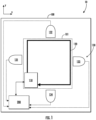
- FIG. 1 illustrates a schematic view of an exemplary gas sensor in accordance with various embodiments of the present disclosure.
- FIG. 1 illustrates an exemplary sensor 10 configured to execute a gas sensing operation to detect one or more gases within the sensor 10 (e.g., within a sensing region 101) and a particulate matter (PM) sensing operation to detect particulate matter within the sensor 10 (e.g., within a sensing region 101).
- a gas sensing operation to detect one or more gases within the sensor 10 (e.g., within a sensing region 101)
- PM particulate matter
- the exemplary sensor may comprise one or more sensing systems configured to capture data associated with a volume of fluid (e.g., air, gas, and/or a combination thereof) received by the sensor such that the sensor 10 is operable to at least substantially simultaneously sense a volume of gas and one or more particulates present within the sensor 10 (e.g., within the sensor housing 100).
- a volume of fluid e.g., air, gas, and/or a combination thereof
- an exemplary sensor 10 may comprise a sensor housing 100 embodying an exterior shell having an interior housing portion defined therein, within which the sensing region 101 of the sensor 10 may be defined and at least a portion of the one or more sensing systems may be disposed. Further, in various embodiments, the sensor 10 may comprise a beam component 110 configured to emit a light beam into the sensing region 101 such that a beam path 120 along which the beam travels is defined within the sensing region 101, and one or more photodetector 130 configured to capture a scattered portion of the beam defined by light that is scattered and/or emitted from (e.g., reflected off of) particulate matter positioned along the beam path 120.
- the exemplary sensor 10 may further comprise a controller 200 communicatively connected to the beam component 110 and the one or more photodetector 130 such that the respective data captured by each of the beam component 110 and the one or more photodetector 130 may be transmitted (e.g., via a wired and/or wireless communication) to the controller 200 for further processing as part of one or more of a gas sensing operation and a particulate matter sensing operation being executed by the sensor 10.
- a controller 200 communicatively connected to the beam component 110 and the one or more photodetector 130 such that the respective data captured by each of the beam component 110 and the one or more photodetector 130 may be transmitted (e.g., via a wired and/or wireless communication) to the controller 200 for further processing as part of one or more of a gas sensing operation and a particulate matter sensing operation being executed by the sensor 10.
- the beam component 110 may be configured to generate a light beam (e.g., ultraviolet, visible, infrared, or multiple color light) that is selectively emitted into the sensing region 101 (e.g., a reflection chamber) of the sensor 10 to enable the gas sensing and particulate sensing functionalities of the sensor 10, as described herein.
- a light beam e.g., ultraviolet, visible, infrared, or multiple color light
- the sensing region 101 e.g., a reflection chamber
- the beam component 110 of an exemplary sensor 10 may comprise a light beam generator and a beam detector component (e.g., a receiver) configured to detect at least a portion of the beam emitted from the light beam generator upon the beam having been reflected at one or more locations (e.g., surfaces) within the sensing region 101 (e.g., a reflection chamber) such that an end portion of the beam path 120 is oriented towards the detector of the beam component 110.
- the beam component 110 e.g., the light beam generator
- the beam component 110 may be configured to emit an active optical beam that propagates through the sensing region 101 and is retro-reflected back to the beam component 110 (e.g., the detector).
- the beam component 110 may be configured to emit an at least substantially non-continuous light beam such that the optical beam embodies an active optical beam that is pulsed along the beam path 120.
- the active optical beam emitted from the beam component 110 may be defined at least in part by an optical pulse rate.
- the optical pulse rate defined by the active optical beam emitted from the beam component 110 may be at least approximately between 1.0 mHz and 10 GHz (e.g., between 1.0 Hz and 100.0 MHz).
- the senor 10 may be configured such that the optical beam emitted from the beam component 110 propagates through the sensing region 101 of the sensor 10 and is reflected back to the beam component 110.
- the beam component 110 e.g., a detector thereof
- the sensor 10 may be configured to execute a gas sensing operation by using the beam component 110 to carry out an optical sensing means of detecting a volume of gas within the sensing region 101 of the sensor 10, as described herein.
- the senor 10 may be configured to detect the presence of one or more gases (e.g., a plurality of designated gases) and/or one or more characteristics defined by the one or more gases encountered along the beam path 120 (e.g., within the sensing region 101), such as, for example, one or more gas concentrations, using dual-frequency comb spectroscopy.
- one or more gases e.g., a plurality of designated gases
- one or more characteristics defined by the one or more gases encountered along the beam path 120 e.g., within the sensing region 101
- the senor 10 may be configured to execute a gas sensing operation by using the beam component 110 to facilitate a dual-frequency comb spectroscopy operation to detect the presence of a first gas having a first absorption band and/or a second gas having a second absorption band by measuring a first optical absorption intensity defined by the optical beam at a first wavelength within the first absorption band and a second optical absorption intensity defined by the optical beam at a second wavelength within the second absorption band, respectively.
- the first and second optical absorption intensities may define gas data that may be used by the sensor 10 (e.g., the controller 200) to determine a first gas concentration of the first gas and a second gas concentration of the second gas within the sensor 10.
- the gas concentration of the designated gas may be measured based on the optical absorption intensity at a specific wavelength corresponding to that specific gas, which is proportional to the gas concentration defined by the volume of gas.
- the beam component 110 may be configured to capture gas data defined at least in part by a frequency-comb data stream and transmit the captured gas data to the controller 200 of the sensor 10.
- the exemplary sensor 10 may be configured to facilitate the processing of one or more specific signals transmitted to the controller 200, such as, for example, a photodetector signal generated by a photodetector 130, by arranging one or more color filters between the photodetector 130 and an adjacent portion of the beam path 120 such that a scattered portion of the optical beam reflected from a particulate positioned along the beam path 120 is passed through the one or more color filters before reaching the photodetector 130.
- one or more specific signals transmitted to the controller 200 such as, for example, a photodetector signal generated by a photodetector 130
- one or more color filters between the photodetector 130 and an adjacent portion of the beam path 120 such that a scattered portion of the optical beam reflected from a particulate positioned along the beam path 120 is passed through the one or more color filters before reaching the photodetector 130.
- a color filter positioned in front of a photodetector 130 may have various known characteristics that at least partially affect the scattered and/or ambient light detected by the photodetector 130 and, therefore, have a known effect on the photodetector signal that is generated by the photodetector 130.
- a color filter positioned in front of a photodetector 130 may facilitate a more accurate detection of a scattered portion of the optical beam by being configured to reject ambient (e.g., background) light present within the sensing region while allowing scattered light that matches one or more of the wavelengths defined by the optical beam to pass therethrough.
- the one or more color filters may be configured such that the light detected by the photodetectors 130 may be limited to the desired scattered portion of the optical beam.
- the controller 200 may be configured to identify a received photodetector signal as having been transmitted from a specific one of the one or more photodetectors 130 based at least in part on one or more characteristics of the photodetector signal that are identified as corresponding to the color filter placed in front of the photodetector 130.
- the one or more color filters through which a detected scattered portion of the optical beam may pass through prior to being detected by the photodetector 130 may cause the resultant photodetector signal (e.g., particulate data) to be defined by one or more signal characteristics, such as, for example, a specific wavelength, that may be used by the controller 200 to enhance and/or at least partially isolate the photodetector signal received from the photodetector 130.
- the sensor 10 comprises a plurality of photodetectors 130
- a corresponding plurality of color filters may be utilized such that a color filter of a distinct color and/or optical properties is placed in front of each of the respective photodetectors 130.
- the corresponding plurality of color filters of the same color and/or optical properties may be placed in front of each of the respective photodetectors 130.
- the one or more photodetectors 130 may embody a photodiode comprising one or more lens, such as, for example, a condenser lenses, configured to collect a quantity of light that is sufficient to enable the sensor 10 to generate particulate data sufficient for execution of a particulate matter sensing operation.
- a photodiode comprising one or more lens, such as, for example, a condenser lenses, configured to collect a quantity of light that is sufficient to enable the sensor 10 to generate particulate data sufficient for execution of a particulate matter sensing operation.
- the one or more photodetectors 130 may defined one or more apertures configured to spatially restrict the light (e.g., ambient light and/or scattered light) detected by the photodetector 130 in order to at least partially restrict the field of view of the photodetector 130 to only an adjacent portion of the sensing region that is occupied by the optical beam, thereby operably minimizing the impact of detected ambient light on the resultant particulate data.
- the light e.g., ambient light and/or scattered light
- the one or more photodetectors 130 of the exemplary sensor 10 may arranged at least substantially proximate a respective portion of the beam path 120 defined by the beam emitted from the beam component 110 and/or oriented to face in a direction at least partially towards the beam path 120 such that the photodetector 130 may detect light scattered and/or emitted from particulate matter (e.g., one or more particulates) positioned within the beam path 120.
- particulate matter e.g., one or more particulates
- the senor 10 may be configured to execute a particulate matter sensing operation by using the one or more photodetectors 130 to detect particulates within the sensing region 101 and, based on the particulate data generated by the photodetectors 130, determine one or more characteristics of the particulate matter present within the sensing region 101, such as, for example, particulate matter concentration.
- each of the one or more photodetectors 130 may define a pulse detecting component configured to use laser-based light scattering particle sensing means in order to detect the presence and/or characteristics of one or more particulates within a volume of gas present within the sensor 10.
- each of the one or more photodetectors 130 is configured to capture respective particulate data defined at least in part by light pulse data corresponding to one or more scattered portions of the optical beam that may be defined at least in part by a pulse quantity and/or a pulse intensity.
- Each photodetector 130 may be communicatively coupled with the controller 200 of the sensor 10 such that the particulate data generated by each photodetector 130 may transmitted to the controller 200 as part of a particulate sensing operation.
- the particulate matter concentration defined by the one or particulates detected within the sensing region 101 be measured based at least in part on the pulse quantity and/or a pulse intensity defined by the one or more detected particulates.
- the senor 10 may be configured to execute a data processing operation wherein a photodetector signal received from the one or more photodetectors 130 and defined at least in part by the particulate data generated by the one or more photodetectors 130 is used together with a known optical pulse rate defined by an operation of the beam component 110 (e.g., the light beam generator) in a phase-locked loop (PLL) to enhance the photodetector signal.
- the beam component 110 e.g., the light beam generator
- PLL phase-locked loop
- particulate data generated by one or more photodetector 130 of the sensor 10 may be received by the controller 200 and processed with the optical pulse rate using a phase-locked loop to at least partially reduce and/or minimize the background noise within the photodetector signal captured by the photodetector 130.
- the senor 10 may comprise a plurality of photodetectors oriented to face a respective portion (e.g., beam segment) of the beam path 120 such that each of the plurality of photodetectors is configured to detect a respective scattered portion of the optical beam reflected off particulate matter present within the respective portion of the beam path 120 at least substantially proximate to the photodetector.
- a respective portion e.g., beam segment
- the plurality of photodetectors 131, 132, 133, 134 are spatially distributed along the beam path 120.
- the senor 10 may be configured to determine a cumulative particulate matter concentration and/or more accurately spatially resolve the particulate matter concentration within the sensing region 101.
- the exemplary sensor 10 is configured such that the beam propagated from the beam component 110 defines a beam path 120 having a looped path configuration.
- the beam path 120 defined by the optical beam is defined along two or more distinct linear axes, such as, for example, a first axes oriented in an x-direction and a second axes oriented in a y-direction, as defined in the exemplary orientation of the embodiment illustrated in FIG. 1 .
- a beam path 120 having a looped path configuration is defined by at least three (e.g., four) path segments oriented along respective axes that are collectively configured such that the optical beam emitted from the beam component 110, upon being propagated through the sensing region 101 of the sensor 10, is reflected back to the beam component 110.
- the 10 may be configured such that the beam emitted from the 110 may define a 120 having a retro-reflection configuration.
- FIG. 4 illustrates a schematic view of an exemplary sensor 10 in accordance with various embodiments described herein.
- the exemplary sensor 10 illustrated in FIG. 4 is configured such that the beam propagated from the beam component 110 defines a beam path 120 having a retro-reflected path configuration.
- the beam path 120 defined by the optical beam is at least approximately oriented along a single axis (e.g., along an x-axis as defined in the exemplary orientation of the embodiment illustrated in FIG.
- each of the one or more photodetector 130 of the sensor 10 may be arranged along the beam path 120 such that the particulate data generated by the one or more photodetectors 130 enables the sensor 10 to more accurately spatially resolve the particulate matter concentration along the sensing region 101 defined between the beam component 110 and the reflective element 140.
- the senor 10 may be configured such that the active optical beam emitted from the beam component 110 may define a beam path 120 having an at least substantially dynamic configuration.
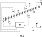
- FIG. 5 illustrates a schematic view of an exemplary sensor 10 in accordance with various embodiments described herein.
- the exemplary sensor 10 illustrated in FIG. 5 is configured such that the beam component 110 is configured to propagate the active optical beam in an emission direction towards a mobile reflection platform configured for movement relative to the beam component 110 such that the orientation of the beam path 120 may be selectively varied over time.
- a mobile reflection platform may be defined by a reflective element 140, such as, for example, a corner cube, that is secured relative to a mobile platform 141 (e.g., a UAV) configured to move relative to a stationary base platform and/or the one or more photodetectors 130.
- the beam path 120 defined by the optical beam is at least approximately oriented along a single axis defined between the beam component 110 and a reflective element 140, such as, for example, a corner cube, configured to reflect the optical beam back towards the beam component 110.
- each of the one or more photodetector 130 of the sensor 10 may be fixedly secured and/or spatially distributed within an environment such that the particulate data generated by the one or more photodetectors 130 may enable the sensor 10 to more accurately spatially resolve the particulate matter concentration within a sensing region 101 as the mobile platform 141 to which the reflective element 140 is secured is moved between one or more locations.
- the mobile platform 141 may be controlled such that the position of the reflective element is moved from a first position to a second position relative to the beam component 110.
- the beam component 110 may be configured such that the emission direction defined by the beam path 120 may be at least partially adjusted such that at least a portion of the beam path 120 is defined along an axis oriented between the beam component 110 and the second location of the reflective element 140.
- FIG. 2 illustrates a schematic view of an exemplary apparatus in accordance with various embodiments described herein.
- FIG. 2 illustrates a schematic view of a controller 200 of an exemplary sensor 10, in accordance with various embodiments of the present disclosure.
- an exemplary controller 200 may comprise a memory 201, a processor 202, input/output circuitry 203, communication circuitry 205, particulate matter detection circuitry 206, gas detection circuitry 207, and beam operation circuitry 204.
- the controller 200 may be configured to execute the operations described herein.
- the components are described with respect to functional limitations, it should be understood that the particular implementations necessarily include the use of particular hardware.
- circuitry as used herein with respect to components of the controller 200 should therefore be understood to include particular hardware configured to perform the functions associated with the particular circuitry as described herein.
- circuitry should be understood broadly to include hardware and, in some embodiments, software for configuring the hardware.
- circuitry may include processing circuitry, storage media, network interfaces, input/output devices, and the like.
- other elements of the controller 200 may provide or supplement the functionality of particular circuitry.
- the processor 202 may provide processing functionality
- the memory 201 may provide storage functionality
- the communications circuitry 205 may provide network interface functionality, and the like.
- the processor 202 (and/or co-processor or any other processing circuitry assisting or otherwise associated with the processor) may be in communication with the memory 201 via a bus for passing information among components of the apparatus.
- the memory 201 may be non-transitory and may include, for example, one or more volatile and/or non-volatile memories.
- the memory 201 may be an electronic storage device (e.g., a computer readable storage medium).
- the memory 201 may be configured to store information, data, content, applications, instructions, or the like, for enabling the apparatus to carry out various functions in accordance with example embodiments of the present disclosure.
- the memory 201 may be configured to store partially or wholly any electronic information, data, data structures, embodiments, examples, figures, processes, operations, techniques, algorithms, instructions, systems, apparatuses, methods, look-up tables, or computer program products described herein, or any combination thereof.
- the memory 201 may be configured to store timestamp data, location data, and/or the like, as well as gas data, such as, for example, at least a portion of a frequency-comb data stream, gas concentration data, gas property data, and/or the like associated with a volume of gas.
- the memory 201 may be configured to store particulate data, such as, for example, particulate size data, particulate type data, particulate shape data, particulate cross-sectional area data, particulate mass data, particulate matter concentration data, particulate quantity data and/or the like, associated with a volume of gas.
- particulate data such as, for example, particulate size data, particulate type data, particulate shape data, particulate cross-sectional area data, particulate mass data, particulate matter concentration data, particulate quantity data and/or the like, associated with a volume of gas.
- the processor 202 may be embodied in a number of different ways and may, for example, include one or more processing devices configured to perform independently. Additionally or alternatively, the processor may include one or more processors configured in tandem via a bus to enable independent execution of instructions, pipelining, and/or multithreading.
- processing circuitry may be understood to include a single core processor, a multi-core processor, multiple processors internal to the apparatus, and/or remote or "cloud" processors.
- the processor 202 may be configured to execute instructions stored in the memory 201 or otherwise accessible to the processor. Alternatively, or additionally, the processor may be configured to execute hard-coded functionality. As such, whether configured by hardware or software methods, or by a combination thereof, the processor may represent an entity (e.g., physically embodied in circuitry) capable of performing operations according to an embodiment of the present disclosure while configured accordingly. Alternatively, as another example, when the processor is embodied as an executor of software instructions, the instructions may specifically configure the processor to perform the algorithms and/or operations described herein when the instructions are executed.
- the controller 200 may include input-output circuitry 203 that may, in turn, be in communication with the processor 202 to provide output to the user and, in some embodiments, to receive input such as a command provided by the user.
- the input-output circuitry 203 may comprise a user interface, such as a graphical user interface (GUI), and may include a display that may include a web user interface, a GUI application, a mobile application, a client device, or any other suitable hardware or software.
- GUI graphical user interface
- the input-output circuitry 203 may also include a display device, a display screen, user input elements, such as a touch screen, touch areas, soft keys, a keyboard, a mouse, a microphone, a speaker (e.g., a buzzer), a light emitting device (e.g., a red light emitting diode (LED), a green LED, a blue LED, a white LED, an infrared (IR) LED, or a combination thereof), or other input-output mechanisms.
- a display device e.g., a display screen, user input elements, such as a touch screen, touch areas, soft keys, a keyboard, a mouse, a microphone, a speaker (e.g., a buzzer), a light emitting device (e.g., a red light emitting diode (LED), a green LED, a blue LED, a white LED, an infrared (IR) LED, or a combination thereof), or other input-output mechanisms.
- LED
- the processor 202, input-output circuitry 203 (which may utilize the processing circuitry), or both may be configured to control one or more functions of one or more user interface elements through computer-executable program code instructions (e.g., software, firmware) stored in a non-transitory computer-readable storage medium (e.g., memory 201).
- Input-output circuitry 203 is optional and, in some embodiments, the controller 200 may not include input-output circuitry.
- the controller 200 may generate user interface data for display by one or more other devices with which one or more users directly interact and transmit the generated user interface data to one or more of those devices.
- the controller 200, using user interface circuitry may generate user interface data for display by one or more display devices and transmit the generated user interface data to those display devices.
- the communications circuitry 205 may be a device or circuitry embodied in either hardware or a combination of hardware and software that is configured to receive and/or transmit data from/to a network and/or any other device, circuitry, or module in communication with the apparatus 200.
- the communications circuitry 205 may be configured to communicate with one or more computing devices via wired (e.g., USB) or wireless (e.g., Bluetooth, Wi-Fi, cellular, and/or the like) communication protocols.
- the communications circuitry 205 may be configured to facilitate communication between an exemplary fluid flow device and one or more computing devices of an exemplary fluid flow management system via wired (e.g., USB, ethernet, and/or the like) or wireless (e.g., Bluetooth, Wi-Fi, cellular, and/or the like) communication protocols, as described in further detail herein.
- wired e.g., USB, ethernet, and/or the like
- wireless e.g., Bluetooth, Wi-Fi, cellular, and/or the like
- the processor 202 may be configured to communicate with the particulate matter detection circuitry 206.
- the particulate matter detection circuitry 206 may be a device and/or circuitry embodied in either hardware or a combination of hardware and software that is configured to receive, process, generate, and/or transmit data (e.g., particulate data), such as a photodetector signal generated by a photodetector arranged within the sensor 10.
- the particulate matter detection circuitry 206 may be configured to detect the presence of particulate matter within the sensing region of the sensor 10 (e.g., at one or more locations along the beam path of the beam emitted from the beam component) based at least in part on the particulate data received from the one or more photodetectors of the sensor 10.
- the particulate matter detection circuitry 206 may be configured to determine a particulate matter concentration associated with detected particulate matter within a volume of gas based at least in part on the particulate data (e.g., a photodetector signal) received from one or more of the photodetectors of the sensor 10. For example, in various embodiments, the particulate matter detection circuitry 206 may determine a particulate matter concentration as defined by the one or more particulates detected by a photodetector based at least in part on the pulse quantity and/or a pulse intensity defined by the portion of the optical beam detected by the photodetector.
- the particulate matter detection circuitry 206 may determine a particulate matter concentration as defined by the one or more particulates detected by a photodetector based at least in part on the pulse quantity and/or a pulse intensity defined by the portion of the optical beam detected by the photodetector.
- the particulate matter detection circuitry 206 may be configured to execute a data processing operation wherein a photodetector signal received from the one or more photodetectors and defined at least in part by the particulate data generated by the one or more photodetectors is used together with a known optical pulse rate defined by an operation of the beam component (e.g., the light beam generator) in a phase-locked loop (PLL) to enhance the photodetector signal.
- the beam component e.g., the light beam generator
- PLL phase-locked loop
- particulate data generated by one or more photodetector of the sensor 10 may be received by the particulate matter detection circuitry 206 and processed with the optical pulse rate using a phase-locked loop to at least partially reduce and/or minimize the background noise within the photodetector signal captured by the photodetector.
- the processor 202 may be configured to communicate with the gas detection circuitry 207.
- the gas detection circuitry 207 may be a device or circuitry embodied in either hardware or a combination of hardware and software that is configured to receive, process, generate, and/or transmit data (e.g., gas data) associated with a gas sensing operation executed by the sensor 10.
- the gas detection circuitry 207 may be configured to receive gas data generated by a beam component of the sensor 10, such as, for example, a frequency-comb data stream that includes multiple wavelengths.
- the gas detection circuitry 207 may detect the presence of a specific gas within a sensing region based at least in part on the gas data generated by the beam component via an optical gas sensing means.
- the gas detection circuitry 207 may be configured to execute one or more instructions defining a dual-frequency-comb spectroscopy method of detecting one or more pre-designated gases within a sensing region.
- the gas detection circuitry 207 may be configured to determine a gas concentration associated with detected gas within a sensing region based at least in part on the gas data received from the beam component of the sensor 10. For example, in various embodiments, the gas detection circuitry 206 may determine a gas concentration of a specific gas based at least in part on an absorption intensity defined at specific wavelength defined within the known absorption band of the specific gas.
- the processor 202 may be configured to communicate with the beam operation circuitry 204.
- the beam operation circuitry 204 may be a device or circuitry embodied in either hardware or a combination of hardware and software that is configured to selectively control operation of the beam component (e.g., the light beam generator) of the sensor 10 as part of one or more gas and/or particulate matter sensing operations.
- the beam operation circuitry 204 may be configured to generate a control signal for transmission to the beam component that is configured to cause the beam component to emit an optical beam therefrom according to one or more predefined characteristics, such as, for example, a predetermined optical pulse rate.
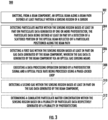
- FIG. 3 is an illustrative flowchart of various steps for an example method in accordance with various embodiments of the present disclosure.
- FIG. 3 a flowchart of an exemplary method 300 of detecting one or more gases and particulate matter within a sensor is provided.
- one or more operations of the illustrated exemplary method 300 may be executed by controlling a sensor in accordance with one or more example embodiments described herein.
- various operations discussed below with respect to exemplary method 300 may be carried out using various components of an exemplary sensor, such as, for example, an exemplary sensor 10 as described above in reference to FIGS. 1-2 .
- exemplary method 300 may include emitting, from a beam component, an optical beam along a beam path defined at least partially within a sensing region of a sensor.
- emitting the optical beam from the beam component may include pulsing the optical beam such that the optical beam defines an active optical beam defined at least in part by an optical pulse rate.
- particulate matter may be detected within the sensing region based at least in part on particulate data generated by one or more photodetector.
- the particulate data generated by the one or more photodetector may be defined at least in part by a detection of a scattered portion of the optical beam that reflects off a particulate positioned along the beam path.
- a scattered portion of the optical beam that reflects off a particulate positioned along the beam path adjacent (e.g., within a field of view of) a photodetector may be detected by the photodetector and, in response, particulate data associated with the particulate may be generated (e.g., by the photodetector) to facilitate a determination of one or more particulate characteristics (e.g., particulate size, particulate matter concentration, and/or the like) defined by the particulate.
- particulate characteristics e.g., particulate size, particulate matter concentration, and/or the like
- detecting the particulate matter within the sensing region may be defined at least in part by an operation of determining (e.g., via a controller) a particulate matter concentration associated with the particulate matter based at least in part on the particulate data.
- the particulate data may be transmitted by a photodetector to a controller configured to execute at least a portion of the particulate matter sensing operation steps described herein.
- a first gas may be detected within the sensing region based at least in part on gas data generated by the beam component.
- the gas data may be generated by the beam component via an optical gas sensing means.
- the gas data may be defined at least in part by a detected absorption (e.g., an absorption intensity) of at least a portion of the optical beam emitted from the beam component at a first wavelength corresponding to the first gas.
- dual-frequency-comb spectroscopy may be used to detect the presence of a first gas based at least in part on a portion of the generated gas data (e.g., a frequency-comb data stream including multiple wavelengths) defined at a first wavelength that is within the absorption band of the first gas.
- detecting the first gas may be defined at least in part by an operation of determining (e.g., via a controller) a gas concentration associated with the first gas based at least in part on the gas data.
- the gas data may be transmitted by a beam component to a controller configured to execute at least a portion of the gas sensing operation steps described herein.
- the gas data generated by the beam component may be further defined by an absorption intensity defined at the first wavelength.
- the gas concentration associated with the first gas may be determined based at least in part on the absorption intensity defined at least at the first wavelength, as measured by the beam component.
- an exemplary method 300 of detecting one or more gases and particulate matter within a sensor may further include executing a data processing operation wherein a photodetector signal defined at least in part by the particulate data generated by the one or more photodetectors is processed with the optical pulse rate using a phase-locked loop to enhance the photodetector signal by at least partially reducing signal noise.
- an exemplary method 300 of detecting one or more gases and particulate matter within a sensor may further include detecting a second gas within the sensing region based at least in part on gas data generated by the beam component.
- gas data generated by the beam component.
- dual-frequency-comb spectroscopy may be used to detect the presence of the second gas based at least in part on a portion of the generated gas data (e.g., the frequency-comb data stream including multiple wavelengths) defined at a second wavelength that is within the absorption band of the second gas.
- an exemplary method 300 of detecting one or more gases and particulate matter within a sensor may include determining a cumulative particulate matter concentration within the sensing region based on a plurality of particulate data respectively generated by a plurality of photodetectors. For example, respective particulate data generated by each of a plurality of photodetectors may be received (e.g., by a controller) from the plurality of photodetectors and used to determine the cumulative particulate matter concentration.
- the cumulative particulate matter concentration may be defined at least in part by a plurality of particulates positioned at respective locations within the sensing region (e.g., along respective portions of the beam path) that are detected by the photodetectors via a corresponding plurality of optical beam reflections captured by the photodetectors.
- a first scattered portion of the optical beam reflected off a first particulate positioned along the beam path adjacent (e.g., within a field of view of) a first photodetector may be detected by the first photodetector
- a second scattered portion of the optical beam reflected off a second particulate positioned along the beam path adjacent a second photodetector may be detected by the second photodetector
- a third scattered portion of the optical beam reflected off a third particulate positioned along the beam path adjacent a third photodetector may be detected by the third photodetector
- a fourth scattered portion of the optical beam reflected off a fourth particulate positioned along the beam path adjacent a fourth photodetector may be detected by the fourth photodetector.
- the first, second, third, and fourth photodetectors may respectively generate first, second, third, and fourth particulate data associated with the corresponding first, second, third, and fourth particulate adjacent thereto.
- the cumulative particulate matter concentration defined by the particulate matter within the sensing region (e.g., the first, second, third, and fourth particulates) a may be determined (e.g., by a controller) based in part on each of the first, second, third, and fourth particulate data generated by the respective photodetectors of the plurality.
- the particulate matter concentration along the beam path may be at least partially spatially resolved based at least in part on the first, second, third, and fourth particulate data generated by the plurality of photodetectors.
Landscapes
- Physics & Mathematics (AREA)
- Spectroscopy & Molecular Physics (AREA)
- General Physics & Mathematics (AREA)
- Chemical & Material Sciences (AREA)
- Life Sciences & Earth Sciences (AREA)
- Health & Medical Sciences (AREA)
- Analytical Chemistry (AREA)
- Biochemistry (AREA)
- General Health & Medical Sciences (AREA)
- Immunology (AREA)
- Pathology (AREA)
- Dispersion Chemistry (AREA)
- Engineering & Computer Science (AREA)
- Optics & Photonics (AREA)
- Combustion & Propulsion (AREA)
- Food Science & Technology (AREA)
- Medicinal Chemistry (AREA)
- Investigating Or Analysing Materials By Optical Means (AREA)
Applications Claiming Priority (1)
| Application Number | Priority Date | Filing Date | Title |
|---|---|---|---|
| US18/300,252 US20240344974A1 (en) | 2023-04-13 | 2023-04-13 | Apparatus and method for sensing gas and particulate matter using an optical beam |
Publications (2)
| Publication Number | Publication Date |
|---|---|
| EP4446729A2 true EP4446729A2 (de) | 2024-10-16 |
| EP4446729A3 EP4446729A3 (de) | 2024-12-25 |
Family
ID=90236223
Family Applications (1)
| Application Number | Title | Priority Date | Filing Date |
|---|---|---|---|
| EP24162870.0A Pending EP4446729A3 (de) | 2023-04-13 | 2024-03-12 | Vorrichtung und verfahren zur messung von gas und partikeln unter verwendung eines optischen strahls |
Country Status (4)
| Country | Link |
|---|---|
| US (1) | US20240344974A1 (de) |
| EP (1) | EP4446729A3 (de) |
| JP (1) | JP2024152634A (de) |
| CN (1) | CN118858170A (de) |
Families Citing this family (1)
| Publication number | Priority date | Publication date | Assignee | Title |
|---|---|---|---|---|
| CN121783798A (zh) * | 2026-03-03 | 2026-04-03 | 北京英视睿达科技股份有限公司 | 基于光散射进行颗粒物浓度检测的方法及系统 |
Family Cites Families (23)
| Publication number | Priority date | Publication date | Assignee | Title |
|---|---|---|---|---|
| US5392114A (en) * | 1988-03-30 | 1995-02-21 | Cole; Martin T. | Fluid pollution monitor |
| DE19720007C2 (de) * | 1997-05-13 | 1999-06-02 | Siemens Ag | Gassensorsystem zur Detektion von mindestens einem Gas oder von Partikeln oder einer Kombination daraus mit zwei Gassensoren, Verfahren zu dessen Betrieb und Verwendung des Gassensorsystems |
| ES2315262T3 (es) * | 2001-08-17 | 2009-04-01 | Mcdermott Technology, Inc. | Detector de humos de dispersion de luz. |
| CA2965635C (en) * | 2004-11-12 | 2020-07-21 | Xtralis Technologies Ltd | Particle detector, system and method |
| NO326482B1 (no) * | 2005-05-31 | 2008-12-15 | Integrated Optoelectronics As | En ny infrarod laserbasert alarm |
| JP4227991B2 (ja) * | 2005-12-28 | 2009-02-18 | トヨタ自動車株式会社 | 排ガス分析装置および排ガス分析方法 |
| DE102006011565B4 (de) * | 2006-03-10 | 2008-01-31 | Eads Deutschland Gmbh | Gassensorsystem |
| JP2009229414A (ja) * | 2008-03-25 | 2009-10-08 | Osaka Gas Co Ltd | 検知装置 |
| US9377481B1 (en) * | 2010-06-16 | 2016-06-28 | The United States Of America As Represented By The Administrator Of National Aeronautics And Space Administration | Multi-parameter scattering sensor and methods |
| JPWO2015045266A1 (ja) * | 2013-09-24 | 2017-03-09 | 国立大学法人東京農工大学 | 測定装置 |
| US9915600B2 (en) * | 2016-02-19 | 2018-03-13 | Research Triangle Institute | Devices, systems and methods for detecting particles |
| WO2016154054A1 (en) * | 2015-03-20 | 2016-09-29 | SMS Sensors Incorporated | Systems and methods detecting gases, airborne compounds and other particulates |
| US11506953B2 (en) * | 2015-11-13 | 2022-11-22 | Halliburton Energy Services, Inc. | Downhole telemetry system using frequency combs |
| EP3176564A1 (de) * | 2015-12-03 | 2017-06-07 | Fuji Electric Co., Ltd. | Gasanalysevorrichtung vom lasertyp |
| US10801940B2 (en) * | 2017-06-02 | 2020-10-13 | Airviz Inc. | Low energy ultrafine particle detector |
| US11320411B2 (en) * | 2018-03-09 | 2022-05-03 | Government Of The United States As Represented By The Administrator Of The U.S. Environmental Protection Agency | Air pollution sensor to measure major carbon components in the environment |
| US20220136950A1 (en) * | 2019-04-09 | 2022-05-05 | Colorado State University Research Foundation | Portable atmospheric monitor |
| US11237095B2 (en) * | 2019-04-25 | 2022-02-01 | Particle Measuring Systems, Inc. | Particle detection systems and methods for on-axis particle detection and/or differential detection |
| US11112310B2 (en) * | 2019-08-29 | 2021-09-07 | Dublin City University | Dual-comb spectroscopy |
| US11686622B2 (en) * | 2019-09-16 | 2023-06-27 | The Regents Of The University Of Colorado, A Body Corporate | Systems and methods for dual comb spectroscopy |
| CN114729885A (zh) * | 2019-11-22 | 2022-07-08 | ams有限公司 | 基于光学的颗粒物感测 |
| US12140523B2 (en) * | 2021-12-15 | 2024-11-12 | Samsung Electronics Co., Ltd. | Optical measurement apparatus and optical measurement method |
| US20230280270A1 (en) * | 2022-03-07 | 2023-09-07 | University Of South Carolina | Spectroscopy Combining Base Stations and Unmanned Aerial Vehicles |
-
2023
- 2023-04-13 US US18/300,252 patent/US20240344974A1/en active Pending
-
2024
- 2024-03-12 EP EP24162870.0A patent/EP4446729A3/de active Pending
- 2024-03-21 JP JP2024045232A patent/JP2024152634A/ja active Pending
- 2024-03-25 CN CN202410340658.0A patent/CN118858170A/zh active Pending
Also Published As
| Publication number | Publication date |
|---|---|
| JP2024152634A (ja) | 2024-10-25 |
| CN118858170A (zh) | 2024-10-29 |
| US20240344974A1 (en) | 2024-10-17 |
| EP4446729A3 (de) | 2024-12-25 |
Similar Documents
| Publication | Publication Date | Title |
|---|---|---|
| US7292338B2 (en) | Particle detection apparatus and particle detection method used therefor | |
| RU2737362C2 (ru) | Система и способ лазерного детектирования | |
| JP2022058585A (ja) | マルチパスサンプルセル | |
| EP3339843B1 (de) | Raman-spektrum-inspektionsvorrichtung und sicherheitsüberwachungsverfahren für eine raman-spektrum-inspektionsvorrichtung | |
| CN105891075B (zh) | 一种多点协同激光模组及气体检测系统 | |
| CN110300884A (zh) | 光学颗粒传感器模块 | |
| US9671325B2 (en) | Particle measuring device | |
| US20240344974A1 (en) | Apparatus and method for sensing gas and particulate matter using an optical beam | |
| EP3531111A1 (de) | Auf bildgraustufenerkennung basierender raman-spektrum-detektor und verfahren | |
| EP3505915B1 (de) | Raman-spektrum-detektionsvorrichtung und -verfahren basierend auf der stärke reflektierten lichts und bilderkennung | |
| CN118591720A (zh) | 便携式光谱仪设备 | |
| EP4336162A1 (de) | Multidirektionales detektorsystem mit offenem weg und verfahren zur verwendung davon | |
| JP2013542441A (ja) | ナノ粒子検出器 | |
| CN114609687A (zh) | 用于检测透明物体的光电传感器及透明物体的检测方法 | |
| US20190195804A1 (en) | Raman spectrum detection apparatus and method based on power of reflected light | |
| CN109520901A (zh) | 一种基于激光前散射法的双光路不平衡性测量装置 | |
| TW202043729A (zh) | 能見度儀、能見度量測方法和路燈裝置及其操作方法 | |
| CN109342394A (zh) | 一种采用双波长激光的手持式拉曼光谱仪及实现方法 | |
| CN106932340B (zh) | 基于积分球的光检测系统 | |
| CA3033493A1 (en) | Skinprint analysis method and apparatus | |
| CN208488174U (zh) | 基于图像识别的拉曼光谱检测设备 | |
| TW201621295A (zh) | 顆粒計數器 | |
| CN223727618U (zh) | 一种颗粒物检测装置、空气检测装置及净化设备 | |
| CN115420691B (zh) | 遥测收发装置的校正系统、方法、装置、设备及存储介质 | |
| CN209327204U (zh) | 一种基于长光程红外吸收法的co监测仪 |
Legal Events
| Date | Code | Title | Description |
|---|---|---|---|
| PUAI | Public reference made under article 153(3) epc to a published international application that has entered the european phase |
Free format text: ORIGINAL CODE: 0009012 |
|
| STAA | Information on the status of an ep patent application or granted ep patent |
Free format text: STATUS: REQUEST FOR EXAMINATION WAS MADE |
|
| 17P | Request for examination filed |
Effective date: 20240312 |
|
| AK | Designated contracting states |
Kind code of ref document: A2 Designated state(s): AL AT BE BG CH CY CZ DE DK EE ES FI FR GB GR HR HU IE IS IT LI LT LU LV MC ME MK MT NL NO PL PT RO RS SE SI SK SM TR |
|
| PUAL | Search report despatched |
Free format text: ORIGINAL CODE: 0009013 |
|
| AK | Designated contracting states |
Kind code of ref document: A3 Designated state(s): AL AT BE BG CH CY CZ DE DK EE ES FI FR GB GR HR HU IE IS IT LI LT LU LV MC ME MK MT NL NO PL PT RO RS SE SI SK SM TR |
|
| RIC1 | Information provided on ipc code assigned before grant |
Ipc: G01N 21/53 20060101ALI20241119BHEP Ipc: G01N 21/39 20060101AFI20241119BHEP |