EP4446235A1 - Aéronef comportant une canalisation d'apport de dihydrogène logée dans un couloir délimité entre deux longerons d'une aile - Google Patents
Aéronef comportant une canalisation d'apport de dihydrogène logée dans un couloir délimité entre deux longerons d'une aile Download PDFInfo
- Publication number
- EP4446235A1 EP4446235A1 EP24169587.3A EP24169587A EP4446235A1 EP 4446235 A1 EP4446235 A1 EP 4446235A1 EP 24169587 A EP24169587 A EP 24169587A EP 4446235 A1 EP4446235 A1 EP 4446235A1
- Authority
- EP
- European Patent Office
- Prior art keywords
- wing
- aircraft
- spar
- corridor
- engine
- Prior art date
- Legal status (The legal status is an assumption and is not a legal conclusion. Google has not performed a legal analysis and makes no representation as to the accuracy of the status listed.)
- Pending
Links
Images

Classifications
-
- B—PERFORMING OPERATIONS; TRANSPORTING
- B64—AIRCRAFT; AVIATION; COSMONAUTICS
- B64D—EQUIPMENT FOR FITTING IN OR TO AIRCRAFT; FLIGHT SUITS; PARACHUTES; ARRANGEMENT OR MOUNTING OF POWER PLANTS OR PROPULSION TRANSMISSIONS IN AIRCRAFT
- B64D37/00—Arrangements in connection with fuel supply for power plant
- B64D37/30—Fuel systems for specific fuels
-
- B—PERFORMING OPERATIONS; TRANSPORTING
- B64—AIRCRAFT; AVIATION; COSMONAUTICS
- B64D—EQUIPMENT FOR FITTING IN OR TO AIRCRAFT; FLIGHT SUITS; PARACHUTES; ARRANGEMENT OR MOUNTING OF POWER PLANTS OR PROPULSION TRANSMISSIONS IN AIRCRAFT
- B64D27/00—Arrangement or mounting of power plants in aircraft; Aircraft characterised by the type or position of power plants
- B64D27/02—Aircraft characterised by the type or position of power plants
- B64D27/10—Aircraft characterised by the type or position of power plants of gas-turbine type
- B64D27/12—Aircraft characterised by the type or position of power plants of gas-turbine type within, or attached to, wings
-
- B—PERFORMING OPERATIONS; TRANSPORTING
- B64—AIRCRAFT; AVIATION; COSMONAUTICS
- B64D—EQUIPMENT FOR FITTING IN OR TO AIRCRAFT; FLIGHT SUITS; PARACHUTES; ARRANGEMENT OR MOUNTING OF POWER PLANTS OR PROPULSION TRANSMISSIONS IN AIRCRAFT
- B64D37/00—Arrangements in connection with fuel supply for power plant
- B64D37/005—Accessories not provided for in the groups B64D37/02 - B64D37/28
-
- B—PERFORMING OPERATIONS; TRANSPORTING
- B64—AIRCRAFT; AVIATION; COSMONAUTICS
- B64C—AEROPLANES; HELICOPTERS
- B64C3/00—Wings
- B64C3/18—Spars; Ribs; Stringers
- B64C3/182—Stringers, longerons
-
- B—PERFORMING OPERATIONS; TRANSPORTING
- B64—AIRCRAFT; AVIATION; COSMONAUTICS
- B64C—AEROPLANES; HELICOPTERS
- B64C3/00—Wings
- B64C3/18—Spars; Ribs; Stringers
- B64C3/185—Spars
Definitions
- the present invention relates to the field of aircraft and, in particular, to aircraft whose energy source is liquid or gaseous dihydrogen to supply a combustion chamber of an engine.
- the present invention thus relates to an aircraft comprising a dihydrogen supply pipe housed in a corridor delimited between two spars of a wing of the aircraft.
- dihydrogen As an energy source in some vehicles. Dihydrogen could therefore be used as an energy source in an aircraft.
- the dihydrogen is stored in a tank and a supply line ensures the transport of the dihydrogen from the tank to the combustion chamber of an engine.
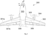
- FIG. 3 shows a prior art aircraft 300 which comprises a wing 302 on each side of a fuselage 303 and under each wing 302 is fixed at least one engine 304 operating on dihydrogen.
- the aircraft 300 comprises a dihydrogen tank 308 and a supply line 306 which supplies dihydrogen to each engine 304 from the tank 308.
- Each wing 302 has a front spar 301a and a rear spar 301b, as well as a lower surface wall and an upper surface wall fixed below and above the spars 301a-b. Also fixed in an articulated manner to the rear spar 301b are the movable elements of the wing 302 such as the ailerons as well as the actuators of these movable elements.
- the engine 304 comprises a compressor and a turbine 305, upstream and downstream of the combustion chamber of the engine 304.
- pieces, in particular pieces of the blades of the compressor and/or the turbine 305 may separate from the rotating shaft on which they are fixed, with the risk of colliding with a supply pipe 306.
- the document FR3127203 describes an aircraft comprising a propulsion system, at least one pipe for transporting dihydrogen from a dihydrogen tank to the propulsion system and a channel for burying this transport pipe.
- the transport pipe is arranged between a front spar and a rear spar of the wing, i.e. in a wing box. This transport pipe is however not protected from possible debris coming from the propulsion system.
- An object of the present invention is to propose an aircraft comprising a dihydrogen supply pipe housed in a corridor delimited between two spars of a wing of the aircraft.
- the intake duct is protected from possible debris coming from the engine.
- the intake duct being arranged in the corridor between said first and second rear spars, is also arranged outside the path of potential debris coming from the engine.
- each wing has at a lower surface skin at least one low window that opens the corridor through said lower surface skin, and at a higher surface skin at least one high window that opens the corridor through said higher surface skin.
- the high window is on the side of a proximal end of the wing and the low window is on the side of a distal end of the wing.
- the high window is on the side of a distal end of the wing and the low window is on the side of a proximal end of the wing.
- the aircraft comprises, for each corridor, a fan arranged in said corridor.
- the aircraft comprises between the intake pipe and the second rear spar, a protective wall made of a thermally insulating material.
- each of the front spars and the first and second rear spars extends generally over the entire length of the wing.
- the distance between the first rear spar and the second rear spar, between a leading edge and a trailing edge of the wing, is less than the distance between the first rear spar and the front spar.
- FIG. 1 shows an aircraft 100 which has a fuselage 103 on either side of which is fixed a wing 102 which conventionally has at the front a leading edge 101a and at the rear a trailing edge 101b. Under each wing 102 is fixed at least one engine 104. In the embodiment of the invention presented in the Fig. 1 , each engine 104 is fixed at the leading edge 101a of the wing 102.
- X is called the longitudinal direction of the aircraft 100
- Y the transverse direction of the aircraft 100 which is horizontal when the aircraft is on the ground
- Z the vertical direction or vertical height when the aircraft is on the ground
- front and rear are to be considered in relation to a direction of advancement of the aircraft 100 during operation of the engines 104, this direction being represented schematically by the arrow 107.
- each engine 104 takes the form of a turbojet with a combustion chamber supplied with dihydrogen as fuel.
- the engine 104 also comprises at least one rotor 104a rotatable about an axis of rotation X' substantially parallel to the longitudinal direction X.
- substantially parallel is meant that the axis of rotation X' is parallel to the direction longitudinal direction X to within a few degrees, these degrees corresponding to the usual tolerances for manufacturing and installing the rotor.
- the axis of the rotor 104 may extend along an axis having an inclination in the XY plane of between -5° and +5° relative to the longitudinal direction X, and more precisely between -1° and +1° relative to the longitudinal direction X, and along an axis having an inclination in the XZ plane of between -10° and +10° relative to the longitudinal direction X, and more precisely between -5° and +5° relative to the longitudinal direction X.
- the rotor 104a may be a compressor and/or a turbine which consist of blades fixed on a disk rotating around said axis of rotation X'.
- compressor and turbine 104a are upstream and downstream of the combustion chamber of the engine 104.
- the aircraft 100 also comprises a dihydrogen tank 108 which is arranged here at the level of a central part of the fuselage 103, but which could be arranged in another part of the aircraft 100.
- the dihydrogen can be liquid or gaseous.
- the aircraft 100 comprises, for each engine 104, a supply pipe 106 fluidically connected between the engine 104 and the tank 108.
- the Fig. 2 shows a section of the wing 102 which has a lower surface wall 202a and an upper surface wall 202b and between them, a front spar 102a extending along the wing 102 and arranged at a forward portion of the wing 102 just behind the leading edge 101a.
- the front spar 102a is generally arranged at a distance of between 10% and 25% of the distance between the leading edge 101a and the trailing edge 101b (i.e. of the chord of the wing 102), from the leading edge 101a.
- the wing 102 also has, between the intrados wall 202a and the extrados wall 202b, a first rear spar 102b extending to the rear of the front spar 102a and a second rear spar 102c extending to the rear of the first rear spar 102b.
- the first rear spar 102b is generally arranged at a distance of between 50% and 70% of the distance between the leading edge 101a and the trailing edge 101b, from the leading edge 101a.
- the second rear spar 102c is generally arranged at a distance of between 60% and 75% of the distance between the leading edge 101a and the trailing edge 101b, from the leading edge 101a.
- the distance between the first rear spar 102b and the second rear spar 102c is between 5% and 10% of the chord of the wing 102.
- the first rear spar 102b is thus closer to the second rear spar 102c than to the front spar 102a, in the direction leading edge 101a - trailing edge 101b of the wing 102 (i.e. along the chord of the wing 102).
- the distance between the first rear spar 102b and the second rear spar 102c is at least five times less than the distance between the first rear spar 102b and the front spar 102a.
- the first rear spar 102b is therefore arranged asymmetrically (i.e. non-centrally) between the front spar 102a and the second rear spar 102c.
- a box is thus defined between the front spar 102a and the first rear spar 102b, while a corridor is defined between the first and second rear spars 102b-c.
- Each spar 102a-c extends generally along the transverse direction Y. In other words, each spar 102a-c extends generally over the entire length of the wing 102 between the root of the wing 102 at the fuselage 103 and the end of the wing 102 furthest from the fuselage 103 (corresponding to the wing tip 102).
- the two rear spars 102b-c are generally parallel and define between them a corridor 110 which therefore runs in the wing 102 between the two rear spars 102b-c and between the intrados wall 202a and the extrados wall 202b.
- the volume defined between the front spar 102a and the first rear spar 102b corresponds to a wing box, which represents a much larger volume (for example five times larger) than the volume of the corridor 110 defined between the two rear spars 102b-c.
- the corridor 110 is therefore distinct from a wing box.
- Each spar 102a-c extends vertically between the intrados wall 202a and the extrados wall 202b.
- each supply pipe 106 extends rearward from the associated engine 104, that is to say here generally from the leading edge 101a, so as to join the inside of the corridor 110 of the wing 102 supporting said engine 104.
- the supply pipe 106 joins the corridor 110 as close as possible to limit the portion of the supply pipe 106 which could be intercepted by debris.
- the supply line 106 then runs inside the corridor 110 where it is protected to join the fuselage 103 and the tank 108.
- the movable elements 115 of the wing 102 are hingedly attached to the second rear spar 102c.
- the presence of the second spar 102c in particular allows the movable elements 115 of the wing 102 to be attached, this installation not being possible on the first rear spar 102b due to the presence of the supply pipe 106.
- the movable elements 115 of the wing 102 are here attached to the second spar 102c.
- each supply pipe 106 therefore extends very little outside a corridor 110 and when it is in a corridor 110, a supply pipe 106 is protected by the rear spars 102b-c which are relatively solid structural elements capable of deflecting any debris. More precisely, the supply pipe 106, by its location between the rear spars 102b-c, and in particular behind the first rear spar 102b, is outside the volume corresponding to the field of debris coming from a blade or a disk of said rotor 104a, and is therefore protected from the potential impact of such debris.
- each wing 102 has at the level of the intrados skin 202a, at least one low window 112a which opens the aisle 110 through said intrados skin 202a in order to communicate with the exterior of the aircraft 100, and at the level of the extrados skin 202b, at least one high window 112b which opens the aisle 110 through said extrados skin 202b in order to communicate with the exterior of the aircraft 100.
- the high 112b and low 112a windows are for example NACA air intakes.
- an air current is created between said at least one high window 112b and said at least one low window 112a, which makes it possible to evacuate the dihydrogen in the event of a leak from the supply pipe 106 in the corridor 110. More precisely, in flight of the aircraft 100, the pressure difference created by the wing 102 will force the passage of outside air into the corridor 110 by entering through the low window 112a and exiting through the high window 112b.
- Such a distribution allows in flight to ensure the circulation of air in the corridor 110 due to the pressure difference between the intrados and the extrados of the wing 102.
- At least one fan 116 is installed in each aisle 110.
- each wing 102 has a proximal end fixed to the fuselage 103 and, opposite, a distal end.
- the high window 112b which is on the side of the proximal end of the wing 102 and a low window 112a which is on the side of the distal end of the wing 102.
- the high window 112b could be on the side of the distal end of the wing and the low window 112a could be on the side of the proximal end of the wing.
- the proximal end, respectively distal, of the wing 102 is positioned higher (in the vertical direction Z) than the distal end, respectively proximal, of the wing 102.
- the dihedral of the wing 102 when the dihedral of the wing 102 is negative (i.e. the distal end lower in the vertical direction Z than the proximal end), the high window 112b is arranged at the proximal end, while the low window 112a is arranged at the distal end.
- the dihedral of the wing 102 is positive (i.e. the proximal end lower in the vertical direction Z than the distal end)
- the low window 112a is arranged at the proximal end
- the high window 112b is arranged at the distal end.
- the upper 112b and lower 112a windows may be arranged at the same location of the wing 102, for example at the same distance from the YZ plane which corresponds to the plane of symmetry of the aircraft 100.
- the upper 112b and lower 112a windows are arranged at different locations of the wing 102, in particular at different distances from the YZ plane.
- the low window 112a may be arranged at the lowest point (in the vertical direction Z) of the wing (in flight), while the high window 112b may be arranged at the highest point of the wing 102.
- the high 112b and low 112a windows are arranged so as to maximize the pressure difference between the air entering and leaving the corridor 110.
- a protective wall 204 made of a thermally insulating material is arranged between the supply pipe 106 and the second rear spar 102c.
- a thermally insulating material is for example, in a non-limiting manner, a closed-cell foam, or glass wool, or rock wool, or a product based on cork or glass micro-beads.
- the thermally insulating material may be a foam of polyimide, or a pressed silica fabric cured at 65°C, or a foam with an expanded polystyrene core with a metallized plastic coating, or a ceramic fiber based on alumina (Al2O3), silica (SiO2) and boron trioxide (B2O3).
Landscapes
- Engineering & Computer Science (AREA)
- Aviation & Aerospace Engineering (AREA)
- Structures Of Non-Positive Displacement Pumps (AREA)
Abstract
L'invention concerne un aéronef comportant une aile (102), un moteur fonctionnant au dihydrogène, une canalisation d'apport (106) pour le dihydrogène, où chaque aile (102) présente un longeron avant (102a), un premier longeron arrière (102b) s'étendant à l'arrière du longeron avant (102a) et un deuxième longeron arrière (102c) s'étendant à l'arrière du premier longeron arrière (102b), où les deux longerons arrière (102b-c) définissent entre eux, un couloir (110), et où chaque canalisation d'apport (106) s'étend vers l'arrière depuis le moteur associé puis à l'intérieur du couloir (110) de l'aile (102) supportant le moteur associé. Avec un tel arrangement, la canalisation d'apport est protégée d'éventuels débris venant du moteur.
Description
- La présente invention se rapporte au domaine des aéronefs et, en particulier, des aéronefs dont la source d'énergie est du dihydrogène liquide ou gazeux pour alimenter une chambre de combustion d'un moteur. La présente invention concerne ainsi un aéronef comportant une canalisation d'apport de dihydrogène logée dans un couloir délimité entre deux longerons d'une aile de l'aéronef.
- Il est connu d'utiliser le dihydrogène comme source d'énergie dans certains véhicules. Le dihydrogène pourrait donc être utilisé comme source d'énergie dans un aéronef. Le dihydrogène est stocké dans un réservoir et une canalisation d'apport assure le transport du dihydrogène du réservoir vers la chambre de combustion d'un moteur.
- La
Fig. 3 montre un aéronef 300 de l'état de la technique qui comporte une aile 302 de chaque côté d'un fuselage 303 et sous chaque aile 302 est fixé au moins un moteur 304 fonctionnant au dihydrogène. L'aéronef 300 comporte un réservoir de dihydrogène 308 et une canalisation d'apport 306 qui apporte du dihydrogène à chaque moteur 304 depuis le réservoir 308. - Chaque aile 302 présente un longeron avant 301a et un longeron arrière 301b, ainsi qu'une paroi d'intrados et une paroi d'extrados fixées au-dessous et au-dessus des longerons 301a-b. Au longeron arrière 301b, sont également fixés de manière articulée, les éléments mobiles de l'aile 302 tels que les ailerons ainsi que les actionneurs de ces éléments mobiles.
- Le moteur 304 comporte un compresseur et une turbine 305, en amont et en aval de la chambre de combustion du moteur 304. En cas d'avaries sur le moteur 304, des morceaux, en particulier des morceaux des pales du compresseur et/ou de la turbine 305 peuvent se séparer de l'arbre tournant sur lequel, ils sont fixés, au risque d'entrer en collision avec une canalisation d'apport 306.
- Il est donc souhaitable de prévoir un arrangement qui assure que la canalisation d'apport est protégée des éventuels débris provenant du compresseur et/ou de la turbine.
- Le document
FR3127203 - Un objet de la présente invention est de proposer un aéronef comportant une canalisation d'apport de dihydrogène logée dans un couloir délimité entre deux longerons d'une aile de l'aéronef.
- À cet effet, est proposé un aéronef comportant :
- au moins une aile,
- un réservoir de dihydrogène,
- pour chaque aile, au moins un moteur fonctionnant au dihydrogène, fixé à l'aile et comportant un rotor, et
- pour chaque moteur, une canalisation d'apport fluidiquement connectée entre le moteur et le réservoir de dihydrogène,
- où chaque aile présente un longeron avant s'étendant au niveau d'une partie avant de l'aile et un premier longeron arrière s'étendant à l'arrière du longeron avant et un deuxième longeron arrière s'étendant à l'arrière du premier longeron arrière, où les deux longerons arrière définissent entre eux, un couloir, et
- où chaque canalisation d'apport s'étend vers l'arrière depuis le moteur associé puis à l'intérieur du couloir de l'aile supportant le moteur associé.
- Avec un tel arrangement, la canalisation d'apport est protégée d'éventuels débris venant du moteur. En particulier, comme les premier et deuxième longerons arrière sont agencés en dehors d'une trajectoire de potentiels débris venant du moteur, la canalisation d'apport, étant agencée dans le couloir entre lesdits premier et deuxième longerons arrière, est également agencée en dehors de la trajectoire de potentiels débris venant du moteur.
- Avantageusement, chaque aile présente au niveau d'une peau d'intrados, au moins une fenêtre basse qui ouvre le couloir à travers ladite peau d'intrados, et au niveau d'une peau d'extrados, au moins une fenêtre haute qui ouvre le couloir à travers ladite peau d'extrados. Avantageusement, la fenêtre haute est du côté d'une extrémité proximale de l'aile et la fenêtre basse est du côté d'une extrémité distale de l'aile.
- Avantageusement, la fenêtre haute est du côté d'une extrémité distale de l'aile et la fenêtre basse est du côté d'une extrémité proximale de l'aile.
- Avantageusement, l'aéronef comporte pour chaque couloir, un ventilateur arrangé dans ledit couloir.
- Avantageusement, l'aéronef comporte entre la canalisation d'apport et le deuxième longeron arrière, une paroi de protection constituée d'un matériau thermiquement isolant. Avantageusement, chacun des longerons avant et des premier et deuxième longerons arrière s'étend globalement sur toute la longueur de l'aile.
- Avantageusement, la distance entre le premier longeron arrière et le deuxième longeron arrière, entre un bord d'attaque et un bord de fuite de l'aile, est inférieure à la distance entre le premier longeron arrière et le longeron avant.
- Les caractéristiques de l'invention mentionnées ci-dessus, ainsi que d'autres, apparaîtront plus clairement à la lecture de la description suivante d'un exemple de réalisation, ladite description étant faite en relation avec les dessins joints, parmi lesquels :
-
Fig. 1 est une vue de dessus d'un aéronef selon l'invention, -
Fig. 2 est une vue en coupe d'une aile de l'aéronef de laFig. 1 selon la ligne II-II, et -
Fig. 3 est une vue de dessus d'un aéronef de l'état de la technique. - La
Fig. 1 montre un aéronef 100 qui présente un fuselage 103 de part et d'autre duquel est fixée une aile 102 qui présente classiquement à l'avant un bord d'attaque 101a et à l'arrière un bord de fuite 101b. Sous chaque aile 102 est fixé au moins un moteur 104. Dans le mode de réalisation de l'invention présenté à laFig. 1 , chaque moteur 104 est fixé au niveau du bord d'attaque 101a de l'aile 102. - Par convention, on appelle X la direction longitudinale de l'aéronef 100, Y la direction transversale de l'aéronef 100 qui est horizontale lorsque l'aéronef est au sol, et Z la direction verticale ou hauteur verticale lorsque l'aéronef est au sol, ces trois directions X, Y et Z étant orthogonales entre elles.
- D'autre part, les termes " avant " et " arrière " sont à considérer par rapport à une direction d'avancement de l'aéronef 100 lors du fonctionnement des moteurs 104, cette direction étant représentée schématiquement par la flèche 107.
- Dans le mode de réalisation de l'invention présenté ici, chaque moteur 104 prend la forme d'un turboréacteur avec une chambre de combustion alimentée en dihydrogène comme carburant. Le moteur 104 comprend également au moins un rotor 104a mobile en rotation autour d'un axe de rotation X' sensiblement parallèle à la direction longitudinale X. Par "sensiblement parallèle", on entend que l'axe de rotation X' est parallèle à la direction longitudinale X à quelques degrés près, ces degrés correspondant aux tolérances usuelles de fabrication et d'installation du rotor. Par exemple, de façon non limitative, l'axe du rotor 104 peut s'étendre selon un axe ayant une inclinaison dans le plan XY comprise entre -5° et +5° par rapport à la direction longitudinale X, et plus précisément comprise entre -1° et +1° par rapport à la direction longitudinale X, et selon un axe ayant une inclinaison dans le plan XZ comprise entre -10° et +10° par rapport à la direction longitudinale X, et plus précisément comprise entre -5° et +5° par rapport à la direction longitudinale X. Le rotor 104a peut être un compresseur et/ou une turbine qui sont constitués de pales fixées sur un disque tournant autour dudit axe de rotation X'.
- Classiquement le compresseur et la turbine 104a sont en amont et en aval de la chambre de combustion du moteur 104.
- Du fait du mouvement de rotation du rotor 104a d'un moteur 104, un débris venant d'une pale ou d'un disque dudit rotor 104a va statistiquement se trouver dans un volume délimité par deux droites D1 et D2 qui tournent autour et qui se croisent au niveau de l'axe de rotation X' du moteur 104 et où chacun présente un angle par rapport audit axe de rotation X'. L'aéronef 100 comporte également un réservoir de dihydrogène 108 qui est disposé ici au niveau d'une partie centrale du fuselage 103, mais qui pourrait être disposé dans une autre partie de l'aéronef 100. Le dihydrogène peut être liquide ou gazeux.
- Pour transporter le dihydrogène, l'aéronef 100 comporte pour chaque moteur 104, une canalisation d'apport 106 fluidiquement connectée entre le moteur 104 et le réservoir 108. La
Fig. 2 montre une coupe de l'aile 102 qui présente une paroi d'intrados 202a et une paroi d'extrados 202b et entre elles, un longeron avant 102a s'étendant le long de l'aile 102 et disposé au niveau d'une partie avant de l'aile 102 juste derrière le bord d'attaque 101a. Le longeron avant 102a est généralement agencé à une distance comprise entre 10% et 25% de la distance entre le bord d'attaque 101a et le bord de fuite 101b (i.e. de la corde de l'aile 102), à partir du bord d'attaque 101a. - L'aile 102 présente également, entre la paroi d'intrados 202a et la paroi d'extrados 202b, un premier longeron arrière 102b s'étendant à l'arrière du longeron avant 102a et un deuxième longeron arrière 102c s'étendant à l'arrière du premier longeron arrière 102b. Le premier longeron arrière 102b est généralement agencé à une distance comprise entre 50% et 70% de la distance entre le bord d'attaque 101a et le bord de fuite 101b, à partir du bord d'attaque 101a. Le deuxième longeron arrière 102c est généralement agencé à une distance comprise entre 60% et 75% de la distance entre le bord d'attaque 101a et le bord de fuite 101b, à partir du bord d'attaque 101a. La distance entre le premier longeron arrière 102b et le deuxième longeron arrière 102c est comprise entre 5% et 10% de la corde de l'aile 102. Le premier longeron arrière 102b est ainsi plus proche du deuxième longeron arrière 102c que du longeron avant 102a, dans le sens bord d'attaque 101a - bord de fuite 101b de l'aile 102 (i.e. le long de la corde de l'aile 102). La distance entre le premier longeron arrière 102b et le deuxième longeron arrière 102c est au moins cinq fois inférieure à la distance entre le premier longeron arrière 102b et le longeron avant 102a. Le premier longeron arrière 102b est donc agencé de manière dissymétrique (i.e. non centrale) entre le longeron avant 102a et le deuxième longeron arrière 102c. Un caisson est donc défini entre le longeron avant 102a et le premier longeron arrière 102b, tandis qu'un couloir est défini entre les premier et deuxième longerons arrière 102b-c.
- Chaque longeron 102a-c s'étend globalement le long de la direction transversale Y. Autrement dit, chaque longeron 102a-c s'étend globalement sur toute la longueur de l'aile 102 entre l'emplanture de l'aile 102 au niveau du fuselage 103 et l'extrémité de l'aile 102 la plus éloignée du fuselage 103 (correspondant au saumon de l'aile 102).
- Les deux longerons arrière 102b-c sont globalement parallèles et définissent entre eux, un couloir 110 qui courre donc dans l'aile 102 entre les deux longerons arrière 102b-c et entre la paroi d'intrados 202a et la paroi d'extrados 202b. Le volume défini entre le longeron avant 102a et le premier longeron arrière 102b correspond à un caisson de voilure, qui représente un volume beaucoup plus important (par exemple cinq fois plus) que le volume du couloir 110 défini entre les deux longerons arrière 102b-c. Le couloir 110 est donc distinct d'un caisson de voilure.
- Chaque longeron 102a-c s'étend verticalement entre la paroi d'intrados 202a et la paroi d'extrados 202b.
- Comme représenté sur la
Fig. 1 , les longerons arrière 102b-c sont agencés en dehors du volume correspondant au champ des débris venant d'une pale ou d'un disque dudit rotor 104a. Ces longerons arrière 102b-c sont donc avantageusement protégés, de par leur localisation, de ces éventuels débris. Autrement dit, ces longerons arrière 102b-c sont positionnés de telle sorte qu'un débris émanant du moteur 104 ne puisse les atteindre. Chaque canalisation d'apport 106 s'étend vers l'arrière depuis le moteur 104 associé, c'est-à-dire ici globalement depuis le bord d'attaque 101a, de manière à rejoindre l'intérieur du couloir 110 de l'aile 102 supportant ledit moteur 104. Ainsi, la canalisation d'apport 106 rejoint le couloir 110 au plus près pour limiter la portion de la canalisation d'apport 106 qui pourrait être interceptée par un débris. - La canalisation d'apport 106 court alors à l'intérieur du couloir 110 où elle est protégée pour rejoindre le fuselage 103 et le réservoir 108.
- Au deuxième longeron arrière 102c, sont fixés de manière articulée, les éléments mobiles 115 de l'aile 102 tels que les ailerons ainsi que les actionneurs de ces éléments mobiles. Selon l'invention, la présence du deuxième longeron 102c permet notamment la fixation des éléments mobiles 115 de l'aile 102, cette installation n'étant pas réalisable sur le premier longeron arrière 102b du fait de la présence de la canalisation d'apport 106. Contrairement à l'art antérieur où l'aile présente un seul longeron arrière auquel sont fixés les éléments mobiles de l'aile, les éléments mobiles 115 de l'aile 102 sont ici fixés au deuxième longeron 102c.
- Avec un tel arrangement, chaque canalisation d'apport 106 s'étend donc très peu en dehors d'un couloir 110 et lorsqu'elle est dans un couloir 110, une canalisation d'apport 106 est protégée par les longerons arrière 102b-c qui sont des éléments structurels relativement solides pouvant dévier un éventuel débris. Plus précisément, la canalisation d'apport 106, par sa localisation entre les longerons arrière 102b-c, et notamment derrière le premier longeron arrière 102b, est en dehors du volume correspondant au champ des débris venant d'une pale ou d'un disque dudit rotor 104a, et est donc protégée de l'impact potentiel de tels débris. De plus, la canalisation d'apport 106 bénéficie d'une protection additionnelle, dans le cas où certains débris venaient à sortir du volume délimité entre les droites D1 et D2, par exemple un débris correspondant à une aube de turbine, en étant derrière le premier longeron arrière 102b. Pour assurer une bonne aération d'un couloir 110, et éviter une éventuelle accumulation de dihydrogène dans ledit couloir 110, chaque aile 102 présente au niveau de la peau d'intrados 202a, au moins une fenêtre basse 112a qui ouvre le couloir 110 à travers ladite peau d'intrados 202a afin de communiquer avec l'extérieur de l'aéronef 100, et au niveau de la peau d'extrados 202b, au moins une fenêtre haute 112b qui ouvre le couloir 110 à travers ladite peau d'extrados 202b afin de communiquer avec l'extérieur de l'aéronef 100. Les fenêtres haute 112b et basse 112a sont par exemple des prises d'air NACA.
- Ainsi, un courant d'air se crée entre ladite au moins une fenêtre haute 112b et ladite au moins une fenêtre basse 112a, ce qui permet d'évacuer le dihydrogène en cas de fuite de la canalisation d'apport 106 dans le couloir 110. Plus précisément, en vol de l'aéronef 100, la différence de pression créée par l'aile 102 va forcer le passage de l'air extérieur dans le couloir 110 en entrant par la fenêtre basse 112a et en sortant par la fenêtre haute 112b.
- Une telle répartition permet en vol d'assurer la circulation de l'air dans le couloir 110 du fait de la différence de pression entre l'intrados et l'extrados de l'aile 102.
- Pour assurer la même circulation d'air au sol, au moins un ventilateur 116 est installé dans chaque couloir 110.
- Classiquement, chaque aile 102 présente une extrémité proximale fixée au fuselage 103 et à l'opposée, une extrémité distale.
- Dans le mode de réalisation de l'invention présenté à la
Fig. 1 , il y a une fenêtre haute 112b qui est du côté de l'extrémité proximale de l'aile 102 et une fenêtre basse 112a qui est du côté de l'extrémité distale de l'aile 102. Selon la configuration de l'aéronef 100, la fenêtre haute 112b pourrait être du côté de l'extrémité distale de l'aile et la fenêtre basse 112a pourrait être du côté de l'extrémité proximale de l'aile. En effet, en fonction du dièdre de l'aile 102, l'extrémité proximale, respectivement distale, de l'aile 102 est positionnée plus haut (selon la direction verticale Z) que l'extrémité distale, respectivement proximale, de l'aile 102. Par exemple, lorsque le dièdre de l'aile 102 est négatif (i.e. l'extrémité distale moins élevée selon la direction verticale Z que l'extrémité proximale), la fenêtre haute 112b est agencée au niveau de l'extrémité proximale, tandis que la fenêtre basse 112a est agencée au niveau de l'extrémité distale. Lorsque le dièdre de l'aile 102 est positif (i.e. l'extrémité proximale moins élevée selon la direction verticale Z que l'extrémité distale), la fenêtre basse 112a est agencée au niveau de l'extrémité proximale, tandis que la fenêtre haute 112b est agencée au niveau de l'extrémité distale. - Les fenêtres haute 112b et basse 112a peuvent être agencées à une même localisation de l'aile 102, par exemple à une même distance du plan YZ qui correspond au plan de symétrie de l'aéronef 100. De préférence, les fenêtres haute 112b et basse 112a sont agencées à des localisations différentes de l'aile 102, notamment à des distances différentes du plan YZ.
- La fenêtre basse 112a peut être agencée au point le plus bas (selon la direction verticale Z) de l'aile (en vol), tandis que la fenêtre haute 112b peut être agencée au point le plus haut de l'aile 102. Les fenêtres haute 112b et basse 112a sont agencées de manière à maximiser la différence de pression entre l'air entrant et sortant du couloir 110.
- Dans la mesure où le deuxième longeron arrière 102c porte les éléments mobiles 115 de l'aile 102 et les actionneurs associés à ces éléments mobiles, il est souhaitable d'éviter qu'une fuite de dihydrogène entraîne le gel de ces éléments du fait de la température cryogénique du dihydrogène. Pour cela, une paroi de protection 204 constituée d'un matériau thermiquement isolant est disposée entre la canalisation d'apport 106 et le deuxième longeron arrière 102c. Un tel matériau thermiquement isolant est par exemple, de façon non limitative, une mousse à cellule fermée, ou une laine de verre, ou une laine de roche, ou en produit à base de liège ou de micro-billes en verre. Le matériau thermiquement isolant peut être une mousse de polyimide, ou un tissu de silice pressé et durci à 65°C, ou une mousse à noyau en polystyrène expansé avec un revêtement en plastique métallisé, ou en fibre céramique à base d'alumine (Al2O3), de silice (SiO2) et de trioxyde de bore (B2O3).
Claims (8)
- Aéronef (100) comportant :- au moins une aile (102),- un réservoir (108) de dihydrogène,- pour chaque aile (102), au moins un moteur (104) fonctionnant au dihydrogène, fixé à l'aile (102) et comportant un rotor (104a), et- pour chaque moteur (104), une canalisation d'apport (106) fluidiquement connectée entre le moteur (104) et le réservoir (108) de dihydrogène,où chaque aile (102) présente un longeron avant (102a) s'étendant au niveau d'une partie avant de l'aile (102) et un premier longeron arrière (102b) s'étendant à l'arrière du longeron avant (102a) et un deuxième longeron arrière (102c) s'étendant à l'arrière du premier longeron arrière (102b), où les deux longerons arrière (102b-c) définissent entre eux, un couloir (110), etoù chaque canalisation d'apport (106) s'étend vers l'arrière depuis le moteur (104) associé puis à l'intérieur du couloir (110) de l'aile (102) supportant le moteur (104) associé.
- Aéronef (100) selon la revendication 1, caractérisé en ce que chaque aile (102) présente au niveau d'une peau d'intrados (202a), au moins une fenêtre basse (112a) qui ouvre le couloir (110) à travers ladite peau d'intrados (202a), et au niveau d'une peau d'extrados (202b), au moins une fenêtre haute (112b) qui ouvre le couloir (110) à travers ladite peau d'extrados (202b).
- Aéronef (100) selon la revendication 2, caractérisé en ce que la fenêtre haute (112b) est du côté d'une extrémité proximale de l'aile (102) et en ce que la fenêtre basse (112a) est du côté d'une extrémité distale de l'aile (102).
- Aéronef (100) selon la revendication 2, caractérisé en ce que la fenêtre haute (112b) est du côté d'une extrémité distale de l'aile (102) et en ce que la fenêtre basse (112a) est du côté d'une extrémité proximale de l'aile (102).
- Aéronef (100) selon l'une des revendications 2 à 4, caractérisé en ce que l'aéronef comporte pour chaque couloir (110), un ventilateur (116) arrangé dans ledit couloir (110).
- Aéronef (100) selon l'une des revendications précédentes, caractérisé en ce que l'aéronef comporte entre la canalisation d'apport (106) et le deuxième longeron arrière (102c), une paroi de protection (204) constituée d'un matériau thermiquement isolant.
- Aéronef (100) selon l'une des revendications précédentes, caractérisé en ce que chacun des longerons avant (102a) et des premier et deuxième longerons arrière (102b-c) s'étend globalement sur toute la longueur de l'aile (102).
- Aéronef (100) selon l'une des revendications précédentes, caractérisé en ce que la distance entre le premier longeron arrière (102b) et le deuxième longeron arrière (102c), entre un bord d'attaque (101a) et un bord de fuite (101b) de l'aile (102), est inférieure à la distance entre le premier longeron arrière (102b) et le longeron avant (102a).
Applications Claiming Priority (1)
| Application Number | Priority Date | Filing Date | Title |
|---|---|---|---|
| FR2303751 | 2023-04-14 |
Publications (1)
| Publication Number | Publication Date |
|---|---|
| EP4446235A1 true EP4446235A1 (fr) | 2024-10-16 |
Family
ID=87554979
Family Applications (1)
| Application Number | Title | Priority Date | Filing Date |
|---|---|---|---|
| EP24169587.3A Pending EP4446235A1 (fr) | 2023-04-14 | 2024-04-11 | Aéronef comportant une canalisation d'apport de dihydrogène logée dans un couloir délimité entre deux longerons d'une aile |
Country Status (3)
| Country | Link |
|---|---|
| US (1) | US20240343409A1 (fr) |
| EP (1) | EP4446235A1 (fr) |
| CN (1) | CN118790489A (fr) |
Citations (4)
| Publication number | Priority date | Publication date | Assignee | Title |
|---|---|---|---|---|
| CN207712306U (zh) * | 2017-12-26 | 2018-08-10 | 中国空气动力研究与发展中心高速空气动力研究所 | 一种氢燃料飞机 |
| FR3111590A1 (fr) * | 2020-06-23 | 2021-12-24 | Dassault Aviation | Reservoir de gaz destine a servir d'element structurel au fuselage, a l'empennage ou a la voilure d'un aeronef |
| FR3127203A1 (fr) | 2021-09-22 | 2023-03-24 | Airbus | Aéronef comportant une canalisation de transport de dihydrogène et un canal d’enfouissement de ladite canalisation de transport |
| EP4253253A1 (fr) * | 2022-03-29 | 2023-10-04 | Airbus Operations Limited | Aéronef |
Family Cites Families (12)
| Publication number | Priority date | Publication date | Assignee | Title |
|---|---|---|---|---|
| JP4657192B2 (ja) * | 2006-11-08 | 2011-03-23 | 本田技研工業株式会社 | 飛行機の主翼構造 |
| FR2982845B1 (fr) * | 2011-11-22 | 2013-12-20 | Airbus Operations Sas | Carenage aerodynamique arriere de mat de moteur d'aeronef |
| JP5875377B2 (ja) * | 2012-01-13 | 2016-03-02 | 三菱航空機株式会社 | 航空機の機体 |
| US9079656B2 (en) * | 2013-02-14 | 2015-07-14 | The Boeing Company | Mistake resistant design for wing fuel tank access door alignment features |
| GB2533582A (en) * | 2014-12-22 | 2016-06-29 | Airbus Operations Ltd | Aircraft wing box, aircraft wing, aircraft and supporting member for use therein |
| US10421528B2 (en) * | 2016-08-16 | 2019-09-24 | The Boeing Company | Planked stringers that provide structural support for an aircraft wing |
| US10759516B2 (en) * | 2018-03-30 | 2020-09-01 | The Boeing Company | Wing flap with torque member and method for forming thereof |
| US20200017190A1 (en) * | 2018-07-12 | 2020-01-16 | Bell Helicopter Textron Inc. | Multi-spar wing arrangements |
| ES2923431T3 (es) * | 2018-10-11 | 2022-09-27 | Airbus Operations Sas | Producto ignífugo y aislante térmico |
| JP7527694B2 (ja) * | 2020-08-17 | 2024-08-05 | エネクシス リサーチ インコーポレイテッド | 航空機の飛行制御システム |
| US11661172B2 (en) * | 2020-12-31 | 2023-05-30 | Textron Innovations Inc. | Wing design for removable battery |
| EP4709639A1 (fr) * | 2023-05-11 | 2026-03-18 | Cosmic Aerospace, Inc. | Structures porteuses aérodynamiques ayant des moteurs intégrés, et systèmes associés |
-
2024
- 2024-04-11 US US18/632,361 patent/US20240343409A1/en active Pending
- 2024-04-11 EP EP24169587.3A patent/EP4446235A1/fr active Pending
- 2024-04-15 CN CN202410448730.1A patent/CN118790489A/zh active Pending
Patent Citations (4)
| Publication number | Priority date | Publication date | Assignee | Title |
|---|---|---|---|---|
| CN207712306U (zh) * | 2017-12-26 | 2018-08-10 | 中国空气动力研究与发展中心高速空气动力研究所 | 一种氢燃料飞机 |
| FR3111590A1 (fr) * | 2020-06-23 | 2021-12-24 | Dassault Aviation | Reservoir de gaz destine a servir d'element structurel au fuselage, a l'empennage ou a la voilure d'un aeronef |
| FR3127203A1 (fr) | 2021-09-22 | 2023-03-24 | Airbus | Aéronef comportant une canalisation de transport de dihydrogène et un canal d’enfouissement de ladite canalisation de transport |
| EP4253253A1 (fr) * | 2022-03-29 | 2023-10-04 | Airbus Operations Limited | Aéronef |
Also Published As
| Publication number | Publication date |
|---|---|
| CN118790489A (zh) | 2024-10-18 |
| US20240343409A1 (en) | 2024-10-17 |
Similar Documents
| Publication | Publication Date | Title |
|---|---|---|
| EP4045407B1 (fr) | Avion à nacelle déportée affleurant le sillage de l'aile | |
| CA2624005C (fr) | Ensemble moteur pour aeronef comprenant un moteur ainsi qu'un mat d'accrochage d'un tel moteur | |
| EP3380399B1 (fr) | Avion propulse par une turbomachine muni d'un ecran acoustique | |
| FR3133367A1 (fr) | Propulseur aeronautique | |
| EP2066564B1 (fr) | Vehicule a decollage et atterrissage vertical sans voilure tournante | |
| FR2826054A1 (fr) | Dispositif de propulsion a cycle variable par derivation de gaz pour avion supersonique et procede de fonctionnement | |
| FR2518492A1 (fr) | Montage de nacelle | |
| EP3325345A1 (fr) | Aeronef avec un ensemble propulsif comprenant une soufflante a l'arriere du fuselage | |
| EP2344381B1 (fr) | Entree d'air d'un moteur d'avion a helices propulsives non carenees | |
| FR2864029A1 (fr) | Aeronef convertible pourvu de deux "tilt fan" de part et d'autre du fuselage et d'un "fan" fixe insere dans le fuselage | |
| EP3325792B1 (fr) | Ensemble propulsif pour aéronef comportant un inverseur de poussée | |
| FR2971993A1 (fr) | Aeronef a impact environnemental reduit | |
| FR2919268A1 (fr) | Avion a decollage court | |
| FR3020343A1 (fr) | Ensemble pour aeronef comprenant une structure primaire de mat d'accrochage constituee par trois elements independants | |
| EP4041634A1 (fr) | Nacelle de moteur électrique d'aéronef à décollage et atterrissage verticaux et aéronef comportant une telle nacelle | |
| FR3043648A1 (fr) | Voilure propulsive d'un aeronef | |
| FR3004699A1 (fr) | Aeronef comprenant une motorisation hybride | |
| WO2011083256A1 (fr) | Inverseur de poussée pour aéronef à turboréacteurs à double flux semi-enterrés | |
| FR3050720A1 (fr) | Aeronef a au moins un systeme propulsif auxiliaire | |
| WO2013160627A1 (fr) | Nacelle de turboréacteur à section aval | |
| FR3135705A1 (fr) | Groupe propulsif, aeronef et mise en œuvre au moment du decollage | |
| FR2477100A1 (fr) | Systeme d'ejection d'air de dilution de moteur a turbosoufflante | |
| FR2891249A1 (fr) | Mat d'accrochage de moteur pour aeronef | |
| FR2891255A1 (fr) | Ensemble moteur pour aeronef comprenant un moteur ainsi qu'un mat d'accrochage d'un tel moteur | |
| WO2023052392A1 (fr) | Groupe propulsif, aeronef et mise en œuvre correspondants |
Legal Events
| Date | Code | Title | Description |
|---|---|---|---|
| PUAI | Public reference made under article 153(3) epc to a published international application that has entered the european phase |
Free format text: ORIGINAL CODE: 0009012 |
|
| STAA | Information on the status of an ep patent application or granted ep patent |
Free format text: STATUS: THE APPLICATION HAS BEEN PUBLISHED |
|
| AK | Designated contracting states |
Kind code of ref document: A1 Designated state(s): AL AT BE BG CH CY CZ DE DK EE ES FI FR GB GR HR HU IE IS IT LI LT LU LV MC ME MK MT NL NO PL PT RO RS SE SI SK SM TR |
|
| STAA | Information on the status of an ep patent application or granted ep patent |
Free format text: STATUS: REQUEST FOR EXAMINATION WAS MADE |
|
| 17P | Request for examination filed |
Effective date: 20250409 |