EP4446140A1 - Dämpfungsanordnung für eine achse eines kraftfahrzeugs und kraftfahrzeug - Google Patents
Dämpfungsanordnung für eine achse eines kraftfahrzeugs und kraftfahrzeug Download PDFInfo
- Publication number
- EP4446140A1 EP4446140A1 EP24166191.7A EP24166191A EP4446140A1 EP 4446140 A1 EP4446140 A1 EP 4446140A1 EP 24166191 A EP24166191 A EP 24166191A EP 4446140 A1 EP4446140 A1 EP 4446140A1
- Authority
- EP
- European Patent Office
- Prior art keywords
- electric motors
- circuit board
- damping
- voltage
- hydraulic
- Prior art date
- Legal status (The legal status is an assumption and is not a legal conclusion. Google has not performed a legal analysis and makes no representation as to the accuracy of the status listed.)
- Granted
Links
Images


Classifications
-
- B—PERFORMING OPERATIONS; TRANSPORTING
- B60—VEHICLES IN GENERAL
- B60G—VEHICLE SUSPENSION ARRANGEMENTS
- B60G17/00—Resilient suspensions having means for adjusting the spring or vibration-damper characteristics, for regulating the distance between a supporting surface and a sprung part of vehicle or for locking suspension during use to meet varying vehicular or surface conditions, e.g. due to speed or load
- B60G17/015—Resilient suspensions having means for adjusting the spring or vibration-damper characteristics, for regulating the distance between a supporting surface and a sprung part of vehicle or for locking suspension during use to meet varying vehicular or surface conditions, e.g. due to speed or load the regulating means comprising electric or electronic elements
- B60G17/016—Resilient suspensions having means for adjusting the spring or vibration-damper characteristics, for regulating the distance between a supporting surface and a sprung part of vehicle or for locking suspension during use to meet varying vehicular or surface conditions, e.g. due to speed or load the regulating means comprising electric or electronic elements characterised by their responsiveness, when the vehicle is travelling, to specific motion, a specific condition, or driver input
- B60G17/0165—Resilient suspensions having means for adjusting the spring or vibration-damper characteristics, for regulating the distance between a supporting surface and a sprung part of vehicle or for locking suspension during use to meet varying vehicular or surface conditions, e.g. due to speed or load the regulating means comprising electric or electronic elements characterised by their responsiveness, when the vehicle is travelling, to specific motion, a specific condition, or driver input to an external condition, e.g. rough road surface, side wind
-
- B—PERFORMING OPERATIONS; TRANSPORTING
- B60—VEHICLES IN GENERAL
- B60G—VEHICLE SUSPENSION ARRANGEMENTS
- B60G17/00—Resilient suspensions having means for adjusting the spring or vibration-damper characteristics, for regulating the distance between a supporting surface and a sprung part of vehicle or for locking suspension during use to meet varying vehicular or surface conditions, e.g. due to speed or load
- B60G17/06—Characteristics of dampers, e.g. mechanical dampers
-
- B—PERFORMING OPERATIONS; TRANSPORTING
- B60—VEHICLES IN GENERAL
- B60G—VEHICLE SUSPENSION ARRANGEMENTS
- B60G13/00—Resilient suspensions characterised by arrangement, location or type of vibration dampers
- B60G13/02—Resilient suspensions characterised by arrangement, location or type of vibration dampers having dampers dissipating energy, e.g. frictionally
- B60G13/06—Resilient suspensions characterised by arrangement, location or type of vibration dampers having dampers dissipating energy, e.g. frictionally of fluid type
- B60G13/08—Resilient suspensions characterised by arrangement, location or type of vibration dampers having dampers dissipating energy, e.g. frictionally of fluid type hydraulic
-
- B—PERFORMING OPERATIONS; TRANSPORTING
- B60—VEHICLES IN GENERAL
- B60G—VEHICLE SUSPENSION ARRANGEMENTS
- B60G17/00—Resilient suspensions having means for adjusting the spring or vibration-damper characteristics, for regulating the distance between a supporting surface and a sprung part of vehicle or for locking suspension during use to meet varying vehicular or surface conditions, e.g. due to speed or load
- B60G17/015—Resilient suspensions having means for adjusting the spring or vibration-damper characteristics, for regulating the distance between a supporting surface and a sprung part of vehicle or for locking suspension during use to meet varying vehicular or surface conditions, e.g. due to speed or load the regulating means comprising electric or electronic elements
- B60G17/0152—Resilient suspensions having means for adjusting the spring or vibration-damper characteristics, for regulating the distance between a supporting surface and a sprung part of vehicle or for locking suspension during use to meet varying vehicular or surface conditions, e.g. due to speed or load the regulating means comprising electric or electronic elements characterised by the action on a particular type of suspension unit
-
- B—PERFORMING OPERATIONS; TRANSPORTING
- B60—VEHICLES IN GENERAL
- B60G—VEHICLE SUSPENSION ARRANGEMENTS
- B60G17/00—Resilient suspensions having means for adjusting the spring or vibration-damper characteristics, for regulating the distance between a supporting surface and a sprung part of vehicle or for locking suspension during use to meet varying vehicular or surface conditions, e.g. due to speed or load
- B60G17/06—Characteristics of dampers, e.g. mechanical dampers
- B60G17/08—Characteristics of fluid dampers
-
- H—ELECTRICITY
- H02—GENERATION; CONVERSION OR DISTRIBUTION OF ELECTRIC POWER
- H02K—DYNAMO-ELECTRIC MACHINES
- H02K11/00—Structural association of dynamo-electric machines with electric components or with devices for shielding, monitoring or protection
- H02K11/0094—Structural association with other electrical or electronic devices
-
- H—ELECTRICITY
- H02—GENERATION; CONVERSION OR DISTRIBUTION OF ELECTRIC POWER
- H02K—DYNAMO-ELECTRIC MACHINES
- H02K11/00—Structural association of dynamo-electric machines with electric components or with devices for shielding, monitoring or protection
- H02K11/30—Structural association with control circuits or drive circuits
- H02K11/33—Drive circuits, e.g. power electronics
-
- H—ELECTRICITY
- H02—GENERATION; CONVERSION OR DISTRIBUTION OF ELECTRIC POWER
- H02K—DYNAMO-ELECTRIC MACHINES
- H02K16/00—Machines with more than one rotor or stator
-
- B—PERFORMING OPERATIONS; TRANSPORTING
- B60—VEHICLES IN GENERAL
- B60G—VEHICLE SUSPENSION ARRANGEMENTS
- B60G2202/00—Indexing codes relating to the type of spring, damper or actuator
- B60G2202/20—Type of damper
- B60G2202/24—Fluid damper
-
- B—PERFORMING OPERATIONS; TRANSPORTING
- B60—VEHICLES IN GENERAL
- B60G—VEHICLE SUSPENSION ARRANGEMENTS
- B60G2202/00—Indexing codes relating to the type of spring, damper or actuator
- B60G2202/40—Type of actuator
- B60G2202/41—Fluid actuator
- B60G2202/416—Fluid actuator using a pump, e.g. in the line connecting the lower chamber to the upper chamber of the actuator
-
- B—PERFORMING OPERATIONS; TRANSPORTING
- B60—VEHICLES IN GENERAL
- B60G—VEHICLE SUSPENSION ARRANGEMENTS
- B60G2204/00—Indexing codes related to suspensions per se or to auxiliary parts
- B60G2204/62—Adjustable continuously, e.g. during driving
-
- B—PERFORMING OPERATIONS; TRANSPORTING
- B60—VEHICLES IN GENERAL
- B60G—VEHICLE SUSPENSION ARRANGEMENTS
- B60G2206/00—Indexing codes related to the manufacturing of suspensions: constructional features, the materials used, procedures or tools
- B60G2206/01—Constructional features of suspension elements, e.g. arms, dampers, springs
- B60G2206/40—Constructional features of dampers and/or springs
- B60G2206/41—Dampers
-
- B—PERFORMING OPERATIONS; TRANSPORTING
- B60—VEHICLES IN GENERAL
- B60G—VEHICLE SUSPENSION ARRANGEMENTS
- B60G2500/00—Indexing codes relating to the regulated action or device
- B60G2500/10—Damping action or damper
-
- B—PERFORMING OPERATIONS; TRANSPORTING
- B60—VEHICLES IN GENERAL
- B60G—VEHICLE SUSPENSION ARRANGEMENTS
- B60G2500/00—Indexing codes relating to the regulated action or device
- B60G2500/10—Damping action or damper
- B60G2500/104—Damping action or damper continuous
-
- B—PERFORMING OPERATIONS; TRANSPORTING
- B60—VEHICLES IN GENERAL
- B60G—VEHICLE SUSPENSION ARRANGEMENTS
- B60G2500/00—Indexing codes relating to the regulated action or device
- B60G2500/10—Damping action or damper
- B60G2500/11—Damping valves
-
- B—PERFORMING OPERATIONS; TRANSPORTING
- B60—VEHICLES IN GENERAL
- B60G—VEHICLE SUSPENSION ARRANGEMENTS
- B60G2600/00—Indexing codes relating to particular elements, systems or processes used on suspension systems or suspension control systems
- B60G2600/18—Automatic control means
- B60G2600/182—Active control means
-
- B—PERFORMING OPERATIONS; TRANSPORTING
- B60—VEHICLES IN GENERAL
- B60G—VEHICLE SUSPENSION ARRANGEMENTS
- B60G2800/00—Indexing codes relating to the type of movement or to the condition of the vehicle and to the end result to be achieved by the control action
- B60G2800/16—Running
- B60G2800/162—Reducing road induced vibrations
-
- B—PERFORMING OPERATIONS; TRANSPORTING
- B60—VEHICLES IN GENERAL
- B60G—VEHICLE SUSPENSION ARRANGEMENTS
- B60G2800/00—Indexing codes relating to the type of movement or to the condition of the vehicle and to the end result to be achieved by the control action
- B60G2800/90—System Controller type
- B60G2800/91—Suspension Control
- B60G2800/916—Body Vibration Control
Definitions
- the invention relates to a damping arrangement for an axle of an active chassis of a motor vehicle and to a motor vehicle.
- DE 10 2017 117 658 B4 and DE 10 2019 115 492 B4 each disclose a damping system for a wheel of a motor vehicle, which has a damper, a hydraulic pump driven by an electric motor, a hydraulic reservoir and several valves.
- the damper is formed by a double-acting hydraulic cylinder and a piston that can be moved back and forth in the same.
- the hydraulic pump is coupled to hydraulic chambers of the hydraulic piston via hydraulic lines, wherein a movement of the piston in a first actuation direction or in a second actuation direction can be provided depending on the delivery direction of the hydraulic pump.
- a damping arrangement of an axle of an active chassis has two damping systems, with one damping system interacting with each wheel of the axle.
- Each damping system typically has a separate control unit, via which the respective electric motor can be controlled.
- DE 10 2019 118 384 A1 discloses a device for providing hydraulic energy in a chassis system, which has a first hydraulic pump, a first electric motor for driving the same, a second hydraulic pump, a second electric motor for driving the same and a common electronic unit.
- This common electronic unit is designed to control the first and second electric motor and thus operate the two hydraulic pumps.
- the electronic unit requires a relatively large amount of installation space between the electric motors.
- the object of the invention is to provide a damping arrangement for an axle of an active chassis, the control device of which requires particularly little installation space in order to provide a compact damping arrangement. Furthermore, a motor vehicle with such a compact damping arrangement is to be provided.
- the electric motors of both damping systems are arranged in a housing with axially aligned axes of rotation.
- the electric motors of both damping systems can be controlled by a common control device.
- the common control device has electronic components which are arranged on at least one circuit board, wherein the at least one circuit board extends laterally next to the electric motors parallel to the rotation axes of the electric motors.
- An intermediate circuit capacitor of the common control device extends from a respective patine perpendicular to the rotation axes of the electric motors into a free space between the electric motors.
- the invention provides a particularly compact damping arrangement.
- the two electric motors can be controlled by a common control device, whereby the at least one circuit board of the control device, which has or carries the electronic components for controlling the electric motors, is parallel to the rotation axes of the electric motors extends to the side next to the electric motors.
- the intermediate circuit capacitor extends from a circuit board into the space between the electric motors. This allows the control device to be designed to save space, which ultimately makes it possible to provide a compact damping arrangement.
- the electric motors of both damping systems are arranged in a common housing, wherein the at least one circuit board of the common control device is also arranged in the common housing, and wherein the free space between the electric motors, into which the intermediate circuit capacitor extends, is formed by the common housing.
- This also allows the control device to be designed in a particularly space-saving manner, whereby ultimately a compact damping arrangement can be provided.
- the electronic components of the common control device are distributed across different circuit boards in such a way that a first circuit board has a low-voltage area with low-voltage components and a high-voltage area with high-voltage components that is galvanically separated from the low-voltage area, that a second circuit board has only high-voltage components and is electrically connected to the high-voltage area of the first circuit board, that the second circuit board is arranged between the electric motors and the first circuit board, and that the second circuit board carries the intermediate circuit capacitor, which extends from a side of the second circuit board facing the electric motors into the free space between the electric motors.
- This design is particularly preferred in order to provide a compact control device and thus a compact damping arrangement.
- the second board carries a common mode choke as a further high-voltage assembly, which is arranged on a side of the second board facing away from the electric motors, wherein the first board has a recess for the common mode choke, through which the common mode choke extends.
- a common mode choke as a further high-voltage assembly, which is arranged on a side of the second board facing away from the electric motors, wherein the first board has a recess for the common mode choke, through which the common mode choke extends.
- the operating voltage of the low-voltage modules is less than 50 volts, preferably less than 25 volts, particularly preferably less than 15 volts.
- the operating voltage of the high-voltage modules is greater than 200 V, preferably greater than 400 volts, particularly preferably greater than 500 volts.
- Fig. 1 shows a highly schematic view of a damping arrangement according to the invention for two wheels of an axle of an active chassis of a motor vehicle.
- the damping arrangement of the active chassis has a damping system 10a, 10b for each wheel.
- Each of the damping systems 10a, 10b has a damper 11, which can be coupled to a wheel suspension system (not shown) for the respective wheel (not shown).
- the respective damper 11 is formed by a double-acting hydraulic cylinder 12 and a piston 13, wherein the piston 13 can be moved back and forth in the hydraulic cylinder 12, namely in Fig. 1 up and down.
- the hydraulic cylinder 12 of each of the damping systems 10a, 10b which is designed as a double-acting hydraulic cylinder, has a hydraulic chamber 14, 15 on each side of the piston 13.
- the piston 13 can be displaced either in a first actuation direction or in an opposite second actuation direction.
- the first actuation direction of the piston 13 is an actuation in the pulling direction and the second actuation direction of the piston 13 is an actuation in the pushing direction.
- the respective damping system 10a, 10b also has a hydraulic pump 16, which can be driven by a respective electric motor 17.
- Hydraulic pump 16 and electric motor 17 form a respective pump-motor unit 18.
- the hydraulic pump 16 is a reversing pump, which can be driven in different directions of rotation by the respective electric motor 17 in order to provide different delivery directions.
- the respective damping system 10a, 10b of the Fig. 1 further comprises a hydraulic unit 19, which has a hydraulic reservoir 20 and valves 21, 22, 23, 24.
- the valves 21, 22 are check valves and the valves 23, 24 are damping valves.
- the hydraulic reservoir 20 of each of the damping systems 10a, 10b engages hydraulic lines of the hydraulic unit 19 between the check valves 21, 22 and between the damping valves 23, 24, which are coupled to the hydraulic chambers 14, 15.
- oil is supplied to the hydraulic chamber 14 and oil is drained from the hydraulic chamber 15 to displace the piston 13 in the first direction of movement, i.e. in the pulling direction, or to provide a second direction of movement of the piston 13 in the second direction of movement, i.e. in the pressure direction, oil is supplied to the hydraulic chamber 15 and oil is drained from the hydraulic chamber 14.
- the hydraulic pump 16 of the pump-motor unit 18 of the respective damping system 10a, 10b is connected via hydraulic lines 25, 26 to the hydraulic unit 19 comprising the hydraulic reservoir 20 and the valves 21, 22, 23, 24, which is preferably installed as a unit on the damper 11 or on the hydraulic cylinder 12.
- the electric motors 17 of both damping systems 10a, 10b can be controlled by a common control device 27.
- the common control device 27 has electronic components that serve to control the electric motors 17.
- the electric motors 17 of the two pump-motor units 18 are accommodated in a housing 28, preferably in a common housing 28.
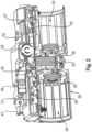
- Fig. 2 , 3 each show a longitudinal section through a common housing 28 for the two electric motors 17 of the two pump-motor units 18 with a first receiving section 29 for the first electric motor 17 of the damping system 10a and a second receiving section 30 for the second electric motor 17 of the damping system 10b.
- the two electric motors 17 of the two damping systems 10a, 10b are arranged in the two receiving sections 29, 30, the axes of rotation of the electric motors 17 are axially aligned.
- the common control device 27, which has the electronic components for controlling the electric motors 17, has at least one circuit board, in the embodiment shown two circuit boards 31, 32.
- the respective circuit board 31, 32 extends laterally next to the electric motors 17 parallel to the rotation axes of the electric motors 17 in the common housing 28 along the receiving sections 29, 30 for the Fig. 2 and 3 electric motors not shown.
- the control device 27 has an intermediate circuit capacitor 33 as an essential component.
- the intermediate circuit capacitor 33 is a high-voltage component of the control device 27, which is connected between a high-voltage connection 34 of the control device 27 and a DC/AC converter of the same.
- the DC/AC converters are used to convert direct voltage into alternating voltage in order to supply the electric motors 17 with electrical voltage or electrical current.
- the control device 27 has a DC/AC converter, each of which has three power semiconductor switches 35.
- Fig. 2 shows two power semiconductor switches 35 of the DC/AC converter for the electric motor 17 to be arranged in the receiving chamber 29 and one power semiconductor switch 35 of the DC/AC converter for the electric motor 17 to be arranged in the receiving space 30, wherein Fig. 3 the other power semiconductor switches 35 of the DC/AC converters.
- the intermediate circuit capacitor 33 extends from a circuit board 31 perpendicular to the circuit board 31 and thus perpendicular to the rotation axes of the electric motors 17 into a free space 36 of the housing 28 between the electric motors 17, so that it is arranged between the electric motors 17 or between the two receiving spaces 29, 30.
- the common control device 27 for the two electric motors 17 preferably has several circuit boards, namely in the embodiment shown the two circuit boards 31, 32.
- a first circuit board 32 has a low-voltage area with low-voltage components and a high-voltage area with high-voltage components that is galvanically separated from the low-voltage area.
- a second circuit board 31 has only high-voltage components and is electrically connected to the high-voltage area of the first circuit board 32, preferably via at least one ribbon cable 37 (see Fig. 3 ).
- the two circuit boards 31, 32 extend laterally within the housing 28 next to the receiving spaces 29, 30 and thus laterally next to the electric motors 17 to be accommodated by them, parallel to the rotation axes of the electric motors 17, with the second circuit board 31 being arranged between the electric motors 17 and the first circuit board 32.
- the second circuit board 31 carries the intermediate circuit capacitor 33, which extends from a side of the second circuit board 31 facing the electric motors 17 into the free space 36 between the electric motors 17.
- the second circuit board 31 has a common mode choke 38.
- the common mode choke 38 is also referred to as a common mode choke.
- the common mode choke 38 is arranged on a side of the second circuit board 31 facing away from the electric motors 17 and extends through a recess 39 in the first circuit board 32 in the opposite direction to the intermediate circuit capacitor 33.
- the second board 31 therefore has the high-voltage connection 32, the intermediate circuit capacitor 33, the common mode choke 38 and the DC/AC converters formed by the power semiconductor switches 35 as high-voltage components.
- the first circuit board 31 is, as already explained, divided into the low-voltage area with the low-voltage modules and the high-voltage area with the high-voltage modules, wherein the low-voltage area is separated from the high-voltage area by galvanic isolation.
- the low-voltage components of the low-voltage area of the first circuit board 32 include a low-voltage connection 40, a low-voltage distributor 41 and a signal converter 42, which converts analog CAN signals into digital CAN signals.
- the high-voltage components of the high-voltage area of the first board 32 include in particular a CPU 43, which also serves to control the DC/AC converters of the second board 31.
- the CPU 43 provides a high-voltage control for the high-voltage DC/AC converters of both electric motors 17.
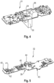
- the CPU 43 is in Fig. 5 arranged on the underside of the first board 32.
- a transformer assembly 44 and a digital isolator 45 are connected between the CPU 43 and the low-voltage area of the first board 31 as isolating components for galvanic isolation.
- the CPU 43 is thus galvanically decoupled from the low-voltage area on both the voltage side and the signal side.
- Fig. 2 , 3 further show a high-voltage connector 46 for contacting the high-voltage connection 34 of the second circuit board 31 and a low-voltage connector 47 for contacting the low-voltage connection 40 of the first circuit board 32.
- the operating voltage of the low-voltage modules is less than 50 volts, preferably less than 25 volts, particularly preferably less than 15 volts.
- the operating voltage of the high-voltage modules is greater than 200 V, preferably greater than 400 volts, particularly preferably greater than 500 volts.
- the common control device 27 has a particularly compact design, so that ultimately a compact design can also be ensured for the damping arrangement.
- each axle is assigned a damping arrangement.
Landscapes
- Engineering & Computer Science (AREA)
- Mechanical Engineering (AREA)
- Power Engineering (AREA)
- Microelectronics & Electronic Packaging (AREA)
- Vehicle Body Suspensions (AREA)
Abstract
Description
- Die Erfindung betrifft eine Dämpfungsanordnung für eine Achse eines aktiven Fahrwerks eines Kraftfahrzeugs und ein Kraftfahrzeug.
-
DE 10 2017 117 658 B4 undDE 10 2019 115 492 B4 offenbaren jeweils ein Dämpfungssystem für ein Rad eines Kraftfahrzeugs, welches einen Dämpfer, eine von einem Elektromotor angetriebene Hydraulikpumpe, ein Hydraulikreservoir sowie mehrere Ventile aufweist. Der Dämpfer ist von einem doppelt-wirkenden Hydraulikzylinder und einem in demselben hin und her bewegbaren Kolben gebildet. Die Hydraulikpumpe ist über Hydraulikleitungen mit Hydraulikkammern des Hydraulikkolbens gekoppelt, wobei abhängig von der Förderrichtung der Hydraulikpumpe eine Bewegung des Kolbens in einer ersten Betätigungsrichtung oder in einer zweiten Betätigungsrichtung bereitstellbar ist. - Eine Dämpfungsanordnung einer Achse eines aktiven Fahrwerks verfügt über zwei Dämpfungssysteme, wobei mit jedem Rad der Achse ein Dämpfungssystem zusammenwirkt. Jedes Dämpfungssystem verfügt dabei typischerweise über ein separates Steuergerät, über welches der jeweilige Elektromotor angesteuert werden kann.
-
DE 10 2019 118 384 A1 offenbart eine Vorrichtung zur Bereitstellung von hydraulischer Energie in einem Fahrwerksystem, welches eine erste hydraulische Pumpe, einen ersten Elektromotor zum Antreiben derselben, eine zweite hydraulische Pumpe, einen zweiten Elektromotor zum Antreiben derselben und eine gemeinsame Elektronikeinheit aufweist. Diese gemeinsame Elektronikeinheit ist eingerichtet, den ersten und zweiten Elektromotor anzusteuern und so die beiden hydraulischen Pumpen zu betreiben. Die Elektronikeinheit benötigt relativ viel Bauraum zwischen den Elektromotoren. -
- Aufgabe der Erfindung ist es, eine Dämpfungsanordnung für eine Achse eines aktiven Fahrwerks bereitzustellen, dessen Steuerungseinrichtung besonders wenig Bauraum benötigt, um so eine kompakt bauende Dämpfungsanordnung bereitzustellen. Ferner soll ein Kraftfahrzeug mit einer solchen kompakt bauenden Dämpfungsanordnung bereitgestellt werden.
- Diese Aufgabe wird durch eine Dämpfungsanordnung gemäß Patentanspruch 1 und durch ein Kraftfahrzeug gemäß Patentanspruch 10 gelöst.
- Bei der erfindungsgemäßen Dämpfungsanordnung sind die Elektromotoren beider Dämpfungssystemen mit axial fluchtenden Rotationsachsen in einem Gehäuse angeordnet.
- Bei der erfindungsgemäßen Dämpfungsanordnung sind die Elektromotoren beider Dämpfungssystemen von einer gemeinsamen Steuerungseinrichtung ansteuerbar.
- Die gemeinsame Steuerungseinrichtung weist elektronische Baugruppen auf, die auf mindestens einer Platine angeordnet sind, wobei sich die mindestens eine Platine seitlich neben den Elektromotoren parallel zu den Rotationsachsen der Elektromotoren erstreckt.
- Ein Zwischenkreiskondensator der gemeinsamen Steuerungseinrichtung erstreckt sich ausgehend von einer jeweiligen Patine senkrecht zu den Rotationsachsen der Elektromotoren in einen Freiraum zwischen den Elektromotoren hinein.
- Die Erfindung stellt eine besonders kompakt bauende Dämpfungsanordnung bereit.
- Die beiden Elektromotoren sind von einer gemeinsamen Steuerungseinrichtung aus ansteuerbar, wobei die mindestens eine Platine der Steuerungseinrichtung, welche die elektronischen Baugruppen zur Ansteuerung der Elektromotoren aufweist bzw. trägt, sich parallel zu den Rotationsachsen der Elektromotoren seitlich neben den Elektromotoren erstreckt. Der Zwischenkreiskondensator erstreckt sich ausgehend von einer Platine in den Freiraum zwischen den Elektromotoren. Hierdurch kann die Steuerungseinrichtung besonders bauraumsparend ausgeführt werden, wodurch letztendlich eine kompakt bauende Dämpfungsanordnung bereitgestellt werden kann.
- Vorzugsweise sind die Elektromotoren beider Dämpfungssysteme in einem gemeinsamen Gehäuse angeordnet, wobei die mindestens eine Platine der gemeinsamen Steuerungseinrichtung auch in dem gemeinsamen Gehäuse angeordnet ist, und wobei der Freiraum zwischen den Elektromotoren, in den sich der Zwischenkreiskondensator hinein erstreckt, von dem gemeinsamen Gehäuse ausgebildet ist. Auch hierdurch kann die Steuerungseinrichtung besonders bauraumsparend ausgeführt werden, wodurch letztendlich eine kompakt bauende Dämpfungsanordnung bereitgestellt werden kann.
- Vorzugsweise sind die elektronischen Baugruppen der gemeinsamen Steuerungseinrichtung auf unterschiedliche Platinen derart verteilt, dass eine erste Platine einen Niedervoltbereich mit Niedervolt-Baugruppen und einen galvanisch vom Niedervoltbereich getrennten Hochvoltbereich mit Hochvolt-Baugruppen aufweist, dass eine zweite Platine ausschließlich Hochvolt-Baugruppen aufweist und mit dem Hochvoltbereich der ersten Platine elektrisch verbunden ist, dass die zweite Platine zwischen den Elektromotoren und der ersten Platine angeordnet ist, und dass die zweite Platine den Zwischenkreiskondensator trägt, der sich ausgehend von einer den Elektromotoren zugewandten Seite der zweiten Platine in den Freiraum zwischen den Elektromotoren hinein erstreckt. Diese Ausführung ist besonders bevorzugt, um eine kompakt bauende Steuerungseinrichtung und damit eine kompakt bauendes Dämpfungsanordnung bereitzustellen.
- Vorzugsweise trägt die zweite Platine als weitere Hochvolt-Baugruppe eine Gleichtaktdrossel, die auf einer von den Elektromotoren abgewandten Seite der zweiten Platine angeordnet ist, wobei die erste Platine eine Aussparung für die Gleichtaktdrossel aufweist, durch welche sich die Gleichtaktdrossel erstreckt. Auch dies ist besonders bevorzugt, um eine kompakt bauende Steuerungseinrichtung und damit eine kompakt bauende Dämpfungsanordnung bereitzustellen.
- Die Betriebsspannung der Niedervolt-Baugruppen ist kleiner als 50 Volt, bevorzugt kleiner als 25 Volt, besonders bevorzugt kleiner als 15 Volt. Die Betriebsspannung der Hochvolt-Baugruppen ist größer als 200 V, bevorzugt größer als 400 Volt, besonders bevorzugt größer als 500 Volt.
- Bevorzugte Weiterbildungen der Erfindung ergeben sich aus den Unteransprüchen und der nachfolgenden Beschreibung. Ausführungsbeispiele der Erfindung werden, ohne hierauf beschränkt zu sein, anhand der Zeichnung näher erläutert. Dabei zeigt:
- Fig. 1
- eine schematisierte Darstellung einer erfindungsgemäßen Dämpfungsanordnung für die Räder einer Achse eines erfindungsgemäßen Kraftfahrzeugs;
- Fig. 2
- einen ersten Querschnitt durch die erfindungsgemäße Dämpfungsanordnung im Bereich einer Steuerungseinrichtung;
- Fig. 3
- einen zweiten Querschnitt durch die erfindungsgemäße Dämpfungsanordnung im Bereich der Steuerungseinrichtung;
- Fig. 4
- eine erste Platine der Steuerungseinrichtung;
- Fig. 5
- eine zweite Platine der Steuerungseinrichtung.
-
Fig. 1 zeigt stark schematisiert eine erfindungsgemäße Dämpfungsanordnung für zwei Räder einer Ache eines aktiven Fahrwerks eines Kraftfahrzeugs. Die Dämpfungsanordnung des aktiven Fahrwerks weist für jedes Rad ein Dämpfungssystem 10a, 10b auf. - Jedes der Dämpfungssysteme 10a, 10b verfügt über einen Dämpfer 11, welcher an ein nicht gezeigtes Radaufhängungssystem für das jeweilige nicht gezeigte Rad koppelbar ist. Der jeweilige Dämpfer 11 ist von einem doppelt-wirkenden Hydraulikzylinder 12 und einem Kolben 13 gebildet, wobei der Kolben 13 im Hydraulikzylinder 12 hin und her bewegbar ist, und zwar in
Fig. 1 nach oben und unten. - Der als doppelt-wirkender Hydraulikzylinder ausgebildete Hydraulikzylinder 12 jedes der Dämpfungssysteme 10a, 10b verfügt zu jeder Seite des Kolbens 13 über eine Hydraulikkammer 14, 15. Abhängig davon, welchen der beiden Hydraulikkammern 14, 15 Hydrauliköl zugeführt wird und von welcher der beiden Hydraulikkammern 15, 14 Hydrauliköl abgeführt wird, kann der Kolben 13 entweder in einer ersten Betätigungsrichtung oder in einer entgegengesetzten zweiten Betätigungsrichtung verlagert werden. Bei der ersten Betätigungsrichtung des Kolbens 13 handelt es sich um eine Betätigung in Zugrichtung und bei der zweiten Betätigungsrichtung des Kolbens 13 um eine Betätigung in Druckrichtung.
- Das jeweilige Dämpfungssystem 10a, 10b verfügt weiterhin über eine Hydraulikpumpe 16, die von einem jeweiligen Elektromotor 17 aus antreibbar ist. Hydraulikpumpe 16 und Elektromotor 17 bilden eine jeweilige Pumpen-Motor-Einheit 18. Bei der Hydraulikpumpe 16 handelt es sich um eine Reversierpumpe, die zur Bereitstellung unterschiedlicher Förderrichtungen vom jeweiligen Elektromotor 17 in unterschiedlichen Drehrichtungen angetrieben werden kann.
- Das jeweilige Dämpfungssystem 10a, 10b der
Fig. 1 verfügt weiterhin über eine Hydraulikeinheit 19, die ein Hydraulikreservoir 20 sowie Ventile 21, 22, 23, 24 aufweist. Bei den Ventilen 21, 22 handelt es sich um Rückschlagventile und bei den Ventilen 23, 24 um Dämpfungsventile. Das Hydraulikreservoir 20 jedes der Dämpfungssysteme 10a, 10b greift jeweils zwischen den Rückschlagventilen 21, 22 und zwischen den Dämpfungsventilen 23, 24 an Hydraulikleitungen der Hydraulikeinheit 19 an, die mit den Hydraulikkammern 14, 15 gekoppelt sind. - Abhängig von der Förderrichtung der Hydraulikpumpe 16 und vorzugsweise auch abhängig von der Stellung der Ventile 21, 22, 23, 24 des jeweiligen Dämpfungssystems 10a, 10b wird zur Verlagerung des Kolbens 13 in der ersten Bewegungsrichtung, also in Zugrichtung, der Hydraulikkammer 14 Öl zugeführt und von der Hydraulikkammer 15 Öl abgeführt, oder zur Bereitstellung einer zweiten Bewegungsrichtung des Kolbens 13 in der zweiten Bewegungsrichtung, also in Druckrichtung, der Hydraulikkammer 15 Öl zugeführt und von der Hydraulikkammer 14 Öl abgeführt.
- Die Hydraulikpumpe 16 der Pumpen-Motor-Einheit 18 des jeweiligen Dämpfungssystems 10a, 10b ist mit der das Hydraulikreservoir 20 und die Ventile 21, 22, 23, 24 umfassenden Hydraulikeinheit 19, die vorzugsweise als Einheit am Dämpfer 11 bzw. am Hydraulikzylinder 12 verbaut ist, über Hydraulikleitungen 25, 26 verbunden.
- Die Elektromotoren 17 beider Dämpfungssystemen 10a, 10b sind von einer gemeinsamen Steuerungseinrichtung 27 aus ansteuerbar. Die gemeinsame Steuerungseinrichtung 27 verfügt über elektronische Baugruppen, die der Ansteuerung der Elektromotoren 17 dienen.
- Die Elektromotoren 17 der beiden Pumpen-Motor-Einheiten 18 sind in einem Gehäuse 28, vorzugsweise in einem gemeinsamen Gehäuse 28, aufgenommen.
-
Fig. 2 ,3 zeigen jeweils einen Längsschnitt durch ein gemeinsames Gehäuse 28 für die beiden Elektromotoren 17 der beiden Pumpen-Motor-Einheiten 18 mit einem ersten Aufnahmeabschnitt 29 für den ersten Elektromotor 17 des Dämpfungssystems 10a und einen zweiten Aufnahmeabschnitt 30 für den zweiten Elektromotor 17 des Dämpfungssystems 10b. Dann, wenn in den beiden Aufnahmeabschnitten 29, 30 die beiden Elektromotoren 17 der beiden Dämpfungssystemen 10a, 10b angeordnet sind, verlaufen Rotationsachsen der Elektromotoren 17 axial fluchtend. - Die gemeinsame Steuerungseinrichtung 27, welche die elektronischen Baugruppen zur Ansteuerung der Elektromotoren 17 aufweist, verfügt über mindestens eine Platine, im gezeigten Ausführungsbeispiel über zwei Platinen 31, 32. Die jeweilige Platine 31, 32 erstreckt sich seitlich neben den Elektromotoren 17 parallel zu den Rotationsachsen der Elektromotoren 17 im gemeinsamen Gehäuse 28 entlang der Aufnahmeabschnitte 29, 30 für die in
Fig. 2 und3 nicht gezeigten Elektromotoren. - Die Steuerungseinrichtung 27 verfügt als wesentliche Baugruppe über einen Zwischenkreiskondensator 33. Der Zwischenkreiskondensator 33 ist eine Hochvolt-Baugruppe der Steuerungseinrichtung 27, die zwischen einen Hochvolt-Anschluss 34 der Steuerungseinrichtung 27 und einen DC/AC-Wandler derselben geschaltet ist.
- Die DC/AC-Wandler dienen der Wandlung von Gleichspannung in Wechselspannung, um die Elektromotoren 17 mit elektrischer Spannung bzw. elektrischem Strom zu versorgen. Für jeden Elektromotor 17 verfügt die Steuerungseinrichtung 27 über einen DC/AC-Wandler, der jeweils drei Leistungshalbleiterschalter 35 aufweist.
Fig. 2 zeigt zwei Leistungshalbleiterschalter 35 des DC/AC-Wandlers für den in der Aufnahmekammer 29 anzuordnenden Elektromotor 17 und einen Leistungshalbleiterschalter 35 des DC/AC-Wandlers für den in dem Aufnahmeraum 30 anzuordnenden Elektromotor 17, wobeiFig. 3 die jeweils anderen Leistungshalbleiterschalter 35 der DC/AC-Wandler zeigt. Insgesamt sind demnach sechs Leistungshalbleiterschalter vorhanden, die vorzugsweise als IGBT-Transistoren bzw. bipolare Transistoren mit isolierter Gate-Elektrode ausgeführt sind. - Der Zwischenkreiskondensator 33 erstreckt sich ausgehend von einer Platine 31 senkrecht zu der Platine 31 und damit senkrecht zu den Rotationsachsen der Elektromotoren 17 in einen Freiraum 36 des Gehäuses 28 zwischen den Elektromotoren 17 hinein, sodass derselbe zwischen den Elektromotoren 17 bzw. zwischen den beiden Aufnahmeräumen 29, 30 angeordnet ist.
- Wie bereits ausgeführt, weist die gemeinsame Steuerungseinrichtung 27 für die beiden Elektromotoren 17 vorzugsweise mehrere Platinen auf, nämlich im gezeigten Ausführungsbeispiel die beiden Platinen 31, 32. Eine erste Platine 32 weist dabei einen Niedervoltbereich mit Niedervolt-Baugruppen und einen galvanisch vom Niedervoltbereich getrennten Hochvoltbereich mit Hochvolt-Baugruppen auf. Eine zweite Platine 31 verfügt ausschließlich über Hochvolt-Baugruppen und ist mit dem Hochvoltbereich der ersten Platine 32 elektrisch verbunden, vorzugsweise über mindestens ein Flachbandkabel 37 (siehe
Fig. 3 ). - Die beiden Platinen 31, 32 erstrecken sich seitlich innerhalb des Gehäuses 28 neben den Aufnahmeräumen 29, 30 und damit seitlich neben den von denselben aufzunehmenden Elektromotoren 17 parallel zu den Rotationsachsen der Elektromotoren 17, wobei die zweite Platine 31 zwischen den Elektromotoren 17 und der ersten Platine 32 angeordnet ist. Die zweite Platine 31 trägt dabei den Zwischenkreiskondensator 33, der sich ausgehend von einer den Elektromotoren 17 zugewandten Seite der zweiten Platine 31 in den Freiraum 36 zwischen den Elektromotoren 17 hinein erstreckt.
- Als weitere Hochvolt-Baugruppe weist die zweite Platine 31 eine Gleichtaktdrossel 38 auf. Die Gleichtaktdrossel 38 wird auch als Common Mode Choke bezeichnet.
- Die Gleichtaktdrossel 38 ist auf einer von den Elektromotoren 17 abgewandten Seite der zweiten Platine 31 angeordnet und erstreckt sich durch eine Aussparung 39 in der ersten Platine 32 in die entgegengesetzte Richtung wie der Zwischenkreiskondensator 33.
- Die zweite Platine 31 verfügt demnach als Hochvolt-Baugruppen über den Hochvolt-Anschluss 32, den Zwischenkreiskondensator 33, die Gleichtaktdrossel 38 sowie die von den Leistungshalbleiterschaltern 35 gebildeten DC/AC-Wandler.
- Die erste Platine 31 ist, wie bereits ausgeführt, in den Niedervoltbereich mit den Niedervolt-Baugruppen und den Hochvoltbereich mit den Hochvolt-Baugruppen untergliedert, wobei der Niedervoltbereich von dem Hochvoltbereich über eine galvanische Isolation getrennt ist.
- Zu den Niedervolt-Baugruppen des Niedervoltbereichs der ersten Platine 32 zählt ein Niedervolt-Anschluss 40, ein Niedervolt-Verteiler 41 sowie ein Signalwandler 42, welcher analoge CAN-Signale in digitale CAN-Signale wandelt.
- Zu den Hochvolt-Baugruppen des Hochvoltbereichs der ersten Platine 32 zählt insbesondere eine CPU 43, die auch der Ansteuerung der DC/AC-Wandler der zweiten Platine 31 dient. Die CPU 43 stellt eine Hochvolt-Ansteuerung für die hochvoltseitigen DC/AC-Wandler beider Elektromotoren 17 bereit. Die CPU 43 ist in
Fig. 5 auf der Unterseite der ersten Platine 32 angeordnet. - Zwischen die CPU 43 und den Niedervoltbereich der ersten Platine 31 sind als Trennbaugruppen der galvanischen Isolation eine Transformator-Baugruppe 44 und ein Digital-Isolator 45 geschaltet. So ist die CPU 43 sowohl spannungsseitig als auch signalseitig galvanisch vom Niederspannungsbereich entkoppelt.
-
Fig. 2 ,3 zeigen weiterhin einen Hochvolt-Steckverbinder 46 zur Kontaktierung des Hochvolt-Anschlusses 34 der zweiten Platine 31 und einen Niedervolt-Steckverbinder 47 zur Kontaktierung des Niedervolt-Anschlusses 40 der ersten Platine 32. - Die Betriebsspannung der Niedervolt-Baugruppen ist kleiner als 50 Volt, bevorzugt kleiner als 25 Volt, besonders bevorzugt kleiner als 15 Volt. Die Betriebsspannung der Hochvolt-Baugruppen ist größer als 200 V, bevorzugt größer als 400 Volt, besonders bevorzugt größer als 500 Volt.
- Die gemeinsame Steuerungseinrichtung 27 verfügt über eine besonders kompakte Bauform, sodass letztendlich auch für die Dämpfungsanordnung eine kompakte Bauform gewährleistet werden kann.
- Bei einem Kraftfahrzeug mit mehreren Achsen ist jeder Achse eine Dämpfungsanordnung zugeordnet.
Claims (10)
- Dämpfungsanordnung für eine Achse eines aktiven Fahrwerks eines Kraftfahrzeugs, wobei mit jedem Rad der Achse ein Dämpfungssystem (10a, 10b) zusammenwirkt, wobei jedes der Dämpfungssysteme (10a, 10b) folgende Baugruppen aufweist:einen Dämpfer (11), der einen doppelt-wirkenden Hydraulikzylinder (12) und einen Kolben (13) aufweist, wobei der Dämpfer (11) mit einem Radaufhängungssystem des jeweiligen Rads koppelbar ist,eine Hydraulikpumpe (16) und einen Elektromotor (17) zum Antreiben der jeweiligen Hydraulikpumpe (16), wobei die Hydraulikpumpe (16) eine Reversierpumpe ist, die zur Bereitstellung unterschiedlicher Förderrichtungen vom Elektromotor (17) in unterschiedlichen Drehrichtungen antreibbar ist,eine ein Hydraulikreservoir (20) und Ventile (21, 22, 23, 24) aufweisende Hydraulikeinheit (19), wobei die Hydraulikpumpe (16) und die Hydraulikeinheit (19) des jeweiligen Dämpfungssystems (10a, 10b) mit Hydraulikkammern (14, 15) des Hydraulikzylinders (13) des jeweiligen Dämpfungssystems (10a, 10b) derart zusammenwirken, dass abhängig von der Förderrichtung der Hydraulikpumpe (16) eine Bewegung des Kolbens (13) in einer ersten Betätigungsrichtung oder in einer zweiten Betätigungsrichtung bereitstellbar ist,dadurch gekennzeichnet, dassdie Elektromotoren (17) beider Dämpfungssysteme (10a, 10b) mit axial fluchtenden Rotationsachsen in einem Gehäuse (28) angeordnet sind,die Elektromotoren (17) beider Dämpfungssysteme (10a, 10b) von einer gemeinsamen Steuerungseinrichtung (27) ansteuerbar sind,die gemeinsame Steuerungseinrichtung (27) elektronische Baugruppen aufweist, die auf mindestens einer Platine (31, 32) angeordnet sind,wobei sich die mindestens eine Platine (31, 32) seitlich neben den Elektromotoren (17) parallel zu den Rotationsachsen der Elektromotoren (17) erstreckt,wobei sich ein Zwischenkreiskondensator (33) der gemeinsamen Steuerungseinrichtung (27) ausgehend von einer jeweiligen Patine (31) senkrecht zu den Rotationsachsen der Elektromotoren (17) in einen Freiraum zwischen den Elektromotoren (17) hinein erstreckt.
- Dämpfungsanordnung nach Anspruch 1, wobei
die Elektromotoren (17) beider Dämpfungssysteme (10a, 10b) in einem gemeinsamen Gehäuse (28) angeordnet sind. - Dämpfungsanordnung nach Anspruch 2, wobei
die mindestens eine Platine (31, 32) der Steuerungseinrichtung (27) auch in dem gemeinsamen Gehäuse (28) angeordnet ist. - Dämpfungsanordnung nach Anspruch 2 oder 3, wobei
der Freiraum zwischen den Elektromotoren (17), in den sich der Zwischenkreiskondensator (33) hinein erstreckt, von dem gemeinsamen Gehäuse (28) ausgebildet ist. - Dämpfungsanordnung nach einem der Ansprüche 1 bis 4, wobei
die elektronischen Baugruppen der gemeinsamen Steuerungseinrichtung (27) auf unterschiedliche Platinen (31, 32) derart verteilt sind, dasseine erste Platine (32) einen Niedervoltbereich mit Niedervolt-Baugruppen und einen galvanisch vom Niedervoltbereich getrennten Hochvoltbereich mit Hochvolt-Baugruppen aufweist,eine zweite Platine (31) ausschließlich Hochvolt-Baugruppen aufweist und mit dem Hochvoltbereich der ersten Platine elektrisch verbunden ist,die zweite Platine (31) zwischen den Elektromotoren (17) und der ersten Platine (32) angeordnet ist,die zweite Platine (31) den Zwischenkreiskondensator (33) trägt, der sich ausgehend von einer den Elektromotoren (17) zugewandten Seite der zweiten Platine (31) in den Freiraum zwischen den Elektromotoren (17) hinein erstreckt. - Dämpfungsanordnung nach Anspruch 5, wobei
die zweite Platine (31) mit dem Hochvoltbereich der ersten Platine (32) über mindestens ein Flachbandkabel (37) elektrisch verbunden ist. - Dämpfungsanordnung nach Anspruch 5 oder 6, wobei
die zweite Platine (31) als weitere Hochvolt-Baugruppe eine Gleichtaktdrossel (38) aufweist, die auf einer von den Elektromotoren (17) abgewandten Seite der zweiten Platine (31) angeordnet ist. - Dämpfungsanordnung nach Anspruch 7, wobei
die erste Platine (32) eine Aussparung (39) für die Gleichtaktdrossel (38) aufweist, durch welche sich die Gleichtaktdrossel (38) erstreckt. - Dämpfungsanordnung nach einem der Ansprüche 5 bis 8, wobeidie Betriebsspannung der Niedervolt-Baugruppen kleiner als 50 Volt ist, bevorzugt kleiner als 25 Volt ist, besonders bevorzugt kleiner als 15 Volt ist,die Betriebsspannung der Hochvolt-Baugruppen größer als 200 Volt ist, bevorzugt größer als 400 Volt ist, besonders bevorzugt größer als 500 Volt ist.
- Kraftfahrzeug, mit mehreren Achsen, wobei jeder Achse eine Dämpfungsanordnung nach einem der Ansprüche 1 bis 9 zugeordnet ist.
Applications Claiming Priority (1)
| Application Number | Priority Date | Filing Date | Title |
|---|---|---|---|
| DE102023108630.8A DE102023108630A1 (de) | 2023-04-04 | 2023-04-04 | Dämpfungsanordnung für eine Achse eines Kraftfahrzeugs und Kraftfahrzeug |
Publications (2)
| Publication Number | Publication Date |
|---|---|
| EP4446140A1 true EP4446140A1 (de) | 2024-10-16 |
| EP4446140B1 EP4446140B1 (de) | 2025-12-17 |
Family
ID=92799931
Family Applications (1)
| Application Number | Title | Priority Date | Filing Date |
|---|---|---|---|
| EP24166191.7A Active EP4446140B1 (de) | 2023-04-04 | 2024-03-26 | Dämpfungsanordnung für eine achse eines kraftfahrzeugs und kraftfahrzeug |
Country Status (4)
| Country | Link |
|---|---|
| US (1) | US12325275B2 (de) |
| EP (1) | EP4446140B1 (de) |
| CN (1) | CN118775486A (de) |
| DE (1) | DE102023108630A1 (de) |
Citations (9)
| Publication number | Priority date | Publication date | Assignee | Title |
|---|---|---|---|---|
| DE10051620A1 (de) | 1999-10-18 | 2001-05-17 | Kanzaki Kokyukoki Mfg Co Ltd | Tandem-Pumpeneinheit |
| EP2187055A1 (de) * | 2007-11-06 | 2010-05-19 | Mitsubishi Heavy Industries, Ltd. | Elektrischer verdichter für eine fahrzeug-klimaanlage |
| WO2012023692A1 (ko) * | 2010-08-17 | 2012-02-23 | 학교법인 두원학원 | 차량용 전동식압축기 |
| DE102012204212A1 (de) | 2012-03-16 | 2013-09-19 | Mahle International Gmbh | Pumpenmodul mit einem Gehäuse |
| EP2864638B1 (de) | 2012-05-04 | 2017-09-27 | Ghsp, Inc. | Doppelpumpe und motor mit steuerungsvorrichtung |
| DE102019118384A1 (de) | 2019-07-08 | 2021-01-14 | Rapa Automotive Gmbh & Co. Kg | Mpe-achssatz mit gemeinsamer ecu |
| DE102019130841B3 (de) * | 2019-11-15 | 2021-02-25 | Dr. Ing. H.C. F. Porsche Aktiengesellschaft | Motor-Pumpen-Einheit für eine Druckstellanordnung sowie Achs-oder Tandem- Motor-Pumpenanordnung sowie Druckstellanordnung |
| DE102017117658B4 (de) | 2017-08-03 | 2021-06-02 | Dr. Ing. H.C. F. Porsche Aktiengesellschaft | Kraftfahrzeug mit einem Dämpfungssystem |
| DE102019115492B4 (de) | 2019-06-07 | 2022-08-11 | Dr. Ing. H.C. F. Porsche Aktiengesellschaft | Dämpferanordnung für ein Rad eines Kraftfahrzeuges |
Family Cites Families (4)
| Publication number | Priority date | Publication date | Assignee | Title |
|---|---|---|---|---|
| DE10256278A1 (de) * | 2002-12-03 | 2004-06-24 | Daimlerchrysler Ag | Federsystem für Fahrzeuge, insbesondere Personenkraftwagen |
| DE102023106354B3 (de) * | 2023-03-14 | 2024-07-25 | Dr. Ing. H.C. F. Porsche Aktiengesellschaft | Motor-Pumpe-Einheit eines aktiven Schwingungsdämpfungssystems eines Kraftfahrzeugs |
| DE102023108059A1 (de) * | 2023-03-29 | 2024-10-02 | Rapa Automotive Gmbh & Co. Kg | Elektronikbaukasten |
| US12220963B2 (en) * | 2023-04-18 | 2025-02-11 | DRiV Automotive Inc. | Modular load distribution unit and assembly method |
-
2023
- 2023-04-04 DE DE102023108630.8A patent/DE102023108630A1/de active Pending
-
2024
- 2024-03-22 US US18/613,470 patent/US12325275B2/en active Active
- 2024-03-26 EP EP24166191.7A patent/EP4446140B1/de active Active
- 2024-03-28 CN CN202410368483.4A patent/CN118775486A/zh active Pending
Patent Citations (9)
| Publication number | Priority date | Publication date | Assignee | Title |
|---|---|---|---|---|
| DE10051620A1 (de) | 1999-10-18 | 2001-05-17 | Kanzaki Kokyukoki Mfg Co Ltd | Tandem-Pumpeneinheit |
| EP2187055A1 (de) * | 2007-11-06 | 2010-05-19 | Mitsubishi Heavy Industries, Ltd. | Elektrischer verdichter für eine fahrzeug-klimaanlage |
| WO2012023692A1 (ko) * | 2010-08-17 | 2012-02-23 | 학교법인 두원학원 | 차량용 전동식압축기 |
| DE102012204212A1 (de) | 2012-03-16 | 2013-09-19 | Mahle International Gmbh | Pumpenmodul mit einem Gehäuse |
| EP2864638B1 (de) | 2012-05-04 | 2017-09-27 | Ghsp, Inc. | Doppelpumpe und motor mit steuerungsvorrichtung |
| DE102017117658B4 (de) | 2017-08-03 | 2021-06-02 | Dr. Ing. H.C. F. Porsche Aktiengesellschaft | Kraftfahrzeug mit einem Dämpfungssystem |
| DE102019115492B4 (de) | 2019-06-07 | 2022-08-11 | Dr. Ing. H.C. F. Porsche Aktiengesellschaft | Dämpferanordnung für ein Rad eines Kraftfahrzeuges |
| DE102019118384A1 (de) | 2019-07-08 | 2021-01-14 | Rapa Automotive Gmbh & Co. Kg | Mpe-achssatz mit gemeinsamer ecu |
| DE102019130841B3 (de) * | 2019-11-15 | 2021-02-25 | Dr. Ing. H.C. F. Porsche Aktiengesellschaft | Motor-Pumpen-Einheit für eine Druckstellanordnung sowie Achs-oder Tandem- Motor-Pumpenanordnung sowie Druckstellanordnung |
Also Published As
| Publication number | Publication date |
|---|---|
| EP4446140B1 (de) | 2025-12-17 |
| DE102023108630A1 (de) | 2024-10-10 |
| US20240336102A1 (en) | 2024-10-10 |
| US12325275B2 (en) | 2025-06-10 |
| CN118775486A (zh) | 2024-10-15 |
Similar Documents
| Publication | Publication Date | Title |
|---|---|---|
| EP3764522A1 (de) | Mpe-achssatz mit gemeinsamer ecu | |
| DE102023108591A1 (de) | Dämpfungsanordnung für eine Achse eines Kraftfahrzeugs und Kraftfahrzeug | |
| WO1998042552A1 (de) | Elektrohydraulisches aggregat zur druckregelung in bremsanlagen für kraftfahrzeuge | |
| EP3736146A1 (de) | Energieversorgungseinheit für aktives fahrwerksystem | |
| EP4446140B1 (de) | Dämpfungsanordnung für eine achse eines kraftfahrzeugs und kraftfahrzeug | |
| EP0277602A2 (de) | Hydraulikanlage zur Betätigung von Arbeitsgeräten an Fahrzeugen | |
| DE102006015310B3 (de) | Sammelschienenkupplung | |
| DE102022133470B4 (de) | Konduktives Ladesystem mit Schutzleiter als Kontaktfläche, Elektrofahrzeug mit Ladesystem | |
| EP2115847A1 (de) | Kraftfahrzeug-steuergerät mit verpolschutz | |
| DE102020203010A1 (de) | Verfahren zum Betreiben eines Pumpenmotors einer Betätigungseinrichtung, Betätigungseinrichtung, Kraftfahrzeug | |
| EP4135490B1 (de) | Modular aufgebautes schnittstellenkonzept für einen elektrischen antrieb | |
| EP0342326B1 (de) | Halterbefestigung an einer druckmittelbetätigten Baugruppe | |
| EP0989016A2 (de) | Stromrichterschaltung mit variabler Konfiguration für Traktionsanwendungen | |
| EP1062851B1 (de) | Modulare leistungsendstufe | |
| DE102020205359A1 (de) | Baukastensystem für ein Bremsgerät einer hydraulische Kraftfahrzeugbremsanlage | |
| EP4015876A1 (de) | Fahrzeug-mechaniksystem | |
| DE102020132476A1 (de) | Einseitig gelagerte schneckenradbaugruppe mit bremsbuchse | |
| WO2019092151A1 (de) | Elektronik mit einer oder mehreren endstufeneinheiten für den betrieb von zwei oder mehreren motoreinheiten | |
| DE102020216347B4 (de) | Antriebsanordnung für einen Scherenhub mit einer mechanischen Vorspannung | |
| DE10127868A1 (de) | Bootstrap-Spannungsversorgung | |
| DE102018117715A1 (de) | Antriebsvorrichtung und diese verwendender Fensterheberaktuator | |
| WO2005075852A2 (de) | Aktor, insbesondere für ein fahrwerk | |
| DE202025105188U1 (de) | Kolben-Zylinder-Einheit sowie Verstelleinrichtung mit einer Kolben-Zylinder-Einheit | |
| EP0596214B1 (de) | Magnetbetätigbares Ventil | |
| DE102023120869A1 (de) | Elektronische Komponente für ein Fahrzeug |
Legal Events
| Date | Code | Title | Description |
|---|---|---|---|
| PUAI | Public reference made under article 153(3) epc to a published international application that has entered the european phase |
Free format text: ORIGINAL CODE: 0009012 |
|
| STAA | Information on the status of an ep patent application or granted ep patent |
Free format text: STATUS: THE APPLICATION HAS BEEN PUBLISHED |
|
| AK | Designated contracting states |
Kind code of ref document: A1 Designated state(s): AL AT BE BG CH CY CZ DE DK EE ES FI FR GB GR HR HU IE IS IT LI LT LU LV MC ME MK MT NL NO PL PT RO RS SE SI SK SM TR |
|
| STAA | Information on the status of an ep patent application or granted ep patent |
Free format text: STATUS: REQUEST FOR EXAMINATION WAS MADE |
|
| 17P | Request for examination filed |
Effective date: 20250415 |
|
| P01 | Opt-out of the competence of the unified patent court (upc) registered |
Free format text: CASE NUMBER: APP_18279/2025 Effective date: 20250415 |
|
| GRAP | Despatch of communication of intention to grant a patent |
Free format text: ORIGINAL CODE: EPIDOSNIGR1 |
|
| STAA | Information on the status of an ep patent application or granted ep patent |
Free format text: STATUS: GRANT OF PATENT IS INTENDED |
|
| INTG | Intention to grant announced |
Effective date: 20250916 |
|
| GRAS | Grant fee paid |
Free format text: ORIGINAL CODE: EPIDOSNIGR3 |
|
| GRAA | (expected) grant |
Free format text: ORIGINAL CODE: 0009210 |
|
| STAA | Information on the status of an ep patent application or granted ep patent |
Free format text: STATUS: THE PATENT HAS BEEN GRANTED |
|
| REG | Reference to a national code |
Ref country code: DE Ref legal event code: R081 Ref document number: 502024000507 Country of ref document: DE Owner name: DR. ING. H.C. F. PORSCHE AKTIENGESELLSCHAFT, DE Free format text: FORMER OWNER: RAPA AUTOMOTIVE GMBH & CO. KG, 95100 SELB, DE Ref country code: DE Ref legal event code: R081 Ref document number: 502024000507 Country of ref document: DE Owner name: RAPA AUTOMOTIVE GMBH & CO. KG, DE Free format text: FORMER OWNER: RAPA AUTOMOTIVE GMBH & CO. KG, 95100 SELB, DE |
|
| AK | Designated contracting states |
Kind code of ref document: B1 Designated state(s): AL AT BE BG CH CY CZ DE DK EE ES FI FR GB GR HR HU IE IS IT LI LT LU LV MC ME MK MT NL NO PL PT RO RS SE SI SK SM TR |
|
| REG | Reference to a national code |
Ref country code: CH Ref legal event code: F10 Free format text: ST27 STATUS EVENT CODE: U-0-0-F10-F00 (AS PROVIDED BY THE NATIONAL OFFICE) Effective date: 20251217 Ref country code: GB Ref legal event code: FG4D Free format text: NOT ENGLISH |
|
| REG | Reference to a national code |
Ref country code: DE Ref legal event code: R096 Ref document number: 502024000507 Country of ref document: DE |
|
| REG | Reference to a national code |
Ref country code: LT Ref legal event code: MG9D |
|
| PG25 | Lapsed in a contracting state [announced via postgrant information from national office to epo] |
Ref country code: NO Free format text: LAPSE BECAUSE OF FAILURE TO SUBMIT A TRANSLATION OF THE DESCRIPTION OR TO PAY THE FEE WITHIN THE PRESCRIBED TIME-LIMIT Effective date: 20260317 |
|
| PGFP | Annual fee paid to national office [announced via postgrant information from national office to epo] |
Ref country code: DE Payment date: 20260323 Year of fee payment: 3 |
|
| PG25 | Lapsed in a contracting state [announced via postgrant information from national office to epo] |
Ref country code: FI Free format text: LAPSE BECAUSE OF FAILURE TO SUBMIT A TRANSLATION OF THE DESCRIPTION OR TO PAY THE FEE WITHIN THE PRESCRIBED TIME-LIMIT Effective date: 20251217 Ref country code: HR Free format text: LAPSE BECAUSE OF FAILURE TO SUBMIT A TRANSLATION OF THE DESCRIPTION OR TO PAY THE FEE WITHIN THE PRESCRIBED TIME-LIMIT Effective date: 20251217 |
|
| PGFP | Annual fee paid to national office [announced via postgrant information from national office to epo] |
Ref country code: AT Payment date: 20260301 Year of fee payment: 3 |
|
| PG25 | Lapsed in a contracting state [announced via postgrant information from national office to epo] |
Ref country code: RS Free format text: LAPSE BECAUSE OF FAILURE TO SUBMIT A TRANSLATION OF THE DESCRIPTION OR TO PAY THE FEE WITHIN THE PRESCRIBED TIME-LIMIT Effective date: 20260317 |
|
| REG | Reference to a national code |
Ref country code: NL Ref legal event code: MP Effective date: 20251217 |
|
| PG25 | Lapsed in a contracting state [announced via postgrant information from national office to epo] |
Ref country code: LV Free format text: LAPSE BECAUSE OF FAILURE TO SUBMIT A TRANSLATION OF THE DESCRIPTION OR TO PAY THE FEE WITHIN THE PRESCRIBED TIME-LIMIT Effective date: 20251217 |