EP4445754A1 - Inspection apparatus and inspection method for filter rod - Google Patents
Inspection apparatus and inspection method for filter rod Download PDFInfo
- Publication number
- EP4445754A1 EP4445754A1 EP21967183.1A EP21967183A EP4445754A1 EP 4445754 A1 EP4445754 A1 EP 4445754A1 EP 21967183 A EP21967183 A EP 21967183A EP 4445754 A1 EP4445754 A1 EP 4445754A1
- Authority
- EP
- European Patent Office
- Prior art keywords
- filter rod
- inspection
- shading
- end portion
- image
- Prior art date
- Legal status (The legal status is an assumption and is not a legal conclusion. Google has not performed a legal analysis and makes no representation as to the accuracy of the status listed.)
- Pending
Links
Images


Classifications
-
- A—HUMAN NECESSITIES
- A24—TOBACCO; CIGARS; CIGARETTES; SIMULATED SMOKING DEVICES; SMOKERS' REQUISITES
- A24D—CIGARS; CIGARETTES; TOBACCO SMOKE FILTERS; MOUTHPIECES OF CIGARS OR CIGARETTES; MANUFACTURE OF TOBACCO SMOKE FILTERS OR MOUTHPIECES
- A24D3/00—Tobacco smoke filters, e.g. filter tips or filtering inserts; Filters specially adapted for simulated smoking devices; Mouthpieces of cigars or cigarettes
- A24D3/02—Manufacture of tobacco smoke filters
-
- A—HUMAN NECESSITIES
- A24—TOBACCO; CIGARS; CIGARETTES; SIMULATED SMOKING DEVICES; SMOKERS' REQUISITES
- A24C—MACHINES FOR MAKING CIGARS OR CIGARETTES
- A24C5/00—Making cigarettes; Making tipping materials for, or attaching filters or mouthpieces to, cigars or cigarettes
- A24C5/32—Separating, ordering, counting or examining cigarettes; Regulating the feeding of tobacco according to rod or cigarette condition
- A24C5/34—Examining cigarettes or the rod, e.g. for regulating the feeding of tobacco; Removing defective cigarettes
-
- A—HUMAN NECESSITIES
- A24—TOBACCO; CIGARS; CIGARETTES; SIMULATED SMOKING DEVICES; SMOKERS' REQUISITES
- A24C—MACHINES FOR MAKING CIGARS OR CIGARETTES
- A24C5/00—Making cigarettes; Making tipping materials for, or attaching filters or mouthpieces to, cigars or cigarettes
- A24C5/32—Separating, ordering, counting or examining cigarettes; Regulating the feeding of tobacco according to rod or cigarette condition
- A24C5/34—Examining cigarettes or the rod, e.g. for regulating the feeding of tobacco; Removing defective cigarettes
- A24C5/3412—Examining cigarettes or the rod, e.g. for regulating the feeding of tobacco; Removing defective cigarettes by means of light, radiation or electrostatic fields
-
- A—HUMAN NECESSITIES
- A24—TOBACCO; CIGARS; CIGARETTES; SIMULATED SMOKING DEVICES; SMOKERS' REQUISITES
- A24D—CIGARS; CIGARETTES; TOBACCO SMOKE FILTERS; MOUTHPIECES OF CIGARS OR CIGARETTES; MANUFACTURE OF TOBACCO SMOKE FILTERS OR MOUTHPIECES
- A24D3/00—Tobacco smoke filters, e.g. filter tips or filtering inserts; Filters specially adapted for simulated smoking devices; Mouthpieces of cigars or cigarettes
- A24D3/02—Manufacture of tobacco smoke filters
- A24D3/0295—Process control means
Definitions
- the present invention relates to an inspection apparatus and an inspection method for a filter rod, and, specifically, relates to an inspection apparatus and an inspection method, which, in a conveyance process, inspect a filter rod that becomes a filter element of a flavor inhalation article.
- the inspection apparatus includes a plurality of light sources that emit light beams of different wavelength distributions, an adjusting unit that forms inspection light from the light beams emitted from the respective light sources, an illuminating unit that illuminates the filter rod with the inspection light formed by the adjusting unit, a photodetector that receives measurement light obtained as a result of the inspection light applied from the illuminating unit acting upon the filter rod, and a determination unit that determines the quality of the filter rod based on the measurement light received by the photodetector.
- the adjusting unit adjusts the color of the inspection light by mixing the light beams emitted from the respective light sources.
- PTL 1 also discloses a filter rod manufacturing machine including the inspection apparatus above.
- the manufacturing machine includes a conveyance drum that conveys the filter rod, and the conveyance drum includes a cylindrical core in whose interior a suction source and the illuminating unit are disposed, and a drum shell that covers the cylindrical core and that is rotatably disposed with respect to the cylindrical core.
- the cylindrical core has a communication port that causes the suction source and the drum shell to communicate with each other in a peripheral direction thereof and a first illumination port at which the illuminating unit is positioned.
- the drum shell has a plurality of holding grooves that are arranged with an interval therebetween in a peripheral direction thereof and that each hold a filter rod, a suction hole that communicates with the communication port as the drum shell rotates, and a second illumination port that opens into a bottom wall of each holding groove.
- the suction hole of the manufacturing machine is used as a second illumination port of the inspection apparatus, and the second illumination port is formed into a long hole whose length is greater than or equal to the length of each filter rod.
- a filter rod is obtained by, for example, after forming a raw-material rod by rolling up a filter fiber bundle, such as acetate tow, into a rod shape, wrapping the raw-material rod with an inner plug wrapper and cutting the raw-material rod.
- glue used to wrap the filter rod adheres to a conveyance path and the glue accumulates and hardens, as a result of which the glue may grow into a needle-shaped glue residue.
- the needle-shaped glue residue may get stuck into or adhere to an end surface of the filter rod that is oriented in a conveyance direction.
- the filter rod becomes a defective product, and thus a filter element used in a flavor inhalation article (may not contain a tobacco raw material) becomes a defective product. Since the defective product needs to be eliminated in the next step and subsequent steps, when the filter element and thus the flavor inhalation article have their productivity reduced, and become products without being eliminated, the quality of the flavor inhalation article is reduced and a user may no longer have confidence in the products.
- the second illumination port is formed into a long hole whose length is greater than or equal to the length of the filter rod, since the suction hole opens into the bottom wall of each holding groove that holds a corresponding filter rod, the width of the suction hole, that is, the width of the second illumination port is smaller than the diameter of the filter rod. Since the inspection light that is applied from the illuminating unit illuminates the filter rod by passing through the second illumination port, a radial-direction part of the filter rod protruding from the width of the second illumination port and the end portion of the filter rod are positioned in blind spots of an inspection region, and cannot be inspected.
- the glue residue gets stuck into or adheres to the end surface of the filter rod, such a foreign substance cannot be detected, and the filter rod is not eliminated as a defective product.
- capturing an image of the end surface of the filter rod from a forward side and inspecting the end surface of the filter rod may be considered.
- the needle-shaped glue residue may be image-recognized only as almost a point, and thus is difficult to be identified as a glue residue.
- the color of the end surface of the filter rod and the color of the glue residue are colors that are substantially close to white, even if, as with the adjusting unit of the inspection apparatus of PTL 1, the color of the inspection light is adjusted by mixing the colors of the light beams emitted from the respective light sources, the glue residue is difficult to identify. Therefore, there is a demand for efficiently detecting a defective product by inspection at the stage of the filter rod to eliminate the filter rod, the defective product being damaged by a foreign substance, such as a glue residue, getting stuck into or adhering to the end surface of the filter rod, or the end surface of the filter rod coming into contact with a foreign substance, such as a glue residue.
- a foreign substance such as a glue residue
- the present invention has been made in view of such problems, and it is an object of the present invention to provide an inspection apparatus and an inspection method for a filter rod, which are capable of efficiently inspecting the filter rod and improving the quality of the filter rod.
- an inspection apparatus for a filter rod is an inspection apparatus that inspects at a conveyance section the filter rod that becomes a filter element of a flavor inhalation article, and that includes a camera that captures an image of an end portion of the filter rod from a radial direction orthogonal to an axial direction of the filter rod, an illuminating device that illuminates the end portion in an illumination direction that faces an imaging direction of the camera across the end portion, an image processing unit that processes the image captured by the camera so as to detect shading of the end portion, and a determination unit that determines a quality of the filter rod based on the shading detected by the image processing unit.
- An inspection method for a filter rod is an inspection method of inspecting at a conveyance section the filter rod that becomes a filter element of a flavor inhalation article, and the inspection method includes an imaging step of capturing an image of an end portion of the filter rod from a radial direction orthogonal to an axial direction of the filter rod; an illumination step of illuminating the end portion in an illumination direction that faces an imaging direction in the imaging step across the end portion; an image processing step of processing the image captured in the imaging step so as to detect shading of the end portion; and a determination step of determining a quality of the filter rod based on the shading detected in the image processing step.
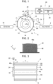
- Fig. 1 is a schematic view of a filter rod manufacturing machine.
- the filter rod manufacturing machine includes a roll-up section 2 and a conveyance section 4.
- a filter material formed from a filter fiber bundle such as acetate tow
- a raw-material rod is wrapped with an inner plug wrapper to form a continuous raw-material rod, and the raw-material rod is cut to manufacture filter rods FR.
- the raw-material rod may be formed by embedding a capsule into the filter material, adding activated carbon particles to the filter material, or adding particles of a hydrotalcite compound to the filter material.
- the filter material may be a filler in which a nonwoven fabric is folded, or a filler in which a paper web is gathered.
- Each filter rod FR manufactured by the roll-up section 2 is conveyed to the conveyance section 4.
- a drum row in which a plurality of rotatable conveyance drums are arranged in a row is disposed.
- Fig. 1 shows only one conveyance drum 6 in the drum row.
- the conveyance drum 6 includes a cylindrical core 10 in whose interior a suction source 8 is disposed, and a drum shell 12 that covers the cylindrical core 10.
- the drum shell 12 rotates around a rotational axis Ra as a center with respect to the cylindrical core 10.
- a plurality of holding grooves 14 that hold the filter rods FR are formed in an outer peripheral surface of the drum shell 12 along a peripheral direction Z.
- a suction pressure from the suction source 8 is applied to each holding groove 14.
- the filter rods FR are held by the holding grooves 14 in the outer peripheral surface of the drum shell 12 by the suction pressure of the suction source 8. Therefore, each filter rod FR is conveyed along the peripheral direction Z of the conveyance drum 6 as the drum shell 12 rotates.
- the filter rods FR on the conveyance drum 6 are conveyed while successively being transferred onto an adjacent conveyance drum on a downstream side in the drum row, and then are supplied to a next section 16.
- the filter rods FR are processed in a next step.
- the filter rods FR are canned in the next section 16 and conveyed to an apparatus of the next step, or are subjected to filter attachment processing in the next section 16.
- the filter attachment processing after the filter rods FR are connected to rods, which become flavor elements or tubular elements, through tipping paper, they are cut and become filter elements that constitute a flavor inhalation article.
- the inspection apparatus 20 for the filter rods FR is disposed at the conveyance section 4.
- the inspection apparatus 20 includes a camera 22, an illuminating device 24, a sensor 26, and a control unit 28.
- the control unit 28 includes an image processing unit 30 and a determination unit 32.
- the camera 22 and the sensor 26 are electrically connected to the control unit 28.
- the illuminating device 24 is, for example, an LED illuminating device of white light, and electrical power is supplied thereto by a power source 34.
- the camera 22 captures an image of an end portion 40 of a filter rod FR from a radial direction X orthogonal to the axial direction Y of the filter rod FR.
- An end surface 40a of the end portion 40 is shown on a near side in Fig. 1 .
- the sensor 26 detects a sending of the filter rod FR into the conveyance section 4, and outputs an imaging start signal to the control unit 28.
- the camera 22 receives the imaging start signal and captures the image of the end portion 40 at a timing in which the filter rod FR to be inspected that has been sent into the conveyance section 4 is conveyed to an imaging position P.
- the illuminating device 24 illuminates the end portion 40 in an illumination direction (shown by an alternate long and two short dash line) that faces the imaging direction (shown by an alternate long and short dash line) of the camera 22 across the end portion 40.
- the illuminating device 24 may be electrically connected to the control unit 28, or may be provided with a display unit (not shown) that displays the captured image captured by the camera 22.
- Fig. 2 shows an actual captured image captured by the camera 22.
- the image processing unit 30 processes the captured image and detects shading 42 of the end portion 40.
- portions corresponding to the end portion 40 and the end surface 40a in the shading 42 are indicated by the same reference numerals. This also applies to subsequent figures of captured images.
- the end portion 40 When a filter rod FR is normal, as shown in Fig. 2 , in a monochromatic image captured by the camera 22, the end portion 40 is detected as the shading 42 that is black and rectangular in an orientation in which an up-down direction is the axial direction Y of the end portion 40 and a left-right direction is the radial direction X of the end portion 40.
- the end surface 40a of the end portion 40 appears as a substantially straight boundary in an upper end of the shading 42.
- Fig. 3 is a side view of a conveyance drum 6.
- each filter rod FR protruding to an outer side of the drum shell 12 in the direction of the rotational axis Ra, each filter rod FR is held by the corresponding holding groove 14 of the drum shell 12. That is, the length of each filter rod FR in the axial direction Y is larger than the length of the drum shell 12 in the direction of the rotational axis Ra.
- the illuminating device 24 is fixed to an outer peripheral surface of the cylindrical core 10 that is positioned across the end portion 40.
- the camera 22 is fixed directly above the imaging position P that is situated above the illuminating device 24. Therefore, the camera 22 is capable of capturing an image of the end portion 40 from the radial direction X and the shading 42 appears in the captured image.
- the determination unit 32 determines the quality of a filter rod FR based on the shading 42 detected by the image processing unit 30.
- Fig. 4 is an inspection flowchart of an inspection by the inspection apparatus 20.
- the sensor 26 detects a sending of the filter rod FR into the conveyance section 4, and outputs an imaging start signal to the control unit 28 (filter rod detection step S1).
- the camera 22 receives the imaging start signal through the control unit 28, and, at a timing in which the filter rod FR to be inspected that has been sent into the conveyance section 4 is conveyed to the imaging position P, captures an image of the end portion 40 of the filter rod FR in the radial direction Y, and transmits captured image data to the image processing unit 30 (imaging step S2).
- the illuminating device 24 illuminates the end portion 40 in the illumination direction that faces the imaging direction of the camera 22 across the end portion 40 (illumination step S3).
- the image processing unit 30 processes the captured image transmitted from the camera 22 and detects the shading 42 of the end portion 40 (image processing step S4).
- the determination unit 32 determines the quality of the filter rod FR based on the shading 42 detected by the image processing unit 30 (determination step S5).
- Fig. 5 is a diagram for describing steps S41 to S45 and steps S51 to S54 of the inspection flowchart.
- step S41 an area S of the shading 42 is calculated and the process proceeds to step S51.
- step S51 it is determined whether or not the area S of the shading 42 is greater than or equal to a predetermined first threshold value T1.
- a predetermined first threshold value T1 When the determination result is Yes and S ⁇ T1 holds, it is determined that the filter rod FR properly exists at the imaging position P and that the filter rod FR can be inspected, and the process proceeds to step S42.
- the determination result in step S51 is No and S ⁇ T1 does not hold, that is, when the area S of the shading 42 becomes less than the first threshold value T1, there may be a problem in the capturing of the image of the end portion 40.
- the filter rod FR that is held by the drum shell 12 may be inclined, or the imaging timing of the camera 22 may be deviated and the image of the end portion 40 may not be properly captured. In this case, the process proceeds to step S52 and an output is made that the filter rod FR cannot be properly inspected and the inspection of the filter rod FR ends.
- step S42 two first edges E1 that are positioned on respective sides of the shading 42 in the radial direction X are detected.
- step S43 a first inspection region A1 that is defined by a region extending from inner sides of the two respective first edges E1 in the radial direction X of the shading 42 to the center of the shading 42 and including an upper end of the shading 42 in the axial direction Y is set.
- step S44 in the first inspection regionAl, a plurality of second edges E2 that are positioned on the upper end of the shading 42 in the axial direction Y are detected with a predetermined interval d existing in the radial direction X.
- step S45 an imaginary straight line L obtained by subjecting each second edge E2 to approximation linear processing is formed, and the process proceeds to step S53.
- step S53 the quality of the filter rod FR is determined based on the imaginary straight line L. Specifically, it is determined whether or not a standard deviation SD of a displacement amount w between the imaginary straight line L and each second edge E2 in the axial direction Y exceeds a predetermined second threshold value T2.
- a portion indicated by reference numeral 44; this also applies below
- a foreign substance such as a glue residue
- step S58 an output is made that the filter rod FR is defective, and the inspection ends.
- the defective filter rod FR is eliminated from a conveyance path of the conveyance section 4. This also applies in the description below.
- the detection result of step S53 is No and SD > T2 does not hold, that is, when the standard deviation SD of the displacement amount w between the imaginary straight line L and each second edge E2 in the axial direction Y becomes less than the second threshold value T2, the process proceeds to step S54.
- Fig. 6 is a diagram for describing steps S46 and S47 and step S55 of the inspection flowchart.
- a second inspection region A2 that is defined by a region extending to outer sides of the two respective first edges E1 in the radial direction X of the shading 42 and situated on an upper side of the imaginary straight line L in the axial direction Y is set.
- the imaginary straight line L extends in the radial direction X, and coincides with a lower end frame of the second inspection region A2.
- step S5 the quality of the filter rod FR is determined based on the second inspection region A2. Specifically, after setting the second inspection region A2 in step S46, the process proceeds to step S47, and, in step S47, the second inspection region A2 is subjected to binary black-and-white reversal processing.
- Fig. 7 shows a captured image after the binary black-and-white reversal processing when the end portion 40 is normal.
- step S55 it is determined whether or not one or more white regions AW formed in the second inspection region A2 by the binary black-and-white reversal processing exist and whether or not an area Sw of the white region AW is greater than or equal to a predetermined fourth threshold value T4.
- Fig. 8 shows a captured image after the binary black-and-white reversal processing when the foreign substance 44, such as a glue residue, is stuck in the end surface 40a. In the captured image, the foreign substance 44 appears clearly as the white region AW.
- step S48 upon terminating the binary black-and-white reversal processing performed in step S47 and restoring the second inspection region A2 to the original state, the second inspection region A2 is divided into a plurality of division regions AD, and the density of the color of each division region AD, in other words, the shade of black or gray is detected.
- step S56 it is determined whether a change rate Rv of the density of the color of each division region AD is greater than or equal to a predetermined fifth threshold value T5. Specifically, the change rate Rv of a particular division region AD is compared with the change rates Rv of the densities of the colors of three adjacent division regions AD in the radial direction X, the axial direction Y, or an oblique direction of the particular division region AD.
- the determination result is Yes and Rv ⁇ T5 holds, since it is supposed that the foreign substance 44, such as a glue residue, exists in the end surface 40a, the process proceeds to step S58 and an output is made that the filter rod FR is defective, and the inspection ends.
- the inspection apparatus 20 of the embodiment inspects the filter rod FR that becomes a filter element of a flavor inhalation article during a conveyance process at the conveyance section 4.
- the illuminating device 24 illuminates the end portion 40 in the illumination direction that faces the imaging direction of the camera 22 across the end portion 40, as a result of which it is possible to easily and reliably detect by the shading 42 of the end portion 40 that the foreign substance 44, such as a glue residue, is stuck in or adheres to the end surface 40a of the filter rod FR.
- the camera 22 receives an imaging start signal output from the sensor 26, the camera 22 captures an image of the end portion 40 at a timing in which the filter rod FR to be inspected that has been sent into the conveyance section 4 is conveyed to the imaging position P. Therefore, it is possible to reliably inspect filter rods FR that are successively sent to the conveyance section 4 without omitting any filter rod FR.
- each filter rod FR With the end portion 40 of each filter rod FR protruding to the outer side of the drum shell 12 in the direction of the rotational axis Ra, each filter rod FR is held by the outer peripheral surface of the drum shell 12, and the illuminating device 24 is fixed to the outer peripheral surface of the cylindrical core 10 across the end portion 40. Therefore, in the conveyance drum 6 that is disposed at the conveyance section 4, it is possible to reliably inspect the end surface 40a of each end portion 40 without producing blind spots of inspection at the end portion 40 of each filter rod FR that is being conveyed.
- the determination unit 32 determines that the filter rod FR properly exists at the imaging position P and that the filter rod FR can be inspected. Therefore, a case in which the inspection cannot be properly performed due to inclination of the filter rod FR at the time of the inspection or occurrence of a deviation in the imaging timing is previously eliminated. Consequently, it is possible to further improve inspection precision and inspection efficiency of the filter rod FR.
- the image processing unit 30 detects two first edges E1 of a captured image, sets the first inspection regionAl, and forms the imaginary straight line L. Further, in the determination step S5, the determination unit 32 determines the quality of a filter rod FR based on the imaginary straight line L.
- the filter rod FR is obtained by, after forming a raw-material rod by rolling up a filter fiber bundle into a rod shape, wrapping the raw-material rod with an inner plug wrapper and cutting the raw-material rod.
- a cut end of the inner plug wrapper protrudes slightly from the end surface 40a of the filter rod FR.
- the first inspection region A1 it is possible to prevent the cut end of the inner plug wrapper from being erroneously recognized as the foreign substance 44 existing in the end surface 40a. Therefore, it is possible to further improve inspection precision and inspection efficiency of the filter rod FR.
- the determination unit 32 determines that the filter rod FR is defective. Therefore, even when a plurality of foreign substances 44 intermittently exist in the end surface 40a, since it is possible to detect unacceptably large foreign substances 44, it is possible to further improve inspection precision and inspection efficiency of the filter rod FR.
- the determination unit 32 determines that the filter rod FR is defective. Therefore, even when a plurality of foreign substances 44 intermittently exist in the end surface 40a, it is possible to detect unacceptably large foreign substances 44 with even higher precision.
- the image processing unit 30 sets the second inspection region A2 in a captured image. Further, in the determination step S5, the determination unit 32 determines the quality of the filter rod FR based on the second inspection region A2. Therefore, it is possible to efficiently detect a foreign substance 44 that protrudes toward the region extending to the outer sides of the two respective first edges E1 in the radial direction X of the shading 42 and including the upper side of the imaginary straight line L in the axial direction Y, that is, the region existing on an outer side and an upper side of the first inspection region A 1 from the end surface 40a.
- the image processing unit 30 performs binary black-and-white reversal processing on the second inspection region A2. Further, in the determination step S5, when one or more white regions AW formed in the second inspection region A2 by the binary black-and-white reversal processing exist and the area Sw of the white region AW becomes greater than or equal to the fourth threshold value T4, the determination unit 32 determines that the filter rod FR is defective. Since the foreign substance 44 appears clearly as the white region AW, it is possible to further improve inspection precision and inspection efficiency of the filter rod FR.
- the image processing unit 30 divides the second inspection region A2 into a plurality of division regions AD and detects the density of the color of each division region AD. Further, in the determination step S5, when the change rate Rv of the density of the color of each division region AD becomes greater than or equal to the fifth threshold value T5, the determination unit 32 determines that the filter rod FR is defective. Therefore, even if the foreign substance 44 is one that protrudes in a posture or orientation in which the shading 42 is unlikely to occur from the end surface 40a or the shade of the shading 42 is light, it is possible to detect the difference between the densities of the colors. Thus, it is possible to further improve inspection precision and inspection efficiency of the filter rod FR.
- each step that constitutes the image processing step S4 and each step that constitutes the determination step S5 need not be necessarily performed in the order described in the embodiment.
- each step has the operational effect described above, not all of the steps need to be performed.
- the determination of step S56 may be performed before the determination of step S55, or only one of steps S55 and S56 may be performed.
- step S54 may be performed before the determination of step S53, or only one of the steps S53 and S54 may be performed.
Landscapes
- Health & Medical Sciences (AREA)
- General Health & Medical Sciences (AREA)
- Toxicology (AREA)
- Investigating Materials By The Use Of Optical Means Adapted For Particular Applications (AREA)
Abstract
Description
- The present invention relates to an inspection apparatus and an inspection method for a filter rod, and, specifically, relates to an inspection apparatus and an inspection method, which, in a conveyance process, inspect a filter rod that becomes a filter element of a flavor inhalation article.
-
PTL 1 discloses an inspection apparatus for a filter rod. The inspection apparatus includes a plurality of light sources that emit light beams of different wavelength distributions, an adjusting unit that forms inspection light from the light beams emitted from the respective light sources, an illuminating unit that illuminates the filter rod with the inspection light formed by the adjusting unit, a photodetector that receives measurement light obtained as a result of the inspection light applied from the illuminating unit acting upon the filter rod, and a determination unit that determines the quality of the filter rod based on the measurement light received by the photodetector. The adjusting unit adjusts the color of the inspection light by mixing the light beams emitted from the respective light sources. -
PTL 1 also discloses a filter rod manufacturing machine including the inspection apparatus above. The manufacturing machine includes a conveyance drum that conveys the filter rod, and the conveyance drum includes a cylindrical core in whose interior a suction source and the illuminating unit are disposed, and a drum shell that covers the cylindrical core and that is rotatably disposed with respect to the cylindrical core. The cylindrical core has a communication port that causes the suction source and the drum shell to communicate with each other in a peripheral direction thereof and a first illumination port at which the illuminating unit is positioned. - The drum shell has a plurality of holding grooves that are arranged with an interval therebetween in a peripheral direction thereof and that each hold a filter rod, a suction hole that communicates with the communication port as the drum shell rotates, and a second illumination port that opens into a bottom wall of each holding groove. By, as the drum shell rotates, positioning each filter rod with respect to the suction hole at each holding groove such that the second illumination port overlaps the first illumination port, the filter rods held by the holding grooves are illuminated with the inspection light.
- The suction hole of the manufacturing machine is used as a second illumination port of the inspection apparatus, and the second illumination port is formed into a long hole whose length is greater than or equal to the length of each filter rod. This makes it possible to perform good inspection of each filter rod independently of the type, in particular, the color of each filter rod to be inspected, and without requiring a complicated apparatus structure, such as an apparatus structure involving complicated threshold setting or complicated spectral analysis.
- PTL 1: International Publication No.
2019/077665 - A filter rod is obtained by, for example, after forming a raw-material rod by rolling up a filter fiber bundle, such as acetate tow, into a rod shape, wrapping the raw-material rod with an inner plug wrapper and cutting the raw-material rod. In a process of conveying the filter rod to the conveyance section, glue used to wrap the filter rod adheres to a conveyance path and the glue accumulates and hardens, as a result of which the glue may grow into a needle-shaped glue residue.
- In the process of conveying the filter rod, the needle-shaped glue residue may get stuck into or adhere to an end surface of the filter rod that is oriented in a conveyance direction. When the needle-shaped glue residue gets stuck into or adheres to the end surface of the filter rod, the filter rod becomes a defective product, and thus a filter element used in a flavor inhalation article (may not contain a tobacco raw material) becomes a defective product. Since the defective product needs to be eliminated in the next step and subsequent steps, when the filter element and thus the flavor inhalation article have their productivity reduced, and become products without being eliminated, the quality of the flavor inhalation article is reduced and a user may no longer have confidence in the products.
- In
PTL 1, although the second illumination port is formed into a long hole whose length is greater than or equal to the length of the filter rod, since the suction hole opens into the bottom wall of each holding groove that holds a corresponding filter rod, the width of the suction hole, that is, the width of the second illumination port is smaller than the diameter of the filter rod. Since the inspection light that is applied from the illuminating unit illuminates the filter rod by passing through the second illumination port, a radial-direction part of the filter rod protruding from the width of the second illumination port and the end portion of the filter rod are positioned in blind spots of an inspection region, and cannot be inspected. - Therefore, even when the glue residue gets stuck into or adheres to the end surface of the filter rod, such a foreign substance cannot be detected, and the filter rod is not eliminated as a defective product. Thus, capturing an image of the end surface of the filter rod from a forward side and inspecting the end surface of the filter rod may be considered. However, even when a foreign substance gets stuck into or adheres to the end surface of the filter rod, when an image of the end surface of the filter rod is captured from the forward side, the needle-shaped glue residue may be image-recognized only as almost a point, and thus is difficult to be identified as a glue residue.
- Since the color of the end surface of the filter rod and the color of the glue residue are colors that are substantially close to white, even if, as with the adjusting unit of the inspection apparatus of
PTL 1, the color of the inspection light is adjusted by mixing the colors of the light beams emitted from the respective light sources, the glue residue is difficult to identify. Therefore, there is a demand for efficiently detecting a defective product by inspection at the stage of the filter rod to eliminate the filter rod, the defective product being damaged by a foreign substance, such as a glue residue, getting stuck into or adhering to the end surface of the filter rod, or the end surface of the filter rod coming into contact with a foreign substance, such as a glue residue. - The present invention has been made in view of such problems, and it is an object of the present invention to provide an inspection apparatus and an inspection method for a filter rod, which are capable of efficiently inspecting the filter rod and improving the quality of the filter rod.
- To this end, an inspection apparatus for a filter rod according to an aspect is an inspection apparatus that inspects at a conveyance section the filter rod that becomes a filter element of a flavor inhalation article, and that includes a camera that captures an image of an end portion of the filter rod from a radial direction orthogonal to an axial direction of the filter rod, an illuminating device that illuminates the end portion in an illumination direction that faces an imaging direction of the camera across the end portion, an image processing unit that processes the image captured by the camera so as to detect shading of the end portion, and a determination unit that determines a quality of the filter rod based on the shading detected by the image processing unit.
- An inspection method for a filter rod according to another aspect is an inspection method of inspecting at a conveyance section the filter rod that becomes a filter element of a flavor inhalation article, and the inspection method includes an imaging step of capturing an image of an end portion of the filter rod from a radial direction orthogonal to an axial direction of the filter rod; an illumination step of illuminating the end portion in an illumination direction that faces an imaging direction in the imaging step across the end portion; an image processing step of processing the image captured in the imaging step so as to detect shading of the end portion; and a determination step of determining a quality of the filter rod based on the shading detected in the image processing step.
- It is possible to efficiently inspect a filter rod and to improve the quality of the filter rod.
-
- [
Fig. 1] Fig. 1 is a schematic view of a filter rod manufacturing machine. - [
Fig. 2] Fig. 2 shows an actual captured image captured by a camera. - [
Fig. 3] Fig. 3 is a side view of a conveyance drum. - [
Fig. 4] Fig. 4 is an inspection flowchart of an inspection by an inspection apparatus. - [
Fig. 5] Fig. 5 is a diagram for describing steps S41 to S45 and steps S51 to S54 of the inspection flowchart. - [
Fig. 6] Fig. 6 is a diagram for describing steps S46 and S47 and step S55 of the inspection flow chart. - [
Fig. 7] Fig. 7 shows a captured image after binary black-and-white reversal processing when an end portion is normal. - [
Fig. 8] Fig. 8 shows a captured image after binary black-and-white reversal processing when a foreign substance is stuck in an end surface. - [
Fig. 9] Fig. 9 is a diagram for illustrating steps S48 and S56 of the inspection flowchart. -
Fig. 1 is a schematic view of a filter rod manufacturing machine. The filter rod manufacturing machine includes a roll-upsection 2 and aconveyance section 4. In the roll-upsection 2, for example, a filter material formed from a filter fiber bundle, such as acetate tow, is rolled up into a rod shape. Then, a raw-material rod is wrapped with an inner plug wrapper to form a continuous raw-material rod, and the raw-material rod is cut to manufacture filter rods FR. - Note that it is possible to line up by using a combiner a plurality of types of raw-material rods cut out from different filter materials and form a continuous body, and wrap the continuous body with an outer plug wrapper and connect the continuous body, to thereby form the filter rods FR. The raw-material rod may be formed by embedding a capsule into the filter material, adding activated carbon particles to the filter material, or adding particles of a hydrotalcite compound to the filter material. The filter material may be a filler in which a nonwoven fabric is folded, or a filler in which a paper web is gathered.
- Each filter rod FR manufactured by the roll-up
section 2 is conveyed to theconveyance section 4. In theconveyance section 4, a drum row in which a plurality of rotatable conveyance drums are arranged in a row is disposed.Fig. 1 shows only oneconveyance drum 6 in the drum row. Theconveyance drum 6 includes acylindrical core 10 in whose interior asuction source 8 is disposed, and adrum shell 12 that covers thecylindrical core 10. Thedrum shell 12 rotates around a rotational axis Ra as a center with respect to thecylindrical core 10. - A plurality of
holding grooves 14 that hold the filter rods FR are formed in an outer peripheral surface of thedrum shell 12 along a peripheral direction Z. A suction pressure from thesuction source 8 is applied to eachholding groove 14. In an orientation in which an axial direction Y (seeFig. 2 ) of each filter rod FR is parallel to the rotational axis Ra, the filter rods FR are held by theholding grooves 14 in the outer peripheral surface of thedrum shell 12 by the suction pressure of thesuction source 8. Therefore, each filter rod FR is conveyed along the peripheral direction Z of theconveyance drum 6 as thedrum shell 12 rotates. - The filter rods FR on the
conveyance drum 6 are conveyed while successively being transferred onto an adjacent conveyance drum on a downstream side in the drum row, and then are supplied to anext section 16. In thenext section 16, the filter rods FR are processed in a next step. For example, the filter rods FR are canned in thenext section 16 and conveyed to an apparatus of the next step, or are subjected to filter attachment processing in thenext section 16. In the filter attachment processing, after the filter rods FR are connected to rods, which become flavor elements or tubular elements, through tipping paper, they are cut and become filter elements that constitute a flavor inhalation article. - An
inspection apparatus 20 for the filter rods FR is disposed at theconveyance section 4. Theinspection apparatus 20 includes acamera 22, an illuminatingdevice 24, asensor 26, and acontrol unit 28. Thecontrol unit 28 includes animage processing unit 30 and adetermination unit 32. Thecamera 22 and thesensor 26 are electrically connected to thecontrol unit 28. The illuminatingdevice 24 is, for example, an LED illuminating device of white light, and electrical power is supplied thereto by apower source 34. - The
camera 22 captures an image of anend portion 40 of a filter rod FR from a radial direction X orthogonal to the axial direction Y of the filter rod FR. Anend surface 40a of theend portion 40 is shown on a near side inFig. 1 . Thesensor 26 detects a sending of the filter rod FR into theconveyance section 4, and outputs an imaging start signal to thecontrol unit 28. Thecamera 22 receives the imaging start signal and captures the image of theend portion 40 at a timing in which the filter rod FR to be inspected that has been sent into theconveyance section 4 is conveyed to an imaging position P. - The illuminating
device 24 illuminates theend portion 40 in an illumination direction (shown by an alternate long and two short dash line) that faces the imaging direction (shown by an alternate long and short dash line) of thecamera 22 across theend portion 40. Note that the illuminatingdevice 24 may be electrically connected to thecontrol unit 28, or may be provided with a display unit (not shown) that displays the captured image captured by thecamera 22. -
Fig. 2 shows an actual captured image captured by thecamera 22. Theimage processing unit 30 processes the captured image and detects shading 42 of theend portion 40. In the captured image shown inFig. 2 , portions corresponding to theend portion 40 and theend surface 40a in theshading 42 are indicated by the same reference numerals. This also applies to subsequent figures of captured images. - When a filter rod FR is normal, as shown in
Fig. 2 , in a monochromatic image captured by thecamera 22, theend portion 40 is detected as theshading 42 that is black and rectangular in an orientation in which an up-down direction is the axial direction Y of theend portion 40 and a left-right direction is the radial direction X of theend portion 40. Theend surface 40a of theend portion 40 appears as a substantially straight boundary in an upper end of theshading 42. -
Fig. 3 is a side view of aconveyance drum 6. With theend portion 40 of each filter rod FR protruding to an outer side of thedrum shell 12 in the direction of the rotational axis Ra, each filter rod FR is held by the corresponding holdinggroove 14 of thedrum shell 12. That is, the length of each filter rod FR in the axial direction Y is larger than the length of thedrum shell 12 in the direction of the rotational axis Ra. The illuminatingdevice 24 is fixed to an outer peripheral surface of thecylindrical core 10 that is positioned across theend portion 40. - By, for example, a bracket (not shown), the
camera 22 is fixed directly above the imaging position P that is situated above the illuminatingdevice 24. Therefore, thecamera 22 is capable of capturing an image of theend portion 40 from the radial direction X and theshading 42 appears in the captured image. Thedetermination unit 32 determines the quality of a filter rod FR based on theshading 42 detected by theimage processing unit 30. -
Fig. 4 is an inspection flowchart of an inspection by theinspection apparatus 20. When an inspection of a filter rod FR is started, thesensor 26 detects a sending of the filter rod FR into theconveyance section 4, and outputs an imaging start signal to the control unit 28 (filter rod detection step S1). Next, thecamera 22 receives the imaging start signal through thecontrol unit 28, and, at a timing in which the filter rod FR to be inspected that has been sent into theconveyance section 4 is conveyed to the imaging position P, captures an image of theend portion 40 of the filter rod FR in the radial direction Y, and transmits captured image data to the image processing unit 30 (imaging step S2). - At the same timing as the imaging step S2 or before this timing, the illuminating
device 24 illuminates theend portion 40 in the illumination direction that faces the imaging direction of thecamera 22 across the end portion 40 (illumination step S3). Next, theimage processing unit 30 processes the captured image transmitted from thecamera 22 and detects theshading 42 of the end portion 40 (image processing step S4). Next, thedetermination unit 32 determines the quality of the filter rod FR based on theshading 42 detected by the image processing unit 30 (determination step S5). - With reference to
Fig. 5 to Fig. 9 , steps S41 to S48 that constitute the image processing step S4 and steps S51 to s58 that constitute the determination step S5 are described in detail below.Fig. 5 is a diagram for describing steps S41 to S45 and steps S51 to S54 of the inspection flowchart. In step S41, an area S of theshading 42 is calculated and the process proceeds to step S51. - In step S51, it is determined whether or not the area S of the
shading 42 is greater than or equal to a predetermined first threshold value T1. When the determination result is Yes and S ≥ T1 holds, it is determined that the filter rod FR properly exists at the imaging position P and that the filter rod FR can be inspected, and the process proceeds to step S42. On the other hand, when the determination result in step S51 is No and S ≥ T1 does not hold, that is, when the area S of theshading 42 becomes less than the first threshold value T1, there may be a problem in the capturing of the image of theend portion 40. - Specifically, the filter rod FR that is held by the
drum shell 12 may be inclined, or the imaging timing of thecamera 22 may be deviated and the image of theend portion 40 may not be properly captured. In this case, the process proceeds to step S52 and an output is made that the filter rod FR cannot be properly inspected and the inspection of the filter rod FR ends. - In step S42, two first edges E1 that are positioned on respective sides of the
shading 42 in the radial direction X are detected. Next, in step S43, a first inspection region A1 that is defined by a region extending from inner sides of the two respective first edges E1 in the radial direction X of theshading 42 to the center of theshading 42 and including an upper end of theshading 42 in the axial direction Y is set. Next, in step S44, in the first inspection regionAl, a plurality of second edges E2 that are positioned on the upper end of theshading 42 in the axial direction Y are detected with a predetermined interval d existing in the radial direction X. - Next, in step S45, an imaginary straight line L obtained by subjecting each second edge E2 to approximation linear processing is formed, and the process proceeds to step S53. In step S53, the quality of the filter rod FR is determined based on the imaginary straight line L. Specifically, it is determined whether or not a standard deviation SD of a displacement amount w between the imaginary straight line L and each second edge E2 in the axial direction Y exceeds a predetermined second threshold value T2. When the determination result is Yes and SD > T2 holds, it is supposed that a portion (indicated by
reference numeral 44; this also applies below) corresponding to a foreign substance, such as a glue residue, exists in theend surface 40a of theend portion 40. - Therefore, the process proceeds to step S58 and an output is made that the filter rod FR is defective, and the inspection ends. When the inspection ends through step S58, the defective filter rod FR is eliminated from a conveyance path of the
conveyance section 4. This also applies in the description below. On the other hand, when the detection result of step S53 is No and SD > T2 does not hold, that is, when the standard deviation SD of the displacement amount w between the imaginary straight line L and each second edge E2 in the axial direction Y becomes less than the second threshold value T2, the process proceeds to step S54. - In step S54, it is determined whether or not an inclination angle α of the imaginary straight line L with respect to the radial direction X exceeds a predetermined third threshold value T3. When the determination result is Yes and α > T3 holds, it is supposed that a
foreign substance 44, such as a glue residue, exists in theend surface 40a. Therefore, the process proceeds to step s58 and an output is made that the filter rod FR is defective, and the inspection ends. On the other hand, when the determination result is No and α > T3 does not hold, that is, when the standard deviation SD of the displacement amount w between the imaginary straight line L and each second edge E2 in the axial direction Y becomes less than the second threshold value T2, the process proceeds to step S46. -
Fig. 6 is a diagram for describing steps S46 and S47 and step S55 of the inspection flowchart. In step S46, a second inspection region A2 that is defined by a region extending to outer sides of the two respective first edges E1 in the radial direction X of theshading 42 and situated on an upper side of the imaginary straight line L in the axial direction Y is set. Note that, for the sake of convenience of drawing of the figures and descriptions, inFig. 6 , the imaginary straight line L extends in the radial direction X, and coincides with a lower end frame of the second inspection region A2. - Next, in the determination step S5, the quality of the filter rod FR is determined based on the second inspection region A2. Specifically, after setting the second inspection region A2 in step S46, the process proceeds to step S47, and, in step S47, the second inspection region A2 is subjected to binary black-and-white reversal processing.
Fig. 7 shows a captured image after the binary black-and-white reversal processing when theend portion 40 is normal. Next, in step S55, it is determined whether or not one or more white regions AW formed in the second inspection region A2 by the binary black-and-white reversal processing exist and whether or not an area Sw of the white region AW is greater than or equal to a predetermined fourth threshold value T4. - When the determination result is Yes and, in the white region AW that exists, Sw ≥ T4 holds, since it is supposed that the
foreign substance 44, such as a glue residue, exists in theend surface 40a, the process proceeds to step S58 and an output is made that the filter rod FR is defective, and the inspection ends.Fig. 8 shows a captured image after the binary black-and-white reversal processing when theforeign substance 44, such as a glue residue, is stuck in theend surface 40a. In the captured image, theforeign substance 44 appears clearly as the white region AW. - On the other hand, when the determination result is No and Sw ≥ T4 does not hold, that is, even when the white region AW does not exist or when the area Sw becomes less than the fourth threshold value T4 even when the white region AW exists, the process proceeds to step S48.
Fig. 9 is a diagram for illustrating steps S48 and S56 in the inspection flowchart. In step S48, upon terminating the binary black-and-white reversal processing performed in step S47 and restoring the second inspection region A2 to the original state, the second inspection region A2 is divided into a plurality of division regions AD, and the density of the color of each division region AD, in other words, the shade of black or gray is detected. - Next, in step S56, it is determined whether a change rate Rv of the density of the color of each division region AD is greater than or equal to a predetermined fifth threshold value T5. Specifically, the change rate Rv of a particular division region AD is compared with the change rates Rv of the densities of the colors of three adjacent division regions AD in the radial direction X, the axial direction Y, or an oblique direction of the particular division region AD. When the determination result is Yes and Rv ≥ T5 holds, since it is supposed that the
foreign substance 44, such as a glue residue, exists in theend surface 40a, the process proceeds to step S58 and an output is made that the filter rod FR is defective, and the inspection ends. - On the other hand, when the determination result is No and Rv ≥ T5 does not hold, that is, when the change rate Rv of the density of the color of each division region AD becomes less than the fifth threshold value T5, the process proceeds to step S57 and output is made that the filter rod FR is normal, and the inspection ends. In this way, each time the
sensor 26 detects a filter rod FR, the inspection of each filter rod FR that is being conveyed is successively performed in accordance with the inspection flowchart. - As described above, the
inspection apparatus 20 of the embodiment inspects the filter rod FR that becomes a filter element of a flavor inhalation article during a conveyance process at theconveyance section 4. The illuminatingdevice 24 illuminates theend portion 40 in the illumination direction that faces the imaging direction of thecamera 22 across theend portion 40, as a result of which it is possible to easily and reliably detect by theshading 42 of theend portion 40 that theforeign substance 44, such as a glue residue, is stuck in or adheres to theend surface 40a of the filter rod FR. - Therefore, at the stage of the filter rod FR, it is possible to detect and reliably eliminate the defective filter rod FR, and to improve inspection efficiency and the quality of the filter rod FR. More specifically, when, in the filter rod detection step S1, the
camera 22 receives an imaging start signal output from thesensor 26, thecamera 22 captures an image of theend portion 40 at a timing in which the filter rod FR to be inspected that has been sent into theconveyance section 4 is conveyed to the imaging position P. Therefore, it is possible to reliably inspect filter rods FR that are successively sent to theconveyance section 4 without omitting any filter rod FR. - With the
end portion 40 of each filter rod FR protruding to the outer side of thedrum shell 12 in the direction of the rotational axis Ra, each filter rod FR is held by the outer peripheral surface of thedrum shell 12, and the illuminatingdevice 24 is fixed to the outer peripheral surface of thecylindrical core 10 across theend portion 40. Therefore, in theconveyance drum 6 that is disposed at theconveyance section 4, it is possible to reliably inspect theend surface 40a of eachend portion 40 without producing blind spots of inspection at theend portion 40 of each filter rod FR that is being conveyed. - In the determination step S5, when the area S of the
shading 42 becomes greater than or equal to the first threshold value T1, thedetermination unit 32 determines that the filter rod FR properly exists at the imaging position P and that the filter rod FR can be inspected. Therefore, a case in which the inspection cannot be properly performed due to inclination of the filter rod FR at the time of the inspection or occurrence of a deviation in the imaging timing is previously eliminated. Consequently, it is possible to further improve inspection precision and inspection efficiency of the filter rod FR. - In the image processing step S4, the
image processing unit 30 detects two first edges E1 of a captured image, sets the first inspection regionAl, and forms the imaginary straight line L. Further, in the determination step S5, thedetermination unit 32 determines the quality of a filter rod FR based on the imaginary straight line L. Here, the filter rod FR is obtained by, after forming a raw-material rod by rolling up a filter fiber bundle into a rod shape, wrapping the raw-material rod with an inner plug wrapper and cutting the raw-material rod. - Due to the cutting of the raw-material rod, a cut end of the inner plug wrapper protrudes slightly from the
end surface 40a of the filter rod FR. However, by inspecting the first inspection region A1, it is possible to prevent the cut end of the inner plug wrapper from being erroneously recognized as theforeign substance 44 existing in theend surface 40a. Therefore, it is possible to further improve inspection precision and inspection efficiency of the filter rod FR. - In the determination step S5, when the standard deviation SD of the displacement amount w between the imaginary straight line L and each second edge E2 in the axial direction Y exceeds the second threshold value T2, the
determination unit 32 determines that the filter rod FR is defective. Therefore, even when a plurality offoreign substances 44 intermittently exist in theend surface 40a, since it is possible to detect unacceptably largeforeign substances 44, it is possible to further improve inspection precision and inspection efficiency of the filter rod FR. - In the determination step S5, when the inclination angle α of the imaginary straight line L with respect to the radial direction X exceeds the third threshold value T3, the
determination unit 32 determines that the filter rod FR is defective. Therefore, even when a plurality offoreign substances 44 intermittently exist in theend surface 40a, it is possible to detect unacceptably largeforeign substances 44 with even higher precision. - In the image processing step S4, the
image processing unit 30 sets the second inspection region A2 in a captured image. Further, in the determination step S5, thedetermination unit 32 determines the quality of the filter rod FR based on the second inspection region A2. Therefore, it is possible to efficiently detect aforeign substance 44 that protrudes toward the region extending to the outer sides of the two respective first edges E1 in the radial direction X of theshading 42 and including the upper side of the imaginary straight line L in the axial direction Y, that is, the region existing on an outer side and an upper side of the firstinspection region A 1 from theend surface 40a. - In the image processing step S4, the
image processing unit 30 performs binary black-and-white reversal processing on the second inspection region A2. Further, in the determination step S5, when one or more white regions AW formed in the second inspection region A2 by the binary black-and-white reversal processing exist and the area Sw of the white region AW becomes greater than or equal to the fourth threshold value T4, thedetermination unit 32 determines that the filter rod FR is defective. Since theforeign substance 44 appears clearly as the white region AW, it is possible to further improve inspection precision and inspection efficiency of the filter rod FR. - In the image processing step S4, the
image processing unit 30 divides the second inspection region A2 into a plurality of division regions AD and detects the density of the color of each division region AD. Further, in the determination step S5, when the change rate Rv of the density of the color of each division region AD becomes greater than or equal to the fifth threshold value T5, thedetermination unit 32 determines that the filter rod FR is defective. Therefore, even if theforeign substance 44 is one that protrudes in a posture or orientation in which theshading 42 is unlikely to occur from theend surface 40a or the shade of theshading 42 is light, it is possible to detect the difference between the densities of the colors. Thus, it is possible to further improve inspection precision and inspection efficiency of the filter rod FR. - Although the description of the embodiment above will be ended, the embodiment above is not limitative, and various changes can be made within a scope that does not depart from the spirit of the present invention. For example, in the embodiment, as shown in the inspection flowchart of
Fig. 4 , by performing each determination in stages, it is possible to improve inspection precision and inspection efficiency of the filter rod FR. - However, each step that constitutes the image processing step S4 and each step that constitutes the determination step S5 need not be necessarily performed in the order described in the embodiment. In addition, since each step has the operational effect described above, not all of the steps need to be performed. For example, the determination of step S56 may be performed before the determination of step S55, or only one of steps S55 and S56 may be performed.
- Alternatively, the determination of step S54 may be performed before the determination of step S53, or only one of the steps S53 and S54 may be performed.
-
- 4 conveyance section
- 6 conveyance drum
- 8 suction source
- 10 cylindrical core
- 12 drum shell
- 20 inspection apparatus
- 22 camera
- 24 illuminating device
- 26 sensor
- 30 image processing unit
- 32 determination unit
- 40 end portion
- 42 shading
- A1 first inspection region
- A2 second inspection region
- AW white region
- AD division region
- d predetermined interval
- E1 first edge
- E2 second edge
- FR filter rod
- L imaginary straight line
- P imaging position
- Ra rotational axis
- S area of shading
- SD standard deviation
- Sw area of white region
- T1 first threshold value
- T2 second threshold value
- T3 third threshold value
- T4 fourth threshold value
- T5 fifth threshold value
- w displacement amount
- X radial direction
- Y axial direction
- α inclination angle
- S1 filter rod detection step
- S2 imaging step
- S3 illumination step
- S4 image processing step
- S5 determination step
Claims (19)
- An inspection apparatus for a filter rod that inspects at a conveyance section the filter rod that becomes a filter element of a flavor inhalation article, the inspection apparatus comprising:a camera that captures an image of an end portion of the filter rod from a radial direction orthogonal to an axial direction of the filter rod;an illuminating device that illuminates the end portion in an illumination direction that faces an imaging direction of the camera across the end portion;an image processing unit that processes the image captured by the camera so as to detect shading of the end portion; anda determination unit that determines a quality of the filter rod based on the shading detected by the image processing unit.
- The inspection apparatus for the filter rod according to claim 1, comprising:a sensor that detects a sending of the filter rod into the conveyance section and outputs an imaging start signal,wherein the camera receives the imaging start signal and captures the image of the end portion at a timing in which the filter rod to be inspected that has been sent into the conveyance section is conveyed to an imaging position.
- The inspection apparatus for the filter rod according to claim 2,wherein the conveyance section includes a conveyance drum that conveys the filter rod,wherein the conveyance drum includesa cylindrical core in whose interior a suction source is disposed, anda drum shell that covers the cylindrical core, that is disposed so as to be rotatable around a rotational axis as a center with respect to the cylindrical core, and that, in an orientation in which the axial direction is parallel to the rotational axis, holds the filter rod at an outer peripheral surface of the drum shell by a suction pressure of the suction source,wherein, with the end portion protruding to an outer side of the drum shell in a direction of the rotational axis, the filter rod is held at the outer peripheral surface of the drum shell, andwherein the illuminating device is fixed to an outer peripheral surface of the cylindrical core positioned across the end portion.
- The inspection apparatus for the filter rod according to claim 3,
wherein, when an area of the shading becomes greater than or equal to a predetermined first threshold value, the determination unit determines that the filter rod properly exists at the imaging position and that the filter rod is capable of being inspected. - The inspection apparatus for the filter rod according to claim 4,wherein, in the image that is captured, the image processing unit detects two first edges that are positioned on respective sides of the shading in the radial direction, sets a first inspection region that is defined by a region extending from inner sides of respective ones of the two first edges in the radial direction of the shading to a center of the shading and including an upper end of the shading in the axial direction, detects in the first inspection region a plurality of second edges that are positioned on the upper end of the shading in the axial direction with a predetermined interval existing in the radial direction, and forms an imaginary straight line obtained by subjecting each of the second edges to approximation linear processing, andwherein the determination unit determines the quality of the filter rod based on the imaginary straight line.
- The inspection apparatus for the filter rod according to claim 5,
wherein, when a standard deviation of a displacement amount between the imaginary straight line and each of the second edges in the axial direction exceeds a predetermined second threshold value, the determination unit determines that the filter rod is defective. - The inspection apparatus for the filter rod according to claim 5 or claim 6,
wherein, when an inclination angle of the imaginary straight line with respect to the radial direction exceeds a predetermined third threshold value, the determination unit determines that the filter rod is defective. - The inspection apparatus for the filter rod according to any one of claims 5 to 7,wherein, in the image that is captured, the image processing unit sets a second inspection region that is defined by a region extending to outer sides of respective ones of the two first edges in the radial direction of the shading and situated on an upper side of the imaginary straight line in the axial direction, andwherein the determination unit determines the quality of the filter rod based on the second inspection region.
- The inspection apparatus for the filter rod according to claim 8,wherein the image processing unit performs binary black-and-white reversal processing on the second inspection region, andwherein, when one or more white regions formed in the second inspection region by the binary black-and-white reversal processing exist and an area of the one or more white regions is greater than or equal to a predetermined fourth threshold value, the determination unit determines that the filter rod is defective.
- The inspection apparatus for the filter rod according to claim 8 or claim 9,wherein the image processing unit divides the second inspection region into a plurality of division regions and detects a density of a color of each of the division regions, andwherein, when a change rate of the density of the color of each of the division regions is greater than or equal to a predetermined fifth threshold value, the determination unit determines that the filter rod is defective.
- An inspection method for a filter rod of inspecting at a conveyance section the filter rod that becomes a filter element of a flavor inhalation article, the inspection method comprising:an imaging step of capturing an image of an end portion of the filter rod from a radial direction orthogonal to an axial direction of the filter rod;an illumination step of illuminating the end portion in an illumination direction that faces an imaging direction in the imaging step across the end portion;an image processing step of processing the image captured in the imaging step so as to detect shading of the end portion; anda determination step of determining a quality of the filter rod based on the shading detected in the image processing step.
- The inspection method for the filter rod according to claim 11, comprising:a filter rod detection step of detecting a sending of the filter rod into the conveyance section and outputting an imaging start signal,wherein, in the imaging step, the imaging start signal is received and the image of the end portion is captured at a timing in which the filter rod to be inspected that has been sent into the conveyance section is conveyed to an imaging position.
- The inspection method for the filter rod according to claim 12,
wherein, in the determination step, when an area of the shading becomes greater than or equal to a predetermined first threshold value, it is determined that the filter rod properly exists at the imaging position and that the filter rod is capable of being inspected. - The inspection method for the filter rod according to claim 13,wherein, in the image processing step, in the image that is captured, two first edges that are positioned on respective sides of the shading in the radial direction are detected; a first inspection region that is defined by a region extending from inner sides of respective ones of the two first edges in the radial direction of the shading to a center of the shading and including an upper end of the shading in the axial direction is set; in the first inspection region, a plurality of second edges that are positioned on the upper end of the shading in the axial direction with a predetermined interval existing in the radial direction are detected; and an imaginary straight line obtained by subjecting each of the second edges to approximation linear processing is formed, andwherein, in the determination step, the quality of the filter rod is determined based on the imaginary straight line.
- The inspection method for the filter rod according to claim 14,
wherein, in the determination step, when a standard deviation of a displacement amount between the imaginary straight line and each of the second edges in the axial direction exceeds a predetermined second threshold value, it is determined that the filter rod is defective. - The inspection method for the filter rod according to claim 14 or claim 15,
wherein, in the determination step, when an inclination angle of the imaginary straight line with respect to the radial direction exceeds a predetermined third threshold value, it is determined that the filter rod is defective. - The inspection method for the filter rod according to any one of claims 14 to 16,wherein, in the image processing step, in the image that is captured, a second inspection region that is defined by a region extending to outer sides of respective ones of the two first edges in the radial direction of the shading and situated on an upper side of the imaginary straight line in the axial direction is set, andwherein, in the determination step, the quality of the filter rod is determined based on the second inspection region.
- The inspection method for the filter rod according to claim 17,wherein, in the image processing step, binary black-and-white reversal processing is performed on the second inspection region, andwherein, in the determination step, when one or more white regions formed in the second inspection region by the binary black-and-white reversal processing exist and an area of the one or more white regions is greater than or equal to a predetermined fourth threshold value, it is determined that the filter rod is defective.
- The inspection method for the filter rod according to claim 17 to claim 18,wherein, in the image processing step, the second inspection region is divided into a plurality of division regions and a density of a color of each of the division regions is detected, andwherein, in the determination step, when a change rate of the density of the color of each of the division regions is greater than or equal to a predetermined fifth threshold value, it is determined that the filter rod is defective.
Applications Claiming Priority (1)
| Application Number | Priority Date | Filing Date | Title |
|---|---|---|---|
| PCT/JP2021/045135 WO2023105684A1 (en) | 2021-12-08 | 2021-12-08 | Inspection apparatus and inspection method for filter rod |
Publications (2)
| Publication Number | Publication Date |
|---|---|
| EP4445754A1 true EP4445754A1 (en) | 2024-10-16 |
| EP4445754A4 EP4445754A4 (en) | 2025-11-05 |
Family
ID=86729967
Family Applications (1)
| Application Number | Title | Priority Date | Filing Date |
|---|---|---|---|
| EP21967183.1A Pending EP4445754A4 (en) | 2021-12-08 | 2021-12-08 | INSPECTION DEVICE AND INSPECTION PROCEDURES FOR FILTER ROD |
Country Status (2)
| Country | Link |
|---|---|
| EP (1) | EP4445754A4 (en) |
| WO (1) | WO2023105684A1 (en) |
Family Cites Families (5)
| Publication number | Priority date | Publication date | Assignee | Title |
|---|---|---|---|---|
| US6169600B1 (en) * | 1998-11-20 | 2001-01-02 | Acuity Imaging, Llc | Cylindrical object surface inspection system |
| JP2002014050A (en) * | 2000-06-30 | 2002-01-18 | Japan Tobacco Inc | Cigarette inspection device |
| JP2004101339A (en) * | 2002-09-09 | 2004-04-02 | Japan Tobacco Inc | Visual inspection apparatus of round rod body |
| WO2019077665A1 (en) | 2017-10-16 | 2019-04-25 | 日本たばこ産業株式会社 | Inspection device for rod-shaped smoking article, production machine for rod-shaped smoking article, and inspection method for rod-shaped smoking article |
| IT201800010374A1 (en) * | 2018-11-15 | 2020-05-15 | Xepics Sa | METHOD AND AUTOMATIC MEASURING SYSTEM FOR MEASURING PHYSICAL AND DIMENSIONAL PARAMETERS OF COMBINED ARTICLES. |
-
2021
- 2021-12-08 EP EP21967183.1A patent/EP4445754A4/en active Pending
- 2021-12-08 WO PCT/JP2021/045135 patent/WO2023105684A1/en not_active Ceased
Also Published As
| Publication number | Publication date |
|---|---|
| EP4445754A4 (en) | 2025-11-05 |
| WO2023105684A1 (en) | 2023-06-15 |
Similar Documents
| Publication | Publication Date | Title |
|---|---|---|
| JP5453350B2 (en) | Packaging inspection equipment | |
| US5392359A (en) | Apparatus for inspecting appearance of cylindrical objects | |
| CN111492230A (en) | Method for inspecting cigarette filter, device for inspecting cigarette filter, and program for inspecting cigarette filter | |
| KR20190088966A (en) | Inspection device and PTP packing machine | |
| WO2012117499A1 (en) | Inspection system of filter rod | |
| HUE032476T2 (en) | Inspection system | |
| KR102337014B1 (en) | How to test for elongated elements | |
| JP2001292757A (en) | Cigarette inspection device | |
| JPH05132048A (en) | How to inspect with TV camera an article wrapped in transparent material | |
| EP1013182A1 (en) | Device and method for inspecting filter rod for cigarette | |
| JP2002148205A (en) | Surface inspection equipment for rods | |
| KR20150063435A (en) | Thread inspection method, thread inspection device, thread production method, thread package and thread module | |
| JP6785634B2 (en) | Non-woven fabric inspection equipment | |
| JP5112742B2 (en) | Method and device for detecting abnormal width of crimped fiber bundle | |
| JP2009128158A (en) | Pattern inspection device | |
| WO2019077665A1 (en) | Inspection device for rod-shaped smoking article, production machine for rod-shaped smoking article, and inspection method for rod-shaped smoking article | |
| WO2013046401A1 (en) | Method for inspecting and system for inspecting cigarette filters | |
| JP6612100B2 (en) | Inspection equipment | |
| WO2023105684A1 (en) | Inspection apparatus and inspection method for filter rod | |
| JPH0633368A (en) | Fabric inspection method and apparatus | |
| CN109068722A (en) | The device and method of optical detection are carried out for the bar form articles to the tobacco industry | |
| JP2004271205A (en) | Defect inspection device for container mouth | |
| WO2018198403A1 (en) | Inspection device, ptp packaging machine, and method for producing ptp sheet | |
| JP4549838B2 (en) | Glossiness measuring method and apparatus | |
| KR102234309B1 (en) | Test group of elongated urea |
Legal Events
| Date | Code | Title | Description |
|---|---|---|---|
| STAA | Information on the status of an ep patent application or granted ep patent |
Free format text: STATUS: THE INTERNATIONAL PUBLICATION HAS BEEN MADE |
|
| PUAI | Public reference made under article 153(3) epc to a published international application that has entered the european phase |
Free format text: ORIGINAL CODE: 0009012 |
|
| STAA | Information on the status of an ep patent application or granted ep patent |
Free format text: STATUS: REQUEST FOR EXAMINATION WAS MADE |
|
| 17P | Request for examination filed |
Effective date: 20240528 |
|
| AK | Designated contracting states |
Kind code of ref document: A1 Designated state(s): AL AT BE BG CH CY CZ DE DK EE ES FI FR GB GR HR HU IE IS IT LI LT LU LV MC MK MT NL NO PL PT RO RS SE SI SK SM TR |
|
| DAV | Request for validation of the european patent (deleted) | ||
| DAX | Request for extension of the european patent (deleted) | ||
| A4 | Supplementary search report drawn up and despatched |
Effective date: 20251009 |
|
| RIC1 | Information provided on ipc code assigned before grant |
Ipc: A24C 5/34 20060101AFI20251002BHEP Ipc: A24D 3/02 20060101ALI20251002BHEP |