EP4442993A1 - Method for installing a wind turbine tower - Google Patents
Method for installing a wind turbine tower Download PDFInfo
- Publication number
- EP4442993A1 EP4442993A1 EP23166681.9A EP23166681A EP4442993A1 EP 4442993 A1 EP4442993 A1 EP 4442993A1 EP 23166681 A EP23166681 A EP 23166681A EP 4442993 A1 EP4442993 A1 EP 4442993A1
- Authority
- EP
- European Patent Office
- Prior art keywords
- tower
- vessel
- hole
- stud
- fastening
- Prior art date
- Legal status (The legal status is an assumption and is not a legal conclusion. Google has not performed a legal analysis and makes no representation as to the accuracy of the status listed.)
- Withdrawn
Links
Images




Classifications
-
- F—MECHANICAL ENGINEERING; LIGHTING; HEATING; WEAPONS; BLASTING
- F03—MACHINES OR ENGINES FOR LIQUIDS; WIND, SPRING, OR WEIGHT MOTORS; PRODUCING MECHANICAL POWER OR A REACTIVE PROPULSIVE THRUST, NOT OTHERWISE PROVIDED FOR
- F03D—WIND MOTORS
- F03D13/00—Assembly, mounting or commissioning of wind motors; Arrangements specially adapted for transporting wind motor components
- F03D13/20—Arrangements for mounting or supporting wind motors; Masts or towers for wind motors
- F03D13/201—Towers
- F03D13/205—Connection means, e.g. joints between segments
- F03D13/206—Connection means, e.g. joints between segments between the tower and the foundation
-
- F—MECHANICAL ENGINEERING; LIGHTING; HEATING; WEAPONS; BLASTING
- F03—MACHINES OR ENGINES FOR LIQUIDS; WIND, SPRING, OR WEIGHT MOTORS; PRODUCING MECHANICAL POWER OR A REACTIVE PROPULSIVE THRUST, NOT OTHERWISE PROVIDED FOR
- F03D—WIND MOTORS
- F03D13/00—Assembly, mounting or commissioning of wind motors; Arrangements specially adapted for transporting wind motor components
- F03D13/40—Arrangements or methods specially adapted for transporting wind motor components
-
- F—MECHANICAL ENGINEERING; LIGHTING; HEATING; WEAPONS; BLASTING
- F03—MACHINES OR ENGINES FOR LIQUIDS; WIND, SPRING, OR WEIGHT MOTORS; PRODUCING MECHANICAL POWER OR A REACTIVE PROPULSIVE THRUST, NOT OTHERWISE PROVIDED FOR
- F03D—WIND MOTORS
- F03D13/00—Assembly, mounting or commissioning of wind motors; Arrangements specially adapted for transporting wind motor components
- F03D13/20—Arrangements for mounting or supporting wind motors; Masts or towers for wind motors
-
- F—MECHANICAL ENGINEERING; LIGHTING; HEATING; WEAPONS; BLASTING
- F03—MACHINES OR ENGINES FOR LIQUIDS; WIND, SPRING, OR WEIGHT MOTORS; PRODUCING MECHANICAL POWER OR A REACTIVE PROPULSIVE THRUST, NOT OTHERWISE PROVIDED FOR
- F03D—WIND MOTORS
- F03D13/00—Assembly, mounting or commissioning of wind motors; Arrangements specially adapted for transporting wind motor components
- F03D13/40—Arrangements or methods specially adapted for transporting wind motor components
- F03D13/402—Arrangements or methods specially adapted for transporting wind motor components for transporting or storing towers
-
- B—PERFORMING OPERATIONS; TRANSPORTING
- B63—SHIPS OR OTHER WATERBORNE VESSELS; RELATED EQUIPMENT
- B63B—SHIPS OR OTHER WATERBORNE VESSELS; EQUIPMENT FOR SHIPPING
- B63B35/00—Vessels or similar floating structures specially adapted for specific purposes and not otherwise provided for
- B63B35/003—Vessels or similar floating structures specially adapted for specific purposes and not otherwise provided for for transporting very large loads, e.g. offshore structure modules
-
- F—MECHANICAL ENGINEERING; LIGHTING; HEATING; WEAPONS; BLASTING
- F05—INDEXING SCHEMES RELATING TO ENGINES OR PUMPS IN VARIOUS SUBCLASSES OF CLASSES F01-F04
- F05B—INDEXING SCHEME RELATING TO WIND, SPRING, WEIGHT, INERTIA OR LIKE MOTORS, TO MACHINES OR ENGINES FOR LIQUIDS COVERED BY SUBCLASSES F03B, F03D AND F03G
- F05B2230/00—Manufacture
- F05B2230/60—Assembly methods
-
- F—MECHANICAL ENGINEERING; LIGHTING; HEATING; WEAPONS; BLASTING
- F05—INDEXING SCHEMES RELATING TO ENGINES OR PUMPS IN VARIOUS SUBCLASSES OF CLASSES F01-F04
- F05B—INDEXING SCHEME RELATING TO WIND, SPRING, WEIGHT, INERTIA OR LIKE MOTORS, TO MACHINES OR ENGINES FOR LIQUIDS COVERED BY SUBCLASSES F03B, F03D AND F03G
- F05B2230/00—Manufacture
- F05B2230/60—Assembly methods
- F05B2230/61—Assembly methods using auxiliary equipment for lifting or holding
- F05B2230/6102—Assembly methods using auxiliary equipment for lifting or holding carried on a floating platform
-
- F—MECHANICAL ENGINEERING; LIGHTING; HEATING; WEAPONS; BLASTING
- F05—INDEXING SCHEMES RELATING TO ENGINES OR PUMPS IN VARIOUS SUBCLASSES OF CLASSES F01-F04
- F05B—INDEXING SCHEME RELATING TO WIND, SPRING, WEIGHT, INERTIA OR LIKE MOTORS, TO MACHINES OR ENGINES FOR LIQUIDS COVERED BY SUBCLASSES F03B, F03D AND F03G
- F05B2260/00—Function
- F05B2260/30—Retaining components in desired mutual position
-
- F—MECHANICAL ENGINEERING; LIGHTING; HEATING; WEAPONS; BLASTING
- F05—INDEXING SCHEMES RELATING TO ENGINES OR PUMPS IN VARIOUS SUBCLASSES OF CLASSES F01-F04
- F05B—INDEXING SCHEME RELATING TO WIND, SPRING, WEIGHT, INERTIA OR LIKE MOTORS, TO MACHINES OR ENGINES FOR LIQUIDS COVERED BY SUBCLASSES F03B, F03D AND F03G
- F05B2260/00—Function
- F05B2260/30—Retaining components in desired mutual position
- F05B2260/301—Retaining bolts or nuts
Definitions
- the present invention relates to a method for installing a wind turbine tower and in particular for seafastening the wind turbine tower for transporting the tower on a vessel to a foundation.
- screws like cylinder head screws are used for fastening wind turbine towers via a tower fastening portion to a vessel fastening portion.
- the screws are guided through vessel through holes in the vessel fastening portion with the screw heads on a lower portion of the screws. That is, the screws are pushed from bottom to top in an upward direction through the vessel through holes and the coaxially positioned tower through holes, until the upper part of the screws protrude from the tower through holes in an upward direction and the screw heads contact the outer surfaces of a lower part of the vessel fastening portions around the vessel through holes.
- a nut is screwed onto each upper portion of the screws protruding from the tower through holes.
- the screws are replaced by new screws, which are inserted into the tower through holes in a downward direction, that is, from top to bottom, after the older screws have been removed.
- a method for installing a wind turbine tower wherein the tower comprises a tower fastening portion and a tower through hole in the tower fastening portion, comprising the steps of:
- replacing the traditional screw by the stud without the screw head provides the possibility of an improved way of installing the tower onto the vessel.
- the tower can be installed in a way that provides an improved starting position for moving the tower from the vessel to the foundation later on.
- the inventive method not only simplifies the method known in prior art, but also provides the basis for a faster way of moving and installing the tower from the vessel onto the foundation.
- positioning the stud in the vessel through hole may be performed before and/or during landing the tower onto the vessel.
- Attaching the lower fastening element may be performed before or after positioning the stud in the vessel through hole and/or the tower through hole.
- the tower through hole can be understood as at least one tower through hole.
- the vessel through hole can be understood as at least one vessel through hole.
- the stud can be understood as at least one stud. That is, it is possible that the tower is fastened to the vessel by means of a plurality of studs in a corresponding plurality of tower through holes and vessel through holes. The described steps may then be performed after one another or in a combined manner. For example, in one alternative, every stud may be inserted into the holes and when every stud is in position, the fastening elements are attached and fastened. According to another alternative, the tower may be fastened onto the vessel by means of one stud in the described manner and by means of at least one further stud in the same manner.
- the upper portion may be understood as an upper end portion of the stud.
- the lower portion may be understood as a lower end portion of the stud.
- the stud may comprise an external thread in the lower portion, the upper portion and/or over the entire length of the stud.
- the stud may be provided as a rod- and/or pin-shaped stud.
- the tower fastening portion may be understood as a fastening portion, for example a flange portion, in a lower and/or bottom part of the tower.
- the tower through hole may be located in a tower flange of the tower fastening portion. In this way, conflicts with tower internals can be prevented when handling the stud or studs.
- the vessel through hole may be located in a vessel flange of the vessel fastening portion.
- the vessel can be understood as a floating and/or ship-like platform for transporting the tower to a foundation at sea. However, the vessel may also be understood as a land-based transportation platform. Landing the tower onto the vessel may be understood as moving and/or lifting the tower onto the vessel. Fastening the tower fastening portion to the vessel fastening portion may be understood as fixing and/or mounting the tower fastening portion to the vessel fastening portion. Fastening the tower fastening portion to the vessel fastening portion by means of the lower fastening element and the upper fastening element may be understood such that the lower fastening element and the upper fastening element may be used, in addition to further fastening tools like the stud and the fastening portions, for fastening the tower to the vessel.
- the stud may be positioned in the vessel through hole such that the lower portion protrudes from the vessel through hole in the downward direction and the lower fastening element may be attached at the lower portion before the tower is landed onto the vessel.
- the stud with the attached lower fastening element may be pushed into the tower through hole as soon as the tower fastening portion is in a suitable position at the vessel fastening portion while having a mechanical stop by means of the lower fastening element.
- the stud is moved in the downward direction until the upper portion is located in the vessel through hole before and/or when landing the tower onto the vessel and the stud is moved in the upward direction until the upper portion is moved through the tower through hole and outside the tower through hole after the tower landed onto the vessel.
- the stud can be easily held in the desired position until the tower contacts the vessel and can then be quickly pushed into the tower through hole.
- the inventive method may be performed such that the lower fastening element is attached to the lower portion by screwing the lower fastening element onto the lower portion and the upper fastening element is attached to the upper portion by screwing the upper fastening element onto the upper portion.
- the upper fastening element and the lower fastening element may each comprise an internal thread, by means of which they may be screwed onto the stud and the external thread, respectively.
- the lower fastening element and the upper fastening element may both be provided as nuts. In this way, the lower fastening element and the upper fastening element may be easily attached to the stud and detached from the stud.
- the lower fastening element and the upper fastening element being detachable from the stud in a non-destructive way may thus be understood such that they may be loosened and/or screwed off from the stud.
- the stud may be rotated into the lower fastening element by using a mechanical rotation means.
- a mechanical rotation means By automating the rotation of the stud into the lower fastening means, this process can be performed quicker, more consistent and with higher safety compared to conventional methods.
- the mechanical rotation means may be provided as a robot for rotating and/or spinning the stud.
- the lower fastening element may be attached at and/or to the lower portion by using a mounting shelf for holding the lower fastening element and/or for lifting the lower fastening element.
- the mounting shelf can be used for lifting the lower fastening element with the stud on the lower fastening element.
- the lower fastening element may be supported at the mounting shelf, which might be part of a robot and/or machine. Then, the stud may be placed into the vessel through hole and onto the lower fastening element. That is, the stud is then supported by the lower fastening element and the mounting shelf.
- the stud may be attached to the lower mounting element, for example, may be manually screwed into the lower mounting element, which might be provided as a nut.
- the mounting shelf provides an improved way of attaching the lower fastening element to the stud.
- the mounting shelf might comprise a mechanical, hydraulic and/or pneumatic lifting device for lifting and/or lowering the lower fastening element.
- the inventive method may further comprise the following steps for installing the tower on a foundation, in particular on an offshore foundation:
- the foundation through hole may be located in a foundation flange of the foundation fastening portion.
- the foundation may be understood as an offshore foundation but also as a platform, where the tower has to be installed eventually.
- the tower comprises a plurality of tower through holes
- the vessel comprises a plurality of vessel through holes and/or the foundation comprises a plurality of foundation through holes
- a plurality of studs is positioned in the tower through holes and the vessel through holes
- each stud comprises an upper portion protruding from each tower through hole in an upward direction and a lower portion protruding from each vessel through hole in a downward direction.
- each stud may be moved in the downward direction until each upper portion is located in each corresponding vessel through hole before and/or when landing the tower onto the vessel and each stud may be moved in the upward direction until each upper portion is moved through each corresponding tower through hole and outside each corresponding tower through hole after the tower landed onto the vessel.
- the tower may be lifted from the vessel with each stud being at the tower fastening portion having attached the corresponding upper fastening element at each upper portion. In this way, the tower may be installed in an even more secure and still easy and space-saving manner.
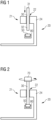
- a vessel 20 having a vessel fastening portion 21 and a vessel through hole 22 in the vessel fastening portion 21.
- the vessel fastening portion 21 comprises a vessel flange 24.
- Fig. 1 furthers shows a stud 30 in the vessel through hole 22, wherein the stud 30 comprises an upper portion 31 protruding from the tower through hole 12 in an upward direction and a lower portion 32 protruding from the vessel through hole 22 in a downward direction.
- a lower fastening element 50 and a mounting shelf 80 are shown.
- the stud 30 is moved downward through the vessel through hole 22 into the lower fastening element 50, which is supported at the mounting shelf 80.
- the stud 30 is provided as a threaded rod and the lower fastening element 50 is provided as a nut.
- the stud 30 is rotated into the lower fastening element 50 by using a mechanical rotation means 70.
- a mechanical rotation means 70 it could alternatively be screwed into the nut manually or the lower fastening element 50 could be screwed onto the stud 30 by holding the stud 30 still and rotating the lower fastening element 50, either manually or by means of the mounting shelf 80.
- Fig. 3 shows the stud 30 being moved in a downward direction and in fig. 4 , a wind turbine tower 10 is landed onto the vessel 20.
- the tower fastening portion 11 is landed onto the vessel fastening portion 21.
- the tower fastening portion 11 comprises a tower through hole 12 and a tower flange 14, in which the tower through hole 12 is located.
- the stud 30 is positioned in the vessel through hole 22 such that the lower portion 32 protrudes from the vessel through hole 22 in the downward direction and the lower fastening element 50 is attached at the lower portion 32 before the tower 10 is landed onto the vessel 20.
- the stud 30 is moved in the downward direction until the upper portion 31 is located in the vessel through hole 22 before landing the tower 10 onto the vessel 20.
- the stud 30 is moved in the upward direction until the upper portion 31 is moved through the tower through hole 12 and outside the tower through hole 12 after the tower 10 is landed in the desired position onto the vessel 20. That is, after the stud 30 is located in the tower through hole 12 and the vessel through hole 22, the upper portion 31 protrudes from the tower through hole 12 in the upward direction and the lower portion 32 protrudes from the vessel through hole 22 in the downward direction.
- an upper fastening element 60 is attached to the upper portion 31 of the stud 30.
- the upper fastening 60 is provided as a nut, which is screwed onto the stud 30.
- a tensioning tool 90 is used to fasten the tower fastening portion 11 to the vessel fastening portion 21 by screwing the upper fastening element 60 further onto the stud 30.
- Fig. 8 shows a further stud 30 being located in a further tower through hole 12 and a further vessel through hole 22 for fastening the tower 10 in a more secure way to the vessel 20 by means of further fastening elements 50, 60.
- the fastening in fig. 7 can be considered as a so called survival mode and the additional fastening shown in fig.
- Fig. 10 shows a sea transit of the tower 10 on the vessel 20, during which the mounting shelf is moved and/or shifted into a lower position.
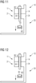
- Fig. 11 shows the state, in which the vessel 20 arrived at a foundation 40 (shown in fig. 14 ) and the lower fastening element 50 is removed from the lower portion 32 of the first stud 30 by means of the mounting shelf in transit mode.
- Fig. 12 shows the step of removing the further lower fastening element 50 from the further stud 30 in survival mode.
- the tower 10 will be lifted as soon as every lower fastening element 50 has been removed from every stud 30, wherein the tower 10 is lifted from the vessel 20 with the studs 30 being at the tower fastening portion 11.
- the upper fastening elements 60 will remain at the studs 30 and the upper portions 31, respectively, when lifting the tower 10 from the vessel 20.
- the foundation 40 of the described example comprises a foundation fastening portion 41 and a foundation through hole 42 in the foundation fastening portion 41.
- the foundation through hole 42 is located in a foundation flange 44 of the foundation fastening portion 41.
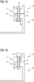
- the tower 10 is landed onto the foundation 40 with the tower through hole 12 at the foundation through hole 42, while guiding the lower portion 32 of the stud 30, still being at the tower fastening portion 11, through the foundation through hole 42.
- the lower fastening element 50 is attached at the lower portion 32.
- the nut shaped lower fastening element 50 is screwed onto the lower portion 32 of the stud 30 by means of the mounting shelf 80.
- the tower fastening portion 11 is fastened to the foundation fastening portion 41 by means of the lower fastening element 50 and the upper fastening element 60.
- the upper fastening element 60 is tensioned by the tensioning tool 90.
- Fig. 17 and fig. 18 show parts of a tower 10 and a vessel 20 according to prior art, in order to describe major differences between the conventional and the inventive way of installing the tower 10 on the vessel 20.
- the screw 30a used for fastening the tower 10 onto the vessel 20 has a firm screw head 50a.
- the screw 30a has to be replaced by a further screw 30a. This way of processing is described in more detail in the introductory part of the description above.
Landscapes
- Engineering & Computer Science (AREA)
- Life Sciences & Earth Sciences (AREA)
- Sustainable Development (AREA)
- Sustainable Energy (AREA)
- Chemical & Material Sciences (AREA)
- Combustion & Propulsion (AREA)
- Mechanical Engineering (AREA)
- General Engineering & Computer Science (AREA)
- Wind Motors (AREA)
- Foundations (AREA)
Abstract
The invention relates to a method for installing a wind turbine tower (10), wherein the tower (10) comprises a tower fastening portion (11) and a tower through hole (12) in the tower fastening portion (11), comprising: providing a vessel (20) with a vessel fastening portion (21) and a vessel through hole (22) in the vessel fastening portion (21), landing the tower (10) onto the vessel (20) with the tower through hole (12) at the vessel through hole (22), positioning a stud (30) in the tower through hole (12) and the vessel through hole (22), wherein the stud (30) comprises an upper portion (31) protruding from the tower through hole (12) in an upward direction and a lower portion (32) protruding from the vessel through hole (22) in a downward direction, fastening the tower fastening portion (11) to the vessel fastening portion (21) by means of a lower fastening element (50) attached to the lower portion (32) and an upper fastening element (60) attached to the upper portion (31), wherein the lower fastening element (50) and the upper fastening element (60) are both detachable from the stud (30) in a non-destructive way.
Description
- The present invention relates to a method for installing a wind turbine tower and in particular for seafastening the wind turbine tower for transporting the tower on a vessel to a foundation.
- In prior art, it is known to install the tower on a vessel for transporting it to a foundation with screws and nuts. When seafastening the tower on the vessel, there is limited space for handling the screws and bolts because of tower internals and other equipment inside the tower. Further, it is difficult to handle the screws manually because of the size and/or weight of the studs.
- Until now, screws like cylinder head screws are used for fastening wind turbine towers via a tower fastening portion to a vessel fastening portion. When installing the tower at the vessel fastening portion, the screws are guided through vessel through holes in the vessel fastening portion with the screw heads on a lower portion of the screws. That is, the screws are pushed from bottom to top in an upward direction through the vessel through holes and the coaxially positioned tower through holes, until the upper part of the screws protrude from the tower through holes in an upward direction and the screw heads contact the outer surfaces of a lower part of the vessel fastening portions around the vessel through holes. Thereafter, a nut is screwed onto each upper portion of the screws protruding from the tower through holes. After the vessel with the tower on it has reached the foundation for the tower, the screws are replaced by new screws, which are inserted into the tower through holes in a downward direction, that is, from top to bottom, after the older screws have been removed.
- Since the vessel is moving, for example on water, installation times on the vessel have to be as short as possible in order to prevent unintentional damages to the tower. This is challenging in particular when it comes to replacing the old screws by the new screws for lifting the tower from the vessel to the foundation.
- It is an object of the present invention to address the above mentioned issues. In particular, it is an object of the present invention to provide an improved method for seafastening a wind turbine tower.
- Aforesaid object is achieved by the subject-matters of the claims. In particular, the object is achieved by a method according to claim 1. Further features and details of the invention can be drawn from the dependent claims, the description and the figures.
- According to the present invention, a method is provided for installing a wind turbine tower, wherein the tower comprises a tower fastening portion and a tower through hole in the tower fastening portion, comprising the steps of:
- providing a vessel with a vessel fastening portion and a vessel through hole in the vessel fastening portion,
- landing the tower onto the vessel with the tower through hole at the vessel through hole,
- positioning a stud in the tower through hole and the vessel through hole, wherein the stud comprises an upper portion protruding from the tower through hole in an upward direction and a lower portion protruding from the vessel through hole in a downward direction,
- fastening the tower fastening portion to the vessel fastening portion by means of a lower fastening element attached to the lower portion and an upper fastening element attached to the upper portion, wherein the lower fastening element and the upper fastening element are both detachable from the stud in a non-destructive way.
- Within the scope of the present invention, it has been found that replacing the traditional screw by the stud without the screw head provides the possibility of an improved way of installing the tower onto the vessel. In particular, the tower can be installed in a way that provides an improved starting position for moving the tower from the vessel to the foundation later on.
- Having the stud with the lower fastening element being detachable from the stud, that is, having no fixed screw head, it is possible to just remove and/or detach the lower fastening element from the stud for lifting the tower from the vessel. Further, the old and/or initial stud will then be reused for fastening the tower onto the foundation. Hence, the stud can be reused during the installation process of the tower. Even the lower fastening means may be reused, depending on the given circumstances and/or safety requirements. In addition, the inventive method not only simplifies the method known in prior art, but also provides the basis for a faster way of moving and installing the tower from the vessel onto the foundation.
- The above described method it not restricted to the order of the above indents. That is, an alternative order of the described method steps is possible. For example, positioning the stud in the vessel through hole may be performed before and/or during landing the tower onto the vessel. Attaching the lower fastening element may be performed before or after positioning the stud in the vessel through hole and/or the tower through hole.
- The tower through hole can be understood as at least one tower through hole. The vessel through hole can be understood as at least one vessel through hole. The stud can be understood as at least one stud. That is, it is possible that the tower is fastened to the vessel by means of a plurality of studs in a corresponding plurality of tower through holes and vessel through holes. The described steps may then be performed after one another or in a combined manner. For example, in one alternative, every stud may be inserted into the holes and when every stud is in position, the fastening elements are attached and fastened. According to another alternative, the tower may be fastened onto the vessel by means of one stud in the described manner and by means of at least one further stud in the same manner.
- The upper portion may be understood as an upper end portion of the stud. The lower portion may be understood as a lower end portion of the stud. The stud may comprise an external thread in the lower portion, the upper portion and/or over the entire length of the stud. The stud may be provided as a rod- and/or pin-shaped stud.
- The tower fastening portion may be understood as a fastening portion, for example a flange portion, in a lower and/or bottom part of the tower. Hence, the tower through hole may be located in a tower flange of the tower fastening portion. In this way, conflicts with tower internals can be prevented when handling the stud or studs. The vessel through hole may be located in a vessel flange of the vessel fastening portion.
- The vessel can be understood as a floating and/or ship-like platform for transporting the tower to a foundation at sea. However, the vessel may also be understood as a land-based transportation platform. Landing the tower onto the vessel may be understood as moving and/or lifting the tower onto the vessel. Fastening the tower fastening portion to the vessel fastening portion may be understood as fixing and/or mounting the tower fastening portion to the vessel fastening portion. Fastening the tower fastening portion to the vessel fastening portion by means of the lower fastening element and the upper fastening element may be understood such that the lower fastening element and the upper fastening element may be used, in addition to further fastening tools like the stud and the fastening portions, for fastening the tower to the vessel.
- According to a further embodiment of the invention, the stud may be positioned in the vessel through hole such that the lower portion protrudes from the vessel through hole in the downward direction and the lower fastening element may be attached at the lower portion before the tower is landed onto the vessel. In this way, the stud with the attached lower fastening element may be pushed into the tower through hole as soon as the tower fastening portion is in a suitable position at the vessel fastening portion while having a mechanical stop by means of the lower fastening element.
- In a further embodiment of the invention it is possible that the stud is moved in the downward direction until the upper portion is located in the vessel through hole before and/or when landing the tower onto the vessel and the stud is moved in the upward direction until the upper portion is moved through the tower through hole and outside the tower through hole after the tower landed onto the vessel. In this way, the stud can be easily held in the desired position until the tower contacts the vessel and can then be quickly pushed into the tower through hole.
- Moreover, the inventive method may be performed such that the lower fastening element is attached to the lower portion by screwing the lower fastening element onto the lower portion and the upper fastening element is attached to the upper portion by screwing the upper fastening element onto the upper portion. That is, the upper fastening element and the lower fastening element may each comprise an internal thread, by means of which they may be screwed onto the stud and the external thread, respectively. The lower fastening element and the upper fastening element may both be provided as nuts. In this way, the lower fastening element and the upper fastening element may be easily attached to the stud and detached from the stud. The lower fastening element and the upper fastening element being detachable from the stud in a non-destructive way may thus be understood such that they may be loosened and/or screwed off from the stud.
- Furthermore, the stud may be rotated into the lower fastening element by using a mechanical rotation means. By automating the rotation of the stud into the lower fastening means, this process can be performed quicker, more consistent and with higher safety compared to conventional methods. Moreover, it is possible to use heavier studs like studs with a weight over 10 kg or over 15 kg. The mechanical rotation means may be provided as a robot for rotating and/or spinning the stud.
- In addition, or alternatively, the lower fastening element may be attached at and/or to the lower portion by using a mounting shelf for holding the lower fastening element and/or for lifting the lower fastening element. In particular, the mounting shelf can be used for lifting the lower fastening element with the stud on the lower fastening element. For example, the lower fastening element may be supported at the mounting shelf, which might be part of a robot and/or machine. Then, the stud may be placed into the vessel through hole and onto the lower fastening element. That is, the stud is then supported by the lower fastening element and the mounting shelf. Thereafter, the stud may be attached to the lower mounting element, for example, may be manually screwed into the lower mounting element, which might be provided as a nut. Using the mounting shelf provides an improved way of attaching the lower fastening element to the stud. In particular, by supporting the stud on the lower fastening element and the mounting shelf, respectively, an easier handling of the stud can be achieved for the process of attaching the lower fastening element to the stud. The mounting shelf might comprise a mechanical, hydraulic and/or pneumatic lifting device for lifting and/or lowering the lower fastening element.
- The inventive method may further comprise the following steps for installing the tower on a foundation, in particular on an offshore foundation:
- detaching the lower fastening element from the stud,
- lifting the tower from the vessel with the stud being at the tower fastening portion having the upper fastening element at the upper portion,
- providing a foundation with a foundation fastening portion and a foundation through hole in the foundation fastening portion,
- landing the tower onto the foundation with the tower through hole at the foundation through hole, while guiding the lower portion of the stud, still being at the tower fastening portion, through the foundation through hole,
- attaching the lower fastening element at the lower portion, fastening the tower fastening portion to the foundation fastening portion by means of the lower fastening element and the upper fastening element.
- Having installed the lower fastening element instead of having a conventional screw head, the lower fastening element can be easily detached from the stud in order to lift the tower including the stud or studs and the upper fastening element or elements from the vessel. In this way, the critical time for fastening the tower onto the foundation can be held relatively short. The foundation through hole may be located in a foundation flange of the foundation fastening portion. The foundation may be understood as an offshore foundation but also as a platform, where the tower has to be installed eventually.
- According to a further embodiment of the present invention, the tower comprises a plurality of tower through holes, the vessel comprises a plurality of vessel through holes and/or the foundation comprises a plurality of foundation through holes, wherein a plurality of studs is positioned in the tower through holes and the vessel through holes, wherein each stud comprises an upper portion protruding from each tower through hole in an upward direction and a lower portion protruding from each vessel through hole in a downward direction. Further, each stud may be moved in the downward direction until each upper portion is located in each corresponding vessel through hole before and/or when landing the tower onto the vessel and each stud may be moved in the upward direction until each upper portion is moved through each corresponding tower through hole and outside each corresponding tower through hole after the tower landed onto the vessel. That is, no stud may protrude from the holes during landing of the tower. Moreover, the tower may be lifted from the vessel with each stud being at the tower fastening portion having attached the corresponding upper fastening element at each upper portion. In this way, the tower may be installed in an even more secure and still easy and space-saving manner.
- Further measures improving the inventive concept can be drawn from the following description of a preferred method, which is schematically shown in the drawings. The features and advantages, which can be drawn from the claims, from the description and from the drawings, might be considered essential alone or in combination with each other.
- In the drawings:
-
Figs. 1 - 16 show a tower, a vessel and a foundation for explaining a preferred way of installing a wind turbine tower according to the present invention, and -
Figs. 17 and 18 show a tower, a vessel and a foundation for explaining a way of installing a wind turbine tower according to prior art. - Elements and features having the same function and operating principle are labeled with the same reference signs in the drawings.
- In
fig. 1 , part of avessel 20 is shown having avessel fastening portion 21 and a vessel throughhole 22 in thevessel fastening portion 21. Thevessel fastening portion 21 comprises avessel flange 24.Fig. 1 furthers shows astud 30 in the vessel throughhole 22, wherein thestud 30 comprises anupper portion 31 protruding from the tower throughhole 12 in an upward direction and alower portion 32 protruding from the vessel throughhole 22 in a downward direction. Moreover, alower fastening element 50 and a mountingshelf 80 are shown. In a first step of the installation, thestud 30 is moved downward through the vessel throughhole 22 into thelower fastening element 50, which is supported at the mountingshelf 80. Thestud 30 is provided as a threaded rod and thelower fastening element 50 is provided as a nut. - As shown in
fig. 2 thestud 30 is rotated into thelower fastening element 50 by using a mechanical rotation means 70. Depending on the weight of thestud 30, it could alternatively be screwed into the nut manually or thelower fastening element 50 could be screwed onto thestud 30 by holding thestud 30 still and rotating thelower fastening element 50, either manually or by means of the mountingshelf 80. -
Fig. 3 shows thestud 30 being moved in a downward direction and infig. 4 , awind turbine tower 10 is landed onto thevessel 20. In particular, thetower fastening portion 11 is landed onto thevessel fastening portion 21. Thetower fastening portion 11 comprises a tower throughhole 12 and atower flange 14, in which the tower throughhole 12 is located. In the shown example, thestud 30 is positioned in the vessel throughhole 22 such that thelower portion 32 protrudes from the vessel throughhole 22 in the downward direction and thelower fastening element 50 is attached at thelower portion 32 before thetower 10 is landed onto thevessel 20. As can be seen infig. 3 and fig. 4 , thestud 30 is moved in the downward direction until theupper portion 31 is located in the vessel throughhole 22 before landing thetower 10 onto thevessel 20. - As shown in
fig. 5 , thestud 30 is moved in the upward direction until theupper portion 31 is moved through the tower throughhole 12 and outside the tower throughhole 12 after thetower 10 is landed in the desired position onto thevessel 20. That is, after thestud 30 is located in the tower throughhole 12 and the vessel throughhole 22, theupper portion 31 protrudes from the tower throughhole 12 in the upward direction and thelower portion 32 protrudes from the vessel throughhole 22 in the downward direction. - Thereafter, as shown in
fig. 6 , anupper fastening element 60 is attached to theupper portion 31 of thestud 30. Theupper fastening 60 is provided as a nut, which is screwed onto thestud 30. Afterwards, atensioning tool 90 is used to fasten thetower fastening portion 11 to thevessel fastening portion 21 by screwing theupper fastening element 60 further onto thestud 30.Fig. 8 shows afurther stud 30 being located in a further tower throughhole 12 and a further vessel throughhole 22 for fastening thetower 10 in a more secure way to thevessel 20 by means offurther fastening elements fig. 7 can be considered as a so called survival mode and the additional fastening shown infig. 8 can be considered as a so called transit mode. As a further measure of safety, as shown infig. 9 , thetensioning tool 90 is used to further fastening thelower fastening element 50 as well.Fig. 10 shows a sea transit of thetower 10 on thevessel 20, during which the mounting shelf is moved and/or shifted into a lower position. -
Fig. 11 shows the state, in which thevessel 20 arrived at a foundation 40 (shown infig. 14 ) and thelower fastening element 50 is removed from thelower portion 32 of thefirst stud 30 by means of the mounting shelf in transit mode. -
Fig. 12 shows the step of removing the furtherlower fastening element 50 from thefurther stud 30 in survival mode. - As can be seen in
fig. 13 , thetower 10 will be lifted as soon as everylower fastening element 50 has been removed from everystud 30, wherein thetower 10 is lifted from thevessel 20 with thestuds 30 being at thetower fastening portion 11. As shown infig. 13 , theupper fastening elements 60 will remain at thestuds 30 and theupper portions 31, respectively, when lifting thetower 10 from thevessel 20. - After the
tower 10 was lifted from thevessel 20, it will be landed onto thefoundation 40. Thefoundation 40 of the described example comprises afoundation fastening portion 41 and a foundation throughhole 42 in thefoundation fastening portion 41. In particular, the foundation throughhole 42 is located in afoundation flange 44 of thefoundation fastening portion 41. As shown infig. 14 , thetower 10 is landed onto thefoundation 40 with the tower throughhole 12 at the foundation throughhole 42, while guiding thelower portion 32 of thestud 30, still being at thetower fastening portion 11, through the foundation throughhole 42. - After the
tower 10 landed onto thefoundation 40, as shown infig. 15 , thelower fastening element 50 is attached at thelower portion 32. In particular, the nut shapedlower fastening element 50 is screwed onto thelower portion 32 of thestud 30 by means of the mountingshelf 80. Finally, thetower fastening portion 11 is fastened to thefoundation fastening portion 41 by means of thelower fastening element 50 and theupper fastening element 60. As shown infig. 16 , in order to secure thetower 10 onto thefoundation 40, theupper fastening element 60 is tensioned by thetensioning tool 90. - The aforesaid description of the accompanying drawings is only by the way of detail and example. Specific features of each aspect of the present invention and the figures can be combined which each other if of technical sense.
-
Fig. 17 and fig. 18 show parts of atower 10 and avessel 20 according to prior art, in order to describe major differences between the conventional and the inventive way of installing thetower 10 on thevessel 20. As can be seen infig. 17 , thescrew 30a used for fastening thetower 10 onto thevessel 20 has afirm screw head 50a. When moving thetower 10 from thevessel 20 onto thefoundation 40 afterwards, as shown infig. 18 , thescrew 30a has to be replaced by afurther screw 30a. This way of processing is described in more detail in the introductory part of the description above.
Claims (10)
- A method for installing a wind turbine tower (10), wherein the tower (10) comprises a tower fastening portion (11) and a tower through hole (12) in the tower fastening portion (11), comprising:- providing a vessel (20) with a vessel fastening portion (21) and a vessel through hole (22) in the vessel fastening portion (21),- landing the tower (10) onto the vessel (20) with the tower through hole (12) at the vessel through hole (31),- positioning a stud (30) in the tower through hole (12) and the vessel through hole (22), wherein the stud (30) comprises an upper portion (31) protruding from the tower through hole (12) in an upward direction and a lower portion (32) protruding from the vessel through hole (22) in a downward direction,- fastening the tower fastening portion (11) to the vessel fastening portion (21) by means of a lower fastening element (50) attached to the lower portion (32) and an upper fastening element (60) attached to the upper portion (31), wherein the lower fastening element (50) and the upper fastening element (60) are both detachable from the stud (30) in a non-destructive way.
- The method according to claim 1, wherein the stud (30) is positioned in the vessel through hole (22) such that the lower portion (32) protrudes from the vessel through hole (22) in the downward direction and the lower fastening element (50) is attached at the lower portion (32) before the tower (10) is landed onto the vessel (20).
- The method according to claim 2, wherein the stud (30) is moved in the downward direction until the upper portion (31) is located in the vessel through hole (22) before and/or when landing the tower (10) onto the vessel (20) and the stud (30) is moved in the upward direction until the upper portion (31) is moved through the tower through hole (12) and outside the tower through hole (12) after the tower (10) landed onto the vessel (20).
- The method according to any one of the preceding claims, wherein the lower fastening element (50) is attached to the lower portion (32) by screwing the lower fastening element (50) onto the lower portion (32) and the upper fastening element (60) is attached to the upper portion (31) by screwing the upper fastening element (60) onto the upper portion (31).
- The method according to one of the preceding claims, wherein the stud (30) is rotated into the lower fastening element (50) by using a mechanical rotation means (70).
- The method according to one of the preceding claims, wherein the lower fastening element (50) is attached at the lower portion (32) by using a mounting shelf (80) for holding the lower fastening element (50) and/or for lifting the lower fastening element (50).
- A method according to one of the preceding claims, further comprising:- detaching the lower fastening element (50) from the stud (30),- lifting the tower (10) from the vessel (20) with the stud (30) being at the tower fastening portion (11) having the upper fastening element (60) at the upper portion (31),- providing a foundation (40) with a foundation fastening portion (41) and a foundation through hole (42) in the foundation fastening portion (41),- landing the tower (10) onto the foundation (40) with the tower through hole (12) at the foundation through hole (42), while guiding the lower portion (32) of the stud (30), still being at the tower fastening portion (11), through the foundation through hole (42),- attaching the lower fastening element (50) at the lower portion (32),- fastening the tower fastening portion (11) to the foundation fastening portion (41) by means of the lower fastening element (50) and the upper fastening element (60).
- The method according to one of the preceding claims, wherein the tower (10) comprises a plurality of tower through holes (12) and/or the vessel (20) comprises a plurality of vessel through holes (22), wherein a plurality of studs (30) is positioned in the tower through holes (12) and the vessel through holes (22), wherein each stud (30) comprises an upper portion (31) protruding from each tower through hole (12) in an upward direction and a lower portion (32) protruding from each vessel through hole (22) in a downward direction.
- The method according to one of the preceding claims, wherein the tower (10) comprises a plurality of tower through holes (12) and/or the vessel (20) comprises a plurality of vessel through holes (22), wherein a plurality of studs (30) is positioned in the tower through holes (12) and the vessel through holes (22), wherein each stud (30) is moved in the downward direction until each upper portion (31) is located in each corresponding vessel through hole (22) before and/or when landing the tower (10) onto the vessel (20) and each stud (30) is moved in the upward direction until each upper portion (31) is moved through each corresponding tower through hole (12) and outside each corresponding tower through hole (12) after the tower (10) landed onto the vessel (20).
- The method according to one of the preceding claims, wherein the tower (10) comprises a plurality of tower through holes (12) and/or the vessel (20) comprises a plurality of vessel through holes (22), wherein a plurality of studs (30) is positioned in the tower through holes (12) and the vessel through holes (22), wherein the tower is lifted from the vessel (20) with each stud (30) being at the tower fastening portion (11) having attached the corresponding upper fastening element (60) at each upper portion (31).
Priority Applications (5)
| Application Number | Priority Date | Filing Date | Title |
|---|---|---|---|
| EP23166681.9A EP4442993A1 (en) | 2023-04-05 | 2023-04-05 | Method for installing a wind turbine tower |
| CN202480021636.6A CN120882971A (en) | 2023-04-05 | 2024-03-06 | Method for installing wind turbine towers |
| US19/166,738 US20260110288A1 (en) | 2023-04-05 | 2024-03-06 | Method for installing a wind turbine tower |
| PCT/EP2024/055856 WO2024208522A1 (en) | 2023-04-05 | 2024-03-06 | Method for installing a wind turbine tower |
| EP24708819.8A EP4662406A1 (en) | 2023-04-05 | 2024-03-06 | Method for installing a wind turbine tower |
Applications Claiming Priority (1)
| Application Number | Priority Date | Filing Date | Title |
|---|---|---|---|
| EP23166681.9A EP4442993A1 (en) | 2023-04-05 | 2023-04-05 | Method for installing a wind turbine tower |
Publications (1)
| Publication Number | Publication Date |
|---|---|
| EP4442993A1 true EP4442993A1 (en) | 2024-10-09 |
Family
ID=85979861
Family Applications (2)
| Application Number | Title | Priority Date | Filing Date |
|---|---|---|---|
| EP23166681.9A Withdrawn EP4442993A1 (en) | 2023-04-05 | 2023-04-05 | Method for installing a wind turbine tower |
| EP24708819.8A Pending EP4662406A1 (en) | 2023-04-05 | 2024-03-06 | Method for installing a wind turbine tower |
Family Applications After (1)
| Application Number | Title | Priority Date | Filing Date |
|---|---|---|---|
| EP24708819.8A Pending EP4662406A1 (en) | 2023-04-05 | 2024-03-06 | Method for installing a wind turbine tower |
Country Status (4)
| Country | Link |
|---|---|
| US (1) | US20260110288A1 (en) |
| EP (2) | EP4442993A1 (en) |
| CN (1) | CN120882971A (en) |
| WO (1) | WO2024208522A1 (en) |
Citations (3)
| Publication number | Priority date | Publication date | Assignee | Title |
|---|---|---|---|---|
| EP3088735A1 (en) * | 2015-04-28 | 2016-11-02 | Siemens Aktiengesellschaft | Method and arrangement to transport a tower of a wind turbine on a vessel |
| US20220228565A1 (en) * | 2019-05-21 | 2022-07-21 | Vestas Wind Systems A/S | A method for erecting a wind turbine tower using stud bolts |
| EP4043721A1 (en) * | 2021-02-15 | 2022-08-17 | Siemens Gamesa Renewable Energy A/S | Installation system and method of upending and installing a wind turbine tower |
Family Cites Families (1)
| Publication number | Priority date | Publication date | Assignee | Title |
|---|---|---|---|---|
| WO2020233763A1 (en) * | 2019-05-21 | 2020-11-26 | Vestas Wind Systems A/S | A tool assembly for tensioning tower bolts of a wind turbine tower |
-
2023
- 2023-04-05 EP EP23166681.9A patent/EP4442993A1/en not_active Withdrawn
-
2024
- 2024-03-06 US US19/166,738 patent/US20260110288A1/en active Pending
- 2024-03-06 CN CN202480021636.6A patent/CN120882971A/en active Pending
- 2024-03-06 WO PCT/EP2024/055856 patent/WO2024208522A1/en not_active Ceased
- 2024-03-06 EP EP24708819.8A patent/EP4662406A1/en active Pending
Patent Citations (3)
| Publication number | Priority date | Publication date | Assignee | Title |
|---|---|---|---|---|
| EP3088735A1 (en) * | 2015-04-28 | 2016-11-02 | Siemens Aktiengesellschaft | Method and arrangement to transport a tower of a wind turbine on a vessel |
| US20220228565A1 (en) * | 2019-05-21 | 2022-07-21 | Vestas Wind Systems A/S | A method for erecting a wind turbine tower using stud bolts |
| EP4043721A1 (en) * | 2021-02-15 | 2022-08-17 | Siemens Gamesa Renewable Energy A/S | Installation system and method of upending and installing a wind turbine tower |
Also Published As
| Publication number | Publication date |
|---|---|
| US20260110288A1 (en) | 2026-04-23 |
| EP4662406A1 (en) | 2025-12-17 |
| WO2024208522A1 (en) | 2024-10-10 |
| CN120882971A (en) | 2025-10-31 |
Similar Documents
| Publication | Publication Date | Title |
|---|---|---|
| CN101618506B (en) | Installation tool and installation method for rudderstock hydraulic nut of supertanker | |
| AU2012396364B2 (en) | Method for disassembling and/or assembling an underwater section of a retractable thruster unit | |
| KR101285370B1 (en) | Bearing puller for air end of main air compressor in subway train | |
| EP3574149A1 (en) | A method and tool for installation of an offshore wind turbine | |
| US20150361634A1 (en) | Assembly for mooring a pile with a mooring line and method implemented with said assembly | |
| US5092711A (en) | Diverless installation of riser clamps onto fixed or compliant offshore platforms | |
| US20260110288A1 (en) | Method for installing a wind turbine tower | |
| WO1986005551A1 (en) | Apparatus and method of packaging an engine cylinder assembly | |
| KR20150004552U (en) | Hole-cover apparatus for ship | |
| CN201432279Y (en) | Tool for installing rudderstock hydraulic nut on supertank | |
| EP2708733B1 (en) | Guiding system for guiding a root of a rotor blade during installation and method of mounting a rotor blade on a rotor hub of a wind generator | |
| CN101564811B (en) | Blade nut tightening device and use method thereof | |
| CN109931228B (en) | Method for anchoring a retaining device in a wind turbine and adapter | |
| CN106625389A (en) | Special tool and method for demounting and mounting of high-pressure self-sealing manhole | |
| KR200497122Y1 (en) | Turbine valve lever pin removal device | |
| JP5510863B2 (en) | Floating roof dismantling construction method for floating roof storage tank | |
| KR20090116946A (en) | Reactor stud driver with separation and coalescence unit | |
| WO2024072818A2 (en) | Automated trolley system for tightening tower segments in wind turbines | |
| CN114374302A (en) | Large-scale shielding motor rotor assembly and motor turning-over process | |
| JP2000071133A (en) | Bolt dismounting-mounting device and its method | |
| KR20120007135U (en) | Winch seat apparatus for ship | |
| JP3717911B2 (en) | Steel tower dismantling method and work jig by helicopter | |
| JP4755479B2 (en) | Tower dismantling method by helicopter | |
| JPS618282A (en) | Bolt screwing and unscrewing device | |
| CN120039758A (en) | Hoisting method and hoisting structure for segmented deck |
Legal Events
| Date | Code | Title | Description |
|---|---|---|---|
| PUAI | Public reference made under article 153(3) epc to a published international application that has entered the european phase |
Free format text: ORIGINAL CODE: 0009012 |
|
| STAA | Information on the status of an ep patent application or granted ep patent |
Free format text: STATUS: THE APPLICATION HAS BEEN PUBLISHED |
|
| AK | Designated contracting states |
Kind code of ref document: A1 Designated state(s): AL AT BE BG CH CY CZ DE DK EE ES FI FR GB GR HR HU IE IS IT LI LT LU LV MC ME MK MT NL NO PL PT RO RS SE SI SK SM TR |
|
| STAA | Information on the status of an ep patent application or granted ep patent |
Free format text: STATUS: THE APPLICATION IS DEEMED TO BE WITHDRAWN |
|
| 18D | Application deemed to be withdrawn |
Effective date: 20250410 |