EP4442919B1 - Bauelement, anordnung und wand für den architektonischen aufbau, insbesondere rahmenhäuser - Google Patents
Bauelement, anordnung und wand für den architektonischen aufbau, insbesondere rahmenhäuser Download PDFInfo
- Publication number
- EP4442919B1 EP4442919B1 EP23461552.4A EP23461552A EP4442919B1 EP 4442919 B1 EP4442919 B1 EP 4442919B1 EP 23461552 A EP23461552 A EP 23461552A EP 4442919 B1 EP4442919 B1 EP 4442919B1
- Authority
- EP
- European Patent Office
- Prior art keywords
- head
- structural
- elements
- structural element
- shaft
- Prior art date
- Legal status (The legal status is an assumption and is not a legal conclusion. Google has not performed a legal analysis and makes no representation as to the accuracy of the status listed.)
- Active
Links
Images




Classifications
-
- E—FIXED CONSTRUCTIONS
- E04—BUILDING
- E04B—GENERAL BUILDING CONSTRUCTIONS; WALLS, e.g. PARTITIONS; ROOFS; FLOORS; CEILINGS; INSULATION OR OTHER PROTECTION OF BUILDINGS
- E04B2/00—Walls, e.g. partitions, for buildings; Wall construction with regard to insulation; Connections specially adapted to walls
- E04B2/02—Walls, e.g. partitions, for buildings; Wall construction with regard to insulation; Connections specially adapted to walls built-up from layers of building elements
- E04B2/14—Walls having cavities in, but not between, the elements, i.e. each cavity being enclosed by at least four sides forming part of one single element
- E04B2/22—Walls having cavities in, but not between, the elements, i.e. each cavity being enclosed by at least four sides forming part of one single element using elements having a general shape differing from that of a parallelepiped
-
- E—FIXED CONSTRUCTIONS
- E04—BUILDING
- E04B—GENERAL BUILDING CONSTRUCTIONS; WALLS, e.g. PARTITIONS; ROOFS; FLOORS; CEILINGS; INSULATION OR OTHER PROTECTION OF BUILDINGS
- E04B2/00—Walls, e.g. partitions, for buildings; Wall construction with regard to insulation; Connections specially adapted to walls
- E04B2/02—Walls, e.g. partitions, for buildings; Wall construction with regard to insulation; Connections specially adapted to walls built-up from layers of building elements
- E04B2/42—Walls having cavities between, as well as in, the elements; Walls of elements each consisting of two or more parts, kept in distance by means of spacers, at least one of the parts having cavities
- E04B2/50—Walls having cavities between, as well as in, the elements; Walls of elements each consisting of two or more parts, kept in distance by means of spacers, at least one of the parts having cavities using elements having a general shape differing from that of a parallelepiped
-
- E—FIXED CONSTRUCTIONS
- E04—BUILDING
- E04C—STRUCTURAL ELEMENTS; BUILDING MATERIALS
- E04C2/00—Building elements of relatively thin form for the construction of parts of buildings, e.g. sheet materials, slabs, or panels
- E04C2/02—Building elements of relatively thin form for the construction of parts of buildings, e.g. sheet materials, slabs, or panels characterised by specified materials
- E04C2/04—Building elements of relatively thin form for the construction of parts of buildings, e.g. sheet materials, slabs, or panels characterised by specified materials of concrete or other stone-like material; of asbestos cement; of cement and other mineral fibres
- E04C2/044—Building elements of relatively thin form for the construction of parts of buildings, e.g. sheet materials, slabs, or panels characterised by specified materials of concrete or other stone-like material; of asbestos cement; of cement and other mineral fibres of concrete
-
- E—FIXED CONSTRUCTIONS
- E04—BUILDING
- E04C—STRUCTURAL ELEMENTS; BUILDING MATERIALS
- E04C3/00—Structural elongated elements designed for load-supporting
- E04C3/30—Columns; Pillars; Struts
- E04C3/34—Columns; Pillars; Struts of concrete other stone-like material, with or without permanent form elements, with or without internal or external reinforcement, e.g. metal coverings
-
- E—FIXED CONSTRUCTIONS
- E04—BUILDING
- E04B—GENERAL BUILDING CONSTRUCTIONS; WALLS, e.g. PARTITIONS; ROOFS; FLOORS; CEILINGS; INSULATION OR OTHER PROTECTION OF BUILDINGS
- E04B2/00—Walls, e.g. partitions, for buildings; Wall construction with regard to insulation; Connections specially adapted to walls
- E04B2/02—Walls, e.g. partitions, for buildings; Wall construction with regard to insulation; Connections specially adapted to walls built-up from layers of building elements
- E04B2002/0202—Details of connections
- E04B2002/0204—Non-undercut connections, e.g. tongue and groove connections
- E04B2002/021—Non-undercut connections, e.g. tongue and groove connections of triangular shape
-
- E—FIXED CONSTRUCTIONS
- E04—BUILDING
- E04C—STRUCTURAL ELEMENTS; BUILDING MATERIALS
- E04C2/00—Building elements of relatively thin form for the construction of parts of buildings, e.g. sheet materials, slabs, or panels
- E04C2002/001—Mechanical features of panels
- E04C2002/004—Panels with profiled edges, e.g. stepped, serrated
Definitions
- the invention relates to the field of construction, and more specifically to the structural elements used in the technique of building frame houses from prefabricated (ready-made) structural elements, and to the system containing these structural elements and the wall built from these structural elements.
- Frame houses have been known in the state of the art for a long time.
- Frame technology refers to the way walls are constructed.
- a load-bearing skeleton of the building is first being created, which is then filled with other building materials, such as bricks or insulation materials, to create a full (not openwork) wall.
- An advantageous feature of frame houses is the possibility of achieving very good thermal insulation of the walls, which is achieved because the space of the frame can be filled mainly or exclusively with insulating material.
- insulating materials can be placed only on the outside of the wall or on the inside of the wall.
- the skeleton of a building can also be formed as a monolithic concrete frame.
- the building skeleton is cast on site from concrete using formwork and reinforcement.
- Such a method of construction is not quite an actual alternative to wood or metal framing due to the much larger distances between the structural elements of the monolithic concrete frame, which de facto makes it impossible to fill such a frame with only insulating materials.
- a timber frame wall consists mainly of wooden vertical beams and horizontal beams.
- Vertical structural beams are long and narrow - they are at least as long as one floor of the building (that is, about 3-4m) and have a relatively small cross section (50-150mm in single-family buildings).
- the main task of vertical beams is to transfer vertical pressure forces.
- Horizontal beams are long or short (40-60 cm) and the main task of horizontal elements - shorter beams and connectors, is to stiffen the structure by connecting them to vertical beams.
- Specially prepared wood is used to produce the frame elements.
- the stiffness of the timber frame structure is further ensured by attaching sheathing to the frame in the form of boards such as OSB, gypsum board, etc.
- the wall structure prepared in this way is filled with insulating material, usually mineral wool.
- a wall made with this technology has many other layers, such as wind insulation, vapor insulation, grates for the installation of additional external insulation or facade.
- Many variants of timber frame house construction are known. These include Canadian, Scandinavian and German houses. They differ in the method of construction, the layout of the wall layers, but the general structural principle is similar in these construction systems.
- Metal framing technology is very similar to wood framing technology except that the construction material instead of wood is steel protected against corrosion.
- Metal framing eliminates some of the disadvantages of wood framing technology such as flammability.
- the main disadvantage is the risk of corrosion of metal structures, especially at joints, which are difficult to protect well against rust.
- Metallic structures are usually more expensive than wooden ones. This causes metal framing technology to be used much less frequently than wood framing technology.
- the skeleton of the building is formed from cast concrete columns and floors reinforced with steel.
- the advantages of this technology are the high strength of the structure. Disadvantages of this technology include:
- Document FR 961 163 A reveals a Structural element in the form of a column, for architectural construction of frame walls of buildings, containing shaft in the form of vertical support beam, which shaft has a bottom contact surface on the lower side and head connected to the top of the shaft, which head extends substantially horizontally, perpendicular to the Z-axis of the shaft and symmetrical with respect to the shaft, in at least two opposite directions forming at least two side arms, and from above the head includes the top surface of the head.
- the purpose of the invention is to enable low-cost and fast construction of structural walls of buildings that can have high thermal insulation, which is necessary for the construction of energy-efficient and passive buildings.
- the purpose of the invention is achieved by making it possible to quickly erect frame walls from prefabricated elements without the need for a crane, even by a single person.
- the purpose of the invention is to develop a construction method that eliminates the disadvantages of timber frame technology and gives the structural walls additional desirable performance characteristics.
- the invention makes it possible to build cheaper and warmer walls compared to those currently used in timber frame construction technology.
- the purpose of the invention is to provide such structural elements and such wall construction technology that will allow easy and quick erection and construction of frame walls, including structural walls, from ready-made structural and insulation elements without the need for cranes (even by a single person).
- the essence of the invention is to solve the problem of efficiently and quickly joining prefabricated concrete elements, including those of low weight (up to 30 kg) and small size, in order to create a frame structure based on such elements.
- the invention makes it possible to easily and quickly insulate the resulting wall skeleton or give it other desired functional characteristics by using specially designed insulating bricks matched to the wall skeleton.
- the invention makes it easy to give different functional characteristics to different parts of the wall, which will also facilitate the construction of intelligent buildings.
- the invention enables low-cost construction of frame wall structures around the world, including in places where timber-frame technology cannot be used due to the lack of wood.
- Structural element 1 in the form of a column, for architectural construction of frame walls of buildings, containing:
- the tongues 6 have the profile of a right-angled triangle, in which one of the right-angle side surfaces 6b of the tongue 6 is perpendicular to the upper surface of the head 3b .
- the upper contact surface 6a forms an angle of 30° with respect to the horizontal or the upper surface of the head 3b and/or the lower contact surface 5a forms an angle of 30° with the upper surface of the head 3b and the head 3 has a lower plane 3a , which the lower plane 3a forms with the Z axis of the shaft 2 an obtuse angle advantageously an angle of 120°.
- At least two grooves 5 are connected to each other and form one double groove.
- the two tongues 6 either extend beyond the edges of the head 3 or do not extend beyond the edges of the head 3 or do not touch them.
- the shaft 2 is essentially cuboid, cube or cylinder in shape and advantageously has in addition holes 7 adapted for placing elements therein and/or the side surface 2a of the shaft 2 together with the lower surface 3a of the head 3 form an arc.
- the dimensions of the structural element 1 are: maximum width of 40cm, maximum height of 40cm, maximum thickness of 20cm and the maximum weight of the structural element 1 is 30kg and is made of concrete, gypsum, ceramic, polymer or composite.
- it has more than two tongues and more than two grooves and replicates the structural element in any direction.
- the invention also includes an arrangement for the construction of a frame house wall frame comprising at least two structural elements 1 configured to be aligned vertically and horizontally with respect to each other, advantageously the arrangement additionally comprises a structural or insulating part configured to be placed in the hollow space between the structural elements 1 in the form of an insulating brick 8, advantageously in the shape of a substantially hexagon, regular hexagon, circle or ellipse, which insulating brick 8 is advantageously made of insulating materials for example Styrofoam.
- the invention also includes a frame wall of a house, characterized in that it contains at least two structural elements 1 are connected to each other horizontally by means of the right-angle side surfaces 6b of the tongues 6, and vertically by means of the upper surfaces of the head 3b and the lower contact surfaces 5a connected to the upper contact surfaces 6a .
- it contains structural elements 1 advantageously arranged between starting element 12 and ending element 13 and/or system lintels 9, side elements 10 and vertical beams 11.
- the joints of the structural elements 1 are reinforced with bonding and/or reinforcement and/or assembly elements.
- insulating brick 8 which advantageously is configured as a finished exterior façade element of a building.
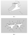
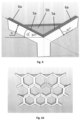
- the invention presented herein relates to, among other things, the structural element 1 shown in Fig. 1 , which is used in the erection of frame structures made of prefabricated elements (advantageously made of concrete) without the use of additional supports, formwork and without the need for cranes. Thanks to a design that uses, among other things, the principles of physics (architecture) involving the transfer of forces by means of architectural (structural) columns and arches, Fig. 10 , smaller structural elements 1 are easily connected to form a larger structure - a wall that is rigid and stable.
- the contact surface (joining force) of structural elements 1 is comparable to that found in masonry buildings, which provides high rigidity to the framework.
- each structural element 1 transfers forces from its own Z-axis to the two Z-axes of two other structural elements 1, at the same time it accepts force from two Z-axes of two other structural elements, through groove 5 on its own Z-axis.
- This mutual transmission of forces is made possible by the large contact surface of the elements, which at the same time ensures that they are firmly and stably connected.
- An example of the execution of the invention is a structural element 1, in the form of a column, which is intended for the construction of frame walls of buildings.
- the structural element 1, in the form of a column includes a shaft 2 and a head 3.
- the elements, from which the object of the invention is constructed, are shown in Fig. 1-5 .
- the shaft 2 is in the form of an elongated vertical beam, which has a bottom contact surface 2b on its lower, free side.
- the shaft 2 is substantially cuboidal in shape, and in other examples of execution it may be substantially cube or cylinder in shape.
- the shaft 2 has a Z-axis, shown in Fig. 1 , which marks the center of symmetry of such shaft 2.
- the shaft 2 can vary in height, but it cannot, including the height of the head 3, exceed the overall width of structural element 1, since such structural element 1 must be stable when the structure is being assembled.
- the overall width in this example is understood to be the largest dimension of the entire structural element 1 in the direction perpendicular to the Z axis.
- the head 3 is permanently connected to the top of the shaft 2 and forms one rigid unit with it, i.e. it forms a column.
- the head 3 extends essentially horizontally (essentially perpendicular with respect to the Z-axis), symmetrically with respect to the shaft 2, in at least two opposite directions to form two side arms, which arms are inscribed in the construction of a tensile-reinforced structural (architectural) arch, Fig. 10 . Visible in Fig. 1 structural elements that are inscribed in the (architectural) arch are the two tongues 6 and the groove 5. The arch is tensile reinforced by the upper part of the head 3b with the top surface of the head 3b also constituting the only, essentially, horizontal element of the head structure.
- the head 3 (advantageously including tongues, grooves and the top surface 3b and the surface 3a) with the top surface of the head 3b, in addition to the function of tensile reinforcement of the arch, performs a stabilizing function, making it easy to stack the structural elements 1 on top of each other.
- the top surface of the head 3b can also serve as a base for the installation of additional reinforcement (reinforcement bars) of the wall horizontally, if necessary.
- the head 3 has at least two tongues 6 on the top surface of the head 3b, which tongues 6 are placed symmetrically on both opposite arms of the head 3, at the end of these arms.
- the tongues 6 are the ends of the structural arch ( Fig. 10 ) that crowns the head 3 and are the vertical-most parts of the head 3.
- the tongues 6 transfer forces in the skeleton from the Z-axis of the structural element 1 to the Z-axis of the next two structural elements 1, which are arranged as another layer of the skeleton.
- Each of the tongues 6 has an upper contact surface 6a.
- the tongues 6 are located at the edges 3c of the head 3 as shown in Figs. 1 and 2 (fitting together with the groove 5 into the cross-section of the structural arch, Fig 10 ).
- the groove 5 In the upper part of the head, there is also a groove 5, which has a lower contact surface 5a on the bottom.
- the groove 5 is located symmetrically (centrally) with respect to the shaft 2, in the upper part of the head 3 on the upper surface of the head 3b and between the tongues 6.
- the shape of the two tongues 6 corresponds to the shape of the same number of grooves 5, such that the tongues 6 fill the grooves 5.
- the grooves 6 may be separated from each other (not shown in the pictures).
- the grooves 5 merge into one double groove consisting of two grooves 5, it is advantageous if the grooves 5 merge into one double groove, because then, when assembled, the tongues 6 of adjacent elements 1 are in contact with the surfaces 6b and transfer loads to each other.
- the groove 5 transfers the forces from the Z-axis of the structural element 1 to the ends of the structural arc, which are the tongues 6, of the subsequent structural element 1.
- the upper contact surface 6a of the tongue 6 corresponds to the lower contact surface 5a of the groove 5 as seen in Fig. 9 .
- the tongues 6 have the shape of a right triangle.
- a connoisseur of the field will know, based on their knowledge, that it is possible to use tongues 6 of another shape such as a rectangle, square or semicircle.
- the rectangular triangle shape is the most optimal. It is important that the tongues 6 including the groove 5 fit into the cross-section of the structural arch ( Fig 10 ).
- one of the right-angle side surfaces 6b, visible in Figs. 1 and 2 is vertical - it is perpendicular to the top surface of the head 3b, it is in line with the direction determined by the Z-axis, which makes it easier to fit the skeleton elements when laying it out as can be seen in Fig. 4 .
- the upper contact surface 6a of the tongues 6 forms an angle of 30° with the upper surface of the head 3b, with respect to the horizontal - perpendicular to the Z axis.
- the angle is shown in Fig. 9 .
- the horizontal is determined by the top surface of the head 3b, perpendicular to the Z axis, which is defined as the plane perpendicular to the direction of gravity on or near the surface of the celestial body.
- Such an angle of inclination ensures the least weight of the structural element 1 and optimal stability of the structural element 1 during stacking of successive structural elements 1.
- Optimal stability and rigidity of the structure is achieved with an angle of inclination of the upper contact surfaces 6a of 30° with respect to the horizontal - perpendicular to the Z axis, because in such an arrangement the contact area of the structural elements 1 in relation to their total area (mass) is the largest. Thus, the structure is the strongest. Other than 30° angle of inclination (both smaller and larger) results in a worse ratio of the contact area of structural elements 1 to their total area (mass). Thus, a greater than 30° angle of inclination lengthens the element 1 vertically causes it to be less stable and heavier, or while keeping the same height of the element increases its weight. In both cases, the ratio of the contact area of structural element 1 to its weight (total mass) deteriorates.
- the contact surface is the surfaces of the structural element 1 (other than vertical) that are in contact with the surfaces of subsequent structural element 1 laid on top of it.
- the front surface is the surface that is visible when looking from the front at the structural element 1 laid out in the skeleton. The front surface does not include the surface of the tongues, since the tongues are not visible when assembled into a skeleton.
- Double structural element 1 (2x structural element 1) has a very high contact area to front area ratio. It is inferior only to traditional flat brick, which has the best ratio of all building materials because it is the flattest.
- the structural element 1 is the only one in the list to have grooves 5 and tongues 6.
- the other building materials analyzed have a flat surface.
- the table shows that the design of the structural element 1 solves well the technical problem of low tangency of structural elements, which occurs in frame structures.
- the lower contact surface 5a of the groove 5 forms an angle of 30° with the upper surface of the head 3b, with the horizontal. Maintaining the same angles of the groove 5 and the tongues 6 allows the tongues 6 to fit properly into the groove 5 and fill them completely when assembling structural elements 1, resulting in a structure with greater strength, as can be seen in Fig. 5 .
- Figs. 1 and 2 show an example of execution where the tongues 6 fill the groove 5 completely.
- the optimal thickness of tongues 6 is indicated in Fig. 9 by the reference designation G.
- x is the value of the inclination of the upper contact surface 6a with respect to the level determined by the top surface of the head 3b, perpendicular to the Z axis
- y is the overall width of the structural element 1.
- the thickness of the tongues may deviate from the calculated result by The optimal thickness of the tongues 6 ensures full filling of the groove 5.
- the optimal thickness of tongues 6 depends on the overall dimensional width of the entire structural element 1 and the angle of inclination of the upper contact surface 6a with respect to the Z axis of shaft 2. The greater the dimensional width of the structural element 1, the greater the thickness of tongues 6. The thickness of tongues 6 is not related to the thickness of shaft 2. The shaft 2 can have a smaller or larger thickness with the same thickness of tongues 6.
- the head 3 has a lower surface 3a, symmetrical (or symmetrically arranged) with respect to the shaft 2, which forms an obtuse angle with the Z-axis of the shaft 2 as seen in Figs. 1 and 2 .
- the obtuse angle is 120°.
- the lower surface 3a of the head 3 forms an arc together with the side surface 2a of the shaft 2, Fig. 11 .
- Such a design is heavier than the design with a 120° obtuse angle, but it is also more robust.
- the obtuse angle design is optimal considering the ratio of weight to the contact surfaces of the structural element 1.
- Fig. 3 shows an example where the bottom contact surface 2b has holes 7 adapted to accommodate elements therein, which are reinforcement bars that can serve both to join two elements 1 together and can also serve as additional reinforcement for the skeleton vertically.
- All parts of the structural element 1 can be formed from the same material or from a combination of different materials into a single unit.
- it can be concrete (including reinforced), ceramic, polymer or composite.
- concrete is the cheapest material due to its low cost.
- the dimensions of the structural element 1 advantageously are: 40 cm wide, 37 cm high and 15 cm thick.
- the height should not be greater than the width so that the structural element 1 is stable during laying.
- the thickness must ensure stability during laying and be proportional to the element's width.
- the mass of the entire structural element 1 made of concrete is less than 15 kg. This mass allows the structural element 1 to be carried without the use of a crane or other auxiliary machinery.
- the structural element 1 is built from two structural elements 1 connected to each other with bottom contact surfaces 2b into a single unit, forming a structural element 1 with the shape of a column with two heads - Fig. 10 .
- the structural element 1 in this shape is optimal from the point of view of speed and simplicity of construction of the structural skeleton.
- the application discloses an arrangement for constructing a frame wall of a frame house using a structural element 1.
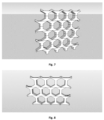
- the arrangement includes at least two interconnected structural elements 1 that are stacked on top of each other and side by side as shown in Fig. 4 -8 .
- the structural elements 1 are connected horizontally to each other in the direction perpendicular to the Z-axis by means of contact surfaces, which consist of the lower contact surface 5a of the groove 5, the upper contact surface 6a of the tongues 6, and the upper surface of the head 3b.
- Structural elements 1 arranged horizontally next to each other adhere to each other with their perpendicular surfaces 6b and lean against each other.
- the structural elements 1 are connected to each other by the upper surfaces of the head 3b and the lower contact surfaces 5a of the groove 5, which are in contact with the upper contact surfaces 6a of the tongues 6.
- the vertical contact surfaces of the components are the right-angle arm surface 6b of the tongue 6 and the side surface 6c of the tongue and the side surface 5b of the groove 5.
- Superimposed structural elements 1 press the structural elements 1 of the lower layer against each other.
- One structural element 1 is laid on top of two structural elements 1 arranged next to each other horizontally. This position allows the two structural elements 1 arranged next to each other horizontally to be pressed against each other by properly aligning the tongues 6 with the grooves 5.
- a well-fitted and stable structure in all directions is formed. Thanks to the structure, according to the favorable example of execution, the elements will stick to each other even without glue or mortar.
- the stacked structural elements 1 transfer vertical forces from the Z-axis of one structural element 1 to the Z-axes of two more structural elements 1 as shown in Fig. 10 .
- the connected structural elements 1 into a wall form between the side surfaces 2a of the shaft 2 together with the bottom surfaces 3a of the head 3 a hollow space in the shape of a substantially hexagonal, regular hexagon, circle or ellipse, as can be seen in Figs. 6-8 and 10-11 .
- the arrangement in another execution example includes a structural or insulating part that is configured to be placed in the created voids of the structural framework formed by the arrangement of the structural elements 1.
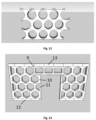
- the structural part of the wall or insulating part is an insulating brick 8, as seen in Fig. 13 , made of insulating materials for example Styrofoam.
- Fig. 12 shows a wall, which is the subject of the invention, using structural elements 1.
- the wall includes starting elements 12 and ending elements 13.
- Starting elements 12 and ending elements 13 contain some features of structural element 1, at least grooves 5 and tongues 6.
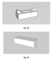
- Starting elements 12 and ending elements 13 in this example of execution have the same geometry and can be seen in Figs. 18 and 19 .
- the wall includes a system lintel 9, side elements 10 and vertical beams 11.
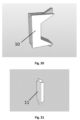
- Fig. 20 shows an example of the execution of side element 10
- Fig. 21 shows an example of the execution of vertical beam 11.
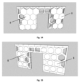
- Fig. 14 shows such a wall from the outside of the building with insulating bricks 8 filled in.
- the wall from the outside can be covered with a thin-coat facade plaster, or it can be already finished insulating bricks 8 that are also a facade.
- Fig. 15 shows the wall from the inside.
- the wall from the inside can be finished in any way, for example, with plaster on a grid or with gypsum boards. Additional layers of thermal or acoustic insulation can be applied to the wall.
- insulating bricks 8 can have different insulation and water vapor permeability parameters.
- the same wall can be insulated with insulating bricks 8 made of different materials. For example, at the ground of the wall can be insulated with insulating bricks 8 resistant to moisture. At the top of the wall, water vapor permeable bricks can be placed. This is a unique property of the wall based on the presented construction not available in alternative wall construction systems, including frame wall construction.
Landscapes
- Engineering & Computer Science (AREA)
- Architecture (AREA)
- Civil Engineering (AREA)
- Structural Engineering (AREA)
- Physics & Mathematics (AREA)
- Electromagnetism (AREA)
- Load-Bearing And Curtain Walls (AREA)
- Joining Of Building Structures In Genera (AREA)
Claims (14)
- Ein Konstruktionselement (1) in Form einer Säule für den architektonischen Aufbau von Gebäudeskelettwänden, welcher Folgendes umfasst:- einen Schaft (2) in Form eines vertikalen Stützbalkens, wobei der Schaft (2) eine untere Kontaktfläche (2b) aufweist;- einen Kopf (3), der mit dem oberen Teil des Schafts (2) verbunden ist, wobei sich dieser Kopf (3) im Wesentlichen horizontal, senkrecht zur Z-Achse des Schafts (2) und symmetrisch zum Schaft (2) in mindestens zwei entgegengesetzten Richtungen erstreckt und mindestens zwei Seitenarme (4) bildet, und von oben umfasst der Kopf (3) die obere Fläche des Kopfes (3b);dadurch gekennzeichnet, dass der Kopf (3) mindestens zwei Vorstöße (6) auf der oberen Fläche des Kopfes (3b) aufweist, die eine obere Kontaktfläche (6a) an der Oberseite aufweisen und im Allgemeinen an den Kanten (3c) des Kopfes (3) angeordnet sind, und mindestens zwei Nuten (5) die am Boden eine untere Kontaktfläche (5a) aufweisen, wobei die Nuten (5) im Allgemeinen in der Mitte der oberen Fläche des Kopfes (3b) angeordnet sind und die Form eines jeden Vorstoßes (6) der Form jeder Nut (5) entspricht.
- Das Konstruktionselement (1) nach Anspruch 1, dadurch gekennzeichnet, dass die Vorstöße (6) ein rechtwinkliges Dreiecksprofil aufweisen, wobei eine der Flächen-Katheten (6b) der Vorstöße (6) senkrecht zur Fläche des oberen Kopfes (3b) ist.
- Das Konstruktionselement (1) nach Anspruch 1 oder 2, dadurch gekennzeichnet, dass die obere Kontaktfläche (6a) einen Winkel von 30° zur Horizontalen oder zur oberen Kopffläche (3b) bildet und/oder die untere Kontaktfläche (5a) einen Winkel von 30° zur oberen Kopffläche (3b) bildet, und der Kopf (3) eine untere Ebene (3a) aufweist, wobei die untere Ebene (3a) mit der Z-Achse des Schafts (2) einen stumpfen Winkel, vorzugsweise 120°, bildet.
- Das Konstruktionselement (1) nach einem der Ansprüche 1 bis 3, dadurch gekennzeichnet, dass mindestens zwei Nuten (5) miteinander verbunden sind und eine einzige Doppelnut bilden.
- Das Konstruktionselement (1) nach einem der Ansprüche 1 bis 4, dadurch gekennzeichnet, dass die Dicke des Vorstoßes (6) im Wesentlichen gleich der Dicke ist, die nach folgender Formel berechnet wird:
 wobei x der Wert der Neigung der oberen Kontaktfläche (6a) in Bezug auf den Schaft (2) ist, y die Gesamtbreite des Konstruktionselements (1) ist,G die Dicke des Vorstoßes (6) ist.
- Das Konstruktionselement (1) nach einem der Ansprüche 1 bis 5, dadurch gekennzeichnet, dass zwei Vorstöße (6) entweder über die Kanten des Kopfes (3) hinausragen oder nicht über die Kanten des Kopfes (3) hinausragen und diese nicht berühren.
- Das Konstruktionselement (1) nach einem der Ansprüche 1 bis 6, dadurch gekennzeichnet, dass der Schaft (2) allgemein quaderförmig, kubisch oder zylindrisch ist und vorzugsweise zusätzliche Öffnungen (7) aufweist, die zum Einsetzen von Elementen geeignet sind, und/oder die Seitenfläche (2a) des Schafts (2) mit der unteren Ebene (3a) des Kopfes (3) einen Bogen bildet.
- Das Konstruktionselement (1) gemäß einem der Ansprüche 1 bis 7, dadurch gekennzeichnet, dass die Abmessungen des Konstruktionselements (1) wie folgt sind: maximale Breite 40 cm, maximale Höhe 40 cm, maximale Dicke 20 cm und maximales Gewicht des Konstruktionselements (1) 30 kg, und es besteht aus Beton, Gips, Keramik, Polymer oder Verbundwerkstoff.
- Das Konstruktionselement (1) gemäß einem der Ansprüche 1 bis 8, dadurch gekennzeichnet, dass es aus zwei Konstruktionselementen (1) aufgebaut ist, die durch die unteren Kontaktflächen (2b) gemäß Anspruch 1 verbunden sind, um ein säulenförmiges Element mit zwei Köpfen zu bilden.
- Anordnung für den Bau einer Rahmenwand eines Rahmenhauses, bestehend aus mindestens zwei Konstruktionselementen (1) gemäß den Ansprüchen 1-9, die so konfiguriert sind, dass sie vertikal und horizontal zueinander positioniert werden können, vorzugsweise umfasst die Anordnung auch ein Konstruktions- oder Dämmteil, das so gestaltet ist, dass es in den leeren Raum zwischen den Konstruktionselementen (1) in Form eines Dämmziegelsteins (8) eingesetzt werden kann, vorzugsweise in Form eines Sechsecks, regelmäßigen Sechsecks, Kreises oder einer Ellipse, wobei der Dämmziegelstein (8) vorzugsweise aus Isoliermaterialien, z. B. Polystyrol, besteht.
- Die Rahmenwand eines Rahmenhauses ist dadurch gekennzeichnet, dass sie mindestens zwei Konstruktionselemente (1) gemäß den Ansprüchen 1-9 enthält, wobei die Vorstöße (6) horizontal durch die Flächen-Katheten (6b) und vertikal durch die oberen Kopfflächen (3b) und die unteren Kontaktflächen (5a) verbunden sind, die mit den oberen Kontaktflächen (6a) verbunden sind.
- Die Rahmenwand eines Rahmenhauses gemäß Anspruch 11, dadurch gekennzeichnet, dass sie Konstruktionselemente (1) gemäß den Ansprüchen 1 bis 9 enthält, die vorzugsweise zwischen den Ausgangselementen (12) und den Endelementen (13) und/oder Systemstürzen (9), Seitenelementen (10) und vertikalen Balken (11) angeordnet sind.
- Die Rahmenwand eines Rahmenhauses gemäß Anspruch 11 oder 12, dadurch gekennzeichnet, dass die Verbindungen der Konstruktionselemente (1) mit einem Bindemittel und/oder Bewährungs- und/oder Montageelementen verstärkt sind.
- Die Rahmenwand eines Rahmenhauses gemäß den Ansprüchen 11, 12 oder 13, dadurch gekennzeichnet, dass sie zusätzlich ein Konstruktions- oder Dämmteil in Form eines Dämmziegelsteins (8) umfasst, der vorzugsweise als vorgefertigtes Außenfassadenelement des Gebäudes konfiguriert ist.
Priority Applications (9)
| Application Number | Priority Date | Filing Date | Title |
|---|---|---|---|
| ES23461552T ES3037590T3 (en) | 2023-04-07 | 2023-04-07 | Structural element, layout and wall for architectural construction, especially frame houses |
| PL23461552.4T PL4442919T3 (pl) | 2023-04-07 | 2023-04-07 | Element konstrukcyjny, układ oraz ściana do budowy architektonicznej, zwłaszcza domów szkieletowych |
| EP23461552.4A EP4442919B1 (de) | 2023-04-07 | 2023-04-07 | Bauelement, anordnung und wand für den architektonischen aufbau, insbesondere rahmenhäuser |
| KR1020257034863A KR20250166990A (ko) | 2023-04-07 | 2024-03-28 | 건축 시공, 특히 골조 주택을 위한 구조체, 배치 및 벽 |
| PCT/EP2024/058625 WO2024208742A1 (en) | 2023-04-07 | 2024-03-28 | Structural element, layout and wall for architectural construction, especially frame houses |
| JP2025558133A JP2026511965A (ja) | 2023-04-07 | 2024-03-28 | 建築施工用、特に枠組構造住宅用の構造部材、構成、及び壁 |
| AU2024253807A AU2024253807A1 (en) | 2023-04-07 | 2024-03-28 | Structural element, layout and wall for architectural construction, especially frame houses |
| US19/469,940 US20260117516A1 (en) | 2023-04-07 | 2024-03-28 | Structural element, layout and wall for architectural construction, especially frame houses |
| CN202480021768.9A CN120936775B (zh) | 2023-04-07 | 2024-03-28 | 用于建筑学构建尤其是框架式房屋的结构构件、铺设及墙 |
Applications Claiming Priority (1)
| Application Number | Priority Date | Filing Date | Title |
|---|---|---|---|
| EP23461552.4A EP4442919B1 (de) | 2023-04-07 | 2023-04-07 | Bauelement, anordnung und wand für den architektonischen aufbau, insbesondere rahmenhäuser |
Publications (3)
| Publication Number | Publication Date |
|---|---|
| EP4442919A1 EP4442919A1 (de) | 2024-10-09 |
| EP4442919C0 EP4442919C0 (de) | 2025-06-11 |
| EP4442919B1 true EP4442919B1 (de) | 2025-06-11 |
Family
ID=86382756
Family Applications (1)
| Application Number | Title | Priority Date | Filing Date |
|---|---|---|---|
| EP23461552.4A Active EP4442919B1 (de) | 2023-04-07 | 2023-04-07 | Bauelement, anordnung und wand für den architektonischen aufbau, insbesondere rahmenhäuser |
Country Status (9)
| Country | Link |
|---|---|
| US (1) | US20260117516A1 (de) |
| EP (1) | EP4442919B1 (de) |
| JP (1) | JP2026511965A (de) |
| KR (1) | KR20250166990A (de) |
| CN (1) | CN120936775B (de) |
| AU (1) | AU2024253807A1 (de) |
| ES (1) | ES3037590T3 (de) |
| PL (1) | PL4442919T3 (de) |
| WO (1) | WO2024208742A1 (de) |
Family Cites Families (11)
| Publication number | Priority date | Publication date | Assignee | Title |
|---|---|---|---|---|
| FR961163A (de) * | 1950-05-06 | |||
| GB557353A (en) * | 1942-03-09 | 1943-11-17 | Armand Wilmshurst Soden | Improvements in buildings |
| FR2573110B1 (fr) * | 1984-11-09 | 1987-07-31 | Entreprises Const Soc Gen | Procede de construction d'un batiment a ossature legere avec parement exterieur, brique destinee a ce parement, paroi et ossature realisees selon ce procede. |
| ATE475755T1 (de) * | 2002-07-10 | 2010-08-15 | Trapani Agostino Di | Bauelement |
| US7765744B2 (en) * | 2006-12-15 | 2010-08-03 | Global Shelter Systems, Inc. | Construction block |
| PT105009A (pt) * | 2010-03-09 | 2011-09-09 | Antonio Jose Vieira Da Cunha | Bloco para construção de sistemas de fundação e método para construir muros com o referido bloco |
| CN203080532U (zh) * | 2012-11-28 | 2013-07-24 | 同济大学建筑设计研究院(集团)有限公司 | 一种蜂窝形砌块 |
| DE202015003994U1 (de) * | 2015-06-02 | 2015-07-06 | Kann Gmbh Baustoffwerke | Bauelement, insbesondere zur Errichtung von Pfeilern |
| GB2555406B (en) * | 2016-10-25 | 2022-09-28 | Biohm Ltd | An architectural structure |
| CN110145023B (zh) * | 2019-06-25 | 2024-10-22 | 安徽建筑大学 | 一种预制装配式混凝土矩形梁柱连接节点 |
| CN115419215B (zh) * | 2022-10-11 | 2024-04-16 | 中铁十一局集团有限公司 | 一种装配式构造柱施工方法 |
-
2023
- 2023-04-07 EP EP23461552.4A patent/EP4442919B1/de active Active
- 2023-04-07 ES ES23461552T patent/ES3037590T3/es active Active
- 2023-04-07 PL PL23461552.4T patent/PL4442919T3/pl unknown
-
2024
- 2024-03-28 CN CN202480021768.9A patent/CN120936775B/zh active Active
- 2024-03-28 AU AU2024253807A patent/AU2024253807A1/en active Pending
- 2024-03-28 KR KR1020257034863A patent/KR20250166990A/ko active Pending
- 2024-03-28 WO PCT/EP2024/058625 patent/WO2024208742A1/en not_active Ceased
- 2024-03-28 US US19/469,940 patent/US20260117516A1/en active Pending
- 2024-03-28 JP JP2025558133A patent/JP2026511965A/ja active Pending
Also Published As
| Publication number | Publication date |
|---|---|
| AU2024253807A1 (en) | 2025-10-23 |
| CN120936775A (zh) | 2025-11-11 |
| CN120936775B (zh) | 2026-08-11 |
| EP4442919C0 (de) | 2025-06-11 |
| ES3037590T3 (en) | 2025-10-03 |
| JP2026511965A (ja) | 2026-04-14 |
| PL4442919T3 (pl) | 2025-09-01 |
| EP4442919A1 (de) | 2024-10-09 |
| KR20250166990A (ko) | 2025-11-28 |
| WO2024208742A1 (en) | 2024-10-10 |
| US20260117516A1 (en) | 2026-04-30 |
Similar Documents
| Publication | Publication Date | Title |
|---|---|---|
| US9523201B2 (en) | Construction components having embedded internal support structures to provide enhanced structural reinforcement for, and improved ease in construction of, walls comprising same | |
| EP0454690B1 (de) | Vorgefertigtes gebäudefundamentelement | |
| US9404234B2 (en) | Building block system | |
| US6324812B1 (en) | Method and kit for monolithic construction of metal fiber reinforced concrete formed by corrugated foam panels | |
| US5617686A (en) | Insulating polymer wall panels | |
| US6009677A (en) | Building panels for use in the construction of buildings | |
| US9487943B2 (en) | Component building system | |
| US20170191266A1 (en) | A self-bearing prefabricated construction element and a method of erecting external building walls of prefabricated construction elements | |
| JP2019509415A5 (de) | ||
| US4903453A (en) | Construction blocks | |
| EP4442919A1 (de) | Bauelement, anordnung und wand für den architektonischen aufbau, insbesondere rahmenhäuser | |
| GB2140053A (en) | Building system | |
| CN205935403U (zh) | 蜂窝材料人字梁序列结构及其形成的无檩柁屋架结构 | |
| RU2597651C1 (ru) | Перекрытие деревянное и плита деревянная для этого перекрытия | |
| RU2137887C1 (ru) | Стеновое ограждение | |
| RU52053U1 (ru) | Здание | |
| CA1273217A (en) | Building system | |
| TW201037132A (en) | Steel-reinforced concrete building strcture and method thereof | |
| JP5806033B2 (ja) | 組積造建物の臥梁用の外枠材、及び組積造建物 | |
| EP0185805A1 (de) | Bausystem | |
| CA2367949C (en) | Paraseismic monolithic concrete construction | |
| CN110725465A (zh) | 三维砌块 | |
| Mironov et al. | FRAME AND WOODEN FRAME CONSTRUCTION IN RUSSIA | |
| RO113264B1 (ro) | Constructie cu structura usoara | |
| CZ13684U1 (cs) | Velkoplošný stěnový panel a stavba vytvořená s jeho použitím |
Legal Events
| Date | Code | Title | Description |
|---|---|---|---|
| PUAI | Public reference made under article 153(3) epc to a published international application that has entered the european phase |
Free format text: ORIGINAL CODE: 0009012 |
|
| STAA | Information on the status of an ep patent application or granted ep patent |
Free format text: STATUS: REQUEST FOR EXAMINATION WAS MADE |
|
| 17P | Request for examination filed |
Effective date: 20231129 |
|
| AK | Designated contracting states |
Kind code of ref document: A1 Designated state(s): AL AT BE BG CH CY CZ DE DK EE ES FI FR GB GR HR HU IE IS IT LI LT LU LV MC ME MK MT NL NO PL PT RO RS SE SI SK SM TR |
|
| GRAP | Despatch of communication of intention to grant a patent |
Free format text: ORIGINAL CODE: EPIDOSNIGR1 |
|
| STAA | Information on the status of an ep patent application or granted ep patent |
Free format text: STATUS: GRANT OF PATENT IS INTENDED |
|
| RIC1 | Information provided on ipc code assigned before grant |
Ipc: E04C 2/00 20060101ALN20241119BHEP Ipc: E04B 2/56 20060101ALI20241119BHEP Ipc: E04C 2/04 20060101ALI20241119BHEP Ipc: E04B 2/64 20060101ALI20241119BHEP Ipc: E04C 3/34 20060101ALI20241119BHEP Ipc: E04B 2/50 20060101AFI20241119BHEP |
|
| INTG | Intention to grant announced |
Effective date: 20241204 |
|
| GRAS | Grant fee paid |
Free format text: ORIGINAL CODE: EPIDOSNIGR3 |
|
| GRAA | (expected) grant |
Free format text: ORIGINAL CODE: 0009210 |
|
| STAA | Information on the status of an ep patent application or granted ep patent |
Free format text: STATUS: THE PATENT HAS BEEN GRANTED |
|
| AK | Designated contracting states |
Kind code of ref document: B1 Designated state(s): AL AT BE BG CH CY CZ DE DK EE ES FI FR GB GR HR HU IE IS IT LI LT LU LV MC ME MK MT NL NO PL PT RO RS SE SI SK SM TR |
|
| REG | Reference to a national code |
Ref country code: GB Ref legal event code: FG4D |
|
| REG | Reference to a national code |
Ref country code: CH Ref legal event code: EP |
|
| REG | Reference to a national code |
Ref country code: DE Ref legal event code: R096 Ref document number: 602023003976 Country of ref document: DE |
|
| REG | Reference to a national code |
Ref country code: IE Ref legal event code: FG4D |
|
| U01 | Request for unitary effect filed |
Effective date: 20250703 |
|
| U07 | Unitary effect registered |
Designated state(s): AT BE BG DE DK EE FI FR IT LT LU LV MT NL PT RO SE SI Effective date: 20250725 |
|
| REG | Reference to a national code |
Ref country code: ES Ref legal event code: FG2A Ref document number: 3037590 Country of ref document: ES Kind code of ref document: T3 Effective date: 20251003 |
|
| PG25 | Lapsed in a contracting state [announced via postgrant information from national office to epo] |
Ref country code: GR Free format text: LAPSE BECAUSE OF FAILURE TO SUBMIT A TRANSLATION OF THE DESCRIPTION OR TO PAY THE FEE WITHIN THE PRESCRIBED TIME-LIMIT Effective date: 20250912 |
|
| PG25 | Lapsed in a contracting state [announced via postgrant information from national office to epo] |
Ref country code: HR Free format text: LAPSE BECAUSE OF FAILURE TO SUBMIT A TRANSLATION OF THE DESCRIPTION OR TO PAY THE FEE WITHIN THE PRESCRIBED TIME-LIMIT Effective date: 20250611 |
|
| PG25 | Lapsed in a contracting state [announced via postgrant information from national office to epo] |
Ref country code: RS Free format text: LAPSE BECAUSE OF FAILURE TO SUBMIT A TRANSLATION OF THE DESCRIPTION OR TO PAY THE FEE WITHIN THE PRESCRIBED TIME-LIMIT Effective date: 20250911 |
|
| PG25 | Lapsed in a contracting state [announced via postgrant information from national office to epo] |
Ref country code: IS Free format text: LAPSE BECAUSE OF FAILURE TO SUBMIT A TRANSLATION OF THE DESCRIPTION OR TO PAY THE FEE WITHIN THE PRESCRIBED TIME-LIMIT Effective date: 20251011 |
|
| PG25 | Lapsed in a contracting state [announced via postgrant information from national office to epo] |
Ref country code: SM Free format text: LAPSE BECAUSE OF FAILURE TO SUBMIT A TRANSLATION OF THE DESCRIPTION OR TO PAY THE FEE WITHIN THE PRESCRIBED TIME-LIMIT Effective date: 20250611 |
|
| PG25 | Lapsed in a contracting state [announced via postgrant information from national office to epo] |
Ref country code: CZ Free format text: LAPSE BECAUSE OF FAILURE TO SUBMIT A TRANSLATION OF THE DESCRIPTION OR TO PAY THE FEE WITHIN THE PRESCRIBED TIME-LIMIT Effective date: 20250611 |
|
| PG25 | Lapsed in a contracting state [announced via postgrant information from national office to epo] |
Ref country code: SK Free format text: LAPSE BECAUSE OF FAILURE TO SUBMIT A TRANSLATION OF THE DESCRIPTION OR TO PAY THE FEE WITHIN THE PRESCRIBED TIME-LIMIT Effective date: 20250611 |
|
| PLBE | No opposition filed within time limit |
Free format text: ORIGINAL CODE: 0009261 |
|
| STAA | Information on the status of an ep patent application or granted ep patent |
Free format text: STATUS: NO OPPOSITION FILED WITHIN TIME LIMIT |
|
| PGFP | Annual fee paid to national office [announced via postgrant information from national office to epo] |
Ref country code: TR Payment date: 20260317 Year of fee payment: 4 |
|
| REG | Reference to a national code |
Ref country code: CH Ref legal event code: L10 Free format text: ST27 STATUS EVENT CODE: U-0-0-L10-L00 (AS PROVIDED BY THE NATIONAL OFFICE) Effective date: 20260423 |
|
| 26N | No opposition filed |
Effective date: 20260312 |
|
| U20 | Renewal fee for the european patent with unitary effect paid |
Year of fee payment: 4 Effective date: 20260414 |
|
| PGFP | Annual fee paid to national office [announced via postgrant information from national office to epo] |
Ref country code: PL Payment date: 20260414 Year of fee payment: 4 |
|
| REG | Reference to a national code |
Ref country code: CH Ref legal event code: U11 Free format text: ST27 STATUS EVENT CODE: U-0-0-U10-U11 (AS PROVIDED BY THE NATIONAL OFFICE) Effective date: 20260710 |
|
| PGFP | Annual fee paid to national office [announced via postgrant information from national office to epo] |
Ref country code: NO Payment date: 20260416 Year of fee payment: 4 |