EP4439787A2 - Batteriepack - Google Patents
Batteriepack Download PDFInfo
- Publication number
- EP4439787A2 EP4439787A2 EP24166211.3A EP24166211A EP4439787A2 EP 4439787 A2 EP4439787 A2 EP 4439787A2 EP 24166211 A EP24166211 A EP 24166211A EP 4439787 A2 EP4439787 A2 EP 4439787A2
- Authority
- EP
- European Patent Office
- Prior art keywords
- mounting hole
- housing
- sealing member
- mounting
- battery pack
- Prior art date
- Legal status (The legal status is an assumption and is not a legal conclusion. Google has not performed a legal analysis and makes no representation as to the accuracy of the status listed.)
- Pending
Links
Images


Classifications
-
- H—ELECTRICITY
- H01—ELECTRIC ELEMENTS
- H01M—PROCESSES OR MEANS, e.g. BATTERIES, FOR THE DIRECT CONVERSION OF CHEMICAL ENERGY INTO ELECTRICAL ENERGY
- H01M50/00—Constructional details or processes of manufacture of the non-active parts of electrochemical cells other than fuel cells, e.g. hybrid cells
- H01M50/10—Primary casings; Jackets or wrappings
- H01M50/183—Sealing members
- H01M50/186—Sealing members characterised by the disposition of the sealing members
-
- H—ELECTRICITY
- H01—ELECTRIC ELEMENTS
- H01M—PROCESSES OR MEANS, e.g. BATTERIES, FOR THE DIRECT CONVERSION OF CHEMICAL ENERGY INTO ELECTRICAL ENERGY
- H01M10/00—Secondary cells; Manufacture thereof
- H01M10/42—Methods or arrangements for servicing or maintenance of secondary cells or secondary half-cells
- H01M10/48—Accumulators combined with arrangements for measuring, testing or indicating the condition of cells, e.g. the level or density of the electrolyte
-
- G—PHYSICS
- G01—MEASURING; TESTING
- G01K—MEASURING TEMPERATURE; MEASURING QUANTITY OF HEAT; THERMALLY-SENSITIVE ELEMENTS NOT OTHERWISE PROVIDED FOR
- G01K1/00—Details of thermometers not specially adapted for particular types of thermometer
- G01K1/14—Supports; Fastening devices; Arrangements for mounting thermometers in particular locations
-
- H—ELECTRICITY
- H01—ELECTRIC ELEMENTS
- H01M—PROCESSES OR MEANS, e.g. BATTERIES, FOR THE DIRECT CONVERSION OF CHEMICAL ENERGY INTO ELECTRICAL ENERGY
- H01M10/00—Secondary cells; Manufacture thereof
- H01M10/42—Methods or arrangements for servicing or maintenance of secondary cells or secondary half-cells
- H01M10/48—Accumulators combined with arrangements for measuring, testing or indicating the condition of cells, e.g. the level or density of the electrolyte
- H01M10/482—Accumulators combined with arrangements for measuring, testing or indicating the condition of cells, e.g. the level or density of the electrolyte for several batteries or cells simultaneously or sequentially
-
- H—ELECTRICITY
- H01—ELECTRIC ELEMENTS
- H01M—PROCESSES OR MEANS, e.g. BATTERIES, FOR THE DIRECT CONVERSION OF CHEMICAL ENERGY INTO ELECTRICAL ENERGY
- H01M10/00—Secondary cells; Manufacture thereof
- H01M10/42—Methods or arrangements for servicing or maintenance of secondary cells or secondary half-cells
- H01M10/48—Accumulators combined with arrangements for measuring, testing or indicating the condition of cells, e.g. the level or density of the electrolyte
- H01M10/486—Accumulators combined with arrangements for measuring, testing or indicating the condition of cells, e.g. the level or density of the electrolyte for measuring temperature
-
- H—ELECTRICITY
- H01—ELECTRIC ELEMENTS
- H01M—PROCESSES OR MEANS, e.g. BATTERIES, FOR THE DIRECT CONVERSION OF CHEMICAL ENERGY INTO ELECTRICAL ENERGY
- H01M50/00—Constructional details or processes of manufacture of the non-active parts of electrochemical cells other than fuel cells, e.g. hybrid cells
- H01M50/20—Mountings; Secondary casings or frames; Racks, modules or packs; Suspension devices; Shock absorbers; Transport or carrying devices; Holders
- H01M50/204—Racks, modules or packs for multiple batteries or multiple cells
-
- H—ELECTRICITY
- H01—ELECTRIC ELEMENTS
- H01M—PROCESSES OR MEANS, e.g. BATTERIES, FOR THE DIRECT CONVERSION OF CHEMICAL ENERGY INTO ELECTRICAL ENERGY
- H01M50/00—Constructional details or processes of manufacture of the non-active parts of electrochemical cells other than fuel cells, e.g. hybrid cells
- H01M50/20—Mountings; Secondary casings or frames; Racks, modules or packs; Suspension devices; Shock absorbers; Transport or carrying devices; Holders
- H01M50/204—Racks, modules or packs for multiple batteries or multiple cells
- H01M50/207—Racks, modules or packs for multiple batteries or multiple cells characterised by their shape
- H01M50/213—Racks, modules or packs for multiple batteries or multiple cells characterised by their shape adapted for cells having curved cross-section, e.g. round or elliptic
-
- H—ELECTRICITY
- H01—ELECTRIC ELEMENTS
- H01M—PROCESSES OR MEANS, e.g. BATTERIES, FOR THE DIRECT CONVERSION OF CHEMICAL ENERGY INTO ELECTRICAL ENERGY
- H01M50/00—Constructional details or processes of manufacture of the non-active parts of electrochemical cells other than fuel cells, e.g. hybrid cells
- H01M50/20—Mountings; Secondary casings or frames; Racks, modules or packs; Suspension devices; Shock absorbers; Transport or carrying devices; Holders
- H01M50/233—Mountings; Secondary casings or frames; Racks, modules or packs; Suspension devices; Shock absorbers; Transport or carrying devices; Holders characterised by physical properties of casings or racks, e.g. dimensions
- H01M50/24—Mountings; Secondary casings or frames; Racks, modules or packs; Suspension devices; Shock absorbers; Transport or carrying devices; Holders characterised by physical properties of casings or racks, e.g. dimensions adapted for protecting batteries from their environment, e.g. from corrosion
-
- H—ELECTRICITY
- H01—ELECTRIC ELEMENTS
- H01M—PROCESSES OR MEANS, e.g. BATTERIES, FOR THE DIRECT CONVERSION OF CHEMICAL ENERGY INTO ELECTRICAL ENERGY
- H01M50/00—Constructional details or processes of manufacture of the non-active parts of electrochemical cells other than fuel cells, e.g. hybrid cells
- H01M50/20—Mountings; Secondary casings or frames; Racks, modules or packs; Suspension devices; Shock absorbers; Transport or carrying devices; Holders
- H01M50/244—Secondary casings; Racks; Suspension devices; Carrying devices; Holders characterised by their mounting method
-
- H—ELECTRICITY
- H01—ELECTRIC ELEMENTS
- H01M—PROCESSES OR MEANS, e.g. BATTERIES, FOR THE DIRECT CONVERSION OF CHEMICAL ENERGY INTO ELECTRICAL ENERGY
- H01M50/00—Constructional details or processes of manufacture of the non-active parts of electrochemical cells other than fuel cells, e.g. hybrid cells
- H01M50/20—Mountings; Secondary casings or frames; Racks, modules or packs; Suspension devices; Shock absorbers; Transport or carrying devices; Holders
- H01M50/262—Mountings; Secondary casings or frames; Racks, modules or packs; Suspension devices; Shock absorbers; Transport or carrying devices; Holders with fastening means, e.g. locks
-
- H—ELECTRICITY
- H01—ELECTRIC ELEMENTS
- H01M—PROCESSES OR MEANS, e.g. BATTERIES, FOR THE DIRECT CONVERSION OF CHEMICAL ENERGY INTO ELECTRICAL ENERGY
- H01M50/00—Constructional details or processes of manufacture of the non-active parts of electrochemical cells other than fuel cells, e.g. hybrid cells
- H01M50/20—Mountings; Secondary casings or frames; Racks, modules or packs; Suspension devices; Shock absorbers; Transport or carrying devices; Holders
- H01M50/262—Mountings; Secondary casings or frames; Racks, modules or packs; Suspension devices; Shock absorbers; Transport or carrying devices; Holders with fastening means, e.g. locks
- H01M50/264—Mountings; Secondary casings or frames; Racks, modules or packs; Suspension devices; Shock absorbers; Transport or carrying devices; Holders with fastening means, e.g. locks for cells or batteries, e.g. straps, tie rods or peripheral frames
-
- H—ELECTRICITY
- H01—ELECTRIC ELEMENTS
- H01M—PROCESSES OR MEANS, e.g. BATTERIES, FOR THE DIRECT CONVERSION OF CHEMICAL ENERGY INTO ELECTRICAL ENERGY
- H01M2200/00—Safety devices for primary or secondary batteries
- H01M2200/10—Temperature sensitive devices
-
- Y—GENERAL TAGGING OF NEW TECHNOLOGICAL DEVELOPMENTS; GENERAL TAGGING OF CROSS-SECTIONAL TECHNOLOGIES SPANNING OVER SEVERAL SECTIONS OF THE IPC; TECHNICAL SUBJECTS COVERED BY FORMER USPC CROSS-REFERENCE ART COLLECTIONS [XRACs] AND DIGESTS
- Y02—TECHNOLOGIES OR APPLICATIONS FOR MITIGATION OR ADAPTATION AGAINST CLIMATE CHANGE
- Y02E—REDUCTION OF GREENHOUSE GAS [GHG] EMISSIONS, RELATED TO ENERGY GENERATION, TRANSMISSION OR DISTRIBUTION
- Y02E60/00—Enabling technologies; Technologies with a potential or indirect contribution to GHG emissions mitigation
- Y02E60/10—Energy storage using batteries
Definitions
- aspects of embodiments of the present disclosure relate to a battery pack.
- a secondary battery is designed to be charged and discharged, unlike a primary battery that is not designed to be charged.
- Secondary batteries are used as energy sources for mobile devices, electric vehicles, hybrid vehicles, electric bicycles, uninterruptible power supplies, etc.
- the secondary batteries may be used in the form of a single battery or in the form of a module in which multiple batteries are connected and bundled together into a single unit.
- Small mobile devices such as mobile phones, may operate for a certain amount of time with the output and capacity of a single battery.
- a module including a plurality of batteries is preferred due to the output and capacity characteristics.
- the output voltage or output current may be increased by increasing the number of batteries included in the module.
- a battery pack includes a sealing member provided around a periphery of a mounting hole in a housing in which a temperature measuring sensor for detecting a temperature of a battery cell is mounted, thereby blocking the inflow of foreign substances through the mounting hole.
- a battery pack includes a temperature measuring sensor for detecting the temperature of battery cells.
- the temperature measuring sensor enters an accommodation space inside the housing where the plurality of battery cells are accommodated from the outside of the housing. Due to a positional alignment between the temperature measuring sensor, the adjacent housing, and sealing member, the sealing member is positioned along the periphery of the mounting hole in the housing by at least a part of the temperature measuring sensor that enters the housing, and thus, the sealing characteristics may be improved.
- a battery pack includes: a plurality of battery cells; a housing accommodating the plurality of battery cells; a temperature measuring sensor extending from outside the housing to inside the housing along an axial direction by passing through a mounting hole in the housing, the temperature measuring sensor including: a pillar part extending along the axial direction; a locking jaw member extending from a lower position of the pillar part to an upper position toward the housing along the axial direction, extending to follow both the axial direction and a crossing direction crossing the axial direction, and providing an elastic bias force along the crossing direction away from the pillar part with respect to the mounting hole in the housing; and an expansion part expanding from a circumference of the pillar part to cover the mounting hole at an upper portion of the mounting hole along the axial direction; and a sealing member between the expansion part of the temperature measuring sensor and the housing and surrounding the mounting hole.
- the locking jaw member may include: a fixing part fixed to the lower position of the pillar part; an elastic part extending upwardly from the fixing part to follow both the axial direction and the crossing direction; a hooking part having a stepped surface extending upwardly from the elastic part and supporting a corner of the housing around the mounting hole; and a mounting part extending upwardly from the hooking part and inserted into and fixed to a periphery of the mounting hole.
- the stepped surface may be formed by a thickness difference between the hooking part and the mounting part at one end of the hooking part.
- the stepped surface and the mounting part which may extend from an inner position adjacent to the pillar part on the stepped surface, may together surround the corner of the housing around the mounting hole.
- the fixing part and hooking part connected to both ends of the elastic part may have a rounded joint forming an elastic connection.
- the elastic part and the hooking part may each have an oblique contour that follows both the axial direction and the crossing direction.
- the elastic part and the hooking part may each have an oblique contour extending with substantially same slope.
- the mounting part may provide an elastic bias force tending to expand the mounting part toward the periphery of the mounting hole, and the mounting part may extend along a direction relatively closer to the axial direction than an extension direction of the elastic part and the hooking part.
- the expansion part may have a disk shape extending from the circumference of the pillar part.
- the sealing member may be between an outer surface of the housing and the expansion part on the outer surface of the housing opposite to the plurality of battery cells.
- the sealing member may include a concentric inner wall and an outer wall surrounding the mounting hole at different inner and outer positions to provide double sealing of the mounting hole.
- the sealing member may have an annular separation groove separating the inner wall and the outer wall from each other in at least one of an upper surface of the sealing member facing the expansion part and a lower surface of the sealing member facing the housing.
- the locking jaw member may include a mounting part in close contact with a periphery of the mounting hole and an inner wall of the sealing member while providing an outwardly elastic bias force with respect to the periphery of the mounting hole and the inner wall of the sealing member.
- the mounting part may include: a lower portion fitted into the mounting hole and forcibly contacting the mounting hole; and an upper portion forcibly contacting the inner wall of the sealing member.
- the temperature measuring sensor and the sealing member may be aligned with respect to the mounting hole due to the elastic bias force of the mounting part.
- the locking jaw member may include a pair of locking jaw members on opposite sides of the pillar part.
- the pair of locking jaw members may provide an outwardly elastic bias force toward a periphery of the mounting hole, and the temperature measuring sensor may be configured to be attached to or detached from the mounting hole by providing a pressing force to the pair of locking jaw members toward the pillar part or releasing the pressing force.
- a contact surface between the locking jaw member and the mounting hole and the sealing member may be a non-adhesive surface.
- the pillar part may include a lower end extending toward one of the battery cells.
- the lower end of the pillar part and the one of the battery cells may contact each other through a thermal interference material, and the thermal interference material may provide forced contact with the one of the battery cells while being adhered to the lower end of the pillar part.
- the one of the battery cells may have first and second end surfaces on which first and second electrodes are respectively formed and a cylindrical side extending between the first and second end surfaces, and the lower end of the pillar part may have a concave curved surface matching the cylindrical side of the one of the battery cells.
- the expression "at least one of a, b, or c" indicates only a, only b, only c, both a and b, both a and c, both b and c, all of a, b, and c, or variations thereof.
- the terms “use,” “using,” and “used” may be considered synonymous with the terms “utilize,” “utilizing,” and “utilized,” respectively.
- the terms “substantially,” “about,” and similar terms are used as terms of approximation and not as terms of degree, and are intended to account for the inherent variations in measured or calculated values that would be recognized by those of ordinary skill in the art.
- first, second, third, etc. may be used herein to describe various elements, components, regions, layers, and/or sections, these elements, components, regions, layers, and/or sections should not be limited by these terms. These terms are used to distinguish one element, component, region, layer, or section from another element, component, region, layer, or section. Thus, a first element, component, region, layer, or section discussed below could be termed a second element, component, region, layer, or section without departing from the teachings of example embodiments.
- spatially relative terms such as “beneath,” “below,” “lower,” “above,” “upper,” and the like, may be used herein for ease of description to describe one element or feature's relationship to another element(s) or feature(s) as illustrated in the figures. It will be understood that the spatially relative terms are intended to encompass different orientations of the device in use or operation in addition to the orientation depicted in the figures. For example, if the device in the figures is turned over, elements described as “below” or “beneath” other elements or features would then be oriented “above” or “over” the other elements or features. Thus, the term “below” may encompass both an orientation of above and below. The device may be otherwise oriented (rotated 90 degrees or at other orientations), and the spatially relative descriptors used herein should be interpreted accordingly.
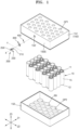
- the battery pack may include a plurality of battery cells 10, a housing 150 accommodating the battery cells 10, a temperature measuring sensor 200, and a sealing member 300.
- the temperature measuring sensor 200 may include a pillar part 210 protruding toward the plurality of battery cells 10 and mounted through a mounting hole (e.g., a mounting opening) 150' in the housing 150 to measure a temperature of the plurality of battery cells 10, an expansion part 250 extending from a circumference of the pillar part 210 and covering the mounting hole 150', and a locking jaw member 230 extending from the pillar part 210 toward the housing 150 and fixed in the mounting hole 150' in the housing 150.
- the sealing member 300 is disposed between the expansion part 250 and the housing 150 and surrounds (e.g., extends around a circumference of) the mounting hole 150'.
- the housing 150 may include a first housing 151 and a second housing 152 assembled to face each other with the plurality of battery cells 10 disposed therebetween.
- Through-holes OP1 and OP2 respectively formed in the first housing 151 and the second housing 152 expose first and second ends 11 and 12 opposite to each other of the plurality of battery cells 10, and an assembly rib RR surrounds (e.g., surrounds at least a part of) a side 15 of the plurality of battery cells 10 to regulate (or maintain) assembly positions of the plurality of battery cells 10.
- each of the plurality of battery cells 10 has first and second ends 11 and 12 opposite to each other and a side 15 connecting (or extending between) the first and second ends 11 and 12 opposite to each other.
- the plurality of battery cells 10 may be provided as cylindrical battery cells having a side 15 in the form of an outer circumferential surface.
- first and second electrode terminals having opposite polarities may be formed on the first and second ends 11 and 12 of the battery cell 10 and may be exposed to the outside of the housing 150 through through-holes (e.g., openings) OP1 and OP2 of the first and second housings 151 and 152, respectively.
- the battery cells 10 arranged adjacent to each other may be arranged so that sides 15 face each other.
- the plurality of battery cells 10 may be provided as hexagonal prismatic battery cells having a terminal surface on which electrode terminals are formed, a bottom surface disposed to face (e.g., opposite to) the terminal surface, and a side connecting (or extending between) the terminal surface and the bottom surface.
- the housing 150 may include first and second housings 151 and 152 assembled to face each other and to form an accommodation space in which the plurality of battery cells 10 are accommodated.
- the temperature measuring sensor 200 for sensing the temperature of the battery cell 10 may be disposed on one side of the housing 150 surrounding the accommodation space in which the plurality of battery cells 10 are accommodated.
- the temperature measuring sensor 200 may be selectively formed in (or selectively attached to) one of the first and second housings 151 and 152 along the third direction Z3 or may be disposed in both the first and second housings 151 and 152, respectively.
- the temperature measuring sensor 200 may be disposed on one side of the housing 150 surrounding the accommodation space, and to the extent that the temperature of the battery cell 10 in the accommodation space may be detected, may be not limited to the bar shape illustrated in the drawings and may be disposed in various places of the housing 150.
- the battery pack may include a temperature measuring sensor 200 for sensing temperatures of the plurality of battery cells 10 accommodated in the housing 150.
- the temperature measuring sensor 200 detects (or is configured to detect) the temperature of the battery cell 10 or a plurality of battery cells 10 may refer to the temperature measuring sensor 200 detecting the temperature of any one of the battery cells 10 or of ones of the battery cells 10 or detecting the temperature of one unspecified battery cell 10 or the unspecified battery cells 10.
- the temperature measuring sensor 200 may directly measure the temperature of the battery cell 10 or may measure the temperature in an accommodation space in which a plurality of battery cells 10 are accommodated and may estimate the temperature of the battery cells 10 from the temperature distribution in the accommodating space.
- the temperature measuring sensor 200 may enter toward the accommodation space inside the housing 150 through a mounting hole 150' formed in one side of the housing 150, and when the temperature measuring sensor 200 is inserted into the mounting hole 150' and fixed thereto, the temperature measuring sensor 200 may be disposed throughout the inside and outside of (e.g., may extend from the outside to the inside of) the housing 150.
- the temperature measuring sensor 200 may be elongated along the axial direction X to enter the inside of the housing 150 from the outside of the housing 150.
- the temperature measuring sensor 200 may include a pillar part 210 extending throughout the inside and outside of the housing 150 along the axial direction X, an expansion part 250 extending along the circumference of the pillar part 210 from the outside of the housing 150, and a locking jaw member 230 extending from the circumference of the pillar part 210 inside the housing 150.
- the axial direction X may refer to the longitudinal direction of the temperature measuring sensor 200 and may refer to a direction from the outside of the housing 150 to the accommodation space inside the housing 150 along the length direction of the temperature measuring sensor 200 and to approach the battery cells 10 accommodated in the accommodation space.
- the axial direction X of the temperature measuring sensor 200 may refer to a direction facing the side 15 of the battery cells 10 corresponding to a temperature measuring point.
- the temperature measuring sensor 200 may include a pillar part 210 extending along the axial direction X.
- the pillar part 210 may be formed along the axial direction X to enter the inside of the housing 150 from the outside of the housing 150 and access the accommodation space inside the housing 150, and the pillar part 210 may form the skeleton of (e.g., the structure of) the temperature measuring sensor 200. While extending along the axial direction X, the pillar part 210 may support the expansion part 250 and the locking jaw member 230 at different locations along the axial direction X.
- the axial direction X may refer to a direction in which the pillar part 210 extends, and based on one side (e.g., side 150S of the housing 150) of the housing 150 to which the temperature measuring sensor 200 is mounted and based on one side of the housing 150 that crosses between the inside where the accommodation space is formed and the outside where a part of the temperature measuring sensor 200 is exposed, may correspond to a direction perpendicular to the direction dividing the inside and outside of the housing 150.
- a temperature measuring sensor 200 according to embodiments of the present disclosure will be described in more detail with reference to FIGS. 2 to 4 .
- the temperature measuring sensor 200 will be described with the axial direction X of the temperature measuring sensor 200 being the vertical direction.
- the locking jaw member 230 may be supported at a lower position of the pillar part 210 along the pillar part 210, and the locking jaw member 230 may include a pair of locking jaw members 230 supported at opposite positions along the circumference of the pillar part 210.
- the pair of locking jaw members 230 may provide position fixation with the mounting hole 150' after being inserted into the mounting hole 150' in the housing 150 in an elastically compressed state along the mutually facing direction of the pair of locking jaw members 230 (e.g., the crossing direction Y crossing the axial direction X).
- the pair of locking jaw members 230 may be fitted into the mounting hole 150' in an elastically compressed state, and along the crossing direction Y away from each other according to the elastic restoring force, may be fixed in position in the mounting hole 150' by being in close contact with the periphery of the mounting hole 150' in an elastically biased state.
- the position of the entire temperature measuring sensor 200 including the locking jaw member 230 may be fixed.
- the locking jaw member 230 may extend from a lower position (or portion) of the pillar part 210 to an upper position toward the housing 150 along the axial direction X, and to provide an elastic bias in the crossing direction Y away from the pillar part 210, may extend away from the pillar part 210 along the crossing direction (e.g., the circumferential direction of the pillar part 210).
- the locking jaw member 230 may extend from a lower position of the pillar part 210 to an upper position toward the housing 150 as a whole along an approximate oblique direction that follows both the axial direction X and the crossing direction Y.
- the pillar part 210 may extend toward the housing 150 along the circumferential direction (e.g., the crossing direction Y) from the centrifugal axis (or axial axis) of the shaft, the pair of locking jaw members 230 are face away from each other and may be fitted in an elastically biased state within the mounting hole 150' in the housing 150.
- a circumferential direction from the center of the shaft may correspond to a crossing direction Y crossing the axial direction X.
- the locking jaw member 230 may be elastically biased in a direction away from the pillar part 210 along the crossing direction Y.
- the locking jaw member 230 may be inserted into the mounting hole 150' in a compressed state toward the pillar part 210 along the crossing direction Y, and according to the elastic bias, which tends to expand the locking jaw member 230 in the crossing direction Y toward the periphery of the mounting hole 150', the locking jaw member 230 may be fixed in position with respect to the mounting hole 150' by closely contacting the periphery of the mounting hole 150'.
- the locking jaw member 230 may include a fixing part 231 extending along the crossing direction Y from the circumference of the pillar part 210, a mounting part 237 in close contact with the periphery of the mounting hole 150', an elastic part 233 connecting (or extending between) the fixing part 231 and the mounting part 237, and a hooking part (or hook part) 235 formed between the elastic part 233 and the mounting part 237.
- the fixing part 231 may fix the temperature measuring sensor 200 supported through the locking jaw member 230 or the locking jaw member 230 to the pillar part 210 and may be formed with a thicker thickness than other members of the locking jaw member 230 to form a firm coupling with the pillar part 210.
- the fixing part 231 may be formed with a relatively thick thickness and a rounded joint J with the elastic part 233 may be included to flexibly accommodate the elastic deformation of the elastic part 233 because the load of the temperature measuring sensor 200 may be transmitted to the fixing part 231.
- the round joint J may flexibly accommodate the elastic deformation of the elastic part 233, and for example, a rounded joint J may be included so that internal stress is not concentrated while being flexibly deformed by the deformation of the elastic part 233.
- the elastic part 233 may connect between the fixing part 231 coupled to the lower position of the pillar part 210 and the mounting part 237 inserted into the mounting hole 150' and may elastically connect the fixing part 231 and the mounting part 237.
- the elastic part 233 elastically connects the fixing part 231 and the mounting part 237 and may be formed having a relatively thin thickness to flexible for elastic deformation.
- the locking jaw member 230 may be integrally formed of the same material capable of elastic deformation as a whole, and for example, elastic deformation may be allowed to the entire locking jaw member 230 including the elastic part 233, having a relatively thin thickness, and through the pillar part 210 and the elastic part 233 that excludes direct position fixation to the mounting hole 150', a relatively large amount of elastic deformation of the locking jaw member 230 may occur.
- the elastic part 233 may extend along an oblique direction to follow both the axial direction X of the pillar part 210 and the crossing direction Y corresponding to the elastic bias direction.
- the hooking part 235 may be formed between the elastic part 233 and the mounting part 237 inserted into the mounting hole 150'.
- the hooking part 235 may support the corner (or edge) C around the mounting hole 150' at the stepped surface 235a of the hooking part 235 corresponding to the thickness step between the elastic part 233 and the mounting part 237.
- the stepped surface 235a of the hooking part 235 may support the corner C around the mounting hole 150', and together with the stepped surface 235a of the hooking part 235, through the mounting part 237 in close contact with the side of the mounting hole 150', the location of the locking jaw member 230 may be firmly fixed while surrounding (e.g., continuously surrounding) the side and corner C of the mounting hole 150'.
- the stepped surface 235a of the hooking part 235 may be formed by a thickness step between the hooking part 235 and the mounting part 237, and a thickness difference may be formed between the hooking part 235 and the mounting part 237 to form the stepped surface 235a of the hooking part 235.
- the mounting part 237 extends from an inner position adjacent to the pillar part 210 along the crossing direction Y of the hooking part 235, and a thickness step between the mounting part 237 and the hooking part 235 may be formed to surround the corner C of the mounting hole 150'.
- the corner C of the mounting hole 150' may be surrounded by the stepped surface 235a corresponding to the thickness step between the mounting part 237 and the hooking part 235.
- the stepped surface 235a which supports the corner C of the mounting hole 150', may be formed at a position where the hooking part 235 and the mounting part 237 come into contact with each other at one end of the hooking part 235, and the stepped surface 235a formed on one end of the hooking part 235 and the mounting part 237 connected to one end of the hooking part 235 may be connected to each other to surround the corner C of the mounting hole 150'.
- the hooking part 235 may extend from the elastic part 233 and may be formed to have a relatively thicker thickness than the elastic part 233.
- the hooking part 235 and the mounting part 237 may be connected to each other through a stepped surface 235a corresponding to a thickness step between the hooking part 235 and the mounting part 237, and the hooking part 235 and the elastic part 233 may be connected to each other through a round joint J that smoothly connects the different thickness portions between the hooking part 235 and the elastic part 233.
- the hooking part 235 and the mounting part 237 may be connected to each other through an angled stepped surface 235a to receive an edge forming a corner C of the mounting hole 150', and the hooking part 235 and the elastic part 233 may be connected to each other through a round joint J to flexibly accommodate deformation therebetween and avoid a stress concentration.
- the hooking part 235 and the elastic part 233 may extend along the axial direction X of the pillar part 210, may extend along the crossing direction Y corresponding to the circumferential direction of the pillar part 210, and may extend along an oblique direction that follows both the axial direction X and the crossing direction Y.
- the contours of oblique lines formed at outer positions of the elastic part 233 and the hooking part 235 may extend along substantially the same inclination.
- the mounting part 237 may extend from an inner position relatively adjacent to the pillar part 210 on the stepped surface 235a forming one end of the hooking part 235, and to be in close contact with the side of the mounting hole 150', compared to the extension direction of the elastic part 233 described above, the mounting part 237 may extend generally along an inclined direction near to the axial direction X of the pillar part 210. For example, the mounting part 237 may extend more steeply along the axial direction X of the pillar part 210 compared to the extending direction of the elastic part 233.
- the mounting part 237 may fix the position of the temperature measuring sensor 200 with respect to the housing 150 by being in close contact with the mounting hole 150' formed in one side of the housing 150 and may provide physical binding (e.g., may fix) between the sealing member 300 disposed outside the housing 150 and the temperature measuring sensor 200.
- the mounting part 237 may be in close contact with the side (e.g., an inner circumferential surface) of the sealing member 300 disposed outside the housing 150 at the same time it is in close contact with the side of the mounting hole 150' formed on one side of the housing 150.
- the mounting part 237 may have a lower part in close contact with the side of the mounting hole 150' and an upper part in close contact with the side (e.g., inner circumferential surface) of the sealing member 300.
- the mounting part 237 may extend along the axial direction X of the pillar part 210.
- the lower part of the mounting part 237 adjacent to the hooking part 235 along the axial direction X may be in close contact with the side of the mounting hole 150', and an upper portion of the mounting part 237 adjacent to the expansion part 250 along the axial direction X may come into close contact with the side (e.g., the inner circumferential surface) of the sealing member 300.
- the mounting part 237 may provide binding (e.g., may fix) between the temperature measuring sensor 200 and other adjacent components, or between the housing 150 and the sealing member 300, through its lower and upper portions.
- the pillar part 210 may be formed to pass through the inside and outside of the housing 150 along the axial direction X and may be formed to pass through the inside and outside of the housing 150 through the mounting hole 150' in the housing 150.
- the pillar part 210 may have a square pillar shape having a square cross section to pass through the circular mounting hole 150'.
- the pillar part 210 may be formed into a column shape having various shapes, such as a circular cross section or a square cross section.
- the pillar part 210 may have a rectangular cross section in which a relatively short side and a relatively long side face each other, and the locking jaw member 230 may be formed at positions of opposite rotational angles along the circumference of the centrifugal axis of the shaft, for example, may be formed at a pair of short sides facing each other.
- the overall shape of the temperature measuring sensor 200 may have a long side of the rectangular cross section of the pillar part 210, a flat pillar part 210 extending from the short side along the long side direction, and an expansion part 250 formed in a disk shape from the assemblies 210 and 230 of the locking jaw member 230 and the assemblies 210 and 230 along the axial direction X.
- the locking jaw member 230 which is part of the pillar part 210 that extends through the inside and outside of the housing 150, may include a fixing part 231, an elastic part 233, and a hooking part 235 inside the housing 150, and the pillar part 210 may include an expansion part 250 outside the housing 150.
- the expansion part 250 may have an extended form along the circumference of the pillar part 210 outside the housing 150 and, for example, may have a disk shape extending along the circumference of the centrifugal axis of the shaft and may extend from (e.g., may radially extend from) the pillar part 210 along the crossing direction Y crossing the axial direction X.
- the expansion part 250 may be extended in a substantially disc shape over a range of rotational angles from the center of the shaft of the pillar part 210 along the circumference of the shaft.
- the pillar part 210 may have a columnar shape of an approximately square pillar, and the expansion part 250 may be formed in the form of a disk extending from the pillar part 210 over the entire range of rotation angles along the circumferential direction of the shaft.
- the locking jaw member 230 may not extend over the range of the entire rotation angle along the circumference of the shaft from the centrifugal center of the shaft of the pillar part 210 and may extend along the crossing direction Y from opposite rotational angular positions along the circumference of the centroid of the axis, and the expansion part 250 may be formed in a disk shape while extending over the entire range of rotation angles along the centrifugal circumference of the shaft of the pillar part 210.
- the expansion part 250 may extend along the circumference of the shaft from the centrifugal center of the shaft along the circumference of the pillar part 210 in a disk shape, may cover the upper part of the circular mounting hole 150' and may provide a mounting location for the sealing member 300.
- the sealing member 300 may be disposed outside the housing 150 in which the mounting hole 150' is formed.
- the sealing member 300 may be disposed between the outer surface of the housing 150 and the expansion part 250 outside the housing 150.
- the temperature measuring sensor 200 may extend from the outside of the housing 150 toward the inside of the housing 150 along the axial direction X and may enter the accommodation space forming the inside of the housing 150 and detect the temperature of the battery cell 10 in the accommodation space.
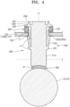
- the pillar part 210 forming the skeleton (or structure) of the temperature measuring sensor 200 may extend from the outside of the housing 150 toward the battery cell 10 accommodated inside the housing 150 along the axial direction X and may contact the outer surface of the battery cell 10.
- the lower end (or the distal end) of the pillar part 210 and the battery cell 10 may be in contact with each other via a thermal interference material (TIM) 400.
- TIM thermal interference material
- the TIM 400 may press and contact the outer surface of the battery cell 10 while being adhered to the lower end of the pillar part 210.
- the TIM 400 may be separated from the battery cell 10 by eliminating (or removing) forced contact from the battery cell 10 together with the temperature measuring sensor 200, which is detachable from the housing 150, for maintenance purposes, and contact between the TIM 400 and the battery cell 10 may be made in a non-adhesive manner (e.g., through non-adhesive surfaces) that do not depend on adhesive force.
- the lower end of the pillar part 210 may have a shape that matches or substantially matches with the outer surface of the battery cell 10 to be contacted.
- the battery cell 10 may have first and second ends (e.g., first and second end surfaces)11 and 12 on which first and second electrodes are formed, respectively, and a cylindrical side 15 connecting the first and second ends 11 and 12 and may be provided as a circular battery cell formed in a cylindrical shape overall.
- the lower end of the pillar part 210 may come into contact with the side 15 of the cylindrical shape of the battery cell 10 and may be formed in a concave curved surface shape matching the shape of the side 15 of the battery cell 10.
- the lower end of the pillar part 210 may have a curvature or a radius of curvature R corresponding to the side 15 of the battery cell 10.
- the battery cell 10 may have a substantially hexagonal shape having a terminal surface on which the first and second electrodes are formed together, a bottom surface opposite to the terminal surface, and a side that connects between the terminal surface and the bottom surface.
- the lower end of the pillar part 210 may be in contact with any one of the terminal surface, the bottom surface, and the side of the battery cell 10 and may be formed in a flat shape to match the same.
- the sealing member 300 is configured to surround the mounting hole 150' in the housing 150 to block the inflow of foreign substances through the mounting hole 150' and may be configured to seal the accommodation space inside the housing 150 by blocking the inflow of external moisture or uncontrolled external air.
- the sealing member 300 may be formed to surround the mounting hole 150' in the housing 150, and for example, a double seal may be provided to double surround the mounting hole 150'.
- the sealing member 300 may have an inner wall 301 and an outer wall 302 surrounding the mounting hole 150' at different radial positions from the centrifugal center of the mounting hole 150' to double surround (e.g., to provide two sealing surfaces around) the circumference of the mounting hole 150' at different positions.
- the periphery of the mounting hole 150' may be surrounded by the double sealing provided by the inner wall 301 and the outer wall 302.
- that the sealing member 300 includes an inner wall 301 and an outer wall 302 doubly surrounding the mounting hole 150' may refer to that the sealing member 300 is formed having a spaced apart structure from each other between the upper ends of the inner wall 301 and the outer wall 302 and between the lower ends between the inner wall 301 and the outer wall 302 through a separation groove 300' formed between the inner wall 301 and the outer wall 302.
- the inner wall 301 of the sealing member 300 may forcibly contact the locking jaw member 230 (e.g., the mounting part 237) to fix the position of the sealing member 300, and through the locking jaw member 230 (e.g., the mounting part 237) pressurized on the inner wall 301 of the sealing member 300, the inner wall 301 of the sealing member 300 may fix the position of the sealing member 300 and strengthen the sealing around the mounting hole 150'.
- the sealing member 300 may be fixed in position by being in close contact between the outer surface of the housing 150 and the expansion part 250 of the temperature measuring sensor 200 fixed in a position around the mounting hole 150'. Additional position fixing force may be provided through the mounting part 237 pressurized on the inner wall 301 of the sealing member 300.
- the sealing of the mounting hole 150' may be performed not only through double sealing of the inner wall 301 and the outer wall 302 surrounding the circumference of the mounting hole 150' but also through the locking jaw member 230 (e.g., the mounting part 237) being in close contact with the inner wall 301 such that penetration of external foreign substances, including moisture or external air of uncontrolled temperature, may be additionally blocked.
- the sealing member 300 may have a separation groove 300' extending annularly along a space between the inner wall 301 and the outer wall 302 formed in an annular concentric circle shape.
- the mounting hole 150' may be formed along a first radius from the centrifugal center of the mounting hole 150', and the inner wall 301 and the outer wall 302 of the sealing member 300 may be formed having an increased radius compared to the first radius to surround the circumference of the mounting hole 150'.
- the inner wall 301 of the sealing member 300 may be formed along a circular trajectory (or circular path) of a second radius from the centrifugal center of the mounting hole 150', and the outer wall 302 of the sealing member 300 may be formed along a circular trajectory of a third radius from the centrifugal center of the mounting hole 150'.
- the third radius of the outer wall 302 of the sealing member 300 may be larger than the second radius of the inner wall 301 of the sealing member 300, and the second radius of the inner wall 301 of the sealing member 300 may be larger than the first radius of the mounting hole 150'.
- the sealing member 300 may be disposed between the expansion part 250 and the housing 150 in an elastically compressed state, and the sealing member 300 may come into close contact between the expansion part 250 and the housing 150 according to an elastic bias that tends to expand between the expansion part 250 and the housing 150.
- the sealing member 300 may be formed of a material capable of elastic deformation, and through elastic deformation, external foreign substances may be blocked while being closely attached between the outer surface of the housing 150 and the expansion part 250 disposed vertically along the axial direction X, and the inside and outside of the housing 150 in which the mounting hole 150' is formed may be sealed from each other.
- the temperature measuring sensor 200 may be detachably assembled to the battery pack, and convenience may be enhanced in terms of maintenance, such as replacement of the temperature measuring sensor 200, through detachable assembly of the temperature measuring sensor 200.
- the temperature measuring sensor 200 may be fixed in position with respect to the mounting hole 150' by the mounting part 237 being elastically biased against the mounting hole 150', and in this case, surfaces facing each other between the mounting hole 150' and the mounting part 237 forming elastic contact with pressure may be non-adhesive surfaces without an adhesive.
- the mounting part 237 which is fixed in position with respect to the mounting hole 150', may be fixed in position with respect to each other through physical engagement with the mounting hole 150' and may not be fixed in position with respect to each other through adhesive surfaces with adhesive-like adhesiveness.
- the sealing member 300 (e.g., an inner side thereof), which forcibly contacts the mounting part 23, which is elastically biased, may also form close contact between the mounting part 237 and the sealing member 300, through physical bonding by forcible contact between the mounting part 237 and the sealing member 300 through elastic bias without forming (or including) an adhesive surface with the mounting part 237.
- the temperature measuring sensor 200 forms close contact with other components adjacent to the temperature measuring sensor 200, for example, the housing 150 and the sealing member 300, through the non-adhesive surface where an adhesive is not disposed with the housing 150 and the sealing member 300
- the sealing property may be enhanced by providing positional fixation with respect to each other or through intimate contact with each other.
- the temperature measuring sensor 200 may easily provide physical constraints from other neighboring components, and for example, through elastic deformation of the locking jaw member 230 providing an elastic bias, a physical restraint relationship between the locking jaw member 230 and other neighboring elements may be easily provided.
- the temperature measuring sensor 200 in relation to the detachment and installation of the locking jaw member 230, while the pair of locking jaw members 230 formed on opposite sides of the pillar part 210 are pressed along the direction toward each other (e.g., the crossing direction Y), the temperature measuring sensor 200 is released from the locked state with the housing 150 and may be detached from the housing 150.
- the pressure on the pair of locking jaw members 230 of the temperature measuring sensor 200 inserted into the mounting hole 150' is relieved such that a pair of locking jaw members 230 are released in a direction away from each other centering on the pillar part 210, according to the elastic bias of the locking jaw member 230, the temperature measuring sensor 200 may be mounted by the locking jaw member 230 engaging with the housing 150.
- the mounting part 237 of the temperature measuring sensor 200 by forming close contact with the temperature measuring sensor 200 and other neighboring components, for example, with the housing 150 and the sealing member 300, positional alignment of the housing 150 and the sealing member 300 with respect to each other is not required, and automatic alignment may be achieved through the mounting of the temperature measuring sensor 200.
- the sealing member 300 because the sealing member 300 surrounds the circumference of the mounting hole 150' formed in the housing 150 and blocks communication between the inside and outside of the housing 150 through the mounting hole 150', the sealing member 300 should be aligned with respect to each other in relation to the mounting hole 150', and if the centrifugal center of the mounting hole 150' and the centrifugal center of the sealing member 300 are offset from each other, for example, if the inner wall 301 or the outer wall 302 of the sealing member 300 through the mounting hole 150' is exposed, double sealing of the mounting hole 150' through the inner wall 301 and the outer wall 302 of the sealing member 300 may not be provided.
- the housing 150 and the sealing member 300 may be automatically aligned with each other by the mounting part 237.
- the sealing member 300 may be in a separate structure from the temperature measuring sensor 200, and through the sealing member 300 and the temperature measuring sensor 200 formed in a separate structure pass through the mounting part 237, for example, the mounting part 237, which is elastically biased, may provide self-alignment with respect to each other components around the mounting hole 150'.
- the temperature measuring sensor 200 and the sealing member 300 are implemented as one composite part, within the process of forming one composite part, positional alignment with respect to each other needs to be made between the temperature measuring sensor 200 and the sealing member 300, and a separate process for positional alignment may be required, and depending on the accuracy of the position between the temperature measuring sensor 200 and the sealing member 300, positional alignment with respect to each other may be misaligned. Further, due to physical interference between the temperature measuring sensor 200 and the sealing member 300, positional alignment with respect to the mounting hole 150' may be difficult in relation to the housing 150 in which the mounting hole 150' is formed.
- the temperature measuring sensor 200, the housing 150, and the sealing member 300 are formed of separate parts and may be assembled to each other and automatically aligned with each other by the mounting part 237 of the temperature measuring sensor 200, making assembly work easy, and through assembly of the individual parts, the unit cost of the individual parts may be lowered and the overall cost of the battery pack may be lowered.
- the separation groove 300' formed in the sealing member 300 may spatially separate the inner wall 301 and the outer wall 302 from each by, for example, separating the inner wall 301 and the outer wall 302 doubly surrounding the mounting hole 150' from each other along the circumferential direction from the centrifugal center of the mounting hole 150'.
- elastic deformation of the inner wall 301 and the outer wall 302 may be promoted, and for example, the inner wall 301 and the outer wall 302 may be flexibly and elastically deformed according to the pressure between the expansion part 250 and the outer surface of the housing 150, and the outer surface of the expansion part 250 and the housing 150 may be shielded.
- the separation groove 300' between the inner wall 301 and the outer wall 302 may provide a space to accommodate foreign matter penetrating from the outside and may prevent further penetration of foreign substances toward the mounting hole 150'.
- the inner wall 301 and the outer wall 302 may form a gap between the outer surface of the expansion part 250 and the housing 150 that come into contact with the upper and lower parts, and even if a foreign substance penetrates through the gap between them according to, for example, the capillary phenomenon, external foreign matter may be accommodated in the separation groove 300' formed between the inner wall 301 and the outer wall 302 and further penetration of foreign matter may be prevented.
- separation grooves 300' may be formed in the upper surface of the sealing member 300 facing the expansion part 250 and the lower surface of the sealing member 300 facing the outer surface of the housing 150, respectively.
- the separation grooves 300' may be formed on the upper and lower surfaces of the sealing member 300, respectively, and a cross section of the sealing member 300 in which the separation groove 300' is formed may be formed in an approximate H shape. Through the separation groove 300', the infiltration path of foreign substances penetrating from the outside may be blocked.
- the upper and lower surfaces of the sealing member 300 may be covered by the outer surface of the expansion part 250 and the housing 150 facing each other, and the outer surface of the expansion part 250 and the housing 150 may be formed having a sufficient area to cover the upper and lower surfaces of the sealing member 300.
- the expansion part 250 may be formed having a sufficient area to cover the outer wall 302 of the sealing member 300 from the center of the mounting hole 150', and the outer diameter of the expansion part 250 may be larger than the outer diameter of the outer wall 302 of the sealing member 300.
- the outer diameter of the expansion part 250 may protrude from (or may protrude beyond) the outer diameter of the outer wall 302 of the sealing member 300.
- a battery pack may be provided in which an inflow of external foreign substances through the mounting hole is blocked.
- a battery pack with improved sealing characteristics may be provided.
- the present disclosure is also directed to the following aspects:
Landscapes
- Chemical & Material Sciences (AREA)
- Chemical Kinetics & Catalysis (AREA)
- Electrochemistry (AREA)
- General Chemical & Material Sciences (AREA)
- Engineering & Computer Science (AREA)
- Manufacturing & Machinery (AREA)
- Physics & Mathematics (AREA)
- General Physics & Mathematics (AREA)
- Battery Mounting, Suspending (AREA)
Applications Claiming Priority (1)
| Application Number | Priority Date | Filing Date | Title |
|---|---|---|---|
| KR1020230039372A KR20240144786A (ko) | 2023-03-26 | 2023-03-26 | 배터리 팩 |
Publications (2)
| Publication Number | Publication Date |
|---|---|
| EP4439787A2 true EP4439787A2 (de) | 2024-10-02 |
| EP4439787A3 EP4439787A3 (de) | 2024-11-27 |
Family
ID=90482411
Family Applications (1)
| Application Number | Title | Priority Date | Filing Date |
|---|---|---|---|
| EP24166211.3A Pending EP4439787A3 (de) | 2023-03-26 | 2024-03-26 | Batteriepack |
Country Status (4)
| Country | Link |
|---|---|
| US (1) | US20240322326A1 (de) |
| EP (1) | EP4439787A3 (de) |
| KR (1) | KR20240144786A (de) |
| CN (1) | CN118712594A (de) |
Family Cites Families (5)
| Publication number | Priority date | Publication date | Assignee | Title |
|---|---|---|---|---|
| JP2005227027A (ja) * | 2004-02-10 | 2005-08-25 | Denso Corp | 温度センサ、温度センサ収容機構 |
| US8287185B2 (en) * | 2009-10-01 | 2012-10-16 | Delphi Technologies, Inc. | Cell temperature sensing apparatus for a battery module |
| JP5800660B2 (ja) * | 2011-10-05 | 2015-10-28 | 株式会社ニフコ | バッテリー用温度センサーの取付用クリップ |
| JP6688762B2 (ja) * | 2017-05-23 | 2020-04-28 | 矢崎総業株式会社 | 電池用温度センサ及びその取付構造 |
| US12113225B2 (en) * | 2021-04-09 | 2024-10-08 | Brunswick Corporation | Watertight marine battery |
-
2023
- 2023-03-26 KR KR1020230039372A patent/KR20240144786A/ko active Pending
-
2024
- 2024-03-20 US US18/611,048 patent/US20240322326A1/en active Pending
- 2024-03-25 CN CN202410343099.9A patent/CN118712594A/zh active Pending
- 2024-03-26 EP EP24166211.3A patent/EP4439787A3/de active Pending
Also Published As
| Publication number | Publication date |
|---|---|
| EP4439787A3 (de) | 2024-11-27 |
| US20240322326A1 (en) | 2024-09-26 |
| KR20240144786A (ko) | 2024-10-04 |
| CN118712594A (zh) | 2024-09-27 |
Similar Documents
| Publication | Publication Date | Title |
|---|---|---|
| US20210313649A1 (en) | Battery cell holder and battery system | |
| US8563165B2 (en) | Assembled battery | |
| CN1175514C (zh) | 二次电池 | |
| EP3828984B1 (de) | Batteriegehäuse | |
| EP1087456B1 (de) | Schutzvorrichtung für ein elektrisches Bauteil und Verfahren zum Zusammenbau einer Batterie mit diesem elektrischen Bauteil und der Schutzvorrichtung | |
| EP1058332B1 (de) | Stromversorgungseinheit | |
| US8512895B2 (en) | Secondary battery having an electrode terminal penetrating through and electrically insulated from a cap plate | |
| US9287546B2 (en) | Galvanic element for high stresses | |
| US8945747B2 (en) | Battery cell having an attachment structure and vehicle battery module | |
| US6673485B2 (en) | Battery module | |
| KR20080045371A (ko) | 배터리 팩 및 이의 제조 방법 | |
| JP2012513098A (ja) | リチウムイオン電池のためのモジュール式cidアセンブリ | |
| KR102913678B1 (ko) | 배터리 팩 | |
| US20150072223A1 (en) | Battery cell for electronic device | |
| EP1139702B1 (de) | Schutzvorrichtung für einen elektrischen Bauteil | |
| KR101354645B1 (ko) | 이차전지 | |
| KR20140124247A (ko) | 이차 전지 | |
| EP4439787A2 (de) | Batteriepack | |
| EP4395000A1 (de) | Batterie, verfahren und vorrichtung zur herstellung davon und elektrische vorrichtung | |
| US6426867B1 (en) | Protection device having tapered ribs and method of assembling a battery with a protection device and an electrical component | |
| CN220400853U (zh) | 用于圆柱电池的集流盘组件和圆柱电池 | |
| KR101222386B1 (ko) | 배터리팩 | |
| SE2251577A1 (en) | A cylindrical secondary cell lid or current collector disc comprising multiple recessed contact portions | |
| CN212033053U (zh) | 动力电池盖板结构及电池 | |
| CN216818490U (zh) | 一种电池托架及电池装置 |
Legal Events
| Date | Code | Title | Description |
|---|---|---|---|
| PUAI | Public reference made under article 153(3) epc to a published international application that has entered the european phase |
Free format text: ORIGINAL CODE: 0009012 |
|
| STAA | Information on the status of an ep patent application or granted ep patent |
Free format text: STATUS: REQUEST FOR EXAMINATION WAS MADE |
|
| 17P | Request for examination filed |
Effective date: 20240326 |
|
| AK | Designated contracting states |
Kind code of ref document: A2 Designated state(s): AL AT BE BG CH CY CZ DE DK EE ES FI FR GB GR HR HU IE IS IT LI LT LU LV MC ME MK MT NL NO PL PT RO RS SE SI SK SM TR |
|
| PUAL | Search report despatched |
Free format text: ORIGINAL CODE: 0009013 |
|
| AK | Designated contracting states |
Kind code of ref document: A3 Designated state(s): AL AT BE BG CH CY CZ DE DK EE ES FI FR GB GR HR HU IE IS IT LI LT LU LV MC ME MK MT NL NO PL PT RO RS SE SI SK SM TR |
|
| RIC1 | Information provided on ipc code assigned before grant |
Ipc: G01K 1/14 20210101ALI20241023BHEP Ipc: H01M 50/262 20210101ALI20241023BHEP Ipc: H01M 50/24 20210101ALI20241023BHEP Ipc: H01M 50/213 20210101ALI20241023BHEP Ipc: H01M 10/48 20060101AFI20241023BHEP |
|
| GRAP | Despatch of communication of intention to grant a patent |
Free format text: ORIGINAL CODE: EPIDOSNIGR1 |
|
| STAA | Information on the status of an ep patent application or granted ep patent |
Free format text: STATUS: GRANT OF PATENT IS INTENDED |
|
| RIC1 | Information provided on ipc code assigned before grant |
Ipc: H01M 10/48 20060101AFI20260317BHEP Ipc: H01M 50/213 20210101ALI20260317BHEP Ipc: H01M 50/24 20210101ALI20260317BHEP Ipc: H01M 50/262 20210101ALI20260317BHEP Ipc: G01K 1/14 20210101ALI20260317BHEP |