EP4395000A1 - Batterie, verfahren und vorrichtung zur herstellung davon und elektrische vorrichtung - Google Patents
Batterie, verfahren und vorrichtung zur herstellung davon und elektrische vorrichtung Download PDFInfo
- Publication number
- EP4395000A1 EP4395000A1 EP21958621.1A EP21958621A EP4395000A1 EP 4395000 A1 EP4395000 A1 EP 4395000A1 EP 21958621 A EP21958621 A EP 21958621A EP 4395000 A1 EP4395000 A1 EP 4395000A1
- Authority
- EP
- European Patent Office
- Prior art keywords
- battery
- sampling
- lead
- electrode terminal
- out portion
- Prior art date
- Legal status (The legal status is an assumption and is not a legal conclusion. Google has not performed a legal analysis and makes no representation as to the accuracy of the status listed.)
- Pending
Links
Images


Classifications
-
- H—ELECTRICITY
- H01—ELECTRIC ELEMENTS
- H01M—PROCESSES OR MEANS, e.g. BATTERIES, FOR THE DIRECT CONVERSION OF CHEMICAL ENERGY INTO ELECTRICAL ENERGY
- H01M50/00—Constructional details or processes of manufacture of the non-active parts of electrochemical cells other than fuel cells, e.g. hybrid cells
- H01M50/20—Mountings; Secondary casings or frames; Racks, modules or packs; Suspension devices; Shock absorbers; Transport or carrying devices; Holders
- H01M50/204—Racks, modules or packs for multiple batteries or multiple cells
-
- H—ELECTRICITY
- H01—ELECTRIC ELEMENTS
- H01M—PROCESSES OR MEANS, e.g. BATTERIES, FOR THE DIRECT CONVERSION OF CHEMICAL ENERGY INTO ELECTRICAL ENERGY
- H01M50/00—Constructional details or processes of manufacture of the non-active parts of electrochemical cells other than fuel cells, e.g. hybrid cells
- H01M50/50—Current conducting connections for cells or batteries
- H01M50/569—Constructional details of current conducting connections for detecting conditions inside cells or batteries, e.g. details of voltage sensing terminals
-
- H—ELECTRICITY
- H01—ELECTRIC ELEMENTS
- H01M—PROCESSES OR MEANS, e.g. BATTERIES, FOR THE DIRECT CONVERSION OF CHEMICAL ENERGY INTO ELECTRICAL ENERGY
- H01M10/00—Secondary cells; Manufacture thereof
- H01M10/42—Methods or arrangements for servicing or maintenance of secondary cells or secondary half-cells
- H01M10/48—Accumulators combined with arrangements for measuring, testing or indicating the condition of cells, e.g. the level or density of the electrolyte
- H01M10/482—Accumulators combined with arrangements for measuring, testing or indicating the condition of cells, e.g. the level or density of the electrolyte for several batteries or cells simultaneously or sequentially
-
- H—ELECTRICITY
- H01—ELECTRIC ELEMENTS
- H01M—PROCESSES OR MEANS, e.g. BATTERIES, FOR THE DIRECT CONVERSION OF CHEMICAL ENERGY INTO ELECTRICAL ENERGY
- H01M50/00—Constructional details or processes of manufacture of the non-active parts of electrochemical cells other than fuel cells, e.g. hybrid cells
- H01M50/20—Mountings; Secondary casings or frames; Racks, modules or packs; Suspension devices; Shock absorbers; Transport or carrying devices; Holders
- H01M50/204—Racks, modules or packs for multiple batteries or multiple cells
- H01M50/207—Racks, modules or packs for multiple batteries or multiple cells characterised by their shape
- H01M50/209—Racks, modules or packs for multiple batteries or multiple cells characterised by their shape adapted for prismatic or rectangular cells
-
- H—ELECTRICITY
- H01—ELECTRIC ELEMENTS
- H01M—PROCESSES OR MEANS, e.g. BATTERIES, FOR THE DIRECT CONVERSION OF CHEMICAL ENERGY INTO ELECTRICAL ENERGY
- H01M50/00—Constructional details or processes of manufacture of the non-active parts of electrochemical cells other than fuel cells, e.g. hybrid cells
- H01M50/20—Mountings; Secondary casings or frames; Racks, modules or packs; Suspension devices; Shock absorbers; Transport or carrying devices; Holders
- H01M50/204—Racks, modules or packs for multiple batteries or multiple cells
- H01M50/207—Racks, modules or packs for multiple batteries or multiple cells characterised by their shape
- H01M50/213—Racks, modules or packs for multiple batteries or multiple cells characterised by their shape adapted for cells having curved cross-section, e.g. round or elliptic
-
- H—ELECTRICITY
- H01—ELECTRIC ELEMENTS
- H01M—PROCESSES OR MEANS, e.g. BATTERIES, FOR THE DIRECT CONVERSION OF CHEMICAL ENERGY INTO ELECTRICAL ENERGY
- H01M50/00—Constructional details or processes of manufacture of the non-active parts of electrochemical cells other than fuel cells, e.g. hybrid cells
- H01M50/20—Mountings; Secondary casings or frames; Racks, modules or packs; Suspension devices; Shock absorbers; Transport or carrying devices; Holders
- H01M50/244—Secondary casings; Racks; Suspension devices; Carrying devices; Holders characterised by their mounting method
-
- H—ELECTRICITY
- H01—ELECTRIC ELEMENTS
- H01M—PROCESSES OR MEANS, e.g. BATTERIES, FOR THE DIRECT CONVERSION OF CHEMICAL ENERGY INTO ELECTRICAL ENERGY
- H01M50/00—Constructional details or processes of manufacture of the non-active parts of electrochemical cells other than fuel cells, e.g. hybrid cells
- H01M50/50—Current conducting connections for cells or batteries
- H01M50/502—Interconnectors for connecting terminals of adjacent batteries; Interconnectors for connecting cells outside a battery casing
- H01M50/503—Interconnectors for connecting terminals of adjacent batteries; Interconnectors for connecting cells outside a battery casing characterised by the shape of the interconnectors
-
- H—ELECTRICITY
- H01—ELECTRIC ELEMENTS
- H01M—PROCESSES OR MEANS, e.g. BATTERIES, FOR THE DIRECT CONVERSION OF CHEMICAL ENERGY INTO ELECTRICAL ENERGY
- H01M50/00—Constructional details or processes of manufacture of the non-active parts of electrochemical cells other than fuel cells, e.g. hybrid cells
- H01M50/50—Current conducting connections for cells or batteries
- H01M50/502—Interconnectors for connecting terminals of adjacent batteries; Interconnectors for connecting cells outside a battery casing
- H01M50/507—Interconnectors for connecting terminals of adjacent batteries; Interconnectors for connecting cells outside a battery casing comprising an arrangement of two or more busbars within a container structure, e.g. busbar modules
-
- H—ELECTRICITY
- H01—ELECTRIC ELEMENTS
- H01M—PROCESSES OR MEANS, e.g. BATTERIES, FOR THE DIRECT CONVERSION OF CHEMICAL ENERGY INTO ELECTRICAL ENERGY
- H01M2220/00—Batteries for particular applications
- H01M2220/20—Batteries in motive systems, e.g. vehicle, ship, plane
-
- Y—GENERAL TAGGING OF NEW TECHNOLOGICAL DEVELOPMENTS; GENERAL TAGGING OF CROSS-SECTIONAL TECHNOLOGIES SPANNING OVER SEVERAL SECTIONS OF THE IPC; TECHNICAL SUBJECTS COVERED BY FORMER USPC CROSS-REFERENCE ART COLLECTIONS [XRACs] AND DIGESTS
- Y02—TECHNOLOGIES OR APPLICATIONS FOR MITIGATION OR ADAPTATION AGAINST CLIMATE CHANGE
- Y02E—REDUCTION OF GREENHOUSE GAS [GHG] EMISSIONS, RELATED TO ENERGY GENERATION, TRANSMISSION OR DISTRIBUTION
- Y02E60/00—Enabling technologies; Technologies with a potential or indirect contribution to GHG emissions mitigation
- Y02E60/10—Energy storage using batteries
Definitions
- lithium-ion batteries have been widely used in electric vehicles.
- This application is intended to improve operating reliability of batteries.
- This embodiment can make the sampling member not extend beyond the outer side surface of the battery cell in the third direction on the basis of increasing the extension length of the second end of the lead-out portion, so that arrangement of the adjacent battery cells is not affected. This can minimize the size occupied by a sampling function related structure in the third direction, thus improving the energy density of the battery.
- the first end of the lead-out portion is connected to one end of the sampling portion in the second direction, so that an operation space can be reserved for the connection between the sampling portion and the electrode terminal.
- the second end of the lead-out portion extends along a direction leaving the sampling portion, so that an extension direction of the second end of the lead-out portion is independent of the operation region where the sampling portion and the electrode terminal are connected. This facilitates the connection between the second end of the lead-out portion and the signal output component, as well as the connection between the sampling portion and the electrode terminal, thus facilitating assembly and improving assembly performance.
- such design is also convenient for forming the sampling member by cutting and bending the whole thin plate, with no need to connect the sampling portion and the lead-out portion additionally, thus reducing the manufacturing difficulty of the sampling member.
- the first end of the lead-out portion is connected to a position of the sampling portion in a center of the battery cell along the first direction, and the second end of the lead-out portion extends to a position between the adjacent battery units along the first direction.
- the plurality of sampling portions are electrically connected, and only one lead-out portion is needed to implement lead-out of electrical signals, thus simplifying the structure and reducing the materials used for the sampling member.
- most of the lead-out portion can be integrally fastened in the mounting part by injection molding and encapsulation, and the second end of the lead-out portion does not need to be fastened to the mounting part, so there is no need to correspondingly arrange one lead-out portion for each sampling portion, and only one lead-out portion is needed for one sampling member.
- the sampling member further includes a connecting portion, where the connecting portion is connected between adjacent sampling portions, the first end of the lead-out portion is connected at a position of the connecting portion between adjacent battery units, and the second end of the lead-out portion extends in the third direction, the third direction being perpendicular to the first direction and the second direction.
- adjacent sampling portions are electrically connected through the connecting portion, so that the plurality of sampling portions can be connected into a whole.
- the first end of the lead-out portion is directly connected to the position of the connecting portion between the battery units, so that the second end of the lead-out portion can reach the position between the adjacent battery units when the second end of the lead-out portion directly extends in the third direction, thus simplifying the structure of the lead-out portion.
- two ends of the connecting portion are respectively connected to the positions of adjacent sampling portions close to the lead-out portion in the third direction.
- This embodiment is beneficial to ensure the relative positions of the sampling portions, so that the sampling portions are aligned with the electrode terminals for connection, preventing the electrode terminals from being subjected to lateral pulling force during mounting of the sampling portions.
- the connecting portion can be encapsulated and molded in the mounting part to implement more reliable fixation between the sampling member and the mounting part, so as to reduce the acting force on the lead-out portion.
- this structure can also reduce the overall length of the lead-out portion, which is beneficial to improve the rigidity of the lead-out portion and prevent the lead-out portion from being deformed.
- the connecting portion is provided with a deformable section configured to allow dislocation of the adjacent sampling portions.
- the vibration or impact when the battery is subjected to vibration or impact, the vibration or impact can be absorbed through the deformation of the deformable section, allowing for a small amount of dislocation of the adjacent sampling portions, preventing the adjacent sampling portions from being disconnected after long-term operation, and improving the sampling reliability of the battery cells.
- a mounting part is further included, which is mounted on the battery cell and connected to the sampling member.
- An accommodating groove is provided on the mounting part and is configured to accommodate the second end of the lead-out portion, and the accommodating groove is provided on a surface of the mounting part far away from the battery unit in the third direction and is located at a position between adjacent battery units in the first direction; where the third direction is perpendicular to the first direction and the second direction.
- the mounting part is provided to facilitate the connection of the sampling member and position the sampling member relative to the battery cell, thus ensuring the position accuracy of the mounted sampling member and preventing the sampling member from shaking.
- the accommodating groove is provided on the mounting part to accommodate the second end of the lead-out portion, which can protect the second end of the lead-out portion, prevent the second end of the lead-out portion from being deformed due to collision during assembly, and ensure the insulation of the second end of the lead-out portion.
- the mounting part is provided with an opening, the opening is disposed opposite the electrode terminal in the first direction, and the opening is configured to form a channel for connecting the sampling portion and the electrode terminal.
- the electrode terminals of at least one pair of adjacent battery cells in the battery unit are interconnected in the second direction, and the sampling portion is electrically connected to the two electrode terminals.
- a manufacturing apparatus of a battery including:
- a plurality of means more than two (inclusive).
- a plurality of groups means more than two (inclusive) groups
- a plurality of pieces means more than two (inclusive) pieces.
- the inventors have found that the design of the battery requires consideration of many design factors, for example, performance parameters such as energy density, cycle life, discharge capacity, and charge and discharge rate, as well as safety of the battery.
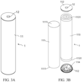
- the battery cell 1 may be, for example, a lithium-ion secondary battery, a lithium-ion primary battery, a lithium-sulfur battery, a sodium-ion battery, a magnesium-ion battery, or the like.
- the basic structures of the battery 100 and the battery cell 1 have been described. The following will describe the structures related to the sampling function in the battery 100.
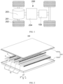
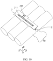
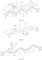
- a plurality of battery units 10 are arranged side by side along a first direction x, where each battery unit 10 includes at least two battery cells 1 arranged along a second direction y, the battery cell 1 includes a body portion 11, a gap is formed between the body portions 11 of at least one pair of adjacent battery cells 1 in the battery unit 10, at least one battery cell 1 in the adjacent battery cells 1 includes an electrode terminal 12 protruding from the body portion 11 along the second direction y, and the electrode terminal 12 is located in the gap and configured to be electrically connected to the other battery cell 1; where the second direction y is perpendicular to the first direction x.
- the sampling member 2 is electrically connected to the electrode terminal 12 of only one battery unit 10, only voltage of the battery cells 1 in one battery unit 10 can be collected. If one sampling member 2 is electrically connected to the electrode terminals 12 of a plurality of battery units 10 simultaneously, the plurality of battery units 10 can be connected in parallel through the sampling member 2, thereby implementing the series-parallel connection of a plurality of battery cells 1 in the battery 100.
- the electrical signal obtained by the sampling member 2 is the potential at the electrode terminal 12 connected to the sampling member 2.
- the voltages at two ends of one or more battery cells 1 can be calculated by obtaining the potentials of different electrode terminals 12.
- the sampling member 2 can be made of a conductive material such as metal.
- the second end of the lead-out portion 22 is led out from between the adjacent battery units 10, which can prevent occupation of extra space, increase the extension length of the second end of the lead-out portion 22, facilitate the electrical connection with the signal output component, and improve the reliability of the electrical connection.
- This allows for accurate collection of the electrical signals of the battery cells 1 and reliable monitoring of the battery cells 1 to discover abnormal situations, so as to facilitate timely control and handling, and improve the operating reliability of the battery 100.
- the welding area can be increased, so as to prevent virtual contact or disconnection of the welding point caused by long-term vibration or impact, thus improving the welding reliability.
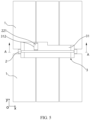
- the lead-out portion 22 does not extend beyond an outer side surface of the battery cell 1 in a third direction z, where the third direction z is perpendicular to the first direction x and the second direction y.
- the second end of the lead-out portion 22 extends in a gap between adjacent battery cells 1 in the first direction x.
- This embodiment can make the sampling member 2 not extend beyond the outer side surface of the battery cell 1 in the third direction z on the basis of increasing the extension length of the second end of the lead-out portion 22, so that arrangement of the adjacent battery cells 1 is not affected. This can minimize the size occupied by a sampling function related structure in the third direction z, thus improving the energy density of the battery 100.
- the second end of the lead-out portion 22 extends along a direction leaving the electrode terminal 12.
- the second end of the lead-out portion 22 extends in the second direction y, that is, parallel to the side wall of the body portion 11, which is convenient for increasing the extension length of the second end of the lead-out portion 22, increasing the size of the lead-out portion 22 along the first direction x, and preventing the second end of the lead-out portion 22 from affecting the side wall of the body portion 11.
- the first end of the lead-out portion 22 is close to the side end of the sampling portion 21 in the second direction y, and in the second direction y, the second end of the lead-out portion 22 extends along a direction leaving the sampling portion 21.
- the first end of the lead-out portion 22 is connected to one end of the sampling portion 21 in the second direction y, so that an operation space can be reserved for the connection between the sampling portion 21 and the electrode terminal 12.
- the second end of the lead-out portion 22 extends along a direction leaving the sampling portion 21, so that an extension direction of the second end of the lead-out portion 22 is independent of the operation region where the sampling portion 21 and the electrode terminal 12 are connected. This facilitates the connection between the second end of the lead-out portion 22 and the signal output component, as well as the connection between the sampling portion 21 and the electrode terminal 12, thus facilitating assembly and improving assembly performance.
- such design is also convenient for forming the sampling member 2 by cutting and bending the whole thin plate, with no need to connect the sampling portion 21 and the lead-out portion 22 additionally, thus reducing the manufacturing difficulty of the sampling member 2.
- the first end of the lead-out portion 22 is connected to a position of the sampling portion 21 in a center of the battery cell 1 along the first direction x, and the second end of the lead-out portion 22 extends to a position between the adjacent battery units 10 along the first direction x.
- the lead-out portion 22 may include a connecting section 223 and an extension section 222, where a first end of the connecting section 223 is connected to the sampling portion 21 and in the third direction z, extends in a direction leaving the sampling portion 21, the first end of the connecting section 223 serves as the first end of the lead-out portion 22, and an end of the extension section 222 is connected to a second end of the connecting section 223 and extends in the first direction x.
- An L-shaped structure is formed between the connecting section 223 and the extension section 222, which helps improve the rigidity of the lead-out portion 22, preventing the lead-out portion 22 from being deformed after assembly and mounting.
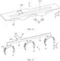
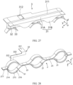
- the sampling member 2 includes a plurality of sampling portions 21 spaced apart along the first direction x, and the adjacent sampling portions 21 are connected to each other.
- the whole sampling member 2 is made of a conductive material, and the adjacent sampling portions 21 are electrically connected, thus implementing parallel connection of a plurality of battery cells 1 arranged side by side in a plurality of battery units 10.
- the sampling member 2 may further include a connecting portion 23, and the connecting portion 23 is connected between the adjacent sampling portions 21 to implement electrical connection between the adjacent sampling portions 21.
- the sampling member 2 may simultaneously collect electrical signals from the plurality of battery cells 1 arranged in the first direction x, and the electrode terminals 12 of the plurality of battery cells 1 that are electrically connected to a plurality of sampling portions 21 of one sampling member 2 have an equal potential.
- the electrode terminals 12 of the plurality of battery cells 1 that are electrically connected to a plurality of sampling portions 21 of one sampling member 2 can be designed to have an equal potential, thus achieving voltage balance of the battery cells 1 and improving consistency of detection parameters of the plurality of battery cells 1.
- the plurality of sampling portions 21 share one lead-out portion 22.
- the plurality of sampling portions 21 are electrically connected, and only one lead-out portion 22 is needed to implement lead-out of electrical signals, thus simplifying the structure and reducing the materials used for the sampling member 2.
- most of the lead-out portion 22 can be integrally fastened in the mounting part 3 by injection molding and encapsulation, and the second end of the lead-out portion 22 does not need to be fastened to the mounting part 3, so there is no need to correspondingly arrange one lead-out portion 22 for each sampling portion 21, and only one lead-out portion 22 is needed for one sampling member 2.
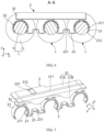
- the sampling portion 21 is of a partially annular structure, and the two ends of the connecting portion 23 are connected to the respective adjacent end portions of the adjacent sampling portions 21.
- the connecting portions 23 between each pair of adjacent sampling portions 21 are independent of each other.
- the sampling portion 21 and the connecting portion 23 can be integrally formed by bending a strip-shaped thin plate structure.
- the first end of the lead-out portion 22 can be connected to the sampling portion 21, for example, disposed at the end portion of the sampling portion 21 in the second direction y.
- the first end of the lead-out portion 22 may be connected to the connecting portion 23, for example, disposed at the end portion of the connecting portion 23 in the second direction y.
- the partially annular structured sampling portion 21 is elastic, and the two ends of the connecting portion 23 are connected to the respective adjacent end portions of adjacent sampling portions 21, so that when the battery 100 is subjected to vibration or impact, the vibration or impact can be absorbed through the deformation of the connecting portion 23 to prevent the adjacent sampling portions 21 from being disconnected, thus improving the sampling reliability of the battery cells 1.
- the connecting portion 23 is provided with a deformable section 231 configured to allow dislocation of the adjacent sampling portions 21.
- the deformable section can be made of an elastic material, or part of the length section of the connecting portion 23 can be integrally arched up to form a deformable structure, for example, the arched shape may be C-shaped, rectangular, triangular, wavy, zigzag, or of other shapes.
- the vibration or impact when the battery 100 is subjected to vibration or impact, the vibration or impact can be absorbed through the deformation of the deformable section 231, allowing for a small amount of dislocation of the adjacent sampling portions 21, preventing the adjacent sampling portions 21 from being disconnected after long-term operation, and improving the sampling reliability of the battery cells 1.
- the sampling member 2 further includes a connecting portion 23, where the connecting portion 23 is connected between adjacent sampling portions 21, the first end of the lead-out portion 22 is connected at a position of the connecting portion 23 between adjacent battery units 10, and the second end of the lead-out portion 22 extends in the third direction z, the third direction z being perpendicular to the first direction x and the second direction y.
- the first end of the lead-out portion 22 is connected to the connecting portion 23, which is equivalent to the first end of the lead-out portion 22 being connected to the sampling portion 21 through the connecting portion 23.
- adjacent sampling portions 21 are electrically connected through the connecting portion 23, so that the plurality of sampling portions 21 can be connected into a whole.
- the first end of the lead-out portion 22 is directly connected to the position of the connecting portion 23 between the battery units 10, so that the second end of the lead-out portion 22 can reach the position between the adjacent battery units 10 when the second end of the lead-out portion 22 directly extends in the third direction z, thus simplifying the structure of the lead-out portion 22.
- two ends of the connecting portion 23 are respectively connected to the positions of adjacent sampling portions 21 close to the lead-out portion 22 in the third direction z.
- the connecting portions 23 between each pair of adjacent sampling portions 21 can be connected into a whole, for example, the connecting portion 23 includes a strip structure extending between the sampling portions 21 at two ends in the first direction x.
- the connecting portion 23 may be disposed at a side end of the sampling portion 21 in the second direction y and extend in a plane perpendicular to the second direction y, so as to prevent the connecting portion 23 from occupying the operation space for connecting the sampling portion 21 and the electrode terminal 12.
- the first end of the lead-out portion 22 can be connected to the connecting portion 23.
- This embodiment is beneficial to ensure the relative positions of the sampling portions 21, so that the sampling portions 21 are aligned with the electrode terminals 12 for connection, preventing the electrode terminals 12 from being subjected to lateral pulling force during mounting of the sampling portions 21.
- the connecting portion 23 can be encapsulated and molded in the mounting part 3 to implement more reliable fixation between the sampling member 2 and the mounting part 3, so as to reduce the acting force on the lead-out portion 22.
- this structure can also reduce the overall length of the lead-out portion 22, which is beneficial to improve the rigidity of the lead-out portion 22 and prevent the lead-out portion 22 from being deformed.
- the second portion 32 may be of a rectangular structure, and the second portion 32 is connected to a side surface of the first portion 31 close to the battery cell 1, and is located in the gap in the second direction y.
- the lead-out portion 22 or the connecting portion 23 may be fastened in the second portion 32 by injection molding and encapsulation to improve the insulation performance.
- the mounting plate 31A and the second portion 32 form a T-shaped structure, and the positioning portion 31B can be located on one or two sides of the second portion 32 in the second direction y.
- the lead-out portion 22 further includes a bending section 221, and the bending section 221 extends in a plane perpendicular to the third direction z, so as to apply pressure along the third direction z to connect the signal output component to the bending section 221, for example, by welding or riveting.
- the bending section 221 is connected to a second end of the extension section 222. As shown in FIG. 9 , the bending section 221 is connected to a second end of the extension section 222.
- the bending section 221 is connected to the connecting portion 23 through the connecting section 223.
- the bending section 221 may be of a rectangular structure, and correspondingly, the accommodating groove 312 may also be of a rectangular structure.
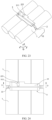
- the mounting part 3 is provided to facilitate the connection of the sampling member 2 and position the sampling member 2 relative to the battery cell 1, thus ensuring the position accuracy of the mounted sampling member 2 and preventing the sampling member 2 from shaking.
- the accommodating groove 312 is provided on the mounting part 3 to accommodate the second end of the lead-out portion 22, which can protect the second end of the lead-out portion 22, prevent the second end of the lead-out portion 22 from being deformed due to collision during assembly, and ensure the insulation of the second end of the lead-out portion 22.
- the mounting part 3 is provided with an opening 313, the opening 313 is disposed opposite the electrode terminal 12 in the first direction x, and the opening 313 is configured to form a channel for connecting the sampling portion 21 and the electrode terminal 12.
- the opening 313 is provided on the mounting part 3 to provide an operation space for connecting the sampling portion 21 and the electrode terminal 12, which facilitates assembly of the sampling member 2 and improves the connection reliability between the sampling portion 21 and the electrode terminal 12.
- the accommodating groove 312 is located on one side of the opening 313 in the second direction y, so that the operation space for connecting the sampling portion 21 and the electrode terminal 12 is spatially independent of the second end of the lead-out portion 22, thus facilitating assembly and improving assembly performance.
- the second end of the lead-out portion 22 can be supported when pressure is applied in the third direction z to connect the signal output component and the second end of the lead-out portion 22, so as to prevent the mounting part 3 from being crashed, thus improving the connection reliability between the signal output component and the second end of the lead-out portion 22 and facilitating the application of pressure during assembly.
- the sampling portion 21 is connected to the circumferential side wall of the electrode terminal 12, which can improve the reliability and stability of the connection and keep the contact area between the sampling portion 21 and the electrode terminal 12 stable, thus improving the accuracy of the sampling results.
- the size of the sampling portion 21 in the second direction y can be increased, improving the connection stability between the sampling portion 21 and the electrode terminal 12.
- the sampling portion 21 may be connected to only one electrode terminal 12 to avoid the welding position.
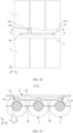
- the sampling portion 21 is of a partially annular structure, and the sampling portion 21 is in interference fit with the electrode terminal 12.
- the sampling portion 21 can be elastic. During assembly, the sampling portion 21 can be snap-fitted onto the outer wall of the electrode terminal 12 by applying a pressing force to the sampling member 2 in the third direction z. To implement snap-fitting, the sampling portion 21 needs to be more than half a ring. The interference fit allows for a tight fit between the sampling portion 21 and the electrode terminal 12, preventing relative dislocation.
- the mounting manner of this embodiment makes the sampling member 2 easy to assemble and mount, and facilitates automation, thus lowering requirements for the assembly device, improving assembly efficiency, and reducing costs.
- the sampling portion 21 is of a partially annular structure and is laser-welded to the electrode terminal 12.
- the sampling portion 21 can be designed to be no more than half a ring.
- the sampling portion 21 may be designed to be more than half a ring, so as to snap-fit the sampling portion 21 with the electrode terminal 12 before welding.
- a protruding portion 211 is provided on an inner wall of the sampling portion 21, and the protruding portion 211 is in contact with the circumferential side wall of the electrode terminal 12.
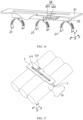
- the sampling member 2 further includes a lead-out portion 22, a first end of the lead-out portion 22 is connected to a side end of one of the sampling portions 21 in the second direction y, for example, connected to the outermost sampling portion 21, and a second end of the lead-out portion 22 is led out from between the body portions 11 of two adjacent battery cells 1 along the first direction x.
- a surface of the mounting part 3 far away from the battery cell 1 in the third direction z is provided with a groove 311.
- the groove 311 extends in the first direction x, and the bottom of the groove 311 is provided with a plurality of openings 313 spaced apart in the first direction x.
- the plurality of openings 313 are opposite the electrode terminals 12 of the plurality of battery cells 1 in the first direction x.
- the opening 313 forms a channel for laser-welding the sampling portion 21 and the electrode terminal 12.
- the sampling portion 21 includes a first snap ring 214 and a second snap ring 215, where the first snap ring 214 and the second snap ring 215 together surround the circumferential side wall of the electrode terminal 12.
- Both the first snap ring 214 and the second snap ring 215 may be of a semi-ring structure.
- the adjacent end portions of the adjacent first snap rings 214 are connected through the connecting portion 23, and the adjacent end portions of the first snap rings 214 are also connected through the connecting portion 23.
- This disclosure provides a manufacturing method of the battery 100.
- the manufacturing method includes the following steps.
- the second end of the lead-out portion 22 is led out from between the adjacent battery units 10, which can prevent occupation of extra space, increase the extension length of the second end of the lead-out portion 22, facilitate the electrical connection with the signal output component, and improve the reliability of the electrical connection.
- This allows for accurate collection of the electrical signals of the battery cells 1 and reliable monitoring of the battery cells 1 to discover abnormal situations, so as to facilitate timely control and handling, and improve the operating reliability of the battery 100.
- the welding area can be increased, so as to prevent virtual contact or disconnection of the welding point caused by long-term vibration or impact, thus improving the welding reliability.
Landscapes
- Chemical & Material Sciences (AREA)
- Chemical Kinetics & Catalysis (AREA)
- Electrochemistry (AREA)
- General Chemical & Material Sciences (AREA)
- Engineering & Computer Science (AREA)
- Manufacturing & Machinery (AREA)
- Connection Of Batteries Or Terminals (AREA)
Applications Claiming Priority (1)
| Application Number | Priority Date | Filing Date | Title |
|---|---|---|---|
| PCT/CN2021/121141 WO2023050022A1 (zh) | 2021-09-28 | 2021-09-28 | 电池及其制造方法和制造装置、用电装置 |
Publications (2)
| Publication Number | Publication Date |
|---|---|
| EP4395000A1 true EP4395000A1 (de) | 2024-07-03 |
| EP4395000A4 EP4395000A4 (de) | 2024-10-16 |
Family
ID=85780931
Family Applications (1)
| Application Number | Title | Priority Date | Filing Date |
|---|---|---|---|
| EP21958621.1A Pending EP4395000A4 (de) | 2021-09-28 | 2021-09-28 | Batterie, verfahren und vorrichtung zur herstellung davon und elektrische vorrichtung |
Country Status (4)
| Country | Link |
|---|---|
| US (1) | US20240243447A1 (de) |
| EP (1) | EP4395000A4 (de) |
| CN (1) | CN116670907A (de) |
| WO (1) | WO2023050022A1 (de) |
Families Citing this family (2)
| Publication number | Priority date | Publication date | Assignee | Title |
|---|---|---|---|---|
| EP4258443A4 (de) * | 2021-10-18 | 2024-10-30 | Contemporary Amperex Technology (Hong Kong) Limited | Abtastanordnung, herstellungsverfahren dafür, batterie und elektrische vorrichtung |
| US20250260078A1 (en) * | 2024-02-12 | 2025-08-14 | Rivian Ip Holdings, Llc | Interwoven voltage sense harness of a battery |
Family Cites Families (9)
| Publication number | Priority date | Publication date | Assignee | Title |
|---|---|---|---|---|
| JP4767009B2 (ja) * | 2005-12-14 | 2011-09-07 | 日立ビークルエナジー株式会社 | 組電池 |
| US8647766B2 (en) * | 2010-06-22 | 2014-02-11 | Ford Global Technologies, Llc | Voltage detection in a battery |
| JP5776935B2 (ja) * | 2011-09-06 | 2015-09-09 | 株式会社オートネットワーク技術研究所 | 電池配線モジュール及び電池モジュール温度調整システム |
| CN103715473B (zh) * | 2012-09-29 | 2016-01-20 | 北京有色金属研究总院 | 一种动力电池热管理系统 |
| WO2015149275A1 (zh) * | 2014-04-01 | 2015-10-08 | 深圳市智轮电动车驱动技术有限公司 | 动力电池及其电芯状态采集装置 |
| KR101805546B1 (ko) * | 2016-03-08 | 2017-12-07 | 삼성에스디아이 주식회사 | 절곡부를 갖춘 연결 탭을 포함하는 전지 팩 |
| CN206742445U (zh) * | 2017-05-18 | 2017-12-12 | 东莞市沃泰通新能源有限公司 | 一种电池模组温度检测结构 |
| CN208939116U (zh) * | 2018-11-30 | 2019-06-04 | 福州大学 | 一种车用动力电池组双向均衡散热装置 |
| CN113325322B (zh) * | 2021-05-25 | 2025-11-28 | 深圳迈巨微电子科技有限责任公司 | 信号处理装置、电池管理器件及电池管理系统 |
-
2021
- 2021-09-28 EP EP21958621.1A patent/EP4395000A4/de active Pending
- 2021-09-28 CN CN202180088199.6A patent/CN116670907A/zh active Pending
- 2021-09-28 WO PCT/CN2021/121141 patent/WO2023050022A1/zh not_active Ceased
-
2024
- 2024-03-27 US US18/618,908 patent/US20240243447A1/en active Pending
Also Published As
| Publication number | Publication date |
|---|---|
| EP4395000A4 (de) | 2024-10-16 |
| US20240243447A1 (en) | 2024-07-18 |
| WO2023050022A1 (zh) | 2023-04-06 |
| CN116670907A (zh) | 2023-08-29 |
Similar Documents
| Publication | Publication Date | Title |
|---|---|---|
| US20250105410A1 (en) | End cover assembly, battery cell, battery, and electric apparatus | |
| EP4300702A1 (de) | Batteriezelle, batterie, elektrische vorrichtung sowie verfahren und vorrichtung zur herstellung einer batteriezelle | |
| CN115458880B (zh) | 端盖组件、储能装置以及用电设备 | |
| EP4152428B1 (de) | Batteriezelle, batterie und elektrische vorrichtung | |
| US20240106084A1 (en) | Battery cell, battery, power consumption device, and method and device for producing battery cell | |
| US20240243447A1 (en) | Battery, manufacturing method and manufacturing apparatus thereof, and electric apparatus | |
| US20220407190A1 (en) | Battery, device, and method and apparatus for manufacturing battery | |
| US20240283059A1 (en) | Battery cell, method and system for manufacturing battery cell, battery, and electrical device | |
| EP4668467A1 (de) | Batteriezelle, batterie und elektrische vorrichtung | |
| EP4120463A1 (de) | Batterie, leistungsvorrichtung und batterieherstellungsverfahren und -vorrichtung | |
| US20240396128A1 (en) | Battery cell, battery, and electric device | |
| US20250149743A1 (en) | Battery cell, battery and electrical apparatus | |
| US20240304959A1 (en) | End cover assembly, battery cell, battery, and electric device | |
| CN116830376A (zh) | 电极组件及制造方法和装置、电池单体、电池、用电装置 | |
| EP4421975A1 (de) | Batteriezelle, batterie und elektrische vorrichtung | |
| KR102812545B1 (ko) | 전지, 전기 장치, 전지의 제조 방법 및 제조 설비 | |
| EP4618305A1 (de) | Batteriezelle, batterie und elektrische vorrichtung | |
| US20240234988A1 (en) | Battery cell and manufacturing method and manufacturing system therefor, battery and electrical device | |
| US12025677B2 (en) | Battery, electric apparatus, and method for preparing battery | |
| EP4583277A1 (de) | Batterie und elektrische vorrichtung | |
| EP4465419A1 (de) | Batterie und elektrische vorrichtung | |
| US12224456B2 (en) | Connection component, battery cell, battery and electrical device | |
| EP4354556A1 (de) | Stromsammelkomponente, batteriezelle, batterie und elektrische vorrichtung | |
| EP4693644A1 (de) | Batteriezelle, batterie und elektrische vorrichtung | |
| US20240145876A1 (en) | Battery cell, manufacturing method and manufacturing device thereof, battery, and electric apparatus |
Legal Events
| Date | Code | Title | Description |
|---|---|---|---|
| STAA | Information on the status of an ep patent application or granted ep patent |
Free format text: STATUS: THE INTERNATIONAL PUBLICATION HAS BEEN MADE |
|
| PUAI | Public reference made under article 153(3) epc to a published international application that has entered the european phase |
Free format text: ORIGINAL CODE: 0009012 |
|
| STAA | Information on the status of an ep patent application or granted ep patent |
Free format text: STATUS: REQUEST FOR EXAMINATION WAS MADE |
|
| 17P | Request for examination filed |
Effective date: 20240328 |
|
| AK | Designated contracting states |
Kind code of ref document: A1 Designated state(s): AL AT BE BG CH CY CZ DE DK EE ES FI FR GB GR HR HU IE IS IT LI LT LU LV MC MK MT NL NO PL PT RO RS SE SI SK SM TR |
|
| RAP1 | Party data changed (applicant data changed or rights of an application transferred) |
Owner name: CONTEMPORARY AMPEREX TECHNOLOGY(HONG KONG) LIMITED |
|
| A4 | Supplementary search report drawn up and despatched |
Effective date: 20240912 |
|
| RIC1 | Information provided on ipc code assigned before grant |
Ipc: H01M 50/502 20210101ALI20240906BHEP Ipc: H01M 10/48 20060101AFI20240906BHEP |
|
| DAV | Request for validation of the european patent (deleted) | ||
| DAX | Request for extension of the european patent (deleted) | ||
| GRAP | Despatch of communication of intention to grant a patent |
Free format text: ORIGINAL CODE: EPIDOSNIGR1 |
|
| STAA | Information on the status of an ep patent application or granted ep patent |
Free format text: STATUS: GRANT OF PATENT IS INTENDED |