EP4439232A1 - Server heat dissipation control device and server heat dissipation control method - Google Patents
Server heat dissipation control device and server heat dissipation control method Download PDFInfo
- Publication number
- EP4439232A1 EP4439232A1 EP22939888.8A EP22939888A EP4439232A1 EP 4439232 A1 EP4439232 A1 EP 4439232A1 EP 22939888 A EP22939888 A EP 22939888A EP 4439232 A1 EP4439232 A1 EP 4439232A1
- Authority
- EP
- European Patent Office
- Prior art keywords
- heat dissipation
- box body
- server
- driving member
- flow guide
- Prior art date
- Legal status (The legal status is an assumption and is not a legal conclusion. Google has not performed a legal analysis and makes no representation as to the accuracy of the status listed.)
- Granted
Links
Images


Classifications
-
- G—PHYSICS
- G06—COMPUTING OR CALCULATING; COUNTING
- G06F—ELECTRIC DIGITAL DATA PROCESSING
- G06F1/00—Details not covered by groups G06F3/00 - G06F13/00 and G06F21/00
- G06F1/16—Constructional details or arrangements
- G06F1/18—Packaging or power distribution
- G06F1/181—Enclosures
-
- H—ELECTRICITY
- H05—ELECTRIC TECHNIQUES NOT OTHERWISE PROVIDED FOR
- H05K—PRINTED CIRCUITS; CASINGS OR CONSTRUCTIONAL DETAILS OF ELECTRIC APPARATUS; MANUFACTURE OF ASSEMBLAGES OF ELECTRICAL COMPONENTS
- H05K7/00—Constructional details common to different types of electric apparatus
- H05K7/20—Modifications to facilitate cooling, ventilating, or heating
- H05K7/2029—Modifications to facilitate cooling, ventilating, or heating using a liquid coolant with phase change in electronic enclosures
- H05K7/20318—Condensers
-
- G—PHYSICS
- G06—COMPUTING OR CALCULATING; COUNTING
- G06F—ELECTRIC DIGITAL DATA PROCESSING
- G06F1/00—Details not covered by groups G06F3/00 - G06F13/00 and G06F21/00
- G06F1/16—Constructional details or arrangements
- G06F1/20—Cooling means
-
- H—ELECTRICITY
- H05—ELECTRIC TECHNIQUES NOT OTHERWISE PROVIDED FOR
- H05K—PRINTED CIRCUITS; CASINGS OR CONSTRUCTIONAL DETAILS OF ELECTRIC APPARATUS; MANUFACTURE OF ASSEMBLAGES OF ELECTRICAL COMPONENTS
- H05K7/00—Constructional details common to different types of electric apparatus
- H05K7/20—Modifications to facilitate cooling, ventilating, or heating
- H05K7/2029—Modifications to facilitate cooling, ventilating, or heating using a liquid coolant with phase change in electronic enclosures
- H05K7/203—Modifications to facilitate cooling, ventilating, or heating using a liquid coolant with phase change in electronic enclosures by immersion
-
- H—ELECTRICITY
- H05—ELECTRIC TECHNIQUES NOT OTHERWISE PROVIDED FOR
- H05K—PRINTED CIRCUITS; CASINGS OR CONSTRUCTIONAL DETAILS OF ELECTRIC APPARATUS; MANUFACTURE OF ASSEMBLAGES OF ELECTRICAL COMPONENTS
- H05K7/00—Constructional details common to different types of electric apparatus
- H05K7/20—Modifications to facilitate cooling, ventilating, or heating
- H05K7/2029—Modifications to facilitate cooling, ventilating, or heating using a liquid coolant with phase change in electronic enclosures
- H05K7/20327—Accessories for moving fluid, for connecting fluid conduits, for distributing fluid or for preventing leakage, e.g. pumps, tanks or manifolds
-
- H—ELECTRICITY
- H05—ELECTRIC TECHNIQUES NOT OTHERWISE PROVIDED FOR
- H05K—PRINTED CIRCUITS; CASINGS OR CONSTRUCTIONAL DETAILS OF ELECTRIC APPARATUS; MANUFACTURE OF ASSEMBLAGES OF ELECTRICAL COMPONENTS
- H05K7/00—Constructional details common to different types of electric apparatus
- H05K7/20—Modifications to facilitate cooling, ventilating, or heating
- H05K7/20709—Modifications to facilitate cooling, ventilating, or heating for server racks or cabinets; for data centers, e.g. 19-inch computer racks
- H05K7/208—Liquid cooling with phase change
- H05K7/20818—Liquid cooling with phase change within cabinets for removing heat from server blades
-
- H—ELECTRICITY
- H05—ELECTRIC TECHNIQUES NOT OTHERWISE PROVIDED FOR
- H05K—PRINTED CIRCUITS; CASINGS OR CONSTRUCTIONAL DETAILS OF ELECTRIC APPARATUS; MANUFACTURE OF ASSEMBLAGES OF ELECTRICAL COMPONENTS
- H05K7/00—Constructional details common to different types of electric apparatus
- H05K7/20—Modifications to facilitate cooling, ventilating, or heating
- H05K7/20709—Modifications to facilitate cooling, ventilating, or heating for server racks or cabinets; for data centers, e.g. 19-inch computer racks
- H05K7/20836—Thermal management, e.g. server temperature control
-
- G—PHYSICS
- G06—COMPUTING OR CALCULATING; COUNTING
- G06F—ELECTRIC DIGITAL DATA PROCESSING
- G06F2200/00—Indexing scheme relating to G06F1/04 - G06F1/32
- G06F2200/20—Indexing scheme relating to G06F1/20
- G06F2200/201—Cooling arrangements using cooling fluid
-
- G—PHYSICS
- G06—COMPUTING OR CALCULATING; COUNTING
- G06F—ELECTRIC DIGITAL DATA PROCESSING
- G06F2200/00—Indexing scheme relating to G06F1/04 - G06F1/32
- G06F2200/20—Indexing scheme relating to G06F1/20
- G06F2200/202—Air convective hinge
-
- Y—GENERAL TAGGING OF NEW TECHNOLOGICAL DEVELOPMENTS; GENERAL TAGGING OF CROSS-SECTIONAL TECHNOLOGIES SPANNING OVER SEVERAL SECTIONS OF THE IPC; TECHNICAL SUBJECTS COVERED BY FORMER USPC CROSS-REFERENCE ART COLLECTIONS [XRACs] AND DIGESTS
- Y02—TECHNOLOGIES OR APPLICATIONS FOR MITIGATION OR ADAPTATION AGAINST CLIMATE CHANGE
- Y02D—CLIMATE CHANGE MITIGATION TECHNOLOGIES IN INFORMATION AND COMMUNICATION TECHNOLOGIES [ICT], I.E. INFORMATION AND COMMUNICATION TECHNOLOGIES AIMING AT THE REDUCTION OF THEIR OWN ENERGY USE
- Y02D10/00—Energy efficient computing, e.g. low power processors, power management or thermal management
Definitions
- the present invention relates to the technical field of servers, and in particular, to a control device for a heat dissipation of a server.
- the present invention further relates to a method for controlling heat dissipation of a server, which is applied to the control device for the heat dissipation of the server.
- a two-phase immersion liquid-cooled system uses a latent heat of vaporization phase change of a heat dissipation working medium to carry away heat quickly, which undoubtedly has a highest cooling efficiency and a highest heat dissipation density.
- a thermally-conductive engineering liquid such as a fluorinated liquid
- the heat dissipation working medium needs to be arranged in an enclosed box body, and a server in the enclosed box body is immersed in the engineering liquid to achieve heat dissipation.
- An object of some embodiments of the present invention is to provide a control device for the heat dissipation of a server and a method for controlling heat dissipation of a server which is applied to the control device for the heat dissipation of the server, which are able to increase the heat dissipation efficiency, and solve the problems of loss due to leakage of a fluorinated liquid and potential safety risks when the cover of a box body is opened for maintenance of the server.
- some embodiments of the present invention provide a control device for a heat dissipation of a server, configured for heat dissipation of the server and comprising:
- the flow guide driving member is arranged at a side close to an inlet of the condensing coil.
- an accommodating space is formed between the condensing coil and the box body, the flow guide driving member is arranged in the accommodating space, and the condensing coil covers the flow guide driving member in an arrangement direction of the server.
- the gas-liquid separator comprises a first baffle plate and a second baffle plate; the first baffle plate is connected with the flow guide driving member, and the second baffle plate is connected with the first baffle plate and is arranged at a preset included angle relative to the first baffle plate.
- the device further comprises a ventilation valve, wherein the ventilation valve is arranged on the cover plate, and an air separated by the gas-liquid separator is discharged out of the box body through the ventilation valve.
- the device further comprises:
- the device further comprises a pressure regulating valve, wherein the pressure regulating valve is arranged on the cover plate and is connected to the control assembly, and the pressure regulating valve is configured to regulate the pressure inside the box body.
- Some embodiments of the present invention further provide a method for controlling heat dissipation of a server, applied to the control device for the heat dissipation of a server of any one above and comprising:
- a control device for a heat dissipation of a server provided in embodiments of the present invention is configured for heat dissipation of the server.
- the device specifically includes a box body, a cover plate, a heat dissipation working medium and a condensing module, wherein the server is arranged in the box body, the cover plate is connected with the box body, and the cover plate is configured to close the box body so as to improve an enclosed space for a heat dissipation circulation of the server; the heat dissipation working medium is arranged in the box body, and the server is immersed in the heat dissipation working medium, for heat dissipation of the server; and the condensing module is arranged in the box body.
- the condensing module specifically includes a condensing coil, a flow guide driving member and a gas-liquid separator, wherein the condensing coil is arranged in the box body, the condensing coil is configured to assist phase change of the heat dissipation working medium, so as to achieve heat dissipation circulation.
- the phase change refers to a process in which the heat dissipation working medium vaporized into a gas state is condensed into a liquid after releasing heat on the condensing coil; the heat dissipation working medium condensed into the liquid state falls back into the box body under an action of gravity, thereby achieving the heat dissipation circulation; and the flow guide driving member is arranged towards the condensing coil, and the flow guide driving member is configured to provide a driving force to control the heat dissipation working medium in a steam/gas state to flow towards the condensing coil; and the gas-liquid separator is arranged at an outlet of the flow guide driving member, and the gas-liquid separator is configured to separate an air and a droplet-shaped heat dissipation working medium.
- the method for controlling heat dissipation of a server is applied to the control device for the heat dissipation of the server, and includes: it is determined whether the cover plate on the box body is closed; if the cover plate is closed, it is determined whether the pressure in the box body is the first normal value; if it is determined that the pressure in the box body is not the first normal value, the flow guide driving member is controlled to operate; after the heat dissipation working medium flows towards a condensing coil and is condensed by the condensing coil, the air and droplet-shaped heat dissipation working medium flow to the gas-liquid separator through the outlet of the flow guide driving member; the gas-liquid separator separates the air from the droplet-shaped heat dissipation working medium, and the air is discharged upwards out of the box body, so that the pressure in the box body is adjusted to the first normal value; and if the cover plate is opened, it is determined whether the pressure in the box body is the
- the device and method for controlling heat dissipation of a server are able to increase the condensation efficiency, thereby increasing the heat dissipation efficiency; in addition, the leakage of the fluorinated liquid when the cover of the box body is opened for maintenance of the server is able to be solved, so that not only the loss of the fluorinated liquid is able to be reduced, but also the problem of potential safety risks caused by the leakage of the fluorinated liquid is able to be solved, thereby improving the safety.
- Fig. 6 is a front view of the control device for a heat dissipation of a server as shown in Fig. 1 ;
- Fig. 7 is a schematic diagram of an overall structure of a control device for a heat dissipation of a server after a cover is opened according to embodiments of the present invention; and
- Fig. 8 is a flowchart of a method for controlling heat dissipation of a server according to embodiments of the present invention.
- the control device 1 for the heat dissipation of the server provided in embodiments of the present invention is able to increase the condensation efficiency, thereby increasing the heat dissipation efficiency; in addition, the leakage of the fluorinated liquid when a cover of the box body 10 is opened for maintenance of the server 103 is able to be solved, so that not only the loss of the fluorinated liquid is able to be reduced, but also the problem of potential safety risks caused by the leakage of the fluorinated liquid is able to be solved, thereby improving the safety.
- the flow guide driving member 1022 may specifically be configured as a cross-flow fan, an axial-flow fan, or the like. According to application scenarios of the present invention, the cross-flow fan is adopted in some embodiments of the present invention.
- control device 1 for the heat dissipation of a two-phase immersion liquid-cooled server proposed in some embodiments of the present invention, with the provision of the condensing module 102, during normal operation, a main driving force for flowing of steam is provided by a suction force of the cross-flow fan, thereby preventing the steam from directly impacting the cover plate 11 upwards and then bouncing back and reducing the local loss during steam impacting and bouncing back; moreover, in cases where the condensation zone maintains the same pressure, the pressure in the evaporation zone is able to be reduced, that is, a boiling point of the fluorinated liquid is reduced, and finally a temperature of chips inside the server 103 is reduced. If a same chip temperature is maintained, a thermal flux density of the chips is able to be increased, i.e. a high heat dissipation density is achieved.
- the arrangement manner above is able to fundamentally solve the problem of a large loss of fluorinated liquid steam when the cover of the box body 10 is opened for maintenance, and is able to also greatly increase the condensation efficiency of a condenser, achieve a high heat dissipation density, and reduce the costs of a heat dissipation apparatus per unit of power consumption.
- the flow guide driving member 1022 is arranged on a side close to an inlet of the condensing coil 1021.
- the pressure inside the box body 10 is controlled by adjusting an operating speed of the cross-flow fan, so as to achieve a balance of air pressures inside and outside the box body 10, thereby preventing the steam from leaking to the outside of the box body 10.
- the cross-flow fan is arranged at or near an inlet side of the condensing coil 1021, and as the condensation capability at this position is the strongest, a fluorinated liquid steam suctioned by the cross-flow fan is completely condensed in the condensing module 102, thereby greatly increasing the condensation efficiency.
- an accommodating space is formed between the condensing coil 1021 and a side wall of the box body 10, the flow guide driving member 1022 is arranged in the accommodating space, and the condensing coil 1021 covers the flow guide driving member 1022 in an arrangement direction of the server 103.
- the flow guide driving member 1022 is arranged between the condensing coil 1021 and the side wall of the box body 10.
- the server 103 is generally arranged vertically in the box body 10, and therefore, the condensing coil 1021 covers the flow guide driving member 1022 in a vertical direction, which is able to ensure that the condensation zone in the box body 10 is large enough and the flow guide driving member 1022 is covered by the condensation zone.
- the condensing coil 1021 is specifically a coil having an S-shaped cross section.
- the inlet of the condensing coil 1021 is connected with a first end of a condensing pipeline located outside the box body 10, the condensing pipeline is provided with refrigeration assemblies such as a pump and a compressor, and an outlet of the condensing coil 1021 is connected with a second end of the condensing pipeline located outside the box body 10; in this way, refrigeration circulation is able to be realized.
- the structure of the S-shaped coil is able to increase the condensation area, thereby greatly increasing the condensation efficiency in the box body 10.
- the condensing module 102 Taking the condensing module 102 arranged on a single side as an example, after a system is put in, the fluorinated liquid absorbs the heat generated by the server 103, is vaporized into a fluorinated liquid gas when the liquid reaches a saturation temperature, releases heat on the condensing coil 1021 and is condensed into a liquid, and falls back to the inside of the box body 10 under the action of gravity, thereby realizing heat dissipation circulation.
- the condensing module 102 may also be arranged on two sides of the server 103 according to actual requirements.
- some embodiments of the present invention realize gas-liquid separation by the gas-liquid separator 1023.
- the fluorinated liquid steam suctioned by the cross-flow fan is completely condensed on the condensing module 102, and under the driving of the cross-flow fan, small-particle droplets of the fluorinated liquid and a small amount of air enter the fan from a side of the fan close to the condensing coil 1021; then the small-particle droplets of the fluorinated liquid and the small amount of air flow out along an outlet at a bottom of the fan under a driving action of fan blades, and the outlet at the bottom of the fan is a through hole, that is, an outlet position of the cross-flow fan mainly includes the small-particle droplets of the fluorinated liquid and the small amount of air, and baffle plates with a certain angle are provided at an outlet of the cross-flow fan.
- the control device for the heat dissipation of the server further includes a ventilation valve 12; the ventilation valve 12 is arranged at a bottom of the cover plate 11, and an air separated by the gas-liquid separator 1023 is discharged out of the box body 10 through the ventilation valve 12.
- control device for the heat dissipation of the server further includes a pressure measurement assembly and a control assembly, wherein the pressure measurement assembly is arranged in the box body 10, and the pressure measurement assembly is configured to measure the pressure in the box body 10; the control assembly is connected with the pressure measurement assembly and the flow guide driving member 1022, and the control assembly is configured to control an operation of the flow guide driving member 1022 according to a pressure value measured by the pressure measurement assembly.
- the control assembly may be a PLC.
- the pressure measurement assembly may include a first pressure sensor 15 and a second pressure sensor 16; the first pressure sensor 15 is arranged between the cover plate 11 and the box body 10 or on the cover plate 11 and is configured to detect whether the cover plate 11 is in a closed state or an open state, and the second pressure sensor 16 is arranged at the bottom of the cover plate 11 and is configured to measure a pressure value in the box body 10; in addition, a liquid level meter and a temperature sensor 17 are further arranged inside the box body 10.
- a method for controlling heat dissipation of a server provided by the embodiments of the present invention is applied to the control device 1 for the heat dissipation of the server, and includes:
- the arrangement manner above is able to maintain the pressure in the box body 10 to be the normal value, thereby increasing the heat dissipation efficiency of the server 103.
- the method for controlling heat dissipation of the server specifically includes:
Landscapes
- Engineering & Computer Science (AREA)
- Physics & Mathematics (AREA)
- Theoretical Computer Science (AREA)
- Microelectronics & Electronic Packaging (AREA)
- General Engineering & Computer Science (AREA)
- Thermal Sciences (AREA)
- Human Computer Interaction (AREA)
- General Physics & Mathematics (AREA)
- Computer Hardware Design (AREA)
- Power Engineering (AREA)
- Cooling Or The Like Of Electrical Apparatus (AREA)
Abstract
Description
- The present invention claims priority to
Chinese Patent Application No. 202210462562.2, filed to the China National Intellectual Property Administration on April 29, 2022 - The present invention relates to the technical field of servers, and in particular, to a control device for a heat dissipation of a server. The present invention further relates to a method for controlling heat dissipation of a server, which is applied to the control device for the heat dissipation of the server.
- Currently, in order to meet the ever-increasing computing power requirements of data centers, the power density of a single cabinet is becoming higher and higher. Under this context, heat dissipation technologies for liquid-cooled data centers with low PUE (abbreviation for Power Usage Effectiveness, which is an index for evaluating an energy efficiency of a data center) and high heat dissipation density emerge as required.
- In a related art, a two-phase immersion liquid-cooled system uses a latent heat of vaporization phase change of a heat dissipation working medium to carry away heat quickly, which undoubtedly has a highest cooling efficiency and a highest heat dissipation density. In the two-phase immersion liquid-cooled system, a thermally-conductive engineering liquid (the heat dissipation working medium), such as a fluorinated liquid, needs to be arranged in an enclosed box body, and a server in the enclosed box body is immersed in the engineering liquid to achieve heat dissipation. However, when maintenance of the server is required, it is necessary to open a cover plate of the enclosed box body, which causes a leakage of the fluorinated liquid, leading to economic loss and safety risks caused by a large amount of leakage of the expensive fluorinated liquid.
- An object of some embodiments of the present invention is to provide a control device for the heat dissipation of a server and a method for controlling heat dissipation of a server which is applied to the control device for the heat dissipation of the server, which are able to increase the heat dissipation efficiency, and solve the problems of loss due to leakage of a fluorinated liquid and potential safety risks when the cover of a box body is opened for maintenance of the server.
- In order to achieve the object above, some embodiments of the present invention provide a control device for a heat dissipation of a server, configured for heat dissipation of the server and comprising:
- a box body;
- a cover plate, connected with the box body and configured to close the box body;
- a heat dissipation working medium, arranged in the box body and configured to immerse the server; and
- a condensing module, arranged in the box body and comprising:
- a condensing coil, arranged in the box body and configured to assist phase change of the heat dissipation working medium, so as to achieve heat dissipation circulation; and
- a flow guide driving member, arranged towards the condensing coil and configured to provide a driving force to control a gaseous heat dissipation working medium to flow towards the condensing coil, so as to prevent the gaseous heat dissipation working medium from impacting the cover plate when the cover plate is closed and prevent the gaseous heat dissipation working medium from leaking to an outside of the box body when the cover plate is opened;
- wherein the condensing module further comprises a gas-liquid separator; the gas-liquid separator is arranged at an outlet of the flow guide driving member, and the gas-liquid separator is configured to separate an air and a droplet-shaped heat dissipation working medium.
- In some embodiments, the flow guide driving member is arranged at a side close to an inlet of the condensing coil.
- In some embodiments, an accommodating space is formed between the condensing coil and the box body, the flow guide driving member is arranged in the accommodating space, and the condensing coil covers the flow guide driving member in an arrangement direction of the server.
- In some embodiments, the condensing coil is an S-shaped coil.
- In some embodiments, the gas-liquid separator comprises a first baffle plate and a second baffle plate; the first baffle plate is connected with the flow guide driving member, and the second baffle plate is connected with the first baffle plate and is arranged at a preset included angle relative to the first baffle plate.
- In some embodiments, the device further comprises a ventilation valve, wherein the ventilation valve is arranged on the cover plate, and an air separated by the gas-liquid separator is discharged out of the box body through the ventilation valve.
- In some embodiments, the device further comprises:
- a first pressure sensor, arranged between the cover plate and the box body and configured to detect a state of the cover plate;
- a second pressure sensor, arranged on the cover plate and configured to measure a pressure in the box body; and
- a control assembly, connected with the first pressure sensor, the second pressure sensor and the flow guide driving member, and configured to control an operation of the flow guide driving member according to pressure values measured by the first pressure sensor and the second pressure sensor.
- In some embodiments, the device further comprises a pressure regulating valve, wherein the pressure regulating valve is arranged on the cover plate and is connected to the control assembly, and the pressure regulating valve is configured to regulate the pressure inside the box body.
- Some embodiments of the present invention further provide a method for controlling heat dissipation of a server, applied to the control device for the heat dissipation of a server of any one above and comprising:
- it is determined whether the cover plate on the box body is closed;
- if the cover plate is closed, it is determined whether a pressure in the box body is a first normal value;
- if it is determined that the pressure in the box body (10) is not the first normal value, the flow guide driving member is controlled to operate; after the heat dissipation working medium flows towards the condensing coil and is condensed by the condensing coil, the air and droplet-shaped heat dissipation working medium flow to the gas-liquid separator through the outlet of the flow guide driving member; the gas-liquid separator separates the air from the droplet-shaped heat dissipation working medium, and the air is discharged upwards out of the box body, so that the pressure in the box body is adjusted to the first normal value; and
- if the cover plate is opened, it is determined whether the pressure in the box body is a second normal value; and
- if the pressure in the box body (10) is not the second normal value, the flow guide driving member is controlled to operate; after the heat dissipation working medium flows towards the condensing coil and is condensed by the condensing coil, the air and droplet-shaped heat dissipation working medium flow to the gas-liquid separator through the outlet of the flow guide driving member; the gas-liquid separator separates the air from the droplet-shaped heat dissipation working medium, and the air is discharged upwards out of the box body, so that the pressure in the box body is adjusted to the second normal value.
- With respect to the background, a control device for a heat dissipation of a server provided in embodiments of the present invention is configured for heat dissipation of the server. The device specifically includes a box body, a cover plate, a heat dissipation working medium and a condensing module, wherein the server is arranged in the box body, the cover plate is connected with the box body, and the cover plate is configured to close the box body so as to improve an enclosed space for a heat dissipation circulation of the server; the heat dissipation working medium is arranged in the box body, and the server is immersed in the heat dissipation working medium, for heat dissipation of the server; and the condensing module is arranged in the box body. In some embodiments, the condensing module specifically includes a condensing coil, a flow guide driving member and a gas-liquid separator, wherein the condensing coil is arranged in the box body, the condensing coil is configured to assist phase change of the heat dissipation working medium, so as to achieve heat dissipation circulation. The phase change refers to a process in which the heat dissipation working medium vaporized into a gas state is condensed into a liquid after releasing heat on the condensing coil; the heat dissipation working medium condensed into the liquid state falls back into the box body under an action of gravity, thereby achieving the heat dissipation circulation; and the flow guide driving member is arranged towards the condensing coil, and the flow guide driving member is configured to provide a driving force to control the heat dissipation working medium in a steam/gas state to flow towards the condensing coil; and the gas-liquid separator is arranged at an outlet of the flow guide driving member, and the gas-liquid separator is configured to separate an air and a droplet-shaped heat dissipation working medium. In this way, the following beneficial effects are able to be brought about:
- firstly, a gaseous heat dissipation working medium is able to be sufficiently condensed on the condensing coil, thereby greatly increasing the condensation efficiency;
- secondly, the gaseous heat dissipation working medium is able to be prevented from impacting the cover plate when the cover plate is closed; if the heat dissipation working medium impacts the cover plate and then rebounds back and flows to the condensing module, the pressure loss will be increased, which is equivalent to increasing the temperature drop of the steam and indirectly decreasing the condensation efficiency, and therefore the gaseous heat dissipation working medium is able to be prevented from impacting the cover plate, thereby further increasing the condensation efficiency;
- thirdly, the gaseous heat dissipation working medium is able to be prevented from leaking to an outside of the box body when the cover plate is opened; that is to say, a flowing direction of the heat dissipation working medium is changed by the flow guide driving member, so as to prevent the heat dissipation working medium from leaking to the outside of the box body; and
- fourthly, in the embodiments of the present invention, on a basis of providing the condensing coil and the flow guide driving member, flow guide driving of fluorinated liquid steam is achieved by the flow guide driving member, thus, a guided fluorinated liquid steam is completely condensed on the condensing coil, an outlet position of the flow guide driving member mainly comprises small-particle droplets of the fluorinated liquid and a small amount of air, and the outlet of the flow guide driving member is provided with the gas-liquid separator. Due to different densities of gas and liquid, when a mixed flow encounters an obstacle, the gas will be diverted and flow away; the liquid has a continuous forward speed due to inertia, the forward liquid is attached to the gas-liquid separator, and is gathered together downwards due to an action of gravity, and finally drops back to an inside of the box body; however, the air will be diverted and flow upward due to the small density thereof, and is discharged to the outside of the box body through a top of the box body, so that the pressure in the box body is able to be always maintained at a normal value, which facilitates to ensure the stability of the operation of the system.
- In addition, the method for controlling heat dissipation of a server provided by the embodiments of the present invention is applied to the control device for the heat dissipation of the server, and includes: it is determined whether the cover plate on the box body is closed; if the cover plate is closed, it is determined whether the pressure in the box body is the first normal value; if it is determined that the pressure in the box body is not the first normal value, the flow guide driving member is controlled to operate; after the heat dissipation working medium flows towards a condensing coil and is condensed by the condensing coil, the air and droplet-shaped heat dissipation working medium flow to the gas-liquid separator through the outlet of the flow guide driving member; the gas-liquid separator separates the air from the droplet-shaped heat dissipation working medium, and the air is discharged upwards out of the box body, so that the pressure in the box body is adjusted to the first normal value; and if the cover plate is opened, it is determined whether the pressure in the box body is the second normal value; and if the pressure in the box body is not the second normal value, the flow guide driving member is controlled to operate; after the heat dissipation working medium flows towards the condensing coil and is condensed by the condensing coil, the air and droplet-shaped heat dissipation working medium flow to the gas-liquid separator through the outlet of the flow guide driving member; the gas-liquid separator separates the air from the droplet-shaped heat dissipation working medium, and the air is discharged upwards out of the box body, so that the pressure in the box body is adjusted to the second normal value. The arrangement manner above is able to maintain the pressure in the box body to be the normal value, thereby increasing the heat dissipation efficiency of the server.
- Compared with conventional heat dissipation of the server, the device and method for controlling heat dissipation of a server provided in embodiments of the present invention are able to increase the condensation efficiency, thereby increasing the heat dissipation efficiency; in addition, the leakage of the fluorinated liquid when the cover of the box body is opened for maintenance of the server is able to be solved, so that not only the loss of the fluorinated liquid is able to be reduced, but also the problem of potential safety risks caused by the leakage of the fluorinated liquid is able to be solved, thereby improving the safety.
- In order to describe the technical solutions in the embodiments of the present invention or in the related art more clearly, hereinafter, accompanying drawings requiring to be used in the embodiments or the related art will be introduced briefly. Apparently, the accompanying drawings in the following description merely relate to embodiments of the present invention, and for a person of ordinary skill in the art, other accompanying drawings can also be obtained according to the provided accompanying drawings without involving any inventive effort.
-
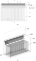
Fig. 1 is a schematic diagram of an overall structure of a control device for a heat dissipation of a server with a cover not opened according to embodiments of the present invention; -
Fig. 2 is a side view of the control device for a heat dissipation of a server as shown inFig. 1 ; -
Fig. 3 is a schematic diagram of heat dissipation of the control device for a heat dissipation of a server as shown inFig. 2 ; -
Fig. 4 is a schematic structural diagram of a condensing module inFig. 2 ; -
Fig. 5 is a top view of the control device for a heat dissipation of a server as shown inFig. 1 ; -
Fig. 6 is a front view of the control device for a heat dissipation of a server as shown inFig. 1 ; -
Fig. 7 is a schematic diagram of an overall structure of a control device for a heat dissipation of a server after a cover is opened according to embodiments of the present invention; and -
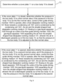
Fig. 8 is a flowchart of a method for controlling heat dissipation of a server according to embodiments of the present invention. - In the drawings:
- 1 - control device for the heat dissipation of a server;
- 10 - Box body, 11 - Cover plate, 12 - Ventilation valve, 13 - Solenoid valve, 14 - Mechanical pressure relief valve, 15 - First pressure sensor, 16 - Second pressure sensor, 17 - Liquid level meter and temperature sensor;
- 101 - Heat dissipation working medium;
- 102 - Condensing module, 1021 - Condensing coil, 1022 - Flow guide driving member, 1023 - Gas-liquid separator, 10231 - First baffle plate, 10232 - Second baffle plate;
- 103 - Server.
- Hereinafter, the technical solutions in embodiments of the present invention will be described clearly and thoroughly with reference to the accompanying drawings of the embodiments of the present invention. Obviously, the embodiments as described are only some of the embodiments of the present invention, and are not all of the embodiments of the present invention. All other embodiments obtained by a person of ordinary skill in the art on the basis of the embodiments of the present invention without any inventive effort shall all fall within the scope of protection of the present invention.
- The core of some embodiments of the present invention is to provide a control device for a heat dissipation of a server and a method for controlling heat dissipation of a server which is applied to the control device for the heat dissipation of the server, which is able to increase the heat dissipation efficiency, and solve the problems of loss due to leakage of a fluorinated liquid and potential safety risks when a cover of a box body is opened for maintenance of the server.
- To make a person skilled in the art better understand the solutions of some embodiments of the present invention, hereinafter, some embodiments of the present invention are further described in detail with reference to the accompanying drawings and the specific embodiments.
- It should be noted that, the orientation terms such as "upper end, lower end, left side and right side" described below are all defined on the basis of the drawings accompanying the description.
- Please refer to
Figs. 1-8 ,Fig. 1 is a schematic diagram of an overall structure of a control device for a heat dissipation of a server with a cover not opened according to embodiments of the present invention;Fig. 2 is a side view of the control device for a heat dissipation of a server as shown inFig. 1 ;Fig. 3 is a schematic diagram of heat dissipation of the control device for a heat dissipation of a server as shown inFig. 2 ;Fig. 4 is a schematic structural diagram of a condensation module inFig. 2 ;Fig. 5 is a top view of the control device for a heat dissipation of a server as shown inFig. 1 ;Fig. 6 is a front view of the control device for a heat dissipation of a server as shown inFig. 1 ;Fig. 7 is a schematic diagram of an overall structure of a control device for a heat dissipation of a server after a cover is opened according to embodiments of the present invention; andFig. 8 is a flowchart of a method for controlling heat dissipation of a server according to embodiments of the present invention. - The
control device 1 for the heat dissipation of the server provided in embodiments of the present invention is configured for heat dissipation of theserver 103. The device specifically includes abox body 10, acover plate 11, a heatdissipation working medium 101 and acondensing module 102, wherein theserver 103 is arranged in thebox body 10, thecover plate 11 is connected with thebox body 10, and thecover plate 11 is configured to close thebox body 10 so as to improve an enclosed space for heat dissipation circulation of theserver 103; the heatdissipation working medium 101 is arranged in thebox body 10, and theserver 103 is immersed in the heatdissipation working medium 101, and configured for heat dissipation of theserver 103; and thecondensing module 102 is arranged in thebox body 10, and thecondensing module 102 is configured to provide a condensing working condition, so that the heat dissipation working medium 101 in a gas state is condensed into a liquid after releasing heat. - In some embodiments, the heat
dissipation working medium 101 may use a fluorinated liquid. - In some embodiments, the condensing
module 102 specifically includes a condensingcoil 1021 and a flowguide driving member 1022. The condensingcoil 1021 is arranged in thebox body 10, and the condensingcoil 1021 is configured to assist phase change of the heatdissipation working medium 101, so as to achieve heat dissipation circulation. It should be noted that the phase change refers to a process in which the heatdissipation working medium 101 vaporized into a gas state is condensed into a liquid after releasing heat on the condensingcoil 1021; the heatdissipation working medium 101 condensed into the liquid state falls back into thebox body 10 under an action of gravity, thereby achieving the heat dissipation circulation; and the flowguide driving member 1022 is arranged towards the condensingcoil 1021, and the flowguide driving member 1022 is configured to provide a driving force to control the heat dissipation working medium 101 in a steam/gas state to flow towards the condensingcoil 1021. - In this way, the arrangement manner above is able to bring about many beneficial effects, specifically including: firstly, a gaseous heat
dissipation working medium 101 is able to be sufficiently condensed on the condensingcoil 1021, thereby greatly increasing the condensation efficiency; secondly, the gaseous heatdissipation working medium 101 is able to be prevented from impacting thecover plate 11 when thecover plate 11 is closed; if the heat dissipation working medium 101 impacts thecover plate 11 and then rebounds back and flows to thecondensing module 102, the pressure loss will be increased, which is equivalent to increasing the temperature drop of the steam and indirectly decreasing the condensation efficiency, and therefore the gaseous heatdissipation working medium 101 is able to be prevented from impacting thecover plate 11, thereby further increasing the condensation efficiency; and thirdly, the gaseous heatdissipation working medium 101 is able to be prevented from leaking to an outside of thebox body 10 when thecover plate 11 is opened; that is to say, a flowing direction of the heatdissipation working medium 101 is changed by the flowguide driving member 1022, so as to prevent the heat dissipation working medium 101 from leaking to the outside of thebox body 10. - Compared with conventional heat dissipation of the
server 103, thecontrol device 1 for the heat dissipation of the server provided in embodiments of the present invention is able to increase the condensation efficiency, thereby increasing the heat dissipation efficiency; in addition, the leakage of the fluorinated liquid when a cover of thebox body 10 is opened for maintenance of theserver 103 is able to be solved, so that not only the loss of the fluorinated liquid is able to be reduced, but also the problem of potential safety risks caused by the leakage of the fluorinated liquid is able to be solved, thereby improving the safety. - Certainly, according to actual needs, the flow
guide driving member 1022 may specifically be configured as a cross-flow fan, an axial-flow fan, or the like. According to application scenarios of the present invention, the cross-flow fan is adopted in some embodiments of the present invention. - It can be understood that, in cases where no cross-flow fan is provided, the driving force for gas flowing of the fluorinated liquid is derived from a pressure difference between a positive pressure of an evaporation zone and a negative pressure of a condensation zone on an upper part of the
server 103. In consideration of the leakage problem, an inside of thebox body 10 is under a normal pressure control, and the pressure difference cannot be too large; in this way, most of the steam may impact thecover plate 11 during rising inside thebox body 10, and then rebound back and flow to thecondensing module 102, which increases the pressure loss, which is equivalent to increasing a temperature drop of the steam and indirectly decreasing the condensation efficiency. When the cover of thebox body 10 needs to be opened for maintenance, this problem may cause a gas of the fluorinated liquid to flow directly to the outside of thebox body 10, thereby causing a great loss of the expensive fluorinated liquid, which not only causes an economic loss but also causes a potential safety hazard. - By the
control device 1 for the heat dissipation of a two-phase immersion liquid-cooled server proposed in some embodiments of the present invention, with the provision of thecondensing module 102, during normal operation, a main driving force for flowing of steam is provided by a suction force of the cross-flow fan, thereby preventing the steam from directly impacting thecover plate 11 upwards and then bouncing back and reducing the local loss during steam impacting and bouncing back; moreover, in cases where the condensation zone maintains the same pressure, the pressure in the evaporation zone is able to be reduced, that is, a boiling point of the fluorinated liquid is reduced, and finally a temperature of chips inside theserver 103 is reduced. If a same chip temperature is maintained, a thermal flux density of the chips is able to be increased, i.e. a high heat dissipation density is achieved. - That is to say, the arrangement manner above is able to fundamentally solve the problem of a large loss of fluorinated liquid steam when the cover of the
box body 10 is opened for maintenance, and is able to also greatly increase the condensation efficiency of a condenser, achieve a high heat dissipation density, and reduce the costs of a heat dissipation apparatus per unit of power consumption. - In some embodiments, the flow
guide driving member 1022 is arranged on a side close to an inlet of the condensingcoil 1021. - When the cover of the
box body 10 is opened for maintenance, the pressure inside thebox body 10 is controlled by adjusting an operating speed of the cross-flow fan, so as to achieve a balance of air pressures inside and outside thebox body 10, thereby preventing the steam from leaking to the outside of thebox body 10. In this case, the cross-flow fan is arranged at or near an inlet side of the condensingcoil 1021, and as the condensation capability at this position is the strongest, a fluorinated liquid steam suctioned by the cross-flow fan is completely condensed in thecondensing module 102, thereby greatly increasing the condensation efficiency. - In some embodiments, an accommodating space is formed between the condensing
coil 1021 and a side wall of thebox body 10, the flowguide driving member 1022 is arranged in the accommodating space, and the condensingcoil 1021 covers the flowguide driving member 1022 in an arrangement direction of theserver 103. - That is to say, the flow
guide driving member 1022 is arranged between the condensingcoil 1021 and the side wall of thebox body 10. Theserver 103 is generally arranged vertically in thebox body 10, and therefore, the condensingcoil 1021 covers the flowguide driving member 1022 in a vertical direction, which is able to ensure that the condensation zone in thebox body 10 is large enough and the flowguide driving member 1022 is covered by the condensation zone. - In some embodiments, the condensing
coil 1021 is specifically a coil having an S-shaped cross section. - In some embodiments, the inlet of the condensing
coil 1021 is connected with a first end of a condensing pipeline located outside thebox body 10, the condensing pipeline is provided with refrigeration assemblies such as a pump and a compressor, and an outlet of the condensingcoil 1021 is connected with a second end of the condensing pipeline located outside thebox body 10; in this way, refrigeration circulation is able to be realized. The structure of the S-shaped coil is able to increase the condensation area, thereby greatly increasing the condensation efficiency in thebox body 10. - Taking the
condensing module 102 arranged on a single side as an example, after a system is put in, the fluorinated liquid absorbs the heat generated by theserver 103, is vaporized into a fluorinated liquid gas when the liquid reaches a saturation temperature, releases heat on the condensingcoil 1021 and is condensed into a liquid, and falls back to the inside of thebox body 10 under the action of gravity, thereby realizing heat dissipation circulation. Certainly, the condensingmodule 102 may also be arranged on two sides of theserver 103 according to actual requirements. - In order to ensure the stability of the operation of the system, the condensing
module 102 further includes a gas-liquid separator 1023; the gas-liquid separator 1023 is provided at an outlet of the flowguide driving member 1022, and the gas-liquid separator 1023 is configured to separate an air and a droplet-shaped heatdissipation working medium 101. In some embodiments, the gas-liquid separator 1023 includes afirst baffle plate 10231 and asecond baffle plate 10232; thefirst baffle plate 10231 is connected with an outlet housing of the flowguide driving member 1022, and thesecond baffle plate 10232 is connected with thefirst baffle plate 10231 and is arranged at a preset included angle relative to thefirst baffle plate 10231. A range of the preset included angle is able to be adjusted according to an outlet angle of the cross-flow fan, and the range of the preset included angle is generally greater than 90°. - In this way, on a basis of providing the condensing
coil 1021 and the cross-flow fan, some embodiments of the present invention realize gas-liquid separation by the gas-liquid separator 1023. In some embodiments, the fluorinated liquid steam suctioned by the cross-flow fan is completely condensed on thecondensing module 102, and under the driving of the cross-flow fan, small-particle droplets of the fluorinated liquid and a small amount of air enter the fan from a side of the fan close to the condensingcoil 1021; then the small-particle droplets of the fluorinated liquid and the small amount of air flow out along an outlet at a bottom of the fan under a driving action of fan blades, and the outlet at the bottom of the fan is a through hole, that is, an outlet position of the cross-flow fan mainly includes the small-particle droplets of the fluorinated liquid and the small amount of air, and baffle plates with a certain angle are provided at an outlet of the cross-flow fan. By using the principle of baffle separation, i.e. due to different densities of gas and liquid, when a mixed flow encounters an obstacle, the gas will be diverted and flow away; the liquid has a continuous forward speed due to inertia, the forward liquid is attached to a blocking wall surface of the baffle plate, and is gathered together downwards due to the action of gravity, and finally drops back to the inside of thebox body 10 at a bottom of thesecond baffle plate 10232; however, the air will be diverted and flow upward due to the small density thereof, and is discharged to the outside of thebox body 10 through a top of thebox body 10, so that a pressure in thebox body 10 is able to be always maintained at a normal value, which facilitates to ensure the stability of the operation of the system. - In some embodiments, in order to facilitate air discharge, the control device for the heat dissipation of the server further includes a
ventilation valve 12; theventilation valve 12 is arranged at a bottom of thecover plate 11, and an air separated by the gas-liquid separator 1023 is discharged out of thebox body 10 through theventilation valve 12. - In some embodiments, the control device for the heat dissipation of the server further includes a pressure measurement assembly and a control assembly, wherein the pressure measurement assembly is arranged in the
box body 10, and the pressure measurement assembly is configured to measure the pressure in thebox body 10; the control assembly is connected with the pressure measurement assembly and the flowguide driving member 1022, and the control assembly is configured to control an operation of the flowguide driving member 1022 according to a pressure value measured by the pressure measurement assembly. The control assembly may be a PLC. - In some embodiments, the pressure measurement assembly may include a
first pressure sensor 15 and asecond pressure sensor 16; thefirst pressure sensor 15 is arranged between thecover plate 11 and thebox body 10 or on thecover plate 11 and is configured to detect whether thecover plate 11 is in a closed state or an open state, and thesecond pressure sensor 16 is arranged at the bottom of thecover plate 11 and is configured to measure a pressure value in thebox body 10; in addition, a liquid level meter and atemperature sensor 17 are further arranged inside thebox body 10. - In some embodiments, the control device for the heat dissipation of the server further includes a pressure regulating valve; the pressure regulating valve is arranged on the
cover plate 11 and is connected with the control assembly; the pressure regulating valve is configured to regulate the pressure inside thebox body 10. For example, asolenoid valve 13 may be arranged at the bottom of thecover plate 11, and thesolenoid valve 13 is controlled by the control assembly to achieve pressure regulation inside thebox body 10. Of course, a mechanical safety valve (a mechanical pressure relief valve 14) may also be arranged on the bottom of thecover plate 11. - In addition, a method for controlling heat dissipation of a server provided by the embodiments of the present invention is applied to the
control device 1 for the heat dissipation of the server, and includes: - S1: it is determined whether a
cover plate 11 on abox body 10 is closed; - S2: if the
cover plate 11 is closed, it is determined whether the pressure in thebox body 10 is a first normal value; if the pressure in thebox body 10 is not the first normal value, the flowguide driving member 1022 is controlled to operate; after the heat dissipation working medium 101 flows towards the condensingcoil 1021 and is condensed by the condensingcoil 1021, the air and droplet-shaped heat dissipation working medium 101 flow to the gas-liquid separator 1023 through the outlet of the flowguide driving member 1022; the gas-liquid separator 1023 separates the air from the droplet-shaped heatdissipation working medium 101, and the air is discharged upwards out of thebox body 10, so that the pressure in thebox body 10 is adjusted to the first normal value; and - S3: if the
cover plate 11 is opened, it is determined whether the pressure in thebox body 10 is a second normal value; and if the pressure in thebox body 10 is not the second normal value, the flowguide driving member 1022 is controlled to operate; after the heat dissipation working medium 101 flows towards the condensingcoil 1021 and is condensed by the condensingcoil 1021, the air and droplet-shaped heat dissipation working medium 101 flow to the gas-liquid separator 1023 through the outlet of the flowguide driving member 1022; the gas-liquid separator 1023 separates the air from the droplet-shaped heatdissipation working medium 101, and the air is discharged upwards out of thebox body 10, so that the pressure in thebox body 10 is adjusted to the second normal value. - The arrangement manner above is able to maintain the pressure in the
box body 10 to be the normal value, thereby increasing the heat dissipation efficiency of theserver 103. - In some embodiments, the method for controlling heat dissipation of the server provided by the embodiments of the present invention specifically includes:
- the system starts normally;
- a data of the
first pressure sensor 15 is acquired; - it is determined whether the
cover plate 11 is closed according to the data detected by thefirst pressure sensor 15; - if the
cover plate 11 is closed, a data of thesecond pressure sensor 16 is acquired, and it is determined whether the pressure in thebox body 10 is the first normal value according to the data of thesecond pressure sensor 16; if the pressure in thebox body 10 is not the first normal value, the flowguide driving member 1022 and/or the pressure regulating valve is controlled, so that the pressure in thebox body 10 is adjusted to the first normal value; and - if the
cover plate 11 is opened, a data of thesecond pressure sensor 16 is acquired, and it is determined whether the pressure in thebox body 10 is the second normal value according to the data of thesecond pressure sensor 16; and if the pressure in thebox body 10 is not the second normal value, the flowguide driving member 1022 is controlled, so that the pressure in thebox body 10 is adjusted to the second normal value. - It should be noted that absolute values of the first normal value and the second normal value are different.
- Certainly, before the step that the system starts normally, the method further includes: whether values of the liquid level meter and the temperature sensor in the
box body 10 are normal, and if not, adjustment is performed until the values of the liquid level meter and the temperature sensor are both normal values. - It should be noted that in the present description, relational terms such as first and second, etc. are only used to distinguish one entity from several other entities, and do not necessarily require or imply any actual relationship or sequence between these entities.
- Hereinabove, the device and method for controlling heat dissipation of a server provided in some embodiments of the present invention are described in detail. The principle and embodiments of the present invention are described herein by applying specific examples, and the illustration of the embodiments above is only used to help understand the solutions and core ideas of some embodiments of the present invention. It should be noted that, a person of ordinary skill in the art may further make several improvements and modifications to some embodiments of the present invention without departing from the principle of the present invention, and these improvements and modifications also belong to the scope of protection of the claims of the present invention.
Claims (20)
- A control device (1) for a heat dissipation of a server, configured for heat dissipation of the server (103) and comprising:a box body (10);a cover plate (11), connected with the box body (10) and configured to close the box body (10);a heat dissipation working medium (101), arranged in the box body (10) and configured to immerse the server (103); anda condensing module (102), arranged in the box body (10) and comprising:a condensing coil (1021), arranged in the box body (10) and configured to assist phase change of the heat dissipation working medium (101), so as to achieve heat dissipation circulation; anda flow guide driving member (1022), arranged towards the condensing coil (1021) and configured to provide a driving force to control a gaseous heat dissipation working medium (101) to flow towards the condensing coil (1021), so as to prevent the gaseous heat dissipation working medium (101) from impacting the cover plate (11) when the cover plate (11) is closed and prevent the gaseous heat dissipation working medium (101) from leaking to an outside of the box body (10) when the cover plate (11) is opened;wherein the condensing module (102) further comprises a gas-liquid separator (1023); the gas-liquid separator (1023) is arranged at an outlet of the flow guide driving member (1022), and the gas-liquid separator (1023) is configured to separate an air and a droplet-shaped heat dissipation working medium (101).
- The control device (1) for the heat dissipation of the server as claimed in claim 1, wherein the flow guide driving member (1022) is arranged at a side close to an inlet of the condensing coil (1021).
- The control device (1) for the heat dissipation of the server as claimed in claim 2, wherein an accommodating space is formed between the condensing coil (1021) and the box body (10), the flow guide driving member (1022) is arranged in the accommodating space, and the condensing coil (1021) covers the flow guide driving member (1022) in an arrangement direction of the server (103).
- The control device (1) for the heat dissipation of the server as claimed in claim 1, wherein the condensing coil (1021) is an S-shaped coil.
- The control device (1) for the heat dissipation of the server as claimed in claim 1, wherein the gas-liquid separator (1023) comprises a first baffle plate (10231) and a second baffle plate (10232); the first baffle plate (10231) is connected with the flow guide driving member (1022), and the second baffle plate (10232) is connected with the first baffle plate (10231) and is arranged at a preset included angle relative to the first baffle plate (10231).
- The control device (1) for the heat dissipation of the server as claimed in claim 1, wherein the device further comprises a ventilation valve (12), wherein the ventilation valve (12) is arranged on the cover plate (11), and an air separated by the gas-liquid separator (1023) is discharged out of the box body (10) through the ventilation valve (12).
- The control device (1) for the heat dissipation of the server as claimed in any one of claims 1-4, further comprising:a first pressure sensor (15), arranged between the cover plate (11) and the box body (10) and configured to detect a state of the cover plate (11);a second pressure sensor (16), arranged on the cover plate (11) and configured to measure a pressure in the box body (10); anda control assembly, connected with the first pressure sensor (15), the second pressure sensor (16) and the flow guide driving member (1022), and configured to control an operation of the flow guide driving member (1022) according to pressure values measured by the first pressure sensor (15) and the second pressure sensor (16).
- The control device (1) for the heat dissipation of the server as claimed in claim 7, wherein the device further comprises a pressure regulating valve, wherein the pressure regulating valve is arranged on the cover plate (11) and is connected with the control assembly, and the pressure regulating valve is configured to regulate the pressure inside the box body (10).
- The control device (1) for the heat dissipation of the server as claimed in claim 4, wherein an inlet of the condensing coil (1021) is connected with a first end of a condensing pipeline located outside the box body (10), the condensing pipeline is provided with a corresponding refrigeration assembly, and an outlet of the condensing coil (1021) is connected with a second end of the condensing pipeline located outside the box body (10).
- The control device (1) for the heat dissipation of the server as claimed in claim 5, wherein the condensing module (102) is arranged at two sides of the server (103), and a range of the preset included angle is greater than 90°.
- A method for controlling heat dissipation of a server, applied to the control device (1) for the heat dissipation of the server as claimed in claim 1 and comprising:determining whether the cover plate (11) on the box body (10) is closed;if the cover plate (11) is closed, determining whether a pressure in the box body (10) is a first normal value;if it is determined that the pressure in the box body (10) is not the first normal value, controlling the flow guide driving member (1022) to operate; after the heat dissipation working medium (101) flows towards the condensing coil (1021) and is condensed by the condensing coil (1021), the air and the droplet-shaped heat dissipation working medium (101) flowing to the gas-liquid separator (1023) through the outlet of the flow guide driving member (1022); the gas-liquid separator (1023) separating the air from the droplet-shaped heat dissipation working medium (101), wherein the air is discharged upwards out of the box body (10), so that the pressure in the box body (10) is adjusted to the first normal value; andif the cover plate (11) is opened, determining whether the pressure in the box body (10) is a second normal value; andif it is determined that the pressure in the box body (10) is not the second normal value, controlling the flow guide driving member (1022) to operate; after the heat dissipation working medium (101) flows towards the condensing coil (1021) and is condensed by the condensing coil (1021), the air and the droplet-shaped heat dissipation working medium (101) flowing to the gas-liquid separator (1023) through the outlet of the flow guide driving member (1022); the gas-liquid separator (1023) separating the air from the droplet-shaped heat dissipation working medium (101), wherein the air is discharged upwards out of the box body (10), so that the pressure in the box body (10) is adjusted to the second normal value.
- The method as claimed in claim 11, wherein the flow guide driving member (1022) is arranged at a side close to an inlet of the condensing coil (1021).
- The method as claimed in claim 12, wherein an accommodating space is formed between the condensing coil (1021) and the box body (10), the flow guide driving member (1022) is arranged in the accommodating space, and the condensing coil (1021) covers the flow guide driving member (1022) in an arrangement direction of the server (103).
- The method as claimed in claim 11, wherein the condensing coil (1021) is an S-shaped coil.
- The method as claimed in claim 11, wherein the gas-liquid separator (1023) comprises a first baffle plate (10231) and a second baffle plate (10232); the first baffle plate (10231) is connected with the flow guide driving member (1022), and the second baffle plate (10232) is connected with the first baffle plate (10231) and is arranged at a preset included angle relative to the first baffle plate (10231).
- The method as claimed in claim 11, wherein the device further comprises a ventilation valve (12), wherein the ventilation valve (12) is arranged on the cover plate (11), and an air separated by the gas-liquid separator (1023) is discharged out of the box body (10) through the ventilation valve (12).
- The method as claimed in any one of claims 11-14, further comprising:a first pressure sensor (15), arranged between the cover plate (11) and the box body (10) and configured to detect a state of the cover plate (11);a second pressure sensor (16), arranged on the cover plate (11) and configured to measure the pressure in the box body (10); anda control assembly, connected with the first pressure sensor (15), the second pressure sensor (16) and the flow guide driving member (1022), and configured to control the operation of the flow guide driving member (1022) according to pressure values measured by the first pressure sensor (15) and the second pressure sensor (16).
- The method as claimed in claim 17, further comprising a pressure regulating valve, wherein the pressure regulating valve is arranged on the cover plate (11) and is connected with the control assembly, and the pressure regulating valve is configured to regulate the pressure in the box body (10).
- The method as claimed in claim 14, wherein an inlet of the condensing coil (1021) is connected with a first end of a condensing pipeline located outside the box body (10), the condensing pipeline is provided with a corresponding refrigeration assembly, and an outlet of the condensing coil (1021) is connected with a second end of the condensing pipeline located outside the box body (10).
- The method as claimed in claim 15, wherein the condensing module (102) is arranged at two sides of the server (103), and a range of the preset included angle is greater than 90°.
Applications Claiming Priority (2)
| Application Number | Priority Date | Filing Date | Title |
|---|---|---|---|
| CN202210462562.2A CN114578934B (en) | 2022-04-29 | 2022-04-29 | Server heat dissipation control device and server heat dissipation control method |
| PCT/CN2022/135156 WO2023207074A1 (en) | 2022-04-29 | 2022-11-29 | Server heat dissipation control device and server heat dissipation control method |
Publications (3)
| Publication Number | Publication Date |
|---|---|
| EP4439232A1 true EP4439232A1 (en) | 2024-10-02 |
| EP4439232A4 EP4439232A4 (en) | 2025-04-23 |
| EP4439232B1 EP4439232B1 (en) | 2026-04-01 |
Family
ID=81778196
Family Applications (1)
| Application Number | Title | Priority Date | Filing Date |
|---|---|---|---|
| EP22939888.8A Active EP4439232B1 (en) | 2022-04-29 | 2022-11-29 | Server heat dissipation control device and server heat dissipation control method |
Country Status (5)
| Country | Link |
|---|---|
| US (1) | US20250071942A1 (en) |
| EP (1) | EP4439232B1 (en) |
| KR (1) | KR20240116777A (en) |
| CN (1) | CN114578934B (en) |
| WO (1) | WO2023207074A1 (en) |
Families Citing this family (5)
| Publication number | Priority date | Publication date | Assignee | Title |
|---|---|---|---|---|
| CN114578934B (en) * | 2022-04-29 | 2022-07-08 | 苏州浪潮智能科技有限公司 | Server heat dissipation control device and server heat dissipation control method |
| CN115604987B (en) * | 2022-09-27 | 2026-03-24 | 浪潮(山东)计算机科技有限公司 | An electronic device and its heat sink |
| CN116801594A (en) * | 2023-07-25 | 2023-09-22 | 武汉三江航天远方科技有限公司 | An immersed phase-change liquid-cooled server cabinet |
| CN119493453B (en) * | 2024-05-13 | 2025-09-19 | 武汉通威电子有限公司 | Installation structure of server hardware |
| CN120407267B (en) * | 2025-07-03 | 2025-08-29 | 天津提尔科技有限公司 | Sealing method, system and device for two-phase immersion liquid cooling data center |
Family Cites Families (12)
| Publication number | Priority date | Publication date | Assignee | Title |
|---|---|---|---|---|
| JPH03229493A (en) * | 1990-02-05 | 1991-10-11 | Fujitsu Ltd | Immersion cooling structure |
| CN102458084B (en) * | 2010-10-29 | 2016-05-11 | 鸿富锦精密工业(深圳)有限公司 | Data center and cooling system thereof |
| CN108601286B (en) * | 2018-01-02 | 2020-09-25 | 联想(北京)有限公司 | Electronic device |
| TWI859157B (en) * | 2018-09-19 | 2024-10-21 | 美商摩丁有限責任公司 | Cooling system for calculating components |
| TWI710883B (en) * | 2019-06-17 | 2020-11-21 | 緯穎科技服務股份有限公司 | Immersion cooling module and electronic apparatus having the same |
| US11903172B2 (en) * | 2019-08-23 | 2024-02-13 | Microsoft Technology Licensing, Llc | Mitigating vapor loss in a two-phase immersion cooling system |
| US11528827B2 (en) * | 2020-01-10 | 2022-12-13 | Liquidstack Holding B.V. | Method and system for in-situ measuring of a heat transfer fluid in a device for immersion cooling and device for immersion cooling |
| CN111863740A (en) * | 2020-04-10 | 2020-10-30 | 上海交通大学 | Self-induced jet passive boiling heat dissipation enhancement method and device for immersed liquid cooling system |
| CN113056167A (en) * | 2021-03-05 | 2021-06-29 | 上海菡威装备有限公司 | Liquid cooling server heat exchange equipment based on separate heat pipe heat exchanger |
| CN214413364U (en) * | 2021-03-05 | 2021-10-15 | 上海菡威装备有限公司 | Liquid cooling server heat exchange equipment based on separate heat pipe heat exchanger |
| CN113675497B (en) * | 2021-07-20 | 2022-12-23 | 哈尔滨工业大学 | Immersed liquid cooling energy storage battery box |
| CN114578934B (en) * | 2022-04-29 | 2022-07-08 | 苏州浪潮智能科技有限公司 | Server heat dissipation control device and server heat dissipation control method |
-
2022
- 2022-04-29 CN CN202210462562.2A patent/CN114578934B/en active Active
- 2022-11-29 US US18/724,112 patent/US20250071942A1/en active Pending
- 2022-11-29 WO PCT/CN2022/135156 patent/WO2023207074A1/en not_active Ceased
- 2022-11-29 KR KR1020247021621A patent/KR20240116777A/en active Pending
- 2022-11-29 EP EP22939888.8A patent/EP4439232B1/en active Active
Also Published As
| Publication number | Publication date |
|---|---|
| WO2023207074A1 (en) | 2023-11-02 |
| US20250071942A1 (en) | 2025-02-27 |
| CN114578934B (en) | 2022-07-08 |
| EP4439232B1 (en) | 2026-04-01 |
| CN114578934A (en) | 2022-06-03 |
| KR20240116777A (en) | 2024-07-30 |
| EP4439232A4 (en) | 2025-04-23 |
Similar Documents
| Publication | Publication Date | Title |
|---|---|---|
| EP4439232B1 (en) | Server heat dissipation control device and server heat dissipation control method | |
| US10863650B2 (en) | Air-vapor separation method for immersed liquid cooling system and device thereof | |
| EP4018793B1 (en) | Mitigating vapor loss in a two-phase immersion cooling system | |
| CN115793819B (en) | Immersed liquid cooling server and waste heat recovery system thereof | |
| WO2019061721A1 (en) | Data center cooling system and data center | |
| US20230403830A1 (en) | Systems and methods for immersion-cooled datacenters | |
| US20230156960A1 (en) | Systems and methods for thermal management of high-capacity devices in immersion-cooled datacenters | |
| TWI828565B (en) | Two-phase immersion cooling system, working fluid recovery device and method | |
| WO2022164681A1 (en) | Systems and methods for immersion cooling with subcooled spray | |
| CN113934278A (en) | Temperature control system of immersed liquid cooling heat dissipation device | |
| CN214620156U (en) | An anti-cavitation refrigeration system | |
| CN116242160A (en) | An evaporative condenser unit | |
| CN115054106A (en) | Heat dissipation system and steam cooking device with same | |
| WO2025256416A1 (en) | Single-phase immersion liquid cooling system, control method, control device and storage medium | |
| CN117199474A (en) | A fuel cell packaging shell dehumidification device and method | |
| CN223038732U (en) | Transformer cooling system | |
| EP4715522A1 (en) | Computing equipment based on phase-change liquid cooling technology | |
| US20220361357A1 (en) | Electronic apparatus having immersion cooling system and operating method thereof | |
| CN116864160B (en) | Containment hot water tank cooling device and containment hot water tank cooling system | |
| CN211575318U (en) | Air conditioner outdoor unit and air conditioner | |
| CN207652863U (en) | Radiator and frequency converter with same | |
| CN111811172A (en) | An organic Rankine generator set plate heat exchanger refrigerant gas-liquid separation system on the outlet side of the refrigerant | |
| CN223968109U (en) | Power amplifier testing arrangement based on train number discernment | |
| JP6732042B2 (en) | Gas-liquid separator for boiling cooling system | |
| CN217357240U (en) | Mobile air conditioner |
Legal Events
| Date | Code | Title | Description |
|---|---|---|---|
| STAA | Information on the status of an ep patent application or granted ep patent |
Free format text: STATUS: THE INTERNATIONAL PUBLICATION HAS BEEN MADE |
|
| PUAI | Public reference made under article 153(3) epc to a published international application that has entered the european phase |
Free format text: ORIGINAL CODE: 0009012 |
|
| STAA | Information on the status of an ep patent application or granted ep patent |
Free format text: STATUS: REQUEST FOR EXAMINATION WAS MADE |
|
| 17P | Request for examination filed |
Effective date: 20240625 |
|
| AK | Designated contracting states |
Kind code of ref document: A1 Designated state(s): AL AT BE BG CH CY CZ DE DK EE ES FI FR GB GR HR HU IE IS IT LI LT LU LV MC ME MK MT NL NO PL PT RO RS SE SI SK SM TR |
|
| A4 | Supplementary search report drawn up and despatched |
Effective date: 20250325 |
|
| RIC1 | Information provided on ipc code assigned before grant |
Ipc: H05K 7/20 20060101ALI20250319BHEP Ipc: G06F 1/18 20060101ALI20250319BHEP Ipc: G06F 1/20 20060101AFI20250319BHEP |
|
| DAV | Request for validation of the european patent (deleted) | ||
| DAX | Request for extension of the european patent (deleted) | ||
| GRAP | Despatch of communication of intention to grant a patent |
Free format text: ORIGINAL CODE: EPIDOSNIGR1 |
|
| STAA | Information on the status of an ep patent application or granted ep patent |
Free format text: STATUS: GRANT OF PATENT IS INTENDED |
|
| INTG | Intention to grant announced |
Effective date: 20251218 |
|
| GRAS | Grant fee paid |
Free format text: ORIGINAL CODE: EPIDOSNIGR3 |
|
| GRAA | (expected) grant |
Free format text: ORIGINAL CODE: 0009210 |
|
| STAA | Information on the status of an ep patent application or granted ep patent |
Free format text: STATUS: THE PATENT HAS BEEN GRANTED |
|
| P01 | Opt-out of the competence of the unified patent court (upc) registered |
Free format text: CASE NUMBER: UPC_APP_0003212_4439232/2026 Effective date: 20260129 |
|
| AK | Designated contracting states |
Kind code of ref document: B1 Designated state(s): AL AT BE BG CH CY CZ DE DK EE ES FI FR GB GR HR HU IE IS IT LI LT LU LV MC ME MK MT NL NO PL PT RO RS SE SI SK SM TR |
|
| REG | Reference to a national code |
Ref country code: CH Ref legal event code: F10 Free format text: ST27 STATUS EVENT CODE: U-0-0-F10-F00 (AS PROVIDED BY THE NATIONAL OFFICE) Effective date: 20260401 Ref country code: GB Ref legal event code: FG4D |
|
| REG | Reference to a national code |
Ref country code: IE Ref legal event code: FG4D |
|
| REG | Reference to a national code |
Ref country code: DE Ref legal event code: R096 Ref document number: 602022033805 Country of ref document: DE |