EP4438537A1 - Method and device for storing stretchable sheet - Google Patents
Method and device for storing stretchable sheet Download PDFInfo
- Publication number
- EP4438537A1 EP4438537A1 EP22915929.8A EP22915929A EP4438537A1 EP 4438537 A1 EP4438537 A1 EP 4438537A1 EP 22915929 A EP22915929 A EP 22915929A EP 4438537 A1 EP4438537 A1 EP 4438537A1
- Authority
- EP
- European Patent Office
- Prior art keywords
- stretchable sheet
- sheet
- conveyance
- stretchable
- discharger
- Prior art date
- Legal status (The legal status is an assumption and is not a legal conclusion. Google has not performed a legal analysis and makes no representation as to the accuracy of the status listed.)
- Withdrawn
Links
Images




Classifications
-
- B—PERFORMING OPERATIONS; TRANSPORTING
- B65—CONVEYING; PACKING; STORING; HANDLING THIN OR FILAMENTARY MATERIAL
- B65H—HANDLING THIN OR FILAMENTARY MATERIAL, e.g. SHEETS, WEBS, CABLES
- B65H45/00—Folding thin material
- B65H45/02—Folding limp material without application of pressure to define or form crease lines
- B65H45/06—Folding webs
- B65H45/10—Folding webs transversely
- B65H45/101—Folding webs transversely in combination with laying, i.e. forming a zig-zag pile
-
- B—PERFORMING OPERATIONS; TRANSPORTING
- B29—WORKING OF PLASTICS; WORKING OF SUBSTANCES IN A PLASTIC STATE IN GENERAL
- B29C—SHAPING OR JOINING OF PLASTICS; SHAPING OF MATERIAL IN A PLASTIC STATE, NOT OTHERWISE PROVIDED FOR; AFTER-TREATMENT OF THE SHAPED PRODUCTS, e.g. REPAIRING
- B29C48/00—Extrusion moulding, i.e. expressing the moulding material through a die or nozzle which imparts the desired form; Apparatus therefor
- B29C48/001—Combinations of extrusion moulding with other shaping operations
- B29C48/0021—Combinations of extrusion moulding with other shaping operations combined with joining, lining or laminating
-
- B—PERFORMING OPERATIONS; TRANSPORTING
- B29—WORKING OF PLASTICS; WORKING OF SUBSTANCES IN A PLASTIC STATE IN GENERAL
- B29C—SHAPING OR JOINING OF PLASTICS; SHAPING OF MATERIAL IN A PLASTIC STATE, NOT OTHERWISE PROVIDED FOR; AFTER-TREATMENT OF THE SHAPED PRODUCTS, e.g. REPAIRING
- B29C48/00—Extrusion moulding, i.e. expressing the moulding material through a die or nozzle which imparts the desired form; Apparatus therefor
- B29C48/16—Articles comprising two or more components, e.g. co-extruded layers
- B29C48/18—Articles comprising two or more components, e.g. co-extruded layers the components being layers
- B29C48/21—Articles comprising two or more components, e.g. co-extruded layers the components being layers the layers being joined at their surfaces
-
- B—PERFORMING OPERATIONS; TRANSPORTING
- B29—WORKING OF PLASTICS; WORKING OF SUBSTANCES IN A PLASTIC STATE IN GENERAL
- B29C—SHAPING OR JOINING OF PLASTICS; SHAPING OF MATERIAL IN A PLASTIC STATE, NOT OTHERWISE PROVIDED FOR; AFTER-TREATMENT OF THE SHAPED PRODUCTS, e.g. REPAIRING
- B29C65/00—Joining or sealing of preformed parts, e.g. welding of plastics materials; Apparatus therefor
- B29C65/02—Joining or sealing of preformed parts, e.g. welding of plastics materials; Apparatus therefor by heating, with or without pressure
- B29C65/08—Joining or sealing of preformed parts, e.g. welding of plastics materials; Apparatus therefor by heating, with or without pressure using ultrasonic vibrations
- B29C65/083—Joining or sealing of preformed parts, e.g. welding of plastics materials; Apparatus therefor by heating, with or without pressure using ultrasonic vibrations using a rotary sonotrode or a rotary anvil
- B29C65/086—Joining or sealing of preformed parts, e.g. welding of plastics materials; Apparatus therefor by heating, with or without pressure using ultrasonic vibrations using a rotary sonotrode or a rotary anvil using a rotary anvil
-
- B—PERFORMING OPERATIONS; TRANSPORTING
- B29—WORKING OF PLASTICS; WORKING OF SUBSTANCES IN A PLASTIC STATE IN GENERAL
- B29C—SHAPING OR JOINING OF PLASTICS; SHAPING OF MATERIAL IN A PLASTIC STATE, NOT OTHERWISE PROVIDED FOR; AFTER-TREATMENT OF THE SHAPED PRODUCTS, e.g. REPAIRING
- B29C65/00—Joining or sealing of preformed parts, e.g. welding of plastics materials; Apparatus therefor
- B29C65/78—Means for handling the parts to be joined, e.g. for making containers or hollow articles, e.g. means for handling sheets, plates, web-like materials, tubular articles, hollow articles or elements to be joined therewith; Means for discharging the joined articles from the joining apparatus
- B29C65/7858—Means for handling the parts to be joined, e.g. for making containers or hollow articles, e.g. means for handling sheets, plates, web-like materials, tubular articles, hollow articles or elements to be joined therewith; Means for discharging the joined articles from the joining apparatus characterised by the feeding movement of the parts to be joined
- B29C65/7888—Means for handling of moving sheets or webs
- B29C65/7894—Means for handling of moving sheets or webs of continuously moving sheets or webs
-
- B—PERFORMING OPERATIONS; TRANSPORTING
- B29—WORKING OF PLASTICS; WORKING OF SUBSTANCES IN A PLASTIC STATE IN GENERAL
- B29C—SHAPING OR JOINING OF PLASTICS; SHAPING OF MATERIAL IN A PLASTIC STATE, NOT OTHERWISE PROVIDED FOR; AFTER-TREATMENT OF THE SHAPED PRODUCTS, e.g. REPAIRING
- B29C66/00—General aspects of processes or apparatus for joining preformed parts
- B29C66/01—General aspects dealing with the joint area or with the area to be joined
- B29C66/05—Particular design of joint configurations
- B29C66/10—Particular design of joint configurations particular design of the joint cross-sections
- B29C66/11—Joint cross-sections comprising a single joint-segment, i.e. one of the parts to be joined comprising a single joint-segment in the joint cross-section
- B29C66/112—Single lapped joints
- B29C66/1122—Single lap to lap joints, i.e. overlap joints
-
- B—PERFORMING OPERATIONS; TRANSPORTING
- B29—WORKING OF PLASTICS; WORKING OF SUBSTANCES IN A PLASTIC STATE IN GENERAL
- B29C—SHAPING OR JOINING OF PLASTICS; SHAPING OF MATERIAL IN A PLASTIC STATE, NOT OTHERWISE PROVIDED FOR; AFTER-TREATMENT OF THE SHAPED PRODUCTS, e.g. REPAIRING
- B29C66/00—General aspects of processes or apparatus for joining preformed parts
- B29C66/01—General aspects dealing with the joint area or with the area to be joined
- B29C66/344—Stretching or tensioning the joint area during joining
-
- B—PERFORMING OPERATIONS; TRANSPORTING
- B29—WORKING OF PLASTICS; WORKING OF SUBSTANCES IN A PLASTIC STATE IN GENERAL
- B29C—SHAPING OR JOINING OF PLASTICS; SHAPING OF MATERIAL IN A PLASTIC STATE, NOT OTHERWISE PROVIDED FOR; AFTER-TREATMENT OF THE SHAPED PRODUCTS, e.g. REPAIRING
- B29C66/00—General aspects of processes or apparatus for joining preformed parts
- B29C66/40—General aspects of joining substantially flat articles, e.g. plates, sheets or web-like materials; Making flat seams in tubular or hollow articles; Joining single elements to substantially flat surfaces
- B29C66/41—Joining substantially flat articles ; Making flat seams in tubular or hollow articles
- B29C66/43—Joining a relatively small portion of the surface of said articles
- B29C66/438—Joining sheets for making hollow-walled, channelled structures or multi-tubular articles
-
- B—PERFORMING OPERATIONS; TRANSPORTING
- B29—WORKING OF PLASTICS; WORKING OF SUBSTANCES IN A PLASTIC STATE IN GENERAL
- B29C—SHAPING OR JOINING OF PLASTICS; SHAPING OF MATERIAL IN A PLASTIC STATE, NOT OTHERWISE PROVIDED FOR; AFTER-TREATMENT OF THE SHAPED PRODUCTS, e.g. REPAIRING
- B29C66/00—General aspects of processes or apparatus for joining preformed parts
- B29C66/70—General aspects of processes or apparatus for joining preformed parts characterised by the composition, physical properties or the structure of the material of the parts to be joined; Joining with non-plastics material
- B29C66/72—General aspects of processes or apparatus for joining preformed parts characterised by the composition, physical properties or the structure of the material of the parts to be joined; Joining with non-plastics material characterised by the structure of the material of the parts to be joined
- B29C66/729—Textile or other fibrous material made from plastics
- B29C66/7294—Non woven mats, e.g. felt
-
- B—PERFORMING OPERATIONS; TRANSPORTING
- B29—WORKING OF PLASTICS; WORKING OF SUBSTANCES IN A PLASTIC STATE IN GENERAL
- B29C—SHAPING OR JOINING OF PLASTICS; SHAPING OF MATERIAL IN A PLASTIC STATE, NOT OTHERWISE PROVIDED FOR; AFTER-TREATMENT OF THE SHAPED PRODUCTS, e.g. REPAIRING
- B29C66/00—General aspects of processes or apparatus for joining preformed parts
- B29C66/70—General aspects of processes or apparatus for joining preformed parts characterised by the composition, physical properties or the structure of the material of the parts to be joined; Joining with non-plastics material
- B29C66/73—General aspects of processes or apparatus for joining preformed parts characterised by the composition, physical properties or the structure of the material of the parts to be joined; Joining with non-plastics material characterised by the intensive physical properties of the material of the parts to be joined, by the optical properties of the material of the parts to be joined, by the extensive physical properties of the parts to be joined, by the state of the material of the parts to be joined or by the material of the parts to be joined being a thermoplastic or a thermoset
- B29C66/739—General aspects of processes or apparatus for joining preformed parts characterised by the composition, physical properties or the structure of the material of the parts to be joined; Joining with non-plastics material characterised by the intensive physical properties of the material of the parts to be joined, by the optical properties of the material of the parts to be joined, by the extensive physical properties of the parts to be joined, by the state of the material of the parts to be joined or by the material of the parts to be joined being a thermoplastic or a thermoset characterised by the material of the parts to be joined being a thermoplastic or a thermoset
- B29C66/7392—General aspects of processes or apparatus for joining preformed parts characterised by the composition, physical properties or the structure of the material of the parts to be joined; Joining with non-plastics material characterised by the intensive physical properties of the material of the parts to be joined, by the optical properties of the material of the parts to be joined, by the extensive physical properties of the parts to be joined, by the state of the material of the parts to be joined or by the material of the parts to be joined being a thermoplastic or a thermoset characterised by the material of the parts to be joined being a thermoplastic or a thermoset characterised by the material of at least one of the parts being a thermoplastic
-
- B—PERFORMING OPERATIONS; TRANSPORTING
- B65—CONVEYING; PACKING; STORING; HANDLING THIN OR FILAMENTARY MATERIAL
- B65H—HANDLING THIN OR FILAMENTARY MATERIAL, e.g. SHEETS, WEBS, CABLES
- B65H45/00—Folding thin material
- B65H45/12—Folding articles or webs with application of pressure to define or form crease lines
- B65H45/20—Zig-zag folders
-
- B—PERFORMING OPERATIONS; TRANSPORTING
- B29—WORKING OF PLASTICS; WORKING OF SUBSTANCES IN A PLASTIC STATE IN GENERAL
- B29L—INDEXING SCHEME ASSOCIATED WITH SUBCLASS B29C, RELATING TO PARTICULAR ARTICLES
- B29L2016/00—Articles with corrugations or pleats
-
- B—PERFORMING OPERATIONS; TRANSPORTING
- B32—LAYERED PRODUCTS
- B32B—LAYERED PRODUCTS, i.e. PRODUCTS BUILT-UP OF STRATA OF FLAT OR NON-FLAT, e.g. CELLULAR OR HONEYCOMB, FORM
- B32B37/00—Methods or apparatus for laminating, e.g. by curing or by ultrasonic bonding
- B32B37/14—Methods or apparatus for laminating, e.g. by curing or by ultrasonic bonding characterised by the properties of the layers
- B32B37/144—Methods or apparatus for laminating, e.g. by curing or by ultrasonic bonding characterised by the properties of the layers using layers with different mechanical or chemical conditions or properties, e.g. layers with different thermal shrinkage, layers under tension during bonding
-
- B—PERFORMING OPERATIONS; TRANSPORTING
- B65—CONVEYING; PACKING; STORING; HANDLING THIN OR FILAMENTARY MATERIAL
- B65H—HANDLING THIN OR FILAMENTARY MATERIAL, e.g. SHEETS, WEBS, CABLES
- B65H2701/00—Handled material; Storage means
- B65H2701/10—Handled articles or webs
- B65H2701/17—Nature of material
- B65H2701/172—Composite material
Definitions
- the present invention relates to a method and a device for storing a stretchable sheet, and more specifically, relates to a technique for folding and stacking the stretchable sheet.
- a stretchable sheet is known that is formed by stretching a resin film having stretchability in a conveyance direction and laminating another sheet member on the stretched resin film (for example, see Patent Literature 1).
- FIG. 13 is a schematic view of such a device 101.
- an elongated rubber sheet 111 conveyed by a conveyor 110 passes through a stretchable sheet discharger 121 swung by a crank mechanism, is discharged from between a pair of rollers 121a at the exit side end of the stretchable sheet discharger 121, and is folded to a predetermined length and stacked on top of a pallet 131.
- the pallet 131 is disposed on a raising/lowering device 132, and is lowered when the rubber sheet 111 is stacked.
- a folding flap 133 holds down the rubber sheet to assist in folding the rubber sheet (for example, see Patent Literature 2).
- the inventor of the present application conceived of producing a stretchable sheet as in Patent Literature 1 and to temporarily store the produced stretchable sheet, discharging the stretchable sheet from the swinging stretchable sheet discharger and folding and stacking the stretchable sheet as in Patent Literature 2.
- the stretchable sheet is produced in a stretched state, and by the stretched state being released, the sheet member undulates, so that irregularities are formed on the surface of the stretchable sheet.
- the stretchable sheet is released from the stretched state and conveyed by the stretchable sheet discharger, the irregularities formed on the surface of the stretchable sheet are flattened.
- the inventor was faced with the following new problem: If the stretchable sheet is conveyed by the stretchable sheet discharger while remaining in the stretched state, the stretchable sheet rapidly shrinks when it is discharged from the stretchable sheet discharger, and the stretchable sheet becomes entangled with the conveyer, so that it is impossible to discharge the stretchable sheet in a zigzag state.
- a problem to be solved by the present invention is to provide a stretchable sheet storing method and device capable of folding and stacking a stretchable sheet while conveying it in a stretched state.
- the present invention provides a stretchable sheet storing method structured as follows:
- a stretchable sheet storing method is provided with: (i) a first conveying step in which a stretchable sheet is conveyed in a stretched state to an stretchable sheet discharger by using a conveyance roller that defines a conveyance speed of the stretchable sheet; and (ii) a second conveying step in which the stretchable sheet discharger conveys the stretchable sheet from an introduction port to a discharge port of the stretchable sheet discharger while holding both sides of the stretchable sheet in a first direction, and the discharge port of the stretchable sheet discharger reciprocates in the first direction to fold and stack the stretchable sheet discharged from the discharge port of the stretchable sheet discharger.
- the conveyance speed when the stretchable sheet discharger conveys the stretchable sheet while holding the stretchable sheet in the second conveying step is lower than the conveyance speed when the conveyance roller conveys the stretchable sheet in the first conveying step.
- the rapid shrinkage of the stretchable sheet at the time of discharge from the discharge port of the stretchable sheet discharger is suppressed to allow the stretchable sheet to be discharged in a stable state from the discharge port of the stretchable sheet discharger in a desired direction, so that the stretchable sheet can be folded and stacked below the discharge port of the stretchable sheet discharger.
- the stretchable sheet is conveyed along a conveyance path of the stretchable sheet by using a plurality of said conveyance rollers arranged with spacing between them, and a conveyance speed at which the conveyance roller on a downstream side in a conveyance direction conveys the stretchable sheet is made lower than a conveyance speed at which the conveyance roller on an upstream side in the conveyance direction conveys the stretchable sheet.
- the discharge port of the stretchable sheet discharger reciprocates in the first direction, and reciprocates in a third direction crossing the first direction and a second direction in which the stretchable sheet is conveyed while being held by the stretchable sheet discharger.
- the range where the stretchable sheet is folded and stacked is increased, so that the stretchable sheet can be stored in a larger amount.
- the stretchable sheet storing method is further provided with: (iii) a stretchable film forming step in which a resin film having elasticity is formed by extruding an elastic resin material whose main component is a thermoplastic elastic resin, in a state of being heated and melted and the stretchable sheet is formed by laminating the resin film in the stretched state and a sheet member.
- a stretchable film forming step in which a resin film having elasticity is formed by extruding an elastic resin material whose main component is a thermoplastic elastic resin, in a state of being heated and melted and the stretchable sheet is formed by laminating the resin film in the stretched state and a sheet member.
- the stretchable sheet can be continuously formed, folded and stacked.
- the resin film in the stretched state and the sheet member are intermittently welded.
- a stretchable sheet can be formed where the sheet member undulates when the stretched state is released.
- the stretchable sheet is formed by laminating the resin film and two of said sheet members so that the resin film is disposed between the sheet members.
- the outer appearances of both sides of the stretchable sheet can be made the same.
- the present invention provides a stretchable sheet storing device structured as follows:
- a stretchable sheet storing device is provided with: (a) a conveyance roller that conveys a stretchable sheet and defines a conveyance speed of the stretchable sheet; and (b) a stretchable sheet discharger that has an introduction port into which the stretchable sheet conveyed by the conveyance roller is introduced and a discharge port from which the stretchable sheet is discharged, and conveys the stretchable sheet from the introduction port to the discharge port while holding both sides of the stretchable sheet in a first direction, the discharge port reciprocating in the first direction so that the stretchable sheet discharged from the discharge port is folded and stacked.
- a conveyance speed at which the stretchable sheet discharger conveys the stretchable sheet is lower than a conveyance speed at which the conveyance roller conveys the stretchable sheet.
- the rapid shrinkage of the stretchable sheet at the time of discharge from the discharge port of the stretchable sheet discharger is suppressed to allow the stretchable sheet to be discharged in a stable state from the discharge port of the stretchable sheet discharger in a desired direction, so that the stretchable sheet can be folded and stacked below the discharge port of the stretchable sheet discharger.
- a plurality of said conveyance rollers are arranged with spacing between them, and a conveyance speed at which the conveyance roller on a downstream side in a conveyance direction conveys the stretchable sheet is lower than a conveyance speed at which the conveyance roller on an upstream side in the conveyance direction conveys the stretchable sheet.
- the discharge port of the stretchable sheet discharger reciprocates in the first direction and reciprocates in a third direction crossing the first direction and a second direction in which the stretchable sheet is conveyed while being held by the stretchable sheet discharger.
- the stretchable sheet can be stored in a larger amount.
- the stretchable sheet includes: a resin film formed of an elastic resin material whose main component is a thermoplastic elastic resin and having elasticity; and a sheet member, the resin film and the sheet member being laminated.
- the stretchable sheet can be continuously formed, folded and stacked.
- the resin film and the sheet member are intermittently welded.
- the sheet member undulates when the stretched state is released.
- the resin film is disposed between two said sheet members.
- the outer appearances of both sides of the stretchable sheet can be made the same.
- the stretchable sheet can be folded and stacked while being conveyed in a stretched state.
- Fig. 1 is a schematic view showing the overall structure. As shown in Fig. 1 , to a stretchable sheet storing device 10, a sheet that is stretchable, or a stretchable sheet 2 is supplied in a stretched state from a stretchable sheet producing device 200.
- a plurality of rollers including conveyance rollers 21b and 31g are disposed along the conveyance path of the stretchable sheet 2.
- the conveyance rollers 21b and 31g which are rotated by a motor receive and convey the stretchable sheet 2, and define the conveyance speed of the stretchable sheet 2. That is, the conveyance rollers 21b and 31g convey the stretchable sheet 2 in contact with the outer peripheral surfaces of the conveyance rollers 21b and 31g, at conveyance speeds the same as the peripheral speeds of the conveyance rollers 21b and 31g.
- the stretchable sheet storing device 10 is further provided with a stretchable sheet discharger 32.
- the stretchable sheet discharger 32 has an introduction port 32s into which the stretchable sheet 2 conveyed by the conveyance rollers 21b and 31g is introduced and a discharge port 32t from which the stretchable sheet 2 is discharged, and conveys the stretchable sheet 2 from the introduction port 32s to the discharge port 32t while holding both sides of the stretchable sheet 2.
- the stretchable sheet discharger 32 swings in the direction indicated by the arrow 32r, and reciprocates between the position indicated by the solid line and the position indicated by the chain line.
- the stretchable sheet 2 is produced by the stretchable sheet producing device 200, and is fed to the stretchable sheet storing device 10.
- the conveyance speed of the stretchable sheet 2 when the stretchable sheet 2 is fed from the stretchable sheet producing device 200 to the stretchable sheet storing device 10 is V 0
- the peripheral speed of the conveyance roller 21b on the upstream side in the conveyance direction that is, the conveyance speed at which the conveyance roller 21b conveys the stretchable sheet 2
- the peripheral speed of the conveyance roller 31g on the downstream side that is, the conveyance speed at which the conveyance roller 31g conveys the stretchable sheet 2 is V 2
- the conveyance speed at which the stretchable sheet discharger 32 conveys the stretchable sheet 2 is V 3
- the conveyance rollers 21b and 31g and the stretchable sheet discharger 32 are driven so that the following expression 1 is satisfied: V 0 > V 1 > V 2 > V 3
- V 1 0.8 ⁇ V 0
- V 2 0.6 ⁇ V 0
- V 3 0.5 ⁇ V 0
- the stretch ratio of the stretchable sheet 2 when the stretchable sheet 2 is conveyed by the stretchable sheet discharger 32 can be made lower than the stretch ratio of the stretchable sheet 2 when the stretchable sheet storing device 10 receives the stretchable sheet 2 from the stretchable sheet producing device 200.
- the stretch ratio is defined by, for example, ⁇ L/L when the natural length when no tension acts externally is L and the length when tension acts to stretch stretchable sheet 2 from the natural length is L+ ⁇ L. The lower the stretch ratio is, the lower the tension acting on the stretchable sheet 2 is.
- the stretchable sheet discharger 32 conveys the stretchable sheet 2 with a stretch ratio lower than that when the stretchable sheet 2 is fed to the stretchable sheet storing device 10, the tension of the stretchable sheet 2 released at the time of discharge from the discharge port 32t of the stretchable sheet discharger 32 can be made low.
- the stretchable sheet storing device 10 prefferably has at least one conveyance roller 21b and the stretchable sheet discharger 32.
- the other rollers may be omitted.
- the conveyance rollers 21b and 31g are arranged with spacing between them and the conveyance speed V 2 at which the conveyance roller 31g on the downstream side in the conveyance direction conveys the stretchable sheet 2 is made lower than the conveyance speed V 1 at which the conveyance roller 21b on the upstream side in the conveyance direction conveys the stretchable sheet 2. Since this makes the tension of the stretchable sheet 2 decrease stepwise, the conveyance of the stretchable sheet 2 is easy to stabilize. This makes it easy to increase the conveyance speeds V 0 , V 1 and V 3 of the stretchable sheet 2 on the upstream side of the stretchable sheet discharger 32. Consequently, it is easy to increase the conveyance speed of the stretchable sheet 2 to increase production efficiency.
- the stretchable sheet discharger 32 and the like of the stretchable sheet storing device 10 are raised to the position indicated by the broken line and protrude from a main body frame 12 as indicated by the arrow 32x. This allows the stretchable sheet 2s to be stacked higher. Instead of the stretchable sheet discharger 32 and the like being raised, the placement part where the stretchable sheet 2s is folded and stacked may be lowered, or the placement part may be kept stopped.
- the stretchable sheet discharger 32 to reciprocate also in a direction perpendicular to the paper in Fig. 1 .
- the discharge port 32t of the stretchable sheet discharger 32 reciprocates in a third direction crossing the first direction and a second direction in which the stretchable sheet 2 is conveyed while being held by the stretchable sheet discharger. Since this increases the range where the stretchable sheet 2s is folded and stacked, the stretchable sheet 2s can be stored in a larger amount.
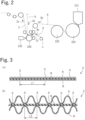
- Fig. 2 is a schematic relevant part view of the stretchable sheet producing device 200.
- the stretchable sheet producing device 200 heats and melts an elastic resin material whose main component is a thermoplastic elastic region having elasticity with an extruder 210, extrudes it into a flat shape from the discharge port of a die 212, and cools it through cooling rollers 220 and 222, thereby forming a resin film 8.
- the stretchable sheet producing device 200 stretches the resin film 8 in the conveyance direction 8x, and disposes and laminates the stretched resin film 8 between two sheet-form sheet members 4 and 6 conveyed in the directions of the arrows 4x and 6x, thereby forming a laminate 2z.
- the sheet members 4 and 6 are, for example, nonwoven fabric sheets.
- the stretchable sheet producing device 200 conveys the laminate 2z along an anvil roller 230, and welds the stretched resin film 8 and the sheet members 4 and 6 together by using an ultrasonic horn 232.
- the stretchable sheet 2 may be formed by welding by heat sealing instead of by the ultrasonic horn 232.
- the stretchable sheet 2 is conveyed in the direction indicated by the arrow 2x with the resin film 8 remaining stretched, and is fed to the stretchable sheet storing device 10 with the resin film 8 remaining stretched.
- Fig. 3 (a) is a schematic cross-sectional view of the stretchable sheet 2 formed by the stretchable sheet producing device 200.
- bonded parts 3 where the resin film 8 and the sheet members 4 and 6 are bonded together are formed with a distance L1 between them in the stretchable sheet 2.
- Fig. 3 (b) is a schematic cross-sectional view of the stretchable sheet 2 when the stretched state is released. As shown in Fig. 3 (b) , when the stretched state is released, the resin film 8 shrinks to make the distance L2 between the bonded parts 3 shorter than the distance L1 in the stretched state, so that the sheet members 4 and 6 undulate.
- the stretchable sheet 2 released from the stretched state stretches when it is pulled, and shrinks when it is stopped being pulled. That is, the stretchable sheet 2 is stretchable.
- the stretchable sheet 2 may have a structure where the sheet member 4 or 6 is disposed and laminated only on one side of the resin film 8, the outer appearances of both sides of the stretchable sheet 2 are made the same when the resin film 8 is disposed and laminated between the two sheet members 4 and 6 as shown in Fig. 3 .
- the sheet members 4 and 6 are conveyed at the stretchable sheet producing device 200 and the stretchable sheet storing device 10. At this time, in order that the sheet members 4 and 6 are conveyed stably, the speed of conveyance of the sheet members 4 and 6 by the stretchable sheet discharger 32 and the speed of conveyance of the sheet members 4 and 6 by the conveyance rollers 21b and 31g are adjusted so that tension is generated on the sheet members 4 and 6. Then, the formation of the resin film 8 is started at the stretchable sheet producing device 200, and the resin film 8 is sandwiched between the sheet members 4 and 6 to form the stretchable sheet 2.
- the speed V 3 of conveyance of the stretchable sheet 2 by the stretchable sheet discharger 32 is made lower than the speeds V 1 and V 2 of conveyance of the stretchable sheet 2 by the conveyance rollers 21b and 31g as in the steady operation state.
- the conveyance speeds V 0 , V 1 , V 2 and V 3 of the conveyance rollers and the like are the same and the tension acting on the sheet members 4 and 6 at the stage of being fed to the stretchable sheet storing device 10 is higher than that at the time of the steady operation.
- the stretchable sheet 2 has no stretchability in a state where no resin film 8 is present because it includes only the two sheet members 4 and 6, and if the conveyance speeds V 0 , V 1 , V 2 and V 3 of the conveyance rollers and the like are different, the sheet members 4 and 6 sag and become entangled with the conveyance rollers and the like.
- the stretchable sheet storing method is provided with a first and second conveying steps.
- the stretchable sheet 2 is received in the stretched state, and conveyed to the stretchable sheet discharger 32. At this time, the stretchable sheet 2 is conveyed by using the conveyance rollers 21b and 31g that define the conveyance speed of the stretchable sheet 2.
- the stretchable sheet discharger 32 conveys the stretchable sheet 2 from the introduction port 32s to the discharge port 32t of the stretchable sheet discharger 32 while holding both sides of the stretchable sheet 2, and folds and stacks the stretchable sheet 2s discharged from the discharge port 32t of the stretchable sheet discharger 32 by reciprocating the discharge port 32t of the stretchable sheet discharger 32 in the first direction in which both side of the stretchable sheet 2 is held.
- the conveyance speed V 3 at which the stretchable sheet discharger 32 conveys the stretchable sheet 2 while holding the stretchable sheet 2 is made lower than the conveyance speeds V 1 and V 2 at which the conveyance rollers 21b and 31g convey the stretchable sheet 2 in the first step.
- the tension of the stretchable sheet 2 released at the time of discharge from the discharge port 32t of the stretchable sheet discharger 32 can be decreased.
- the rapid shrinkage of the stretchable sheet 2e at the time of discharge from the discharge port 32t of the stretchable sheet discharger 32 is inhibited to allow the stretchable sheet 2e to be discharged in a stable state in a desired direction from the discharge port 32t of the stretchable sheet discharger 32, so that the stretchable sheet 2 can be folded and stacked below the discharge port 32t of the stretchable sheet discharger 32.
- the stretchable sheet 2 is conveyed along the conveyance path of the stretchable sheet 2 by a plurality of conveyance rollers 21b and 31g arranged with spacing between them, and the conveyance speed V 2 at which the conveyance roller 31g on the downstream side in the conveyance direction conveys the stretchable sheet 2 is made lower than the conveyance speed V 1 at which the conveyance roller 21b on the upstream side in the conveyance direction conveys the stretchable sheet 2. Since this decreases the tension of the stretchable sheet 2 stepwise, the conveyance speed on the upstream side of the stretchable sheet 2 is easily increased, so that the production efficiency of the stretchable sheet 2 increases.
- the discharge port 32t of the stretchable sheet discharger 32 is reciprocated, while being reciprocated in the first direction, in the third direction crossing the first direction and the second direction in which the stretchable sheet 2 is conveyed while being held by the stretchable sheet discharger 32.
- the stretchable sheet 2s can be stored in a larger amount because the range where the stretchable sheet 2s is folded and stacked is increased.
- the stretchable sheet storing method is further provided with: (iii) a stretchable film forming step in which the resin film 8 is formed by extruding an elastic resin material whose main component is a thermoplastic elastic resin having elasticity, in a state of being heated and melted and the stretchable sheet 2 is formed by laminating the resin film 8 in the stretched state and the sheet-form sheet members 4 and 6.
- the stretchable sheet 2 can be continuously formed, folded and stacked.
- the resin film 8 in the stretched state and the sheet members 4 and 6 are intermittently welded.
- a stretchable sheet can be formed where the sheet members 4 and 6 undulate when the stretched state is released.
- the stretchable sheet 2 is formed by laminating the resin film 8 and the sheet members 4 and 6 so that the resin film 8 is disposed between the two sheet members 4 and 6.
- the outer appearances of both sides of the stretchable sheet 2 can be made the same.
- Fig. 4 is a schematic front view of the stretchable sheet storing device 10.
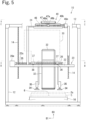
- Fig. 5 is a schematic side view along the line A-A of Fig. 4 .
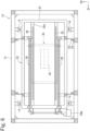
- Fig. 6 is a schematic view along the line B-B of Fig. 5 .
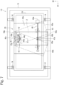
- Fig. 7 is a schematic top view along the line C-C of Fig. 5 , and shows a track shifter 40 in perspective view.
- Fig. 8 is a schematic partial cross-sectional view along the line D-D of Fig. 7 .
- Fig. 9 is a schematic relevant part view of the stretchable sheet storing device 10.
- the stretchable sheet storing device 10 is provided with a first movement unit 20, a second movement unit 30 and the stretchable sheet discharger 32.
- a pallet placement device 16 for disposing a pallet 5 in a placement region 6, the first movement unit 20, the second movement unit 30, the stretchable sheet discharger 32 and the like are disposed inside the main body frame 12 of the stretchable sheet storing device 10.
- the stretchable sheet storing device 10 folds the stretchable sheet discharged from the stretchable sheet discharger 32 and stacks it on top of the pallet 5 disposed in the placement region 6.
- the pallet placement device 16 conveys the pallet 5 with the stretchable sheet stacked thereon from the placement region 6 to a non-illustrated taking-out position.
- the placement region 6 is a predetermined region where the pallet 5 is placed when the stretchable sheet discharged from the stretchable sheet discharger 32 is folded and stacked on top of the pallet 5.
- the stretchable sheet storing device 10 conveys the stretchable sheet 2 continuous in the longitudinal direction, and folds and stacks the stretchable sheet 2 on top of the pallet 5.
- the stretchable sheet 2 is a single or multiple layer sheet, for example, a multiple layer sheet where a resin film having stretchability is sandwiched between two nonwoven fabric sheets and the resin film and the nonwoven fabric sheets are bonded together.
- the first movement unit 20 is disposed above the placement region 6, and is raised/lowered along the main body frame 12 in a third direction 83 facing the placement region 6 as indicated by the arrow 83.
- a first screw shaft 14 extending in the third direction 83 is rotatably supported by the main body frame 12, and a movement member 22 of the first movement unit 20 engages with the first screw shaft 14.
- the first screw shaft 14 is rotated by a first motor 14m, whereby the movement member 22 of the first movement unit 20 moves parallel in the third direction 83.
- a wheel 23 rotatably supported by the first movement unit 20 engages with a first rail 13 fixed to the main body frame 12 and extending in the third direction 83, and moves along the first rail 13.
- the track shifter 40 is disposed to be swingable above the first movement unit 20.
- the track shifter 40 is disposed above the second movement unit 30.
- a reception roller 40p that receives the stretchable sheet 2 is rotatably supported by one end of a frame 40k of the track shifter 40 which frame 40k is U-shaped in cross section, and a discharge roller 40q that discharges the received stretchable sheet 2 is rotatably supported by the other end of the frame 40k.
- the first movement unit 20 supports a plurality of first rollers 21a to 21c. These first rollers 21a to 21c define a first conveyance path 2p where the stretchable sheet 2 guided by a guide roller 11a supported by the main body frame 12 is conveyed to the reception roller 40p of the track shifter 40.
- the second movement unit 30 is supported by the first movement unit 20, and reciprocates along the placement region 6 in a first direction 81 indicated by the arrow 81.
- a pair of second rails 25 are fixed to an upper surface 22a of the horizontally extending movement member 22 of the first movement unit 20, and a pair of second screw shafts 26 are rotatably supported by the movement member 22.
- the second rails 25 and the second screw shafts 26 extend in the first direction 81.
- a second wheel 37 of the second movement unit 30 engages with the second rails 25, and an engagement part 36 of the second movement unit 30 engages with the second screw shafts 26.
- a second motor 26m rotates the second screw shafts 26 to thereby move the second movement unit 30 in the first direction 81.
- the second movement unit 30 supports an upper part of the stretchable sheet discharger 32 to be swingable.
- the stretchable sheet discharger 32 swings between a first and second positions 32p and 32q indicated by broken lines 32p and 32q in Fig. 4 by a third motor 32m.
- the swinging of the stretchable sheet discharger 32 reciprocates the discharge port 32t provided in a lower part of the stretchable sheet discharger 32, along the placement region 6 in a second direction 82 orthogonal to the first direction 81.
- the discharge port 32t discharges the stretchable sheet 2 toward the placement region 6 in such a manner that the width direction of the stretchable sheet 2 is parallel to the first direction 81.
- the second movement unit 30 supports a plurality of second rollers 31a to 31g that define a second conveyance path 2q where the stretchable sheet 2 is conveyed from the discharge roller 40q of the track shifter 40 to the stretchable sheet discharger 32.
- the second movement unit 30 has, on each side of the stretchable sheet discharger 32 in the first direction 81, a pressing member 34 that returnably moves toward the placement region 6.
- the pressing member 34 which is a plate-like member moves from a standby position 34p to a pressing position 34q as indicated by the chain lines 34p and 34q in Fig. 4 by the extension and contraction of an air cylinder 35 fixed to the second movement unit 30, and presses the stretchable sheet 2s folded on top of the pallet 5.
- the pressing members 34 may be provided in the first movement unit 20, providing them in the second movement unit 30 makes it easy to prevent the pressing member 34 from interfering with the stretchable sheet discharger 32.
- the pressing member 34 may be omitted.
- a guide member 42 curved in an arc shape is fixed to an upper surface 24a of an upper member 24 of the first movement unit 20 through a support member 41, and a third screw shaft 46 is rotatably supported by the upper member 24.
- the third screw shaft 46 extends in the first direction 81.
- an engagement member 47 engages with the third screw shaft 46, and a protrusion 47a protruding upward is formed on the engagement member 47.
- two pairs of holding rollers 44a and 44b, and 44p and 44q that hold the arc-shaped guide member 42 from inside and outside in a radial direction are rotatably supported by a lower part on one end side of the frame 40k of the track shifter 40.
- block-shaped holding members 48a and 48b that hold the protrusion 47a of the engagement member 47 from both sides in the first direction 81 are fixed to a lower part on the other end side of the frame 40k of the track shifter 40.
- the track shifter 40 swings as shown by the oblique lines 40a and 40b in Fig. 7 , and the discharge roller 40q of the track shifter 40 moves in the first direction 81. At this time, the track shifter 40 swings about a predetermined position 40x at the center in the width direction of the reception roller 40p in such a manner that the center line of the stretchable sheet 2 that the reception roller 40p receives does not move, on the upstream side of the reception roller 40p.
- the track shifter 40 swings in such a manner that the discharge roller 40q moves in the first direction 81.
- the swinging of the track shifter 40 twists the stretchable sheet 2.
- the first conveyance path 2p upstream of the track shifter 40 is bent by use of the first rollers 21a to 21c supported by the first movement unit 20, thereby making the first conveyance path 2p sufficiently long.
- the second conveyance path 2q from the track shifter 40 to the stretchable sheet discharger 32 is bent by use of the second rollers 31a to 31g supported by the second movement unit 30, thereby making the second conveyance path sufficiently long.
- Bending the first and second conveyance paths 2p and 2q makes it possible to make the first and second conveyance paths 2p and 2q sufficiently long while the increase in dimensions such as the height and width of the stretchable sheet storing device 10 is suppressed.
- Fig. 10 is a schematic relevant part view showing the operation of the stretchable sheet storing device 10.
- the stretchable sheet discharger 32 when the operation is started, the stretchable sheet discharger 32 repeatedly swigs between the position indicated by the solid line and the position indicated by the chain line.
- the stretchable sheet 2 which is conveyed in the direction indicated by the arrow 2i in the stretchable sheet storing device 10 passes through the stretchable sheet discharger 32, and is discharged from the discharge port 32t reciprocating in the second direction 82. By doing this, the stretchable sheet 2s is folded and stacked on top of the pallet 5 placed on the pallet placement device 16.
- the first movement unit 20 is raised as appropriate so that the discharge port 32t of the stretchable sheet discharger 32 is away at an appropriate distance from the stretchable sheet 2s folded and stacked on top of the pallet 5.
- the pressing member 34 presses the stretchable sheet 2s folded and stacked on top of the pallet 5.
- Fig. 11 is a timing chart showing an example of the operation of the stretchable sheet storing device 10.
- the stretchable sheet discharger 32 repeats a regular cycle of swinging.
- the second motor 26m rotates in one direction, so that the second movement unit 30 moves in the first direction 81.
- the second motor 26m stops rotating in one direction, so that the second movement unit 30 stops at a first position.
- N1, N2, K1 and K2 may be either natural numbers or positive real numbers other than natural numbers.
- N1 and N2 may be not equal to each other, and K1 and K2 may be not equal to each other.
- N1 and N2 are large because the movement of the second movement unit 30 can be reduced.
- N1 is equal to or greater than 2 and N2 is equal to or greater than 2
- the number of times of reciprocation of the discharge port 32t of the stretchable sheet discharger 32 in the second direction 82 along the placement region 6 while the second movement unit 30 is stopping at one position is two or more, so that the movement of the second movement unit 30 can be reduced.
- the first movement unit 20 is raised and the pressing member 34 operates as follows:
- the air cylinder 35 is turned on, so that the pressing member 34 is lowered. Then, as shown by reference numeral 62, the air cylinder 35 is turned off, so that the pressing member 34 is raised to return to the original position.
- the air cylinder 35 is turned on, so that the pressing member 34 is lowered. Then, as shown by reference numeral 66, the air cylinder is turned off, so that the pressing member 34 is raised.
- Fig. 12 which is a schematic view along the line X-X of Fig. 10 schematically show a bent part 2v of the stretchable sheet 2s folded and stacked on top of the pallet 5, by the solid lines 2a to 2d.
- a first folded part 2a where the stretchable sheet is newly folded is formed on one side of the pallet 5 in the first direction 81.
- the stretchable sheet discharger 32 swings while moving in the direction indicated by the arrow 32x while the second movement unit 30 is moving from the first position to the second position, whereby first intermediate folded parts 2b and 2c where the stretchable sheet is newly folded are formed.
- the stretchable sheet discharger 32 swings while the second movement unit 30 is stopping at the second position, whereby a second folded part 2d where the stretchable sheet is newly folded is formed on the other side of the pallet 5 in the first direction 81.
- second intermediate folded parts where the stretchable sheet is folded are similarly formed while the second movement unit 30 is moving from the second position to the first position. Then, when the second movement unit 30 stops at the first position, the pressing member 34 is lowered, so that the second folded part 2d is pressed to be compressed.
- the second movement unit 30 stops at the first position and the second position in such a manner that the first folded part 2a and the second folded part 2d are adjacent to each other without overlapping. That is, the second movement unit 30 stops at a plurality of positions, that is, at the first position and the second position at a distance of not less than the width dimension W of the stretchable sheet 2 in the first direction 81.
- the parts 2a and 2d where the sheet is folded while the second movement unit 30 is stopping can be formed at a plurality of positions 4a and 4b on the pallet 5.
- the parts 2a and 2d where the sheet is folded while the second movement unit 30 is stopping are connected together through the parts 2b and 2c where the sheet is folded while the second movement unit 30 is moving, so that the stretchable sheet can be stacked higher than when the stretchable sheet is folded only at one position on the pallet 5. Therefore, by folding and stacking the stretchable sheet 2s at a plurality of positions 4a and 4b on the pallet 5, the frequency of exchanging the pallet 5 can be reduced more than when the stretchable sheet 2s is folded and stacked only at one position on the pallet 5.
- the stretchable sheet 2s when the folded stretchable sheet 2s is undulating, the stretchable sheet 2s can be smoothed out by pressing the folded stretchable sheet 2s by the pressing member 34. By doing this, the stretchable sheet 2s can be stacked higher to thereby further increase the overall length of the stretchable sheet 2s that can be folded and stacked, so that the frequency of pallet exchange can be further reduced.
- the pallet 5 is taken out, and another pallet 5 is placed on the pallet placement device 16. Since it is unnecessary to raise the another pallet 5 placed on the pallet placement device 16 up to a predetermined height, the operation stop time accompanying the pallet exchange can be shortened.
- the second movement unit 30 When the width W of the stretchable sheet 2 is shorter, by stopping the second movement unit 30 at three or more positions, the part where the stretchable sheet is folded while the second movement unit 30 is stopping can be formed at three or more positions on the pallet 5.
- the second movement unit 30 also stops at a plurality of positions at a distance of not less than the width dimension W of the stretchable sheet in the first direction 81.
- the stretchable sheet storing device 10 may have a structure where the second direction 82 is a direction crossing the first direction 81 which direction is other than a direction orthogonal to the first direction 81.
- the stretchable sheet storing device 10 may have a structure where the stretchable sheet 2 is discharged from the discharge port 32t in such a manner that the width direction of the stretchable sheet 2 crosses the second direction 82 without coinciding with the first direction 81.
- the discharge port 32t of the stretchable sheet discharger 32 may be made to reciprocate in the second direction 82 without the stretchable sheet discharger 32 swinging, for example, by the stretchable sheet discharger 32 moving parallel in the second direction 82.
- the stretchable sheet storing device 10 may be operated in various modes.
- the first movement unit 20 may continue moving without repeating moving and stopping.
- the moving and stopping of the second movement unit 30 and the reciprocation of the discharge port 32t may be linked in various modes.
- the stretchable sheet 2 can be folded and stacked while being conveyed in a stretched state.
- the stretchable sheet discharger may have a structure where the stretchable sheet is held by rollers without the use of the endless belts.
- the stretchable sheet storing device may have a structure where stretchable sheets of various configurations are conveyed.
Landscapes
- Engineering & Computer Science (AREA)
- Mechanical Engineering (AREA)
- Textile Engineering (AREA)
- Folding Of Thin Sheet-Like Materials, Special Discharging Devices, And Others (AREA)
Abstract
Description
- The present invention relates to a method and a device for storing a stretchable sheet, and more specifically, relates to a technique for folding and stacking the stretchable sheet.
- For example, a stretchable sheet is known that is formed by stretching a resin film having stretchability in a conveyance direction and laminating another sheet member on the stretched resin film (for example, see Patent Literature 1).
- Moreover, a device is known that folds and stacks sheets.
Fig. 13 is a schematic view of such adevice 101. As shown inFig. 13 , in thisdevice 101, anelongated rubber sheet 111 conveyed by aconveyor 110 passes through astretchable sheet discharger 121 swung by a crank mechanism, is discharged from between a pair ofrollers 121a at the exit side end of thestretchable sheet discharger 121, and is folded to a predetermined length and stacked on top of apallet 131. Thepallet 131 is disposed on a raising/loweringdevice 132, and is lowered when therubber sheet 111 is stacked. Afolding flap 133 holds down the rubber sheet to assist in folding the rubber sheet (for example, see Patent Literature 2). -
- [Patent Literature 1]
WO 2020/090753 A1 - [Patent Literature 2]
JP 2012-236704 A - The inventor of the present application conceived of producing a stretchable sheet as in
Patent Literature 1 and to temporarily store the produced stretchable sheet, discharging the stretchable sheet from the swinging stretchable sheet discharger and folding and stacking the stretchable sheet as inPatent Literature 2. - However, the stretchable sheet is produced in a stretched state, and by the stretched state being released, the sheet member undulates, so that irregularities are formed on the surface of the stretchable sheet. When the stretchable sheet is released from the stretched state and conveyed by the stretchable sheet discharger, the irregularities formed on the surface of the stretchable sheet are flattened.
- On the other hand, the inventor was faced with the following new problem: If the stretchable sheet is conveyed by the stretchable sheet discharger while remaining in the stretched state, the stretchable sheet rapidly shrinks when it is discharged from the stretchable sheet discharger, and the stretchable sheet becomes entangled with the conveyer, so that it is impossible to discharge the stretchable sheet in a zigzag state.
- In view of such circumstances, a problem to be solved by the present invention is to provide a stretchable sheet storing method and device capable of folding and stacking a stretchable sheet while conveying it in a stretched state.
- To solve the above-mentioned problem, the present invention provides a stretchable sheet storing method structured as follows:
- A stretchable sheet storing method is provided with: (i) a first conveying step in which a stretchable sheet is conveyed in a stretched state to an stretchable sheet discharger by using a conveyance roller that defines a conveyance speed of the stretchable sheet; and (ii) a second conveying step in which the stretchable sheet discharger conveys the stretchable sheet from an introduction port to a discharge port of the stretchable sheet discharger while holding both sides of the stretchable sheet in a first direction, and the discharge port of the stretchable sheet discharger reciprocates in the first direction to fold and stack the stretchable sheet discharged from the discharge port of the stretchable sheet discharger. The conveyance speed when the stretchable sheet discharger conveys the stretchable sheet while holding the stretchable sheet in the second conveying step is lower than the conveyance speed when the conveyance roller conveys the stretchable sheet in the first conveying step.
- With the above-described method, the rapid shrinkage of the stretchable sheet at the time of discharge from the discharge port of the stretchable sheet discharger is suppressed to allow the stretchable sheet to be discharged in a stable state from the discharge port of the stretchable sheet discharger in a desired direction, so that the stretchable sheet can be folded and stacked below the discharge port of the stretchable sheet discharger.
- Preferably, in the first conveying step, the stretchable sheet is conveyed along a conveyance path of the stretchable sheet by using a plurality of said conveyance rollers arranged with spacing between them, and a conveyance speed at which the conveyance roller on a downstream side in a conveyance direction conveys the stretchable sheet is made lower than a conveyance speed at which the conveyance roller on an upstream side in the conveyance direction conveys the stretchable sheet.
- In this case, it is easy to increase the conveyance speed of the stretchable sheet on the upstream side of the stretchable sheet discharger.
- Preferably, in the second conveying step, the discharge port of the stretchable sheet discharger reciprocates in the first direction, and reciprocates in a third direction crossing the first direction and a second direction in which the stretchable sheet is conveyed while being held by the stretchable sheet discharger.
- In this case, the range where the stretchable sheet is folded and stacked is increased, so that the stretchable sheet can be stored in a larger amount.
- Preferably, the stretchable sheet storing method is further provided with: (iii) a stretchable film forming step in which a resin film having elasticity is formed by extruding an elastic resin material whose main component is a thermoplastic elastic resin, in a state of being heated and melted and the stretchable sheet is formed by laminating the resin film in the stretched state and a sheet member.
- In this case, the stretchable sheet can be continuously formed, folded and stacked.
- Preferably, in the stretchable sheet forming step, the resin film in the stretched state and the sheet member are intermittently welded.
- In this case, a stretchable sheet can be formed where the sheet member undulates when the stretched state is released.
- Preferably, in the stretchable sheet forming step, the stretchable sheet is formed by laminating the resin film and two of said sheet members so that the resin film is disposed between the sheet members.
- In this case, the outer appearances of both sides of the stretchable sheet can be made the same.
- In addition, to solve the above-mentioned problem, the present invention provides a stretchable sheet storing device structured as follows:
- A stretchable sheet storing device is provided with: (a) a conveyance roller that conveys a stretchable sheet and defines a conveyance speed of the stretchable sheet; and (b) a stretchable sheet discharger that has an introduction port into which the stretchable sheet conveyed by the conveyance roller is introduced and a discharge port from which the stretchable sheet is discharged, and conveys the stretchable sheet from the introduction port to the discharge port while holding both sides of the stretchable sheet in a first direction, the discharge port reciprocating in the first direction so that the stretchable sheet discharged from the discharge port is folded and stacked. A conveyance speed at which the stretchable sheet discharger conveys the stretchable sheet is lower than a conveyance speed at which the conveyance roller conveys the stretchable sheet.
- With the above-described structure, the rapid shrinkage of the stretchable sheet at the time of discharge from the discharge port of the stretchable sheet discharger is suppressed to allow the stretchable sheet to be discharged in a stable state from the discharge port of the stretchable sheet discharger in a desired direction, so that the stretchable sheet can be folded and stacked below the discharge port of the stretchable sheet discharger.
- Preferably, a plurality of said conveyance rollers are arranged with spacing between them, and a conveyance speed at which the conveyance roller on a downstream side in a conveyance direction conveys the stretchable sheet is lower than a conveyance speed at which the conveyance roller on an upstream side in the conveyance direction conveys the stretchable sheet.
- In this case, it is easy to increase the conveyance speed of the stretchable sheet on the upstream side of the stretchable sheet discharger.
- Preferably, the discharge port of the stretchable sheet discharger reciprocates in the first direction and reciprocates in a third direction crossing the first direction and a second direction in which the stretchable sheet is conveyed while being held by the stretchable sheet discharger.
- In this case, since the range where the stretchable sheet is folded and stacked is increased, the stretchable sheet can be stored in a larger amount.
- Preferably, the stretchable sheet includes: a resin film formed of an elastic resin material whose main component is a thermoplastic elastic resin and having elasticity; and a sheet member, the resin film and the sheet member being laminated.
- In this case, the stretchable sheet can be continuously formed, folded and stacked.
- Preferably, in the stretchable sheet, the resin film and the sheet member are intermittently welded.
- In this case, in the stretchable sheet, the sheet member undulates when the stretched state is released.
- Preferably, in the stretchable sheet, the resin film is disposed between two said sheet members.
- In this case, the outer appearances of both sides of the stretchable sheet can be made the same.
- According to the present invention, the stretchable sheet can be folded and stacked while being conveyed in a stretched state.
-
- [
Figure 1] Fig. 1 is a schematic view showing the overall structure (first embodiment). - [
Figure 2] Fig. 2 is a schematic relevant part view of a stretchable sheet producing device (first embodiment). - [
Figure 3] Fig. 3 is a cross-sectional view of a stretchable sheet (first embodiment). - [
Figure 4] Fig. 4 is a schematic front view of a stretchable sheet storing device (first embodiment). - [
Figure 5] Fig. 5 is a schematic side view along the line A-A ofFig. 4 (first embodiment). - [
Figure 6] Fig. 6 is a schematic view along the line B-B ofFig. 5 (first embodiment). - [
Figure 7] Fig. 7 is a schematic top view along the line C-C ofFig. 5 (first embodiment). - [
Figure 8] Fig. 8 is a schematic partial cross-sectional view along the line D-D ofFig. 7 (first embodiment). - [
Figure 9] Fig. 9 is a schematic relevant part view of the stretchable sheet storing device (first embodiment). - [
Figure 10] Fig. 10 is a schematic relevant part view of the stretchable sheet storing device (first embodiment). - [
Figure 11] Fig. 11 is a timing chart showing the operation of the stretchable sheet storing device (first embodiment). - [
Figure 12] Fig. 12 is a schematic view along the line X-X ofFig. 10 (first embodiment). - [
Figure 13] Fig. 13 is a schematic view of the stretchable sheet storing device (first conventional example). - Hereinafter, an embodiment of the present invention will be described with reference to the drawings.
- [First embodiment] A stretchable sheet storing method and device of a first embodiment will be described with reference to
Figs. 1 to 12 . -
Fig. 1 is a schematic view showing the overall structure. As shown inFig. 1 , to a stretchablesheet storing device 10, a sheet that is stretchable, or astretchable sheet 2 is supplied in a stretched state from a stretchablesheet producing device 200. - In the stretchable
sheet storing device 10, a plurality of rollers includingconveyance rollers Fig. 1 , somerollers stretchable sheet 2. Theconveyance rollers stretchable sheet 2, and define the conveyance speed of thestretchable sheet 2. That is, theconveyance rollers stretchable sheet 2 in contact with the outer peripheral surfaces of theconveyance rollers conveyance rollers - The stretchable
sheet storing device 10 is further provided with astretchable sheet discharger 32. Thestretchable sheet discharger 32 has anintroduction port 32s into which thestretchable sheet 2 conveyed by theconveyance rollers discharge port 32t from which thestretchable sheet 2 is discharged, and conveys thestretchable sheet 2 from theintroduction port 32s to thedischarge port 32t while holding both sides of thestretchable sheet 2. Thestretchable sheet discharger 32 swings in the direction indicated by thearrow 32r, and reciprocates between the position indicated by the solid line and the position indicated by the chain line. This reciprocates thedischarge port 32t of thestretchable sheet discharger 32 in a direction in which both sides of thestretchable sheet 2 are held, astretchable sheet 2e continuously discharged from thedischarge port 32t is zigzagged, and astretchable sheet 2s is folded and stacked on a non-illustrated pallet disposed below thedischarge port 32t of thestretchable sheet discharger 32. - The
stretchable sheet 2 is produced by the stretchablesheet producing device 200, and is fed to the stretchablesheet storing device 10. When the conveyance speed of thestretchable sheet 2 when thestretchable sheet 2 is fed from the stretchablesheet producing device 200 to the stretchablesheet storing device 10 is V0, the peripheral speed of theconveyance roller 21b on the upstream side in the conveyance direction, that is, the conveyance speed at which theconveyance roller 21b conveys thestretchable sheet 2 is V1, the peripheral speed of theconveyance roller 31g on the downstream side, that is, the conveyance speed at which theconveyance roller 31g conveys thestretchable sheet 2 is V2 and the conveyance speed at which thestretchable sheet discharger 32 conveys thestretchable sheet 2 is V3, theconveyance rollers stretchable sheet discharger 32 are driven so that the followingexpression 1 is satisfied:
- For example, the
conveyance rollers stretchable sheet discharger 32 drive so that the followingexpressions 2 to 4 are satisfied:


- By making the conveyance speed V3 at which the
stretchable sheet discharger 32 conveys thestretchable sheet 2 lower than the conveyance speeds V1 and V2 at which theconveyance rollers stretchable sheet 2, the stretch ratio of thestretchable sheet 2 when thestretchable sheet 2 is conveyed by thestretchable sheet discharger 32 can be made lower than the stretch ratio of thestretchable sheet 2 when the stretchablesheet storing device 10 receives thestretchable sheet 2 from the stretchablesheet producing device 200. The stretch ratio is defined by, for example, ΔL/L when the natural length when no tension acts externally is L and the length when tension acts to stretchstretchable sheet 2 from the natural length is L+ΔL. The lower the stretch ratio is, the lower the tension acting on thestretchable sheet 2 is. - Since the
stretchable sheet discharger 32 conveys thestretchable sheet 2 with a stretch ratio lower than that when thestretchable sheet 2 is fed to the stretchablesheet storing device 10, the tension of thestretchable sheet 2 released at the time of discharge from thedischarge port 32t of thestretchable sheet discharger 32 can be made low. When the tension of thestretchable sheet 2 released at the time of discharge from thedischarge port 32t of thestretchable sheet discharger 32 is made low, the rapid shrinkage of thestretchable sheet 2e at the time of discharge from thedischarge port 32t of thestretchable sheet discharger 32 is suppressed to allow thestretchable sheet 2e to be discharged in a stable state from thedischarge port 32t of thestretchable sheet discharger 32 in a desired direction, so that thestretchable sheet 2s can be folded and stacked on top of the non-illustrated pallet disposed below thedischarge port 32t of thestretchable sheet discharger 32. - It is essential for the stretchable
sheet storing device 10 to have at least oneconveyance roller 21b and thestretchable sheet discharger 32. The other rollers may be omitted. - In the case where the stretchable
sheet storing device 10 has a plurality ofconveyance rollers conveyance rollers conveyance roller 31g on the downstream side in the conveyance direction conveys thestretchable sheet 2 is made lower than the conveyance speed V1 at which theconveyance roller 21b on the upstream side in the conveyance direction conveys thestretchable sheet 2. Since this makes the tension of thestretchable sheet 2 decrease stepwise, the conveyance of thestretchable sheet 2 is easy to stabilize. This makes it easy to increase the conveyance speeds V0, V1 and V3 of thestretchable sheet 2 on the upstream side of thestretchable sheet discharger 32. Consequently, it is easy to increase the conveyance speed of thestretchable sheet 2 to increase production efficiency. - The
stretchable sheet discharger 32 and the like of the stretchablesheet storing device 10 are raised to the position indicated by the broken line and protrude from amain body frame 12 as indicated by thearrow 32x. This allows thestretchable sheet 2s to be stacked higher. Instead of thestretchable sheet discharger 32 and the like being raised, the placement part where thestretchable sheet 2s is folded and stacked may be lowered, or the placement part may be kept stopped. - While details will be provided later, it is preferable for the
stretchable sheet discharger 32 to reciprocate also in a direction perpendicular to the paper inFig. 1 . In this case, while reciprocating in a first direction in which both sides of thestretchable sheet 2 is held, thedischarge port 32t of thestretchable sheet discharger 32 reciprocates in a third direction crossing the first direction and a second direction in which thestretchable sheet 2 is conveyed while being held by the stretchable sheet discharger. Since this increases the range where thestretchable sheet 2s is folded and stacked, thestretchable sheet 2s can be stored in a larger amount. -
Fig. 2 is a schematic relevant part view of the stretchablesheet producing device 200. As shown inFigs. 1 and2 , the stretchablesheet producing device 200 heats and melts an elastic resin material whose main component is a thermoplastic elastic region having elasticity with anextruder 210, extrudes it into a flat shape from the discharge port of adie 212, and cools it through coolingrollers resin film 8. Then, the stretchablesheet producing device 200 stretches theresin film 8 in theconveyance direction 8x, and disposes and laminates the stretchedresin film 8 between two sheet-form sheet members arrows 4x and 6x, thereby forming a laminate 2z. Thesheet members sheet producing device 200 conveys the laminate 2z along ananvil roller 230, and welds the stretchedresin film 8 and thesheet members ultrasonic horn 232. Thestretchable sheet 2 may be formed by welding by heat sealing instead of by theultrasonic horn 232. Thestretchable sheet 2 is conveyed in the direction indicated by thearrow 2x with theresin film 8 remaining stretched, and is fed to the stretchablesheet storing device 10 with theresin film 8 remaining stretched. -
Fig. 3 (a) is a schematic cross-sectional view of thestretchable sheet 2 formed by the stretchablesheet producing device 200. By the periodical welding using theultrasonic horn 232, as shown inFig. 3 (a) , bondedparts 3 where theresin film 8 and thesheet members stretchable sheet 2. -
Fig. 3 (b) is a schematic cross-sectional view of thestretchable sheet 2 when the stretched state is released. As shown inFig. 3 (b) , when the stretched state is released, theresin film 8 shrinks to make the distance L2 between the bondedparts 3 shorter than the distance L1 in the stretched state, so that thesheet members - Since the
resin film 8 is formed of the elastic resin material whose main component is the thermoplastic elastic resin having elasticity and has elasticity, thestretchable sheet 2 released from the stretched state stretches when it is pulled, and shrinks when it is stopped being pulled. That is, thestretchable sheet 2 is stretchable. - While the
stretchable sheet 2 may have a structure where thesheet member resin film 8, the outer appearances of both sides of thestretchable sheet 2 are made the same when theresin film 8 is disposed and laminated between the twosheet members Fig. 3 . - At the start of the production of the
stretchable sheet 2, first, only thesheet members sheet producing device 200 and the stretchablesheet storing device 10. At this time, in order that thesheet members sheet members stretchable sheet discharger 32 and the speed of conveyance of thesheet members conveyance rollers sheet members resin film 8 is started at the stretchablesheet producing device 200, and theresin film 8 is sandwiched between thesheet members stretchable sheet 2. - During the time from when the production of the
stretchable sheet 2 is started at the stretchablesheet producing device 200 to when the steady operation state is reached, the speed V3 of conveyance of thestretchable sheet 2 by thestretchable sheet discharger 32 is made lower than the speeds V1 and V2 of conveyance of thestretchable sheet 2 by theconveyance rollers - Before the start of the steady operation, only the two
sheet members resin film 8 is extruded, and in this state, preferably, the conveyance speeds V0, V1, V2 and V3 of the conveyance rollers and the like are the same and the tension acting on thesheet members sheet storing device 10 is higher than that at the time of the steady operation. This is in order to prevent the following: Thestretchable sheet 2 has no stretchability in a state where noresin film 8 is present because it includes only the twosheet members sheet members - Next, a stretchable sheet storing method will be described. The stretchable sheet storing method is provided with a first and second conveying steps.
- In the first conveying step, the
stretchable sheet 2 is received in the stretched state, and conveyed to thestretchable sheet discharger 32. At this time, thestretchable sheet 2 is conveyed by using theconveyance rollers stretchable sheet 2. - In the second conveying step, the
stretchable sheet discharger 32 conveys thestretchable sheet 2 from theintroduction port 32s to thedischarge port 32t of thestretchable sheet discharger 32 while holding both sides of thestretchable sheet 2, and folds and stacks thestretchable sheet 2s discharged from thedischarge port 32t of thestretchable sheet discharger 32 by reciprocating thedischarge port 32t of thestretchable sheet discharger 32 in the first direction in which both side of thestretchable sheet 2 is held. At this time, the conveyance speed V3 at which thestretchable sheet discharger 32 conveys thestretchable sheet 2 while holding thestretchable sheet 2 is made lower than the conveyance speeds V1 and V2 at which theconveyance rollers stretchable sheet 2 in the first step. - By making the conveyance speed V3 at which the
stretchable sheet discharger 32 conveys thestretchable sheet 2 lower than the conveyance speeds V1 and V2 at which theconveyance rollers stretchable sheet 2 as described above, the tension of thestretchable sheet 2 released at the time of discharge from thedischarge port 32t of thestretchable sheet discharger 32 can be decreased. By decreasing the tension of thestretchable sheet 2 released when thestretchable sheet 2 is discharged from thedischarge port 32t of thestretchable sheet discharger 32, the rapid shrinkage of thestretchable sheet 2e at the time of discharge from thedischarge port 32t of thestretchable sheet discharger 32 is inhibited to allow thestretchable sheet 2e to be discharged in a stable state in a desired direction from thedischarge port 32t of thestretchable sheet discharger 32, so that thestretchable sheet 2 can be folded and stacked below thedischarge port 32t of thestretchable sheet discharger 32. - In the first conveying step, the
stretchable sheet 2 is conveyed along the conveyance path of thestretchable sheet 2 by a plurality ofconveyance rollers conveyance roller 31g on the downstream side in the conveyance direction conveys thestretchable sheet 2 is made lower than the conveyance speed V1 at which theconveyance roller 21b on the upstream side in the conveyance direction conveys thestretchable sheet 2. Since this decreases the tension of thestretchable sheet 2 stepwise, the conveyance speed on the upstream side of thestretchable sheet 2 is easily increased, so that the production efficiency of thestretchable sheet 2 increases. - In the second conveying step, the
discharge port 32t of thestretchable sheet discharger 32 is reciprocated, while being reciprocated in the first direction, in the third direction crossing the first direction and the second direction in which thestretchable sheet 2 is conveyed while being held by thestretchable sheet discharger 32. In this case, thestretchable sheet 2s can be stored in a larger amount because the range where thestretchable sheet 2s is folded and stacked is increased. - The stretchable sheet storing method is further provided with: (iii) a stretchable film forming step in which the
resin film 8 is formed by extruding an elastic resin material whose main component is a thermoplastic elastic resin having elasticity, in a state of being heated and melted and thestretchable sheet 2 is formed by laminating theresin film 8 in the stretched state and the sheet-form sheet members - In this case, the
stretchable sheet 2 can be continuously formed, folded and stacked. - In the stretchable sheet forming step, the
resin film 8 in the stretched state and thesheet members sheet members - In the stretchable sheet forming step, the
stretchable sheet 2 is formed by laminating theresin film 8 and thesheet members resin film 8 is disposed between the twosheet members stretchable sheet 2 can be made the same. - Hereinafter, the stretchable
sheet storing device 10 will be described in more detail with reference toFigs. 4 to 12 . -
Fig. 4 is a schematic front view of the stretchablesheet storing device 10.Fig. 5 is a schematic side view along the line A-A ofFig. 4 .Fig. 6 is a schematic view along the line B-B ofFig. 5 .Fig. 7 is a schematic top view along the line C-C ofFig. 5 , and shows atrack shifter 40 in perspective view.Fig. 8 is a schematic partial cross-sectional view along the line D-D ofFig. 7 .Fig. 9 is a schematic relevant part view of the stretchablesheet storing device 10. - As shown in
Figs. 4 to 9 , the stretchablesheet storing device 10 is provided with afirst movement unit 20, asecond movement unit 30 and thestretchable sheet discharger 32. Apallet placement device 16 for disposing apallet 5 in aplacement region 6, thefirst movement unit 20, thesecond movement unit 30, thestretchable sheet discharger 32 and the like are disposed inside themain body frame 12 of the stretchablesheet storing device 10. - While details will be provided later, the stretchable
sheet storing device 10 folds the stretchable sheet discharged from thestretchable sheet discharger 32 and stacks it on top of thepallet 5 disposed in theplacement region 6. Thepallet placement device 16 conveys thepallet 5 with the stretchable sheet stacked thereon from theplacement region 6 to a non-illustrated taking-out position. Theplacement region 6 is a predetermined region where thepallet 5 is placed when the stretchable sheet discharged from thestretchable sheet discharger 32 is folded and stacked on top of thepallet 5. - The stretchable
sheet storing device 10 conveys thestretchable sheet 2 continuous in the longitudinal direction, and folds and stacks thestretchable sheet 2 on top of thepallet 5. Thestretchable sheet 2 is a single or multiple layer sheet, for example, a multiple layer sheet where a resin film having stretchability is sandwiched between two nonwoven fabric sheets and the resin film and the nonwoven fabric sheets are bonded together. - The
first movement unit 20 is disposed above theplacement region 6, and is raised/lowered along themain body frame 12 in athird direction 83 facing theplacement region 6 as indicated by thearrow 83. Specifically, afirst screw shaft 14 extending in thethird direction 83 is rotatably supported by themain body frame 12, and amovement member 22 of thefirst movement unit 20 engages with thefirst screw shaft 14. Thefirst screw shaft 14 is rotated by afirst motor 14m, whereby themovement member 22 of thefirst movement unit 20 moves parallel in thethird direction 83. Awheel 23 rotatably supported by thefirst movement unit 20 engages with afirst rail 13 fixed to themain body frame 12 and extending in thethird direction 83, and moves along thefirst rail 13. - The
track shifter 40 is disposed to be swingable above thefirst movement unit 20. Thetrack shifter 40 is disposed above thesecond movement unit 30. Areception roller 40p that receives thestretchable sheet 2 is rotatably supported by one end of aframe 40k of thetrack shifter 40 whichframe 40k is U-shaped in cross section, and adischarge roller 40q that discharges the receivedstretchable sheet 2 is rotatably supported by the other end of theframe 40k. - The
first movement unit 20 supports a plurality offirst rollers 21a to 21c. Thesefirst rollers 21a to 21c define afirst conveyance path 2p where thestretchable sheet 2 guided by aguide roller 11a supported by themain body frame 12 is conveyed to thereception roller 40p of thetrack shifter 40. - The
second movement unit 30 is supported by thefirst movement unit 20, and reciprocates along theplacement region 6 in afirst direction 81 indicated by thearrow 81. Specifically, as shown inFigs. 5 and6 , a pair ofsecond rails 25 are fixed to anupper surface 22a of the horizontally extendingmovement member 22 of thefirst movement unit 20, and a pair ofsecond screw shafts 26 are rotatably supported by themovement member 22. The second rails 25 and thesecond screw shafts 26 extend in thefirst direction 81. Asecond wheel 37 of thesecond movement unit 30 engages with thesecond rails 25, and anengagement part 36 of thesecond movement unit 30 engages with thesecond screw shafts 26. Asecond motor 26m rotates thesecond screw shafts 26 to thereby move thesecond movement unit 30 in thefirst direction 81. - The
second movement unit 30 supports an upper part of thestretchable sheet discharger 32 to be swingable. Thestretchable sheet discharger 32 swings between a first andsecond positions broken lines Fig. 4 by athird motor 32m. The swinging of thestretchable sheet discharger 32 reciprocates thedischarge port 32t provided in a lower part of thestretchable sheet discharger 32, along theplacement region 6 in asecond direction 82 orthogonal to thefirst direction 81. Thedischarge port 32t discharges thestretchable sheet 2 toward theplacement region 6 in such a manner that the width direction of thestretchable sheet 2 is parallel to thefirst direction 81. - As shown in
Fig. 9 , thestretchable sheet discharger 32 has twoconveyors conveyors endless belt 33v circulating in a direction indicated by thearrow 33x alongguide rollers 33p and 33q and adrive roller 33d. Thestretchable sheet 2 is conveyed while being sandwiched between theendless belts 33v of theconveyors arrow 2x from thedischarger 32t between end parts, on the downstream side in the conveyance direction, of facing parts of theendless belts 33v of theconveyors drive rollers 33d of theconveyors conveyor motors Fig. 4 . - The
second movement unit 30 supports a plurality ofsecond rollers 31a to 31g that define asecond conveyance path 2q where thestretchable sheet 2 is conveyed from thedischarge roller 40q of thetrack shifter 40 to thestretchable sheet discharger 32. - As shown in
Fig. 5 , thesecond movement unit 30 has, on each side of thestretchable sheet discharger 32 in thefirst direction 81, a pressingmember 34 that returnably moves toward theplacement region 6. For example, the pressingmember 34 which is a plate-like member moves from astandby position 34p to apressing position 34q as indicated by thechain lines Fig. 4 by the extension and contraction of anair cylinder 35 fixed to thesecond movement unit 30, and presses thestretchable sheet 2s folded on top of thepallet 5. - While the
pressing members 34 may be provided in thefirst movement unit 20, providing them in thesecond movement unit 30 makes it easy to prevent the pressingmember 34 from interfering with thestretchable sheet discharger 32. The pressingmember 34 may be omitted. - When the
second movement unit 30 moves in thefirst direction 81, the conveyance direction of thestretchable sheet 2 shifts in the width direction of thestretchable sheet 2. Thetrack shifter 40 swings in response to this shift. - Specifically, as shown in
Figs. 7 and8 , aguide member 42 curved in an arc shape is fixed to anupper surface 24a of anupper member 24 of thefirst movement unit 20 through asupport member 41, and athird screw shaft 46 is rotatably supported by theupper member 24. Thethird screw shaft 46 extends in thefirst direction 81. As shown inFig. 5 , anengagement member 47 engages with thethird screw shaft 46, and aprotrusion 47a protruding upward is formed on theengagement member 47. - As shown in
Figs. 7 and8 , two pairs of holdingrollers guide member 42 from inside and outside in a radial direction are rotatably supported by a lower part on one end side of theframe 40k of thetrack shifter 40. As shown inFigs. 5 and7 , block-shapedholding members protrusion 47a of theengagement member 47 from both sides in thefirst direction 81 are fixed to a lower part on the other end side of theframe 40k of thetrack shifter 40. - When the
third screw shaft 46 is rotated by athird motor 46m, theengagement member 47 moves along thethird screw shaft 46. In response thereto, thetrack shifter 40 swings as shown by theoblique lines Fig. 7 , and thedischarge roller 40q of thetrack shifter 40 moves in thefirst direction 81. At this time, thetrack shifter 40 swings about apredetermined position 40x at the center in the width direction of thereception roller 40p in such a manner that the center line of thestretchable sheet 2 that thereception roller 40p receives does not move, on the upstream side of thereception roller 40p. - In tandem with the movement of the
second movement unit 30 in thefirst direction 81, thetrack shifter 40 swings in such a manner that thedischarge roller 40q moves in thefirst direction 81. The swinging of thetrack shifter 40 twists thestretchable sheet 2. To absorb this twist, thefirst conveyance path 2p upstream of thetrack shifter 40 is bent by use of thefirst rollers 21a to 21c supported by thefirst movement unit 20, thereby making thefirst conveyance path 2p sufficiently long. Thesecond conveyance path 2q from thetrack shifter 40 to thestretchable sheet discharger 32 is bent by use of thesecond rollers 31a to 31g supported by thesecond movement unit 30, thereby making the second conveyance path sufficiently long. By doing this, thestretchable sheet 2 can be stably conveyed even though thesecond movement unit 30 moves. - Bending the first and
second conveyance paths second conveyance paths sheet storing device 10 is suppressed. - Next, the operation of the stretchable
sheet storing device 10 will be described with reference toFigs. 10 through Fig. 12 . -
Fig. 10 is a schematic relevant part view showing the operation of the stretchablesheet storing device 10. As shown inFig. 10 , when the operation is started, thestretchable sheet discharger 32 repeatedly swigs between the position indicated by the solid line and the position indicated by the chain line. Thestretchable sheet 2 which is conveyed in the direction indicated by the arrow 2i in the stretchablesheet storing device 10 passes through thestretchable sheet discharger 32, and is discharged from thedischarge port 32t reciprocating in thesecond direction 82. By doing this, thestretchable sheet 2s is folded and stacked on top of thepallet 5 placed on thepallet placement device 16. - The
first movement unit 20 is raised as appropriate so that thedischarge port 32t of thestretchable sheet discharger 32 is away at an appropriate distance from thestretchable sheet 2s folded and stacked on top of thepallet 5. The pressingmember 34 presses thestretchable sheet 2s folded and stacked on top of thepallet 5. -
Fig. 11 is a timing chart showing an example of the operation of the stretchablesheet storing device 10. As shown byreference numeral 50 inFig. 11 , thestretchable sheet discharger 32 repeats a regular cycle of swinging. As shown byreference numeral 51, thesecond motor 26m rotates in one direction, so that thesecond movement unit 30 moves in thefirst direction 81. - Then, as shown by
reference numeral 52, thesecond motor 26m stops rotating in one direction, so that thesecond movement unit 30 stops at a first position. When thestretchable sheet discharger 32 completes N1 cycles of swinging (N1=8 inFig. 11 ) while thesecond movement unit 30 is stopping, as shown byreference numeral 54, thesecond motor 26m rotates in the reverse direction, so that thesecond movement unit 30 moves from the first position. - When the
stretchable sheet discharger 32 completes K1 cycles of swinging (K1=2 inFig. 11 ) while thesecond movement unit 30 is moving, as shown byreference numeral 56, thesecond motor 26m stops rotating in the reverse direction, so that thesecond movement unit 30 stops at a second position. When thestretchable sheet discharger 32 completes N2 cycles of swinging (N2=8 inFig. 11 ) while thesecond movement unit 30 is stopping, as shown byreference numeral 58, thesecond motor 26m rotates in one direction, so that thesecond movement unit 30 moves from the second position. - Then, when the
stretchable sheet discharger 32 completes K2 cycles of swinging (K2=2 inFig. 11 ) while thesecond movement unit 30 is moving, as shown byreference numeral 59, thesecond motor 26m stops rotating in one direction, so that thesecond movement unit 30 stops at the first position. Similar operations are repeated thereafter. - N1, N2, K1 and K2 may be either natural numbers or positive real numbers other than natural numbers. N1 and N2 may be not equal to each other, and K1 and K2 may be not equal to each other.
- It is preferable that N1 and N2 are large because the movement of the
second movement unit 30 can be reduced. For example, when N1 is equal to or greater than 2 and N2 is equal to or greater than 2, the number of times of reciprocation of thedischarge port 32t of thestretchable sheet discharger 32 in thesecond direction 82 along theplacement region 6 while thesecond movement unit 30 is stopping at one position is two or more, so that the movement of thesecond movement unit 30 can be reduced. - In conjunction with the operation of the
second movement unit 30, thefirst movement unit 20 is raised and the pressingmember 34 operates as follows: - When the
second movement unit 30 moves and stops at the first position, as shown byreference numeral 60, theair cylinder 35 is turned on, so that the pressingmember 34 is lowered. Then, as shown byreference numeral 62, theair cylinder 35 is turned off, so that the pressingmember 34 is raised to return to the original position. - Moreover, as shown by
reference numeral 70, when theair cylinder 35 switches from on to off while thesecond movement unit 30 moves and stops at the first position, thefirst motor 14m is turned on, so that thefirst movement unit 20 is raised. Then, as shown byreference numeral 72, thefirst motor 14m is turned off, so that thefirst movement unit 20 stops. - When the
second movement unit 30 moves and stops at the second position, as shown byreference numeral 64, theair cylinder 35 is turned on, so that the pressingmember 34 is lowered. Then, as shown byreference numeral 66, the air cylinder is turned off, so that the pressingmember 34 is raised. - Similarly, when the
second movement unit 30 stops, the pressingmember 34 is lowered. Moreover, each time thesecond movement unit 30 reciprocates between the first and second positions, thefirst movement unit 20 is raised. -
Fig. 12 which is a schematic view along the line X-X ofFig. 10 schematically show abent part 2v of thestretchable sheet 2s folded and stacked on top of thepallet 5, by thesolid lines 2a to 2d. - As shown in
Fig. 12 (a) , when thestretchable sheet discharger 32 swings while thesecond movement unit 30 is stopping at the first position, a first foldedpart 2a where the stretchable sheet is newly folded is formed on one side of thepallet 5 in thefirst direction 81. - Then, as shown in
Fig. 12 (b) , thestretchable sheet discharger 32 swings while moving in the direction indicated by thearrow 32x while thesecond movement unit 30 is moving from the first position to the second position, whereby first intermediate foldedparts - Then, as shown in
Fig. 12 (c) , when thesecond movement unit 30 stops at the second position, the pressingmember 34 is lowered, so that the first foldedpart 2a is pressed to be compressed. For example, an undulating part between opposing foldedparts Fig. 10 is pressed to be flattened. Although not shown inFig. 12 (c) , while this is being done, the stretchable sheet is newly folded on the other side of thepallet 5 in thefirst direction 81. - As shown in
Fig. 12 (d) , thestretchable sheet discharger 32 swings while thesecond movement unit 30 is stopping at the second position, whereby a second foldedpart 2d where the stretchable sheet is newly folded is formed on the other side of thepallet 5 in thefirst direction 81. - Although not shown, thereafter, second intermediate folded parts where the stretchable sheet is folded are similarly formed while the
second movement unit 30 is moving from the second position to the first position. Then, when thesecond movement unit 30 stops at the first position, the pressingmember 34 is lowered, so that the second foldedpart 2d is pressed to be compressed. - The
second movement unit 30 stops at the first position and the second position in such a manner that the first foldedpart 2a and the second foldedpart 2d are adjacent to each other without overlapping. That is, thesecond movement unit 30 stops at a plurality of positions, that is, at the first position and the second position at a distance of not less than the width dimension W of thestretchable sheet 2 in thefirst direction 81. - When the width W of the
stretchable sheet 2 is not more than half of the dimension T of thepallet 5 in thefirst direction 81, theparts second movement unit 30 is stopping can be formed at a plurality ofpositions pallet 5. Theparts second movement unit 30 is stopping are connected together through theparts second movement unit 30 is moving, so that the stretchable sheet can be stacked higher than when the stretchable sheet is folded only at one position on thepallet 5. Therefore, by folding and stacking thestretchable sheet 2s at a plurality ofpositions pallet 5, the frequency of exchanging thepallet 5 can be reduced more than when thestretchable sheet 2s is folded and stacked only at one position on thepallet 5. - For example, when the folded
stretchable sheet 2s is undulating, thestretchable sheet 2s can be smoothed out by pressing the foldedstretchable sheet 2s by the pressingmember 34. By doing this, thestretchable sheet 2s can be stacked higher to thereby further increase the overall length of thestretchable sheet 2s that can be folded and stacked, so that the frequency of pallet exchange can be further reduced. - When the stacking of the
stretchable sheet 2s is completed, thepallet 5 is taken out, and anotherpallet 5 is placed on thepallet placement device 16. Since it is unnecessary to raise the anotherpallet 5 placed on thepallet placement device 16 up to a predetermined height, the operation stop time accompanying the pallet exchange can be shortened. - When the width W of the
stretchable sheet 2 is shorter, by stopping thesecond movement unit 30 at three or more positions, the part where the stretchable sheet is folded while thesecond movement unit 30 is stopping can be formed at three or more positions on thepallet 5. In this case, thesecond movement unit 30 also stops at a plurality of positions at a distance of not less than the width dimension W of the stretchable sheet in thefirst direction 81. - While in the first embodiment, a case is shown where the
second direction 82 is orthogonal to thefirst direction 81, the stretchablesheet storing device 10 may have a structure where thesecond direction 82 is a direction crossing thefirst direction 81 which direction is other than a direction orthogonal to thefirst direction 81. While in the first embodiment, a case is shown where thestretchable sheet 2 is discharged from thedischarge port 32t of thestretchable sheet discharger 32 in such a manner that the width direction of thestretchable sheet 2 coincides with thefirst direction 81, the stretchablesheet storing device 10 may have a structure where thestretchable sheet 2 is discharged from thedischarge port 32t in such a manner that the width direction of thestretchable sheet 2 crosses thesecond direction 82 without coinciding with thefirst direction 81. - Moreover, the
discharge port 32t of thestretchable sheet discharger 32 may be made to reciprocate in thesecond direction 82 without thestretchable sheet discharger 32 swinging, for example, by thestretchable sheet discharger 32 moving parallel in thesecond direction 82. - The stretchable
sheet storing device 10 may be operated in various modes. For example, thefirst movement unit 20 may continue moving without repeating moving and stopping. The moving and stopping of thesecond movement unit 30 and the reciprocation of thedischarge port 32t may be linked in various modes. - [Summary] As described above, the
stretchable sheet 2 can be folded and stacked while being conveyed in a stretched state. - The present invention is not limited to the above-described embodiment but may be carried out with various modifications being added.
- For example, the stretchable sheet discharger may have a structure where the stretchable sheet is held by rollers without the use of the endless belts. The stretchable sheet storing device may have a structure where stretchable sheets of various configurations are conveyed.
-
- 2, 2e Stretchable sheet
- 4, 6 Sheet member
- 8 Resin film
- 10 Stretchable sheet storing device
- 21b Conveyance roller (conveyance roller on the upstream side in the conveyance direction)
- 31g Conveyance roller (conveyance roller on the downstream side in the conveyance direction)
- 32 Stretchable sheet discharger
- 32s Introduction port
- 32t Discharge port
- V1 to V3 Conveyance speed
Claims (12)
- A stretchable sheet storing method comprising:a first conveying step in which a stretchable sheet is conveyed in a stretched state to an stretchable sheet discharger by using a conveyance roller that defines a conveyance speed of the stretchable sheet; anda second conveying step in which the stretchable sheet discharger conveys the stretchable sheet from an introduction port to a discharge port of the stretchable sheet discharger while holding both sides of the stretchable sheet in a first direction, and the discharge port of the stretchable sheet discharger reciprocates in the first direction to fold and stack the stretchable sheet discharged from the discharge port of the stretchable sheet discharger,wherein the conveyance speed when the stretchable sheet discharger conveys the stretchable sheet while holding the stretchable sheet in the second conveying step is lower than the conveyance speed when the conveyance roller conveys the stretchable sheet in the first conveying step.
- The stretchable sheet storing method according to claim 1, wherein in the first conveying step, the stretchable sheet is conveyed along a conveyance path of the stretchable sheet by using a plurality of said conveyance rollers arranged with spacing between them, and a conveyance speed at which the conveyance roller on a downstream side in a conveyance direction conveys the stretchable sheet is made lower than a conveyance speed at which the conveyance roller on an upstream side in the conveyance direction conveys the stretchable sheet.
- The stretchable sheet storing method according to claim 1 or 2, wherein in the second conveying step, the discharge port of the stretchable sheet discharger reciprocates in the first direction, and reciprocates in a third direction crossing the first direction and a second direction in which the stretchable sheet is conveyed while being held by the stretchable sheet discharger.
- The stretchable sheet storing method according to any one of claims 1 to 3, further comprising a stretchable film forming step in which a resin film having elasticity is formed by extruding an elastic resin material whose main component is a thermoplastic elastic resin, in a state of being heated and melted and the stretchable sheet is formed by laminating the resin film in the stretched state and a sheet member.
- The stretchable sheet storing method according to claim 4, wherein in the stretchable sheet forming step, the resin film in the stretched state and the sheet member are intermittently welded.
- The stretchable sheet storing method according to claim 4 or 5, wherein in the stretchable sheet forming step, the stretchable sheet is formed by laminating the resin film and two of said sheet members so that the resin film is disposed between the sheet members.
- A stretchable sheet storing device comprising:a conveyance roller that conveys a stretchable sheet and defines a conveyance speed of the stretchable sheet; anda stretchable sheet discharger that has an introduction port into which the stretchable sheet conveyed by the conveyance roller is introduced and a discharge port from which the stretchable sheet is discharged, and conveys the stretchable sheet from the introduction port to the discharge port while holding both sides of the stretchable sheet in a first direction, the discharge port reciprocating in the first direction so that the stretchable sheet discharged from the discharge port is folded and stacked,wherein a conveyance speed at which the stretchable sheet discharger conveys the stretchable sheet is lower than a conveyance speed at which the conveyance roller conveys the stretchable sheet.
- The stretchable sheet storing device according to claim 7, wherein a plurality of said conveyance rollers are arranged with spacing between them, and
a conveyance speed at which the conveyance roller on a downstream side in a conveyance direction conveys the stretchable sheet is lower than a conveyance speed at which the conveyance roller on an upstream side in the conveyance direction conveys the stretchable sheet. - The stretchable sheet storing device according to claim 7 or 8, wherein the discharge port of the stretchable sheet discharger reciprocates in the first direction and reciprocates in a third direction crossing the first direction and a second direction in which the stretchable sheet is conveyed while being held by the stretchable sheet discharger.
- The stretchable sheet storing device according to any one of claims 7 to 9, wherein the stretchable sheet includes: a resin film formed of an elastic resin material whose main component is a thermoplastic elastic resin and having elasticity; and a sheet member, the resin film and the sheet member being laminated.
- The stretchable sheet storing device according to claim 10, wherein in the stretchable sheet, the resin film and the sheet member are intermittently welded.
- The stretchable sheet storing device according to claim 10 or 11, wherein in the stretchable sheet, the resin film is disposed between two said sheet members.
Applications Claiming Priority (2)
| Application Number | Priority Date | Filing Date | Title |
|---|---|---|---|
| JP2021214553 | 2021-12-28 | ||
| PCT/JP2022/047496 WO2023127706A1 (en) | 2021-12-28 | 2022-12-22 | Method and device for storing stretchable sheet |
Publications (1)
| Publication Number | Publication Date |
|---|---|
| EP4438537A1 true EP4438537A1 (en) | 2024-10-02 |
Family
ID=86999148
Family Applications (1)
| Application Number | Title | Priority Date | Filing Date |
|---|---|---|---|
| EP22915929.8A Withdrawn EP4438537A1 (en) | 2021-12-28 | 2022-12-22 | Method and device for storing stretchable sheet |
Country Status (5)
| Country | Link |
|---|---|
| US (1) | US20250128904A1 (en) |
| EP (1) | EP4438537A1 (en) |
| JP (1) | JPWO2023127706A1 (en) |
| CN (1) | CN118434659A (en) |
| WO (1) | WO2023127706A1 (en) |
Family Cites Families (5)
| Publication number | Priority date | Publication date | Assignee | Title |
|---|---|---|---|---|
| JP2003285971A (en) * | 2002-03-28 | 2003-10-07 | Fuji Xerox Co Ltd | Evaluation form for aftertreatment device of printer |
| JP2012041171A (en) * | 2010-08-23 | 2012-03-01 | Bridgestone Corp | Method and device for folding/loading belt-like rubber member |
| JP2012236704A (en) | 2011-05-13 | 2012-12-06 | Bridgestone Corp | Method and apparatus for loading sheet-like member |
| WO2020090753A1 (en) | 2018-10-29 | 2020-05-07 | 株式会社瑞光 | Laminate production method and production device |
| JP2021134045A (en) * | 2020-02-27 | 2021-09-13 | 株式会社瑞光 | Method and device for manufacturing stretchable sheet |
-
2022
- 2022-12-22 US US18/719,275 patent/US20250128904A1/en active Pending
- 2022-12-22 JP JP2023570948A patent/JPWO2023127706A1/ja not_active Abandoned
- 2022-12-22 CN CN202280085935.7A patent/CN118434659A/en active Pending
- 2022-12-22 EP EP22915929.8A patent/EP4438537A1/en not_active Withdrawn
- 2022-12-22 WO PCT/JP2022/047496 patent/WO2023127706A1/en not_active Ceased
Also Published As
| Publication number | Publication date |
|---|---|
| CN118434659A (en) | 2024-08-02 |
| WO2023127706A1 (en) | 2023-07-06 |
| JPWO2023127706A1 (en) | 2023-07-06 |
| US20250128904A1 (en) | 2025-04-24 |
Similar Documents
| Publication | Publication Date | Title |
|---|---|---|
| JP4528822B2 (en) | Paper binding tool, and its manufacturing system and manufacturing apparatus | |
| EP2586714B1 (en) | Conveyor for an article handling unit, in particular for a folding unit for producing packages of pourable food products | |
| WO2005080065A1 (en) | Welding system of web | |
| CN1165485C (en) | Apparatus for the production of pocketed coil springs | |
| JP2011083218A (en) | Apparatus for producing noodle sheet | |
| JP5763502B2 (en) | Fabric sheet folding and laminating apparatus and method | |
| JP2012236704A (en) | Method and apparatus for loading sheet-like member | |
| US20250128904A1 (en) | Method and device for storing stretchable sheet | |
| RU2363583C2 (en) | Automatic machine for manufacture of corrugated sheet-shaped elements, in particular for package, heat insulation, sound insulation, etc | |
| US6254523B1 (en) | Method of imparting directional permanency of folding to sheet, and apparatus therefor | |
| JP2002516773A (en) | Folding box gluing machine to manufacture folding boxes from cutting cartons | |
| KR200468962Y1 (en) | Automatic packaging device for napkin paper | |
| EP4400461A1 (en) | Sheet folding device | |
| CN201172292Y (en) | Clip chain line laminating machine | |
| CN110014251A (en) | A kind of string welding machine and method | |
| JP5889151B2 (en) | Sheet pile stacking device | |
| JP2012041171A (en) | Method and device for folding/loading belt-like rubber member | |
| JP6669431B2 (en) | Packaging machine | |
| JP6080120B2 (en) | Center seal device and pillow packaging machine | |
| WO2024104465A1 (en) | Method and apparatus for manufacturing cushioning pad, and cushioning pad | |
| KR200247260Y1 (en) | Continuosly forming machine of paper angle bar for use wrapping of things | |
| CN214927470U (en) | Full-automatic corrugated board laminating machine | |
| JP2025518089A (en) | Device for realizing at least two continuous strips of corrugated cardboard of different widths for packaging by successively joining together a plurality of corrugated cardboard sheets of different widths, respectively. | |
| CN108408119B (en) | Handkerchief paper strip package stacking mechanism | |
| KR102867251B1 (en) | multi-layer non woven fabric manufacturing apparatus |
Legal Events
| Date | Code | Title | Description |
|---|---|---|---|
| STAA | Information on the status of an ep patent application or granted ep patent |
Free format text: STATUS: THE INTERNATIONAL PUBLICATION HAS BEEN MADE |
|
| PUAI | Public reference made under article 153(3) epc to a published international application that has entered the european phase |
Free format text: ORIGINAL CODE: 0009012 |
|
| STAA | Information on the status of an ep patent application or granted ep patent |
Free format text: STATUS: REQUEST FOR EXAMINATION WAS MADE |
|
| 17P | Request for examination filed |
Effective date: 20240625 |
|
| AK | Designated contracting states |
Kind code of ref document: A1 Designated state(s): AL AT BE BG CH CY CZ DE DK EE ES FI FR GB GR HR HU IE IS IT LI LT LU LV MC ME MK MT NL NO PL PT RO RS SE SI SK SM TR |
|
| STAA | Information on the status of an ep patent application or granted ep patent |
Free format text: STATUS: THE APPLICATION HAS BEEN WITHDRAWN |
|
| 18W | Application withdrawn |
Effective date: 20241004 |