RU2363583C2 - Automatic machine for manufacture of corrugated sheet-shaped elements, in particular for package, heat insulation, sound insulation, etc - Google Patents
Automatic machine for manufacture of corrugated sheet-shaped elements, in particular for package, heat insulation, sound insulation, etc Download PDFInfo
- Publication number
- RU2363583C2 RU2363583C2 RU2005134360/12A RU2005134360A RU2363583C2 RU 2363583 C2 RU2363583 C2 RU 2363583C2 RU 2005134360/12 A RU2005134360/12 A RU 2005134360/12A RU 2005134360 A RU2005134360 A RU 2005134360A RU 2363583 C2 RU2363583 C2 RU 2363583C2
- Authority
- RU
- Russia
- Prior art keywords
- web
- rods
- conveyor
- automatic machine
- machine according
- Prior art date
Links
- 238000004519 manufacturing process Methods 0.000 title claims abstract description 15
- 238000009413 insulation Methods 0.000 title claims description 14
- 238000000034 method Methods 0.000 claims abstract description 7
- 238000002347 injection Methods 0.000 claims description 6
- 239000007924 injection Substances 0.000 claims description 6
- 239000004744 fabric Substances 0.000 claims description 5
- 238000004806 packaging method and process Methods 0.000 claims description 5
- 238000010422 painting Methods 0.000 claims description 5
- 238000000605 extraction Methods 0.000 claims description 4
- 238000002844 melting Methods 0.000 claims description 4
- 230000008018 melting Effects 0.000 claims description 4
- 239000006261 foam material Substances 0.000 claims description 2
- 230000008569 process Effects 0.000 abstract description 2
- 239000000126 substance Substances 0.000 abstract 1
- 239000000463 material Substances 0.000 description 7
- 239000004033 plastic Substances 0.000 description 5
- 238000005452 bending Methods 0.000 description 3
- 230000008859 change Effects 0.000 description 3
- 230000008878 coupling Effects 0.000 description 2
- 238000010168 coupling process Methods 0.000 description 2
- 238000005859 coupling reaction Methods 0.000 description 2
- 238000003780 insertion Methods 0.000 description 2
- 230000037431 insertion Effects 0.000 description 2
- 230000004888 barrier function Effects 0.000 description 1
- 208000018747 cerebellar ataxia with neuropathy and bilateral vestibular areflexia syndrome Diseases 0.000 description 1
- 230000002860 competitive effect Effects 0.000 description 1
- 238000013461 design Methods 0.000 description 1
- 238000009826 distribution Methods 0.000 description 1
- 238000001125 extrusion Methods 0.000 description 1
- 238000005304 joining Methods 0.000 description 1
- 238000003475 lamination Methods 0.000 description 1
- 239000000203 mixture Substances 0.000 description 1
- 238000012986 modification Methods 0.000 description 1
- 230000004048 modification Effects 0.000 description 1
- 238000012545 processing Methods 0.000 description 1
- 238000000926 separation method Methods 0.000 description 1
- 230000001360 synchronised effect Effects 0.000 description 1
- 229920001169 thermoplastic Polymers 0.000 description 1
Images


Classifications
-
- B—PERFORMING OPERATIONS; TRANSPORTING
- B31—MAKING ARTICLES OF PAPER, CARDBOARD OR MATERIAL WORKED IN A MANNER ANALOGOUS TO PAPER; WORKING PAPER, CARDBOARD OR MATERIAL WORKED IN A MANNER ANALOGOUS TO PAPER
- B31F—MECHANICAL WORKING OR DEFORMATION OF PAPER, CARDBOARD OR MATERIAL WORKED IN A MANNER ANALOGOUS TO PAPER
- B31F1/00—Mechanical deformation without removing material, e.g. in combination with laminating
- B31F1/20—Corrugating; Corrugating combined with laminating to other layers
- B31F1/24—Making webs in which the channel of each corrugation is transverse to the web feed
- B31F1/30—Tools secured to endless chains, e.g. toothed belts; combined with uniting the corrugated web to flat webs
-
- E—FIXED CONSTRUCTIONS
- E04—BUILDING
- E04F—FINISHING WORK ON BUILDINGS, e.g. STAIRS, FLOORS
- E04F15/00—Flooring
- E04F15/18—Separately-laid insulating layers; Other additional insulating measures; Floating floors
-
- B—PERFORMING OPERATIONS; TRANSPORTING
- B31—MAKING ARTICLES OF PAPER, CARDBOARD OR MATERIAL WORKED IN A MANNER ANALOGOUS TO PAPER; WORKING PAPER, CARDBOARD OR MATERIAL WORKED IN A MANNER ANALOGOUS TO PAPER
- B31F—MECHANICAL WORKING OR DEFORMATION OF PAPER, CARDBOARD OR MATERIAL WORKED IN A MANNER ANALOGOUS TO PAPER
- B31F1/00—Mechanical deformation without removing material, e.g. in combination with laminating
- B31F1/20—Corrugating; Corrugating combined with laminating to other layers
- B31F1/24—Making webs in which the channel of each corrugation is transverse to the web feed
- B31F1/30—Tools secured to endless chains, e.g. toothed belts; combined with uniting the corrugated web to flat webs
- B31F1/305—Tools secured to endless chains, e.g. toothed belts; combined with uniting the corrugated web to flat webs with sets of interengaging tools each secured to endless chains
-
- E—FIXED CONSTRUCTIONS
- E04—BUILDING
- E04F—FINISHING WORK ON BUILDINGS, e.g. STAIRS, FLOORS
- E04F15/00—Flooring
- E04F15/18—Separately-laid insulating layers; Other additional insulating measures; Floating floors
- E04F15/185—Underlayers in the form of studded or ribbed plates
-
- E—FIXED CONSTRUCTIONS
- E04—BUILDING
- E04F—FINISHING WORK ON BUILDINGS, e.g. STAIRS, FLOORS
- E04F15/00—Flooring
- E04F15/18—Separately-laid insulating layers; Other additional insulating measures; Floating floors
- E04F15/20—Separately-laid insulating layers; Other additional insulating measures; Floating floors for sound insulation
-
- B—PERFORMING OPERATIONS; TRANSPORTING
- B29—WORKING OF PLASTICS; WORKING OF SUBSTANCES IN A PLASTIC STATE IN GENERAL
- B29K—INDEXING SCHEME ASSOCIATED WITH SUBCLASSES B29B, B29C OR B29D, RELATING TO MOULDING MATERIALS OR TO MATERIALS FOR MOULDS, REINFORCEMENTS, FILLERS OR PREFORMED PARTS, e.g. INSERTS
- B29K2105/00—Condition, form or state of moulded material or of the material to be shaped
- B29K2105/04—Condition, form or state of moulded material or of the material to be shaped cellular or porous
-
- E—FIXED CONSTRUCTIONS
- E04—BUILDING
- E04B—GENERAL BUILDING CONSTRUCTIONS; WALLS, e.g. PARTITIONS; ROOFS; FLOORS; CEILINGS; INSULATION OR OTHER PROTECTION OF BUILDINGS
- E04B1/00—Constructions in general; Structures which are not restricted either to walls, e.g. partitions, or floors or ceilings or roofs
- E04B1/62—Insulation or other protection; Elements or use of specified material therefor
- E04B1/74—Heat, sound or noise insulation, absorption, or reflection; Other building methods affording favourable thermal or acoustical conditions, e.g. accumulating of heat within walls
- E04B2001/742—Use of special materials; Materials having special structures or shape
- E04B2001/747—Corrugated materials
-
- Y—GENERAL TAGGING OF NEW TECHNOLOGICAL DEVELOPMENTS; GENERAL TAGGING OF CROSS-SECTIONAL TECHNOLOGIES SPANNING OVER SEVERAL SECTIONS OF THE IPC; TECHNICAL SUBJECTS COVERED BY FORMER USPC CROSS-REFERENCE ART COLLECTIONS [XRACs] AND DIGESTS
- Y10—TECHNICAL SUBJECTS COVERED BY FORMER USPC
- Y10T—TECHNICAL SUBJECTS COVERED BY FORMER US CLASSIFICATION
- Y10T156/00—Adhesive bonding and miscellaneous chemical manufacture
- Y10T156/10—Methods of surface bonding and/or assembly therefor
- Y10T156/1002—Methods of surface bonding and/or assembly therefor with permanent bending or reshaping or surface deformation of self sustaining lamina
- Y10T156/1007—Running or continuous length work
- Y10T156/1016—Transverse corrugating
Abstract
Description
Область техники, к которой относится изобретениеFIELD OF THE INVENTION
Настоящее изобретение относится к автоматической машине для изготовления гофрированных листообразных элементов, особенно для упаковки, теплоизоляции, звукоизоляции и т.п.The present invention relates to an automatic machine for the manufacture of corrugated sheet-like elements, especially for packaging, thermal insulation, sound insulation, etc.
Предпосылки к созданию изобретенияBACKGROUND OF THE INVENTION
В патенте GB 1110287 описан лист, изготавливаемый из термопластичного полимера, экструдируемый с гофрированным профилем, в котором гофры формируют в направлении, по существу параллельном направлению экструдирования.GB 1110287 describes a sheet made of a thermoplastic polymer, extruded with a corrugated profile, in which corrugations are formed in a direction substantially parallel to the direction of extrusion.
По существу плоский лист соединяют с полученным гофрированным листом, например, путем ламинирования; такой плоский лист может быть изготовлен из материалов с очень отличающимися характеристиками и может быть получен, например, из вспененного пластикового материала.A substantially flat sheet is combined with the resulting corrugated sheet, for example by lamination; such a flat sheet can be made of materials with very different characteristics and can be obtained, for example, from foamed plastic material.
Этот вариант исполнения обладает недостатком, заключающимся в том, что готовые изделия сложно хранить, так как соединенный лист, полученный таким способом, нельзя сворачивать в рулон из-за того, что гофры расположены по существу параллельно продольному направлению полотна.This embodiment has the disadvantage that the finished products are difficult to store, since the connected sheet obtained in this way cannot be rolled up because the corrugations are substantially parallel to the longitudinal direction of the web.
По этой причине изделие в таком варианте исполнения не получило приемлемого распространения среди потребителей, так как практически невозможно вести его производство в промышленных масштабах.For this reason, the product in this embodiment has not received an acceptable distribution among consumers, since it is practically impossible to conduct its production on an industrial scale.
Сущность изобретенияSUMMARY OF THE INVENTION
Целью изобретения является решение проблемы, указанной выше, путем создания автоматической машины, с помощью которой можно изготавливать гофрированные листообразные элементы автоматически, обеспечивая непрерывное и эффективное в промышленном масштабе производство.The aim of the invention is to solve the problem indicated above by creating an automatic machine with which it is possible to produce corrugated sheet-like elements automatically, providing continuous and efficient production on an industrial scale.
В пределах этой цели задачей изобретения является создание автоматической машины, с помощью которой можно непрерывно соединять гофрированный листообразный элемент по меньшей мере с одним плоским листообразным элементом, доводя непосредственно до изготовления готового изделия, которое можно хранить в относительно ограниченном пространстве.Within this aim, the object of the invention is to provide an automatic machine with which it is possible to continuously connect a corrugated sheet-like element with at least one flat sheet-like element, leading directly to the manufacture of the finished product, which can be stored in a relatively limited space.
Другой задачей настоящего изобретения является создание автоматической машины, с помощью которой можно, благодаря ее конструктивным особенностям, обеспечить максимальную гарантированную надежность и безопасность при использовании.Another objective of the present invention is the creation of an automatic machine with which it is possible, due to its design features, to provide maximum guaranteed reliability and safety in use.
Другой задачей настоящего изобретения является создание автоматической машины, которую можно легко изготовить с применением обычных коммерчески доступных элементов и материалов, и которая также является конкурентноспособной просто с точки зрения экономической эффективности.Another objective of the present invention is to provide an automatic machine that can be easily manufactured using conventional commercially available elements and materials, and which is also competitive simply from the point of view of economic efficiency.
Эту цель и эти задачи, которые станут более очевидными при ознакомлении с подробным описанием, достигают посредством использования автоматической машины для изготовления гофрированных листообразных элементов, в частности, для упаковки, теплоизоляции, звукоизоляции и т.п., содержащей: средства для непрерывного гофрирования по меньшей мере одного первого полотна, которое транспортируется в продольном направлении; средства для подачи второго плоского полотна согласованно с первым полотном; средства для соединения друг с другом по меньшей мере одного первого полотна и второго полотна в дискретных областях, при этом средства для непрерывного гофрирования по меньшей мере одного первого полотна содержат катушку для подачи указанного по меньшей мере одного первого полотна, которое надлежит вводить между верхним конвейером и нижним конвейером, при этом верхний конвейер содержит множество верхних стержней, которые расположены между нижними стержнями, установленными на нижнем конвейере, при этом верхние стержни и нижние стержни взаимно чередуются, и попеременно сопрягаются с противоположными сторонами первого полотна, которое соответственно принимает волнообразную форму, отличающейся тем, что нижние стержни приспособлены для перемещения вдоль направлений, по существу параллельных направлению расположения упомянутых верхних стержней и по существу перпендикулярных направлению продвижения упомянутых конвейеров.This goal and these tasks, which will become more apparent when reading the detailed description, are achieved by using an automatic machine for the manufacture of corrugated sheet-like elements, in particular for packaging, thermal insulation, sound insulation, etc., containing: means for continuous corrugation at least at least one first web that is transported in the longitudinal direction; means for supplying a second flat web in coordination with the first web; means for connecting at least one first web and a second web to discrete regions, wherein means for continuously corrugating at least one first web comprise a coil for feeding said at least one first web to be inserted between the upper conveyor and lower conveyor, while the upper conveyor contains many upper rods that are located between the lower rods mounted on the lower conveyor, while the upper rods and lower rods mutually alternate and are alternately mate with opposite sides of the first ribbon which accordingly assumes an undulated shape, characterized in that the lower rods adapted to move along a direction substantially parallel to the arrangement direction of said upper rods and substantially perpendicular to the advancement direction of said conveyors.
Предпочтительно, средства для подачи второго плоского полотна согласованно с первым полотном располагают второе плоское полотно сбоку рядом с нижней поверхностью первого полотна, которому уже придана гофрированная конфигурация так, что множество нижних стержней остается введенным в полости, образованные между первым полотном и вторым полотном.Preferably, the means for feeding the second flat web, in alignment with the first web, position the second flat web on the side next to the bottom surface of the first web, which has already been corrugated so that a plurality of lower rods remain inserted into the cavities formed between the first web and the second web.
Предпочтительно, верхний конвейер содержит множество верхних стержней, установленных на боковых рычагах, выступающих от соединительных блоков, которые сопряжены со звеньями бесконечной верхней цепи, причем рычаги расположены по существу под прямыми углами относительно направления цепи.Preferably, the upper conveyor comprises a plurality of upper rods mounted on side levers protruding from connecting blocks that are interfaced with the links of the endless upper chain, the levers being substantially at right angles to the direction of the chain.
Предпочтительно, нижний конвейер содержит нижнюю цепь, к которой присоединено с помощью средств множество нижних стержней для приведения в действие упомянутых нижних стержней.Preferably, the lower conveyor comprises a lower chain to which a plurality of lower rods are attached by means for actuating said lower rods.
Предпочтительно, нижняя ветвь упомянутых верхнего конвейера пересекает верхнюю ветвь упомянутого нижнего конвейера для расположения верхних стержней и упомянутых нижних стержней таким образом, чтобы они занимали взаимно чередующиеся положения.Preferably, the lower branch of said upper conveyor intersects the upper branch of said lower conveyor to arrange the upper rods and said lower rods so that they occupy mutually alternating positions.
Предпочтительно, вспомогательную цепь, перемещаемую согласованно с нижней цепью и с помощью которой поддерживают множество направляющих элементов, которые можно вводить в сопряжение с концами упомянутых нижних стержней в положении, при котором они вытолкнуты из упомянутых средств приведения в действие, содержащих цилиндры.Preferably, the auxiliary chain is moved in concert with the lower chain and with which support a plurality of guide elements that can be mated with the ends of said lower rods in a position in which they are ejected from said driving means comprising cylinders.
Предпочтительно, средства для подачи второго плоского полотна согласованно с первым полотном содержат катушку для подачи второго полотна, которое проводят вокруг соединительного вала, установленного вблизи верхней ветви нижнего конвейера под нижними стержнями.Preferably, the means for feeding the second flat web, in coordination with the first web, comprise a coil for feeding the second web, which is held around a connecting shaft mounted near the upper branch of the lower conveyor under the lower rods.
Предпочтительно, средства для соединения друг с другом первого полотна и второго полотна в дискретных областях содержат нагнетательное средство для подачи горячего воздуха, которое приводят в действие между первым полотном и вторым полотном до соединения второго полотна с нижними изгибами первого полотна.Preferably, the means for connecting the first web and the second web in discrete regions comprise injection means for supplying hot air that is driven between the first web and the second web until the second web is connected to the lower bends of the first web.
Предпочтительно, расположенные в полостях, образованных между первым полотном и вторым полотном, извлекают из полостей вблизи края верхней ветви нижнего конвейера.Preferably, those located in the cavities formed between the first web and the second web are removed from the cavities near the edge of the upper branch of the lower conveyor.
Предпочтительно, нижние стержни выводят из упомянутых цилиндров вблизи края нижней ветви упомянутого нижнего конвейера.Preferably, the lower rods are withdrawn from said cylinders near the edge of the lower branch of said lower conveyor.
Предпочтительно, машина содержит средства для введения дополнительного полотна, которому сообщают продольное движение, и также содержит средства для гофрирования дополнительного полотна.Preferably, the machine comprises means for introducing an additional web to which longitudinal movement is reported, and also comprises means for corrugating the additional web.
Предпочтительно, машина содержит средства для подачи дополнительного плоского полотна.Preferably, the machine comprises means for feeding an additional flat web.
Предпочтительно, в машину подают гофрированный листообразный элемент, изготовленный ранее, для соединения его с дополнительным полотном.Preferably, a corrugated sheet-like element made previously is fed into the machine to connect it to an additional web.
Предпочтительно, машина содержит у края верхнего конвейера станцию для присоединения дополнительного плоского полотна со стороны, расположенной напротив стороны, снабженной упомянутым вторым полотном.Preferably, the machine comprises a station at the edge of the upper conveyor for attaching an additional flat web from a side opposite the side provided with said second web.
Предпочтительно, машина содержит второе нагнетательное средство для подачи горячего воздуха, которое приводят в действие между дополнительным плоским полотном и гофрированным листообразным элементом, которое выпускают из верхнего конвейера.Preferably, the machine comprises second injection means for supplying hot air, which is driven between an additional flat web and a corrugated sheet-like element that is discharged from the upper conveyor.
Предпочтительно, машина содержит средства для приведения в действие нижних стержней у края верхней ветви нижнего конвейера.Preferably, the machine comprises means for actuating the lower rods at the edge of the upper branch of the lower conveyor.
Предпочтительно, средства для приведения в действие стержней содержат каретки, перемещаемые вдоль направлений, по существу параллельных продвижению стержней, причем каретки поддерживаются двумя направляющими балками, которые можно перемещать согласованно с нижним конвейером для введения и извлечения стержней, соответственно, у края нижней ветви и у края верхней ветви нижнего конвейера.Preferably, the means for actuating the rods comprise carriages moving along directions substantially parallel to the advancement of the rods, the carriages being supported by two guide beams that can be moved in concert with the lower conveyor for introducing and removing the rods, respectively, at the edge of the lower branch and at the edge upper branch of the lower conveyor.
Предпочтительно, машина содержит над каретками пальцы для сопряжения их с конвейером для приведения их в действие, снабженным упорами, установленными с одинаковым шагом и перемещаемыми в направлении движения стержней, причем упоры сопрягают последовательно с пальцами для сообщения поступательного движения стержням в направлении, соответствующем введению и извлечению их относительно полотна, подвергаемого гофрированию.Preferably, the machine comprises fingers above the carriages for coupling them with the conveyor for driving them, provided with stops fixed at the same pitch and moved in the direction of movement of the rods, the stops being mated in series with the fingers to communicate the translational movement of the rods in the direction corresponding to the insertion and extraction them relative to the canvas subjected to corrugation.
Предпочтительно, машина содержит средства для регулирования расстояния между нижним конвейером и верхним конвейером для изменения ширины изгибов, формируемых в по меньшей мере одном первом продольно перемещаемом полотне.Preferably, the machine comprises means for adjusting the distance between the lower conveyor and the upper conveyor to change the width of the bends formed in the at least one first longitudinally movable web.
В соответствии с изобретением также предложен способ изготовления гофрированных листообразных элементов с использованием вышеуказанной машины, отличающийся тем, что в полотне, продвигаемом непрерывно, формируют гофры вдоль направления, по существу перпендикулярного направлению продвижения, и тем, что полотно, гофрированное таким образом, прочно прикрепляют к плоскому полотну, продвигаемому непрерывно.The invention also provides a method for manufacturing corrugated sheet-like elements using the aforementioned machine, characterized in that corrugations are formed in the web continuously advanced along the direction substantially perpendicular to the direction of advancement, and in that the corrugated web is thus firmly attached to a flat web advancing continuously.
Предпочтительно, соединение между гофрированным полотном и плоским полотном выполняют у краев изгибов гофрированного полотна.Preferably, the connection between the corrugated web and the flat web is made at the edges of the bends of the corrugated web.
Предпочтительно, осуществляют гофрирование по меньшей мере двух полотен, расположенных бок о бок и отделенных вдоль линии, по существу параллельной линии продвижения полотна, причем гофрированные и взаимно отделенные полотна присоединяют к одному плоскому полотну.Preferably, the corrugation of at least two webs located side by side and separated along a line substantially parallel to the line of advancement of the web is carried out, the corrugated and mutually separated webs being attached to one flat web.
Предпочтительно, соединение между соответствующими полотнами выполняют путем местного расплавления.Preferably, the connection between the respective webs is carried out by local melting.
Предпочтительно, упомянутые полотна изготавливают из вспененного материала.Preferably, said webs are made of foam material.
Краткое описание чертежейBrief Description of the Drawings
Дополнительные отличительные особенности и преимущества настоящего изобретения станут более очевидными при ознакомлении с описанием предпочтительного, но не исключительного, варианта исполнения автоматической машины для изготовления гофрированных листообразных элементов, в частности, для упаковки, теплоизоляции, звукоизоляции и т.п., проиллюстрированной в качестве примера, не ограничивающего объем изобретения, на прилагаемых чертежах, на которых:Additional distinguishing features and advantages of the present invention will become more apparent when reading a description of a preferred, but not exclusive, embodiment of an automatic machine for manufacturing corrugated sheet-like elements, in particular for packaging, thermal insulation, sound insulation, etc., illustrated by way of example, not limiting the scope of the invention, in the accompanying drawings, in which:
фиг.1 представляет схематический вид спереди автоматической машины;figure 1 is a schematic front view of an automatic machine;
фиг.2 - схематический вид сверху автоматической машины;figure 2 is a schematic top view of an automatic machine;
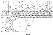
фиг.3 - частичный вид спереди средств для непрерывного гофрирования первого полотна;figure 3 is a partial front view of the means for continuously corrugating the first web;
фиг.4 - вид сверху выпускной части средств для непрерывного гофрирования первого полотна;4 is a top view of the outlet of the means for continuously corrugating the first web;
фиг.5 - вид в перспективе выпускной части средств для непрерывного гофрирования первого полотна;5 is a perspective view of the outlet of the means for continuously corrugating the first web;
фиг.6 - схематический вид другого варианта исполнения машины, на которой осуществляют наложение плоского полотна с обеих сторон;6 is a schematic view of another embodiment of a machine on which a flat web is applied on both sides;
фиг.7 - вид спереди других средств для приведения в действие нижних стержней;7 is a front view of other means for actuating the lower rods;
фиг.8 - схематический вид снизу средств для приведения в действие нижних стержней при введении их между полотнами;Fig. 8 is a schematic bottom view of the means for actuating the lower rods when inserted between the webs;
фиг.9 и 10 - виды двух различных возможных вариантов сопряжения между верхним конвейером и нижним конвейером для выполнения различных видов гофрирования;Fig.9 and 10 are views of two different possible pairing between the upper conveyor and the lower conveyor to perform various types of corrugation;
фиг.11-19 - виды дополнительных возможных вариантов исполнения различных типов гофрированных листообразных элементов.11-19 - types of additional possible embodiments of various types of corrugated sheet-like elements.
Предпочтительные варианты осуществления изобретенияPreferred Embodiments
Автоматическая машина (см. чертежи) для изготовления гофрированных листообразных элементов, в частности, для упаковки, теплоизоляции, звукоизоляции и т.п. содержит: остов, обозначенный в общем позицией 1, на котором установлены средства, обозначенные в общем позицией 2, для непрерывного гофрирования первого полотна.An automatic machine (see drawings) for the manufacture of corrugated sheet-like elements, in particular for packaging, thermal insulation, sound insulation, etc. contains: a skeleton, indicated generally by 1, on which are installed means, indicated by a general position 2, for continuously corrugating the first web.
Упомянутые средства для непрерывного гофрирования первого полотна представлены в виде катушки 5 для подачи первого полотна 3, установленной с возможностью вращения на остове 1 и подачи полотна, предпочтительно изготовленного из вспененного пластикового материала.Said means for continuously corrugating the first web are presented in the form of a
Можно также подавать первое полотно и по меньшей мере одно первое смежное полотно так, чтобы была продольная линия раздела между полотнами 3, которые подвергают гофрированию.It is also possible to feed the first web and at least one first adjacent web so that there is a longitudinal dividing line between the
Гофрирующие средства 2 представлены в виде верхнего конвейера, обозначенного в общем позицией 10, и нижнего конвейера 11.The corrugating means 2 are presented in the form of an upper conveyor, indicated generally by 10, and a
Верхний конвейер представлен верхней цепью 12, которой сообщают непрерывное движение, и которая огибает звездочки 13, установленные по краям и связанные со средствами привода, с помощью которых задают вид движения и скорость перемещения полотна.The upper conveyor is represented by the upper chain 12, which reports continuous movement, and which bends around the
Верхний конвейер 10 содержит множество верхних стержней или планок, 14, присоединенных к боковым рычагам 15, выступающим от соединительных блоков 16, которые на практике сопряжены со звеньями цепи 12 так, чтобы они (рычаги) всегда располагались по существу под прямыми углами к направлению цепи.The
Верхние стержни 14 сопрягают с верхней поверхностью первого полотна 3 и перемещают в продольном направлении согласованно с нижним конвейером 11, содержащим нижнюю цепь 20, огибающую звездочки 21, которую приводят в движение так, чтобы обеспечивать синхронное движение нижней цепи 20 и верхней цепи 12.The
Средства для приведения в действие нижних стержней 24 присоединены к цепи 20 и представлены, например, в виде множества нижних цилиндров 23, расположенных под прямыми углами к протяжению цепи 20, с помощью которых поддерживают множество нижних стержней 24, перемещаемых вдоль направлений, по существу параллельных направлению верхних стержней 14 для введения их между упомянутыми стержнями.Means for actuating the
Более подробно, нижняя ветвь верхнего конвейера 10 на практике пересекает верхнюю ветвь нижнего конвейера 11 так, что верхние стержни 14 и нижние стержни 24 взаимно чередуются, и их попеременно сопрягают с противоположными сторонами первого полотна 3, которое соответственно принимает волнообразную форму, например, синусоидальную форму.In more detail, the lower branch of the
Нижним стержням 24 сообщают движение, перпендикулярное направлению движения полотна по причинам, более подробно описанным ниже, и для того, чтобы можно было выводить их из сопряжения с первым полотном, когда это требуется.The
Машина дополнительно содержит вспомогательную цепь 25, перемещаемую синхронно с цепью 20 и расположенную сбоку от верхнего конвейера, напротив стороны, где находятся цилиндры 23.The machine additionally contains an
Вспомогательной цепью поддерживают множество направляющих элементов 26, которые перемещают согласованно с цилиндрами 23 для того, чтобы с их помощью поддерживать свободные концы нижних стержней 24 в выведенном положении.The auxiliary chain supports a plurality of
Автоматическая машина дополнительно содержит средства 29 для подачи второго плоского полотна согласованно с первым полотном.The automatic machine further comprises means 29 for supplying a second flat web in coordination with the first web.
Упомянутые средства для подачи представлены в виде катушки 29 для подачи второго полотна 30, установленного на остове 1, причем полотно 30 подают на соединительный вал 31, расположенный под верхними стержнями, вблизи с верхней ветвью первого конвейера.Said feeding means are presented in the form of a
С помощью этого устройства второе полотно 30 располагают сбоку рядом с нижней поверхностью первого полотна 3, которому уже придана гофрированная конфигурация так, что некоторое количество нижних стержней 24 остается введенным в полости, образованные между первым полотном 3 и вторым полотном 30.With this device, the
Кроме того, машина содержит соединительные средства, с помощью которых обеспечивают взаимное соединение в дискретных областях между первым полотном 3 и вторым полотном 30.In addition, the machine contains connecting means by which they provide mutual connection in discrete areas between the
Упомянутые соединительные средства в предпочтительном варианте исполнения представлены в виде нагнетательных средств 40 для подачи горячего воздуха, с помощью которых на практике обеспечивают местное расплавление пластикового материала, представляющего собой первое и второе полотна, достигая соединения путем контакта в зоне вала 31, поверх которого пропускают второе полотно в контакте с нижними изгибами первого полотна.Said connecting means in a preferred embodiment are presented in the form of injection means 40 for supplying hot air, with the help of which, in practice, local plastic melting of the first and second webs is achieved, achieving connection by contact in the area of the
На этом этапе соединения с помощью верхних стержней 14 на практике первое полотно прижимают ко второму полотну, таким образом улучшая его присоединение ко второму плоскому полотну.At this stage, joining with the
Вблизи края верхней ветви нижнего конвейера 11 нижние стержни надлежит извлечь из полостей и таким образом вывести их из сопряжения с двумя соединенными полотнами, которые, как показано на фигурах, принимают конфигурацию, образующую множество полостей.Near the edge of the upper branch of the
Стержни 24 остаются в отведенном положении внутри соответствующих цилиндров 23 до тех пор, пока их не подводят к краю нижней ветви нижнего конвейера, где стержни выводят из цилиндров и располагают так, чтобы они находились под первым полотном и над вторым полотном.The
С помощью описанного выше устройства, таким образом, может быть получена машина, на которой можно непрерывно и автоматически соединять друг с другом два полотна из вспененного пластикового материала, одно из которых гофрируют так, чтобы сформировать между первым и вторым полотнами множество полостей, расположенных бок о бок, благодаря чему можно уменьшить массу получаемого изделия и образовать на практике множество камер, посредством которых создают действенный барьер, используемый как для звукоизоляции, так и для теплоизоляции.Using the device described above, in this way, a machine can be obtained on which it is possible to continuously and automatically connect to each other two sheets of foamed plastic material, one of which is corrugated so as to form between the first and second sheets many cavities located side by side side, due to which it is possible to reduce the mass of the obtained product and to form in practice many chambers, through which they create an effective barrier, used both for sound insulation and for thermal insulation.
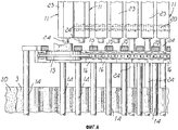
На фиг.6 представлен другой вариант исполнения машины, который, помимо аналогичных компонентов, описанных ранее, для соединения первого и второго полотен, содержит станцию 60 для присоединения дополнительного плоского полотна 61, естественно, с противоположной стороны от второго полотна 30.Figure 6 shows another embodiment of the machine, which, in addition to the similar components described earlier for connecting the first and second webs, contains a
С этой целью предусмотрено второе нагнетательное средство 62 для подачи горячего воздуха, с помощью которого производят местное расплавление дополнительного полотна 61 для обеспечения соединения гофрированного полотна 3 с соединительным полотном 63, расположенным над изготавливаемым изделием в направлении протяжения верхнего конвейера 10.For this purpose, a second injection means 62 for supplying hot air is provided, with the help of which local melting of the
Предпочтительно, чтобы на определенном протяжении стержни 24 оставались внутри изгибов для повышения стабильности размеров во время соединения и чтобы затем их извлекали для обеспечения возможности отделения путем извлечения стержней у края верхней ветви нижнего конвейера, которая в данном случае находится под верхним конвейером.It is preferable that the
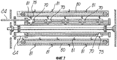
Предпочтительно предусмотрены другие средства для приведения в действие стержней 24 (см. фиг.7 и 8), причем такие средства представлены в виде кареток 70, которые можно перемещать в направлении, по существу параллельном продвижению стержней, причем каретки поддерживают с помощью двух направляющих балок 71, которые перемещают согласованно с нижним конвейером так, чтобы обеспечить возможность введения и извлечения стержней предусмотренным способом.Other means are preferably provided for actuating the rods 24 (see FIGS. 7 and 8), which means are provided in the form of
Для перемещения стержней 24 над каретками 70, снабженными пальцами 75 для сопряжения, предусмотрены конвейеры 80 для приведения в действие, снабженные упорами 81, установленными с равномерным шагом, которые перемещают в направлении движения стержней 24 и сопрягают последовательно с пальцами 75 так, чтобы обеспечить, с предназначенным шагом, поступательное движение стержней 24, которые принудительно вводят и извлекают из изгибов, образованных в полотне, подвергнутом гофрированию.To move the
С помощью описанного устройства можно обеспечить быстрое перемещение очень простыми средствами.Using the described device, it is possible to provide fast movement by very simple means.
Предпочтительно, чтобы упомянутые средства приведения в действие, или конвейеры, 80 были установлены у крайней части верхней ветви нижнего конвейера, где производят извлечение, и у нижней части нижней ветви нижнего конвейера, где осуществляют введение.Preferably, said actuation means, or conveyors, 80 are installed at the extreme part of the upper branch of the lower conveyor where the extraction is carried out, and at the lower part of the lower branch of the lower conveyor where the introduction is carried out.
С помощью машины можно также регулировать, при желании, ширину изгибов полотна, которое подвергают гофрированию, и для этого предусмотрены средства 90 для регулирования расстояния, с помощью которых можно изменять, при желании, расстояние между нижним конвейером 11 и верхним конвейером 10.Using the machine, you can also adjust, if desired, the bending width of the web, which is subjected to corrugation, and for this there are means 90 for adjusting the distance, with which you can change, if desired, the distance between the
Как показано на фиг.9 и 10, можно также изменять, при желании, расстояние между стержнями так, чтобы иметь возможность варьирования согласно требованиям производства как размеров изгибов, так и расстояния между изгибами, формируемыми в гофрируемом полотне 10.As shown in FIGS. 9 and 10, it is also possible to change, if desired, the distance between the rods so as to be able to vary according to the production requirements both the dimensions of the bends and the distance between the bends formed in the
Следует отметить, и это является очень важной особенностью изобретения, что с помощью машины, описанной выше, можно непрерывно изготавливать полотно, в котором гофрированный слой получают путем непрерывного волнообразного изгибания плоского полотна и формирования изгибов, располагаемых по существу под прямыми углами к направлению движения ленты; кроме того, изгибы присоединяют в дискретных областях по меньшей мере к одному другому плоскому полотну.It should be noted, and this is a very important feature of the invention, that using the machine described above, it is possible to continuously produce a web in which the corrugated layer is obtained by continuously waving bending the flat web and forming bends located essentially at right angles to the direction of movement of the tape; in addition, bends are attached in discrete areas to at least one other flat web.
Кроме того, благодаря возможности соединения множества полотен на последовательных этапах можно получать очень широкий диапазон совершенно разных изделий.In addition, due to the ability to connect multiple paintings at successive stages, you can get a very wide range of completely different products.
Из сказанного выше, таким образом, несомненно, следует, что благодаря изобретению достигнуты поставленные цели и задачи и, в частности, то, что с помощью машины, описанной выше, можно обеспечивать автоматически и непрерывно соединение двух или большего числа полотен вспененного пластикового материала, таким образом получая готовое изделие, которое с функциональной и коммерческой точек зрения является особенно практичным и полезным.From the foregoing, therefore, undoubtedly, it follows that thanks to the invention the goals and objectives are achieved and, in particular, that using the machine described above, it is possible to automatically and continuously connect two or more canvases of foamed plastic material, such in a way that produces a finished product that, from a functional and commercial point of view, is especially practical and useful.
Изобретение, представленное таким образом, может быть подвергнуто ряду модификаций, которые подпадают под объем прилагаемой формулы изобретения.The invention thus presented may be subjected to a number of modifications that fall within the scope of the appended claims.
Некоторые возможные варианты исполнения гофрированного листообразного элемента проиллюстрированы со ссылками на фиг.11-19; упомянутый элемент изготавливают путем использования устройства, описанного выше типа, которое может содержать дополнительные технологические станции, или в которое можно вводить уже изготовленный листообразный элемент вместо одного из полотен.Some possible embodiments of a corrugated sheet-like element are illustrated with reference to FIGS. 11-19; said element is made by using a device of the type described above, which may contain additional processing stations, or into which an already manufactured sheet-like element can be introduced instead of one of the webs.
На фиг.11 показан гофрированный элемент, обозначенный позицией 50, в который введен дополнительный гофрированный слой и соединен с плоским полотном, с одной стороны которого уже было сформировано гофрированное полотно.11 shows a corrugated element, indicated by 50, into which an additional corrugated layer is inserted and connected to a flat web, on one side of which a corrugated web has already been formed.
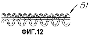
На фиг.12 представлен вид гофрированного листообразного элемента 51, в котором с противоположных сторон плоского полотна расположены гофрированные полотна с различными шагами гофр.On Fig presents a view of the corrugated sheet-
На фиг.13 представлен листообразный элемент 52, содержащий гофрированные компоненты, присоединенные к сторонам плоского полотна; один из упомянутых гофрированных компонентов имеет переменный шаг гофр, т.е. изгиб сформирован между пространствами, в которых, вместо изгиба, обеспечен контакт между плоским полотном и гофрированным полотном, а гофр имеет протяженность, соответствующую шагу промежутка, т.е. области, в которой гофр можно было сформировать.On Fig presents a sheet-
На фиг.14 представлен листообразный элемент 53, полученный из двух плоских полотен, между которыми расположено гофрированное полотно.On Fig presents a leaf-shaped
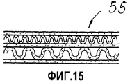
На фиг.15 представлен листообразный элемент 54, в котором в чередующемся порядке расположены гофрированные и плоские полотна; гофрированный элемент 55 на фиг.16 также содержит чередующиеся гофрированные и плоские полотна, причем гофрированные полотна сформированы с различными шагами между гофрами и различной шириной гофр.On Fig presents a leaf-shaped
На фиг.17 представлен листообразный элемент 56, полученный путем соединения плоского полотна с гофрированным полотном с чередующимся шагом;On Fig presents a leaf-shaped
на фиг.18 вместо этого показан листообразный элемент 57, в котором гофрированное полотно с чередующимся шагом расположено между двумя плоскими полотнами.Fig. 18 instead shows a sheet-
На фиг.19 представлен вид листообразного элемента 58, где плоские полотна, между которыми расположены гофрированные полотна различного типа, например гофрированное полотно с одинаковым шагом и гофрированное полотно с чередующимся шагом, уложены попеременно.On Fig presents a view of the leaf-shaped
Изделия, описанные выше, можно изготавливать путем введения дополнительных технологических станций на машине, описанной выше, или можно использовать машину того же типа, в которую можно подавать уже изготовленное изделие и получать новое изделие путем соединения множества ранее полученных полотен для получения выбранной композиции.The products described above can be manufactured by introducing additional process stations on the machine described above, or you can use the same type of machine into which you can feed an already manufactured product and get a new product by combining many previously obtained paintings to obtain the selected composition.
Все детали могут быть дополнительно заменены другими технически эквивалентными компонентами, и отдельные характеристики, приведенные для описания конкретных примеров, могут быть в действительности заменены другими, отличными от них характеристиками, которые представлены в других примерах вариантов исполнения.All parts can be further replaced by other technically equivalent components, and the individual characteristics given to describe specific examples can in fact be replaced by other, different from them characteristics, which are presented in other examples of embodiments.
На практике можно использовать любые материалы, а также любые возможные формы и размеры в зависимости от их конкурентноспособности при конкретных вариантах применения и в соответствии с предъявляемыми требованиями.In practice, you can use any materials, as well as any possible shapes and sizes, depending on their competitiveness in specific applications and in accordance with the requirements.
Приоритет формулы изобретения настоящей заявки испрашивается на основании Итальянской заявки на патент №М12003А000930.The priority of the claims of the present application is claimed on the basis of the Italian patent application No. M12003A000930.
Claims (24)
Applications Claiming Priority (2)
| Application Number | Priority Date | Filing Date | Title |
|---|---|---|---|
| IT000930A ITMI20030930A1 (en) | 2003-05-08 | 2003-05-08 | AUTOMATIC MACHINE FOR THE PRODUCTION OF CORRUGATED LASTRIFORM ELEMENTS PARTICULARLY FOR PACKAGING, THERMAL AND ACOUSTIC INSULATION AND SIMILAR |
| ITMI2003A000930 | 2003-05-08 |
Publications (2)
| Publication Number | Publication Date |
|---|---|
| RU2005134360A RU2005134360A (en) | 2006-04-27 |
| RU2363583C2 true RU2363583C2 (en) | 2009-08-10 |
Family
ID=33428312
Family Applications (1)
| Application Number | Title | Priority Date | Filing Date |
|---|---|---|---|
| RU2005134360/12A RU2363583C2 (en) | 2003-05-08 | 2004-04-23 | Automatic machine for manufacture of corrugated sheet-shaped elements, in particular for package, heat insulation, sound insulation, etc |
Country Status (14)
| Country | Link |
|---|---|
| US (1) | US8215363B2 (en) |
| EP (1) | EP1620253B9 (en) |
| JP (1) | JP4755583B2 (en) |
| KR (1) | KR101127557B1 (en) |
| CN (1) | CN1784299B (en) |
| AT (1) | ATE396863T1 (en) |
| CA (1) | CA2524618C (en) |
| DE (1) | DE602004014129D1 (en) |
| DK (1) | DK1620253T5 (en) |
| ES (1) | ES2308175T3 (en) |
| IT (1) | ITMI20030930A1 (en) |
| PL (1) | PL1620253T3 (en) |
| RU (1) | RU2363583C2 (en) |
| WO (1) | WO2004098867A1 (en) |
Families Citing this family (11)
| Publication number | Priority date | Publication date | Assignee | Title |
|---|---|---|---|---|
| FR2900419B1 (en) * | 2006-04-26 | 2009-02-13 | Schlumberger Sa N | METHOD OF MANUFACTURING NON-WOVEN FABRIC IN THREE DIMENSIONS, MANUFACTURING LINE FOR CARRYING OUT SAID METHOD, AND NON-WOVEN PRODUCT IN THREE DIMENSIONS OBTAINED |
| DE102008048981A1 (en) | 2008-09-25 | 2010-04-15 | Lts Lohmann Therapie-Systeme Ag | Injector and two-chamber system with sterile components |
| ITMI20121072A1 (en) * | 2012-06-20 | 2013-12-21 | Luigi Pecis | MACHINE FOR THE REALIZATION OF WAVY ELABORATED ELEMENTS. |
| ITMI20130271A1 (en) * | 2013-02-26 | 2014-08-27 | Interwave S R L | AUTOMATIC MACHINE FOR THE REALIZATION OF WAVELED SPLIT ELEMENTS. |
| DE102014206083A1 (en) * | 2014-03-31 | 2015-10-01 | Foldcore Gmbh | Method for forming a flat sheet material and device |
| EP3129219B1 (en) | 2014-04-08 | 2020-04-22 | Grifal S.p.A. | Automatic machine for providing corrugated sheet-like elements |
| DK3253569T3 (en) | 2015-02-04 | 2019-09-23 | Grifal S P A | Automatic machine for providing wavy plate-like elements |
| CN106077357B (en) * | 2016-05-24 | 2018-01-30 | 张茂忠 | A kind of streamline steel bar meter machine |
| DE102017205147B4 (en) * | 2017-03-27 | 2019-04-04 | Continental Automotive Gmbh | Process for producing a honeycomb body |
| CN111421900B (en) * | 2020-03-31 | 2021-07-20 | 泰州市源鑫包装有限公司 | Corrugated board manufacturing and processing technology |
| CN112026277A (en) * | 2020-09-06 | 2020-12-04 | 宁夏成峰包装印刷有限公司 | Crawler belt type pressing and pasting equipment for producing large-size staggered double corrugated paperboard core layers |
Family Cites Families (25)
| Publication number | Priority date | Publication date | Assignee | Title |
|---|---|---|---|---|
| US545354A (en) * | 1895-08-27 | Machine for corrugating and facing paper | ||
| CH37095A (en) | 1906-05-23 | 1907-04-30 | Hermann Brunner | Brick cutting machine |
| DE556985C (en) | 1931-06-06 | 1932-08-17 | Cartonnagenindustrie Ag F | Machine for making corrugated cardboard |
| US2166749A (en) | 1937-12-22 | 1939-07-18 | Harold G Burrill | Machine for undulatingly corrugating cardboard |
| US2764193A (en) * | 1954-01-11 | 1956-09-25 | Coruply Corp | Endless web corrugating machine |
| DE1561516A1 (en) | 1957-07-11 | 1970-05-06 | Trossinger Kartonagenfabrik Mi | Machine for the production of corrugated cardboard |
| US2926720A (en) * | 1957-08-02 | 1960-03-01 | Gosman Clarence Berveir | Method of and apparatus for making inflatable articles |
| US3157551A (en) * | 1957-09-17 | 1964-11-17 | Granozio Eurico | Apparatus for producing asymmetrically corrugated strips of cardboard, and the like |
| NL300043A (en) | 1963-10-31 | |||
| AT283889B (en) * | 1966-06-20 | 1970-08-25 | Palson Corp Ab | Method and device for the manufacture of corrugated cardboard |
| US3929536A (en) * | 1972-05-10 | 1975-12-30 | Westvaco Corp | Moisture resistant corner post |
| DE2227824C3 (en) * | 1972-06-08 | 1978-06-01 | Elda Ag, Glarus (Schweiz) | Cardboard machine for the production of cardboard sheets with a device for generating waves when wet |
| US3904473A (en) | 1973-08-29 | 1975-09-09 | Gte Sylvania Inc | Apparatus for producing a bilayered green ceramic tape |
| JPS5328017B2 (en) * | 1973-09-18 | 1978-08-11 | ||
| US4356051A (en) * | 1978-01-23 | 1982-10-26 | General Electric Company | Apparatus for making connection insulators |
| US4262390A (en) | 1979-05-21 | 1981-04-21 | Lummus Industries, Inc. | Roller gin and feed system incorporating the same |
| US4264390A (en) * | 1979-09-17 | 1981-04-28 | General Motors Corporation | Method and apparatus for making pipe sections in materials |
| JPS603983B2 (en) * | 1981-10-20 | 1985-01-31 | レンゴ−株式会社 | Partition plate forming equipment |
| US4874457A (en) * | 1988-04-21 | 1989-10-17 | Mcneil-Pc, Inc. | Web corrugating apparatus |
| CA2013028C (en) * | 1989-03-28 | 2000-04-11 | Tower Technologies (Proprietary) Limited | Method of making a rigid structure |
| US5753343A (en) | 1992-08-04 | 1998-05-19 | Minnesota Mining And Manufacturing Company | Corrugated nonwoven webs of polymeric microfiber |
| US5951816A (en) * | 1996-03-26 | 1999-09-14 | Marquip, Inc. | Single facer with small intermediate corrugating roll |
| CN2256371Y (en) * | 1996-08-01 | 1997-06-18 | 吴光雄 | Binding device for single face corrugate paper forming manufacturing machine |
| FR2755640B1 (en) * | 1996-11-12 | 1999-01-29 | Onduline Sa | INVERTER MACHINE |
| JPH11170408A (en) * | 1997-12-17 | 1999-06-29 | Ueno Hiroshi | Method for laminating corrugated fiberboard and laminating device |
-
2003
- 2003-05-08 IT IT000930A patent/ITMI20030930A1/en unknown
-
2004
- 2004-04-23 US US10/554,643 patent/US8215363B2/en not_active Expired - Fee Related
- 2004-04-23 PL PL04729058T patent/PL1620253T3/en unknown
- 2004-04-23 DK DK04729058T patent/DK1620253T5/en active
- 2004-04-23 ES ES04729058T patent/ES2308175T3/en not_active Expired - Lifetime
- 2004-04-23 CN CN2004800119123A patent/CN1784299B/en not_active Expired - Fee Related
- 2004-04-23 CA CA2524618A patent/CA2524618C/en not_active Expired - Lifetime
- 2004-04-23 KR KR1020057021236A patent/KR101127557B1/en not_active IP Right Cessation
- 2004-04-23 JP JP2006505241A patent/JP4755583B2/en not_active Expired - Fee Related
- 2004-04-23 DE DE602004014129T patent/DE602004014129D1/en not_active Expired - Lifetime
- 2004-04-23 WO PCT/EP2004/004331 patent/WO2004098867A1/en active Application Filing
- 2004-04-23 AT AT04729058T patent/ATE396863T1/en active
- 2004-04-23 RU RU2005134360/12A patent/RU2363583C2/en not_active IP Right Cessation
- 2004-04-23 EP EP04729058A patent/EP1620253B9/en not_active Expired - Lifetime
Also Published As
| Publication number | Publication date |
|---|---|
| JP4755583B2 (en) | 2011-08-24 |
| ITMI20030930A1 (en) | 2004-11-09 |
| JP2006525142A (en) | 2006-11-09 |
| DK1620253T5 (en) | 2009-04-20 |
| DK1620253T3 (en) | 2008-12-08 |
| PL1620253T3 (en) | 2008-10-31 |
| EP1620253B1 (en) | 2008-05-28 |
| CA2524618C (en) | 2012-06-05 |
| KR101127557B1 (en) | 2012-03-27 |
| EP1620253B9 (en) | 2009-03-18 |
| ATE396863T1 (en) | 2008-06-15 |
| KR20060014046A (en) | 2006-02-14 |
| DE602004014129D1 (en) | 2008-07-10 |
| US20100024967A1 (en) | 2010-02-04 |
| EP1620253A1 (en) | 2006-02-01 |
| CN1784299A (en) | 2006-06-07 |
| WO2004098867A1 (en) | 2004-11-18 |
| ES2308175T3 (en) | 2008-12-01 |
| RU2005134360A (en) | 2006-04-27 |
| CA2524618A1 (en) | 2004-11-18 |
| CN1784299B (en) | 2012-04-04 |
| US8215363B2 (en) | 2012-07-10 |
Similar Documents
| Publication | Publication Date | Title |
|---|---|---|
| RU2363583C2 (en) | Automatic machine for manufacture of corrugated sheet-shaped elements, in particular for package, heat insulation, sound insulation, etc | |
| US3902710A (en) | Accordion, folding and cutting apparatus | |
| US7832446B2 (en) | Method and device for manufacturing a composite web on the basis of at least two webs | |
| US7459049B2 (en) | Method and apparatus for manufacturing open core elements from web material | |
| US7024736B2 (en) | Apparatus and method for manufacture of multilayer metal products | |
| TW201022522A (en) | Waste-free method of making window treatments | |
| US6254523B1 (en) | Method of imparting directional permanency of folding to sheet, and apparatus therefor | |
| KR20160138286A (en) | Method for shaping a flat web material, and device | |
| US7695267B2 (en) | Rib forming apparatus and method | |
| EP3253569B1 (en) | Automatic machine for providing corrugated sheet-like elements | |
| KR880000659A (en) | Method and apparatus for forming expanded mesh material | |
| US3819453A (en) | Apparatus for corrugating a web of thin material such as paper, in a continuous process | |
| KR20010090926A (en) | double bellows formation apparatus for straw | |
| NL192518C (en) | Device for manufacturing a foldable sheet. | |
| KR100988638B1 (en) | Device for manufacturing tape flag | |
| CN216953956U (en) | Woven bag drying machine | |
| KR20180024077A (en) | The mold to diagonal flow type corrugate and manufacturing method for total heat exchanger using same | |
| JPS6258798B2 (en) | ||
| JPH0729651B2 (en) | Foldable flexible partition manufacturing method | |
| JPH1110250A (en) | Production device for expanded metal | |
| EP1055611A2 (en) | Composite film for packages, and apparatus for the production thereof | |
| GB2387343A (en) | Method for manufacture of multilayer metal products | |
| JPH0576422B2 (en) | ||
| WO2014191418A1 (en) | Method and apparatus for simultaneous and continuous foaming of two or more panels | |
| JPH04232042A (en) | Manufacture of honeycomb core |
Legal Events
| Date | Code | Title | Description |
|---|---|---|---|
| MM4A | The patent is invalid due to non-payment of fees |
Effective date: 20160424 |