EP4438520A1 - Beverage container, and method for assembling beverage container - Google Patents
Beverage container, and method for assembling beverage container Download PDFInfo
- Publication number
- EP4438520A1 EP4438520A1 EP22898165.0A EP22898165A EP4438520A1 EP 4438520 A1 EP4438520 A1 EP 4438520A1 EP 22898165 A EP22898165 A EP 22898165A EP 4438520 A1 EP4438520 A1 EP 4438520A1
- Authority
- EP
- European Patent Office
- Prior art keywords
- beverage
- extraction pipe
- beverage extraction
- container
- sealing member
- Prior art date
- Legal status (The legal status is an assumption and is not a legal conclusion. Google has not performed a legal analysis and makes no representation as to the accuracy of the status listed.)
- Pending
Links
Images








Classifications
-
- B—PERFORMING OPERATIONS; TRANSPORTING
- B65—CONVEYING; PACKING; STORING; HANDLING THIN OR FILAMENTARY MATERIAL
- B65D—CONTAINERS FOR STORAGE OR TRANSPORT OF ARTICLES OR MATERIALS, e.g. BAGS, BARRELS, BOTTLES, BOXES, CANS, CARTONS, CRATES, DRUMS, JARS, TANKS, HOPPERS, FORWARDING CONTAINERS; ACCESSORIES, CLOSURES, OR FITTINGS THEREFOR; PACKAGING ELEMENTS; PACKAGES
- B65D77/00—Packages formed by enclosing articles or materials in preformed containers, e.g. boxes, cartons, sacks or bags
- B65D77/04—Articles or materials enclosed in two or more containers disposed one within another
- B65D77/06—Liquids or semi-liquids or other materials or articles enclosed in flexible containers disposed within rigid containers
-
- B—PERFORMING OPERATIONS; TRANSPORTING
- B65—CONVEYING; PACKING; STORING; HANDLING THIN OR FILAMENTARY MATERIAL
- B65D—CONTAINERS FOR STORAGE OR TRANSPORT OF ARTICLES OR MATERIALS, e.g. BAGS, BARRELS, BOTTLES, BOXES, CANS, CARTONS, CRATES, DRUMS, JARS, TANKS, HOPPERS, FORWARDING CONTAINERS; ACCESSORIES, CLOSURES, OR FITTINGS THEREFOR; PACKAGING ELEMENTS; PACKAGES
- B65D85/00—Containers, packaging elements or packages, specially adapted for particular articles or materials
- B65D85/70—Containers, packaging elements or packages, specially adapted for particular articles or materials for materials not otherwise provided for
- B65D85/72—Containers, packaging elements or packages, specially adapted for particular articles or materials for materials not otherwise provided for for edible or potable liquids, semiliquids, or plastic or pasty materials
-
- B—PERFORMING OPERATIONS; TRANSPORTING
- B67—OPENING, CLOSING OR CLEANING BOTTLES, JARS OR SIMILAR CONTAINERS; LIQUID HANDLING
- B67D—DISPENSING, DELIVERING OR TRANSFERRING LIQUIDS, NOT OTHERWISE PROVIDED FOR
- B67D1/00—Apparatus or devices for dispensing beverages on draught
- B67D1/04—Apparatus utilising compressed air or other gas acting directly or indirectly on beverages in storage containers
- B67D1/0462—Squeezing collapsible or flexible beverage containers, e.g. bag-in-box containers
-
- B—PERFORMING OPERATIONS; TRANSPORTING
- B67—OPENING, CLOSING OR CLEANING BOTTLES, JARS OR SIMILAR CONTAINERS; LIQUID HANDLING
- B67D—DISPENSING, DELIVERING OR TRANSFERRING LIQUIDS, NOT OTHERWISE PROVIDED FOR
- B67D1/00—Apparatus or devices for dispensing beverages on draught
- B67D1/08—Details
- B67D1/0801—Details of beverage containers, e.g. casks, kegs
- B67D1/0802—Dip tubes
-
- B—PERFORMING OPERATIONS; TRANSPORTING
- B67—OPENING, CLOSING OR CLEANING BOTTLES, JARS OR SIMILAR CONTAINERS; LIQUID HANDLING
- B67D—DISPENSING, DELIVERING OR TRANSFERRING LIQUIDS, NOT OTHERWISE PROVIDED FOR
- B67D1/00—Apparatus or devices for dispensing beverages on draught
- B67D1/08—Details
- B67D1/0829—Keg connection means
-
- B—PERFORMING OPERATIONS; TRANSPORTING
- B67—OPENING, CLOSING OR CLEANING BOTTLES, JARS OR SIMILAR CONTAINERS; LIQUID HANDLING
- B67D—DISPENSING, DELIVERING OR TRANSFERRING LIQUIDS, NOT OTHERWISE PROVIDED FOR
- B67D1/00—Apparatus or devices for dispensing beverages on draught
- B67D1/08—Details
- B67D1/0829—Keg connection means
- B67D1/0831—Keg connection means combined with valves
- B67D1/0832—Keg connection means combined with valves with two valves disposed concentrically
-
- B—PERFORMING OPERATIONS; TRANSPORTING
- B67—OPENING, CLOSING OR CLEANING BOTTLES, JARS OR SIMILAR CONTAINERS; LIQUID HANDLING
- B67D—DISPENSING, DELIVERING OR TRANSFERRING LIQUIDS, NOT OTHERWISE PROVIDED FOR
- B67D1/00—Apparatus or devices for dispensing beverages on draught
- B67D1/08—Details
- B67D1/0801—Details of beverage containers, e.g. casks, kegs
- B67D2001/0822—Pressurised rigid containers, e.g. kegs, figals
- B67D2001/0824—Pressurised rigid containers, e.g. kegs, figals with dip tubes
Definitions
- the present invention relates to a beverage container and a method of assembling a beverage container.
- a beverage container having a rigid outer container and a flexible inner container is known.
- Patent Literature 1 discloses a container containing a storage bag.
- the container described in Patent Literature 1 includes an outer container (5) having an opening (22), a storage bag (1) accommodated in the outer container (5) and having a spout (4), and a lid portion (8) connected to both the storage bag and the outer container.
- Patent Literature 1 it is described that the hole portion of the spout (4) and the hole portion of the lid portion (8) are fitted, and that the spout (4) and the pouring nozzle (6) are connected.
- Patent Literature 2 discloses a flexible container produced from a film material.
- the flexible container described in Patent Literature 2 includes a cap (5) attached to a neck of a rigid outer container (2), a fixing lip (4) forming a part of the cap (5), a bag (3) that is fixed to the fixing lip (4), a shut-off valve (10) that can be pushed downward, and a dispenser tube (8).
- Patent Literature 3 discloses a beverage supply device.
- the beverage supply device described in Patent Literature 3 includes a container body (20) including a neck part (22), a flexible bag body (90) arranged inside the container body (20), a cap (30), and a cylinder body (50) .
- An object of the present invention is to provide a technique for facilitating the assembly of a beverage container including an outer container, a fitting, and a replaceable component having a bag.
- a beverage container includes an outer container having a first mouth portion, a fitting having a beverage extraction pipe, and a replaceable component attached to the beverage extraction pipe and arranged in an inner space of the outer container.
- the fitting includes an attachment portion attached to the first mouth portion of the outer container, a second mouth portion connectable to a beverage filling nozzle or a dispense head, an annular portion extending outward from the second mouth portion and connecting the second mouth portion and the attachment portion, and the beverage extraction pipe extending toward a bottom of the outer container.
- the replaceable component includes a sealing member slidable along a longitudinal direction of the beverage extraction pipe and being in annular contact with an outer surface of the beverage extraction pipe at an installation position, a tubular body holding the sealing member and being supported by the beverage extraction pipe via the sealing member located at the installation position, and a bag for containing a beverage attached to the tubular body.
- a method of assembling a beverage container includes: preparing an outer container having a first mouth portion; preparing a fitting having an attachment portion attachable to the first mouth portion, a second mouth portion connectable to a beverage filling nozzle or a dispense head, an annular portion extending outward from the second mouth portion connecting the second mouth portion and the attachment portion, and a beverage extraction pipe; preparing a replaceable component having a sealing member, a tubular body holding the sealing member, and a bag for containing a beverage attached to the tubular body; attaching the replaceable component to the beverage extraction pipe; inserting the replaceable component and the beverage extraction pipe into the outer container; and attaching the attachment portion of the fitting to the first mouth portion of the outer container.
- the attaching the replaceable component to the beverage extraction pipe includes: sliding the sealing member and the tubular body along a longitudinal direction of the beverage extraction pipe; and making the sealing member into annular contact with an outer surface of the beverage extraction pipe at an installation position.
- the inserting the replaceable component and the beverage extraction pipe into the outer container includes: inserting a whole of the beverage extraction pipe, the sealing member, the tubular body supported by the beverage extraction pipe via the sealing member, and the bag attached to the tubular body into the outer container through the first mouth portion.
- a direction from a bottom portion 23 of an outer container 2 toward a first mouth portion 27 of the outer container 2 is defined as "upward” and a direction from the first mouth portion 27 to the bottom portion 23 is defined as “downward”. Therefore, regardless of whether the outer container 2 is in the upright posture or the inverted posture, the direction from the bottom portion 23 to the first mouth portion 27 is “upward”. Further, regarding a fitting 3 before being attached to the outer container 2, a direction from a lower end 45g of a beverage extraction pipe 45 toward an upper end 45e of the beverage extraction pipe 45 is defined as “upward”, and a direction from the upper end 45e toward the lower end 45g is defined as “downward”.
- a term “outward” means a direction away from a central axis C1 of a second mouth portion 34 of the fitting 3 (or a direction away from a central axis C2 of the beverage extraction pipe 45). Further, a term “inward” means a direction toward the central axis C1 of the second mouth portion 34 of the fitting 3 (or a direction toward the central axis C2 of the beverage extraction pipe 45).
- FIGs. 1 and 2 are schematic cross-sectional views schematically showing a beverage container 1A according to a first embodiment.
- Fig. 1 shows a state before the beverage container 1A is assembled
- Fig. 2 shows a state after the beverage container 1A is assembled.
- Fig. 3 is a schematic cross-sectional view schematically showing how a replaceable component 5 is attached to a beverage extraction pipe 45.
- Fig. 4 is a schematic cross-sectional view schematically showing a state after the replaceable component 5 is attached to the beverage extraction pipe 45.
- Fig. 5 is a schematic two-view schematically showing an example of a fitting 3.
- FIG. 5 A schematic plan view is shown on the upper side of Fig. 5 , and a schematic cross-sectional view is shown on the lower side of Fig 5 .
- Fig. 6 is a schematic cross-sectional view schematically showing the beverage container 1A according to a first modified example of the first embodiment.
- Fig. 7 is a schematic cross-sectional view schematically showing the beverage container 1A (an example in which the beverage container 1A includes a spacer member 63) according to the first embodiment.
- Fig. 8 is a schematic cross-sectional view schematically showing a part of the beverage container 1A according to the first embodiment.
- Fig. 9 is a schematic two-view schematically showing an example of the spacer member 63.
- a schematic plan view is shown on the upper side of Fig.
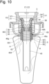
- Fig. 10 is a schematic cross-sectional view schematically showing a state after the replaceable component 5 is attached to the beverage extraction pipe 45.
- Fig. 11 is a schematic cross-sectional view schematically showing a part of the beverage container 1A according to the first embodiment.
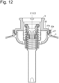
- Fig. 12 is a schematic cross-sectional view schematically showing a part of the beverage container 1A according to a second modified example of the first embodiment.
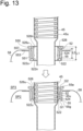
- Fig. 13 is a diagram for explaining each element of the replaceable component 5.
- Fig. 14 is a schematic two-view schematically showing an example of the replaceable component 5. A schematic plan view is shown on the upper side of Fig.
- Figs. 15 and 16 are schematic cross-sectional views schematically showing the beverage container 1A (an example in which the beverage container 1A includes a removal-preventing member 46) according to the first embodiment.
- Fig. 17 is a schematic cross-sectional view schematically showing a first modified example of the removal-preventing member 46.
- Fig. 18 is a schematic cross-sectional view schematically showing a second modified example of the removal-preventing member 46.
- a beverage container 1A includes an outer container 2, a fitting 3, and a replaceable component 5 including a bag 58.
- the outer container 2 defines an inner space SP1 in which the replaceable component 5 including the bag 58 is arranged.
- the outer container 2 has a container main body 22 and a first mouth portion 27. In an example shown in Fig. 1 , the first mouth portion 27 extends upward from the container main body 22.
- the outer container 2 is made of, for example, metal (more specifically, stainless steel). Alternatively, the outer container 2 may be made of resin.
- the fitting 3 is attached to the first mouth portion 27.
- the first mouth portion 27 has a first threaded portion 27s (more specifically, a male threaded portion).
- the first mouth portion 27 defines a first opening OP1 through which the replaceable component 5 can pass.
- the fitting 3 includes an attachment portion 32, a second mouth portion 34, an annular portion 36, and a beverage extraction pipe 45.
- a "fitting” means a member attached to the first mouth portion of the outer container and used for filling the bag with a beverage and / or taking out a beverage from the bag.
- the attachment portion 32 is attached to the first mouth portion 27 of the outer container 2.
- the attachment portion 32 has a second threaded portion 32s (more specifically, a female threaded portion) threadably engaging with the first threaded portion 27s of the first mouth portion 27.
- the attachment portion 32 is made of, for example, metal (more specifically, stainless steel). Alternatively, the attachment portion 32 may be made of resin.
- the second mouth portion 34 can be connected to a beverage filling nozzle or a dispense head.
- the second mouth portion 34 defines a second opening OP2 through which a tip portion of the beverage filling nozzle (or a tip portion of a plunger member of the dispense head) can pass.
- the second mouth portion 34 has an engaging portion 345 engageable with the dispense head.
- the second mouth portion 34 is made of, for example, metal (more specifically, stainless steel).
- the second mouth portion 34 may be made of resin.
- the annular portion 36 extends outward from the second mouth portion 34. (In other words, the annular portion 36 extends from the second mouth portion 34 in a direction away from a central axis C1 of the second mouth portion 34). Further, the annular portion 36 connects the second mouth portion 34 and the attachment portion 32. In the example shown in Fig. 1 , the annular portion 36 has an inner portion 36n connected to the second mouth portion 34 and an outer portion 36u connected to the attachment portion 32. In the example shown in Fig. 1 , an inner peripheral edge portion of the annular portion 36 is connected to the second mouth portion 34, and an outer peripheral edge portion of the annular portion 36 is connected to the attachment portion 32. An upper surface of the annular portion 36 may be a plane parallel to a horizontal plane or a plane inclined with respect to the horizontal plane.
- an inner diameter of the first mouth portion 27 of the outer container 2 can be remarkably larger than an inner diameter of the second mouth portion 34 of the fitting 3.
- the inner diameter of the first mouth portion 27 is large, it is easy to insert the replaceable component 5 having the bag 58 into the outer container 2 via the first mouth portion 27.
- the beverage extraction pipe 45 extends toward a bottom portion 23 of the outer container 2. Further, an upper end 45e of the beverage extraction pipe 45 is arranged in a vicinity of the second mouth portion 34.
- the beverage extraction pipe 45 has an inner surface 45n that defines a beverage flow channel Fl.
- the replaceable component 5 is attached to the beverage extraction pipe 45 and is arranged in the inner space SP1 of the outer container 2.
- a whole of the replaceable component 5 and a whole of the beverage extraction pipe 45 are arranged in the inner space SP1 of the outer container 2.
- the replaceable component 5 includes a sealing member 52, a tubular body 55, and the bag 58.
- the frequency of replacing the replaceable component 5 is higher than the frequency of replacing the outer container 2 and the fitting 3.
- the replaceable component 5 may be replaced every cycle.
- the replaceable component 5 may be a one-time use disposable component.
- the sealing member 52 is slidable along a longitudinal direction of the beverage extraction pipe 45. In this case, it is easy to move the sealing member 52 toward an installation position P (more specifically, an upper portion 452 of the beverage extraction pipe 45) on the beverage extraction pipe 45, and it is easy to arrange the sealing member 52 at the installation position P (more specifically, the upper portion 452 of the beverage extraction pipe 45) on the beverage extraction pipe 45.
- the sealing member 52 slides with respect to the beverage extraction pipe 45 in a state where an outer surface 45u of the beverage extraction pipe 45 and the sealing member 52 are in annular contact with each other.
- an appropriate frictional resistance is generated between the sealing member 52 and the beverage extraction pipe 45. Note that if the frictional resistance is too small, the sealing member 52 may be determined to be a defective product.
- the sealing member 52 is in annular contact with the outer surface 45u of the beverage extraction pipe 45 when it is located at the installation position P. This contact prevents fluid (in other words, the beverage or a gas) from leaking from between the sealing member 52 and the beverage extraction pipe 45.
- the sealing member 52 is made of an elastic material such as rubber.
- the tubular body 55 is arranged outside the sealing member 52 and holds the sealing member 52.
- the tubular body 55 prevents an outer diameter of the sealing member 52 from increasing. In this way, the sealing member 52 arranged between the tubular body 55 and the outer surface 45u of the beverage extraction pipe 45 is compressed, and the sealing effect of the sealing member 52 is improved.
- the tubular body 55 is supported by the beverage extraction pipe 45 via the sealing member 52 located at the installation position P.
- the bag 58 for accommodating the beverage is attached to the tubular body 55.
- the beverage contained in the bag 58 is, for example, an alcoholic beverage such as beer, or an effervescent beverage such as beer or non-alcoholic beer.
- the replaceable component 5 having the sealing member 52 is attached to the beverage extraction pipe 45. Therefore, it is easy to attach the replaceable component 5 to the beverage extraction pipe 45 (see Figs. 3 and 4 ).
- the replaceable component 5 having the bag 58 is attached to the beverage extraction pipe 45.
- the bag 58 can be compactly arranged around the beverage extraction pipe 45. Therefore, the replaceable component 5 having the bag 58 and the beverage extraction pipe 45 to which the replaceable component 5 is attached can be easily inserted into the outer container 2 (see Fig. 1 ).
- the fitting 3 has the annular portion 36. Due to the presence of the annular portion 36, the inner diameter of the first mouth portion 27 of the outer container 2 can be remarkably larger than the inner diameter of the second mouth portion 34 of the fitting 3. When the inner diameter of the first mouth portion 27 is large, it is easy to insert the replaceable component 5 having the bag 58 into the outer container 2 through the first mouth portion 27 (see Fig. 1 ).
- the beverage container 1A that is easy to assemble is provided.
- the outer container 2 is a rigid container (in other words, a container whose shape does not substantially change).
- the container main body 22 of the outer container 2 has the bottom portion 23 and a body portion 24.
- the container main body 22 may have an upper plate portion 25 that connects the body portion 24 and the first mouth portion 27.
- the upper plate portion 25 and the first mouth portion 27 are connected via a welded portion 26.
- the fitting 3 is an assemble body M1 including the attachment portion 32, the second mouth portion 34, the annular portion 36, and the beverage extraction pipe 45.
- the assemble body M1 may include a first valve member 37 described later, a first spring 38 described later, and a first spring receiver 39 described later. Further, the assemble body M1 may include a second valve member 41 described later, a second spring 42 described later, and a second spring receiver 454 described later.
- the fitting 3 assembled in the assemble body M1 is attached to the first mouth portion 27 of the outer container 2 so that the whole of the fitting 3 is attached to the outer container 2. In this case, it is not necessary to separately place each member constituting the fitting 3 to the outer container 2.
- the fitting 3 may be divided into a plurality of parts.
- the attachment portion 32 and a assemble body M2 of the fitting 3 excluding the outer portion 36u of the annular portion 36 are placed to the outer container 2, and then the attachment portion 32 constituting a part of the fitting 3 is attached to the outer container 2.
- the inner portion 36n of the annular portion 36 and the outer portion 36u of the annular portion 36 are separate bodies. Further, when the attachment portion 32 is attached to the first mouth portion 27 of the outer container 2, the inner portion 36n of the annular portion 36 and the outer portion 36u of the annular portion 36 are connected by pressing force.
- the beverage container 1A includes a spacer member 63 arranged between the annular portion 36 and the tubular body 55.
- the spacer member 63 prevents over-deformation (excessive-deformation) of the bag 58 toward the annular portion 36.
- the spacer member 63 is not attached to the tubular body 55.
- the tubular body 55 is movable relative to the spacer member 63.
- the spacer member 63 and the replaceable component 5 having the tubular body 55 can be handled separately.
- the frequency of replacing the spacer member 63 can be made lower than the frequency of replacing the replaceable component 5.
- the spacer member 63 is preferably a non-flexible member (in other words, a member whose substantial deformation is suppressed).
- the spacer member 63 may be made of resin, or may be made of metal such as stainless steel.
- the spacer member 63 prevents the bag 58 from coming into contact with an outer cylindrical portion 40 described later. In this case, damage to the bag 58 due to contact between the bag 58 and the outer cylindrical portion 40 (more specifically, a through hole portion 40h formed in the outer cylindrical portion 40) is prevented.
- the spacer member 63 has an upper end portion 63e located above a lower end 27g of the first mouth portion 27.
- the upper end portion 63e is arranged in the annular region AR1 between the first mouth portion 27 and the outer cylindrical portion 40.
- the upper end portion 63e of the spacer member 63 may be contactable to the annular portion 36 of the fitting 3.
- the spacer member 63 is arranged so as to surround the outer cylindrical portion 40, and a lower end of the spacer member 63 is located below a lower end of the outer cylindrical portion 40. In this case, the spacer member 63 can effectively prevent the bag 58 from coming into contact with the outer cylindrical portion 40 (more specifically, the through hole portion 40h) .
- the spacer member 63 has a lower end portion 63g extending inward toward the beverage extraction pipe 45.
- the lower end portion 63g of the spacer member 63 is located below the lower end 27g of the first mouth portion 27. It is preferable that the lower end portion 63g of the spacer member 63 is contactable to the tubular body 55 (more specifically, a first flange 553 of the tubular body 55) of the replaceable component 5.
- the spacer member 63 has a lower surface 63d which is arranged to face the bag 58.
- the lower surface 63d is preferably an inclined surface (more specifically, an inclined convex surface) whose height increases as a distance from the central axis C2 of the beverage extraction pipe 45 increases.
- the bag 58 is gently deformed along the lower surface 63d of the spacer member 63. As a result, over-deformation of the bag 58 is prevented, and damage to the bag 58 is prevented even more effectively.
- the spacer member 63 has a through hole portion 63h into which the beverage extraction pipe 45 is inserted.
- the through hole portion 63h may be able to receive an upper end portion of the tubular body 55 of the replaceable component 5.
- the tubular body 55 can move relative to the spacer member 63 in a vertical direction.
- the bag 58 may be damaged by an inner edge of the through hole portion 63h or an outer edge of the tubular body 55. Therefore, in the example shown in Fig. 8 , an inner diameter D1 of the through hole portion 63h of the spacer member 63 is set to a smaller value than a maximum outer diameter D2 of the tubular body 55 (more specifically, an outer diameter of the first flange 553).
- the first flange 553 of the tubular body 55 cannot move upward beyond the through hole portion 63h of the spacer member 63.
- the spacer member 63 is movable relative to the fitting 3.
- the spacer member 63 may be fixed to the fitting 3.
- the spacer member 63 may be fixed to the annular portion 36 of the fitting 3 by engagement (for example thread engagement) or welding.
- a recess portion 63f that allows the passage of gas is formed in the upper end portion 63e of the spacer member 63.
- the gas supplied from the outside of the outer container 2 can enter a space SP3 between the container main body 22 of the outer container 2 and the bag 58 through the recess portion 63f.
- an outer shell portion 633 of the spacer member 63 may be provided with a through hole portion that allows the passage of gas, apart from the above-mentioned through hole portion 63h.
- the spacer member 63 may have the outer shell portion 633 and reinforcing ribs 635 arranged inside the outer shell portion 633.
- the reinforcing ribs 635 reinforce the outer shell portion 633 and suppress the deformation of the outer shell portion 633.
- the fitting 3 has a first valve seat portion 341 and the first valve member 37.
- a gas valve V1 is constituted by the first valve seat portion 341 and the first valve member 37.
- the gas valve V1 is a valve whose state can be changed between an open state that allows the passage of gas and a closed state that prohibits the passage of gas.
- the first valve seat portion 341 is formed in the second mouth portion 34. More specifically, a part of an inner peripheral surface of the second mouth portion 34 functions as the first valve seat portion 341.
- the first valve seat portion 341 is constituted by, for example, an inclined surface whose inner diameter increases in a downward direction.
- the first valve member 37 is contactable to the first valve seat portion 341 and is separable from the first valve seat portion 341.
- a state in which the first valve member 37 is in contact with the first valve seat portion 341 corresponds to the closed state of the gas valve V1
- a state in which the first valve member 37 is separated from the first valve seat portion 341 corresponds to the open state of the gas valve V1.
- the fitting 3 is provided with the gas valve V1.
- the container main body 22 of the outer container 2 may be provided with the gas valve, and the fitting 3 may be provided with only a beverage valve.
- the first valve seat portion 341 formed in the second mouth portion 34 may function as a valve seat portion of the beverage valve, and the first valve member 37 may function as a valve body of the beverage valve.
- the sealing member 52 is attached to the beverage extraction pipe 45 at a position below the first valve member 37. In this case, an interference between the first valve member 37 and members arranged in the vicinity of the first valve member 37, and the replaceable component 5 including the sealing member 52 is prevented or suppressed. In the example shown in Fig. 10 , the sealing member 52 is arranged vertically below the first valve member 37.
- both the first valve member 37 and the sealing member 52 are attached to the beverage extraction pipe 45. More specifically, the first valve member 37 is attached to an upper end portion of the beverage extraction pipe 45, and the sealing member 52 is attached to the outer surface 45u (in other words, the outer peripheral surface) of the beverage extraction pipe 45. In this case, when the first valve member 37 moves downward so as to be separated from the first valve seat portion 341, the beverage extraction pipe 45 and the sealing member 52 move downward together with the first valve member 37.
- the fitting 3 includes the first spring 38 and the first spring receiver 39 in addition to the first valve member 37.
- the fitting 3 may include the outer cylindrical portion 40.
- the first spring 38 is arranged below the first valve member 37 and biases the first valve member 37 upward.
- the gas valve V1 is maintained in the closed state by a biasing force of the first spring 38.
- the gas valve V1 is opened when the first valve member 37 is pushed downward against the biasing force of the first spring 38.
- the first spring 38 is arranged outside the beverage extraction pipe 45 so as to surround the beverage extraction pipe 45.
- the first spring receiver 39 is arranged below the first spring 38 and supports the first spring 38. In the example shown in Fig. 10 , the first spring receiver 39 is arranged outside the beverage extraction pipe 45 so as to surround the beverage extraction pipe 45.
- the outer cylindrical portion 40 is arranged outside the beverage extraction pipe 45. It is preferable that the outer cylindrical portion 40 is provided with a plurality of through hole portions 40h that allow the passage of gas.
- the first spring 38 is arranged between the outer cylindrical portion 40 and the beverage extraction pipe 45. In this case, the first spring 38 is protected by the outer cylindrical portion 40.
- An upper end portion of the outer cylindrical portion 40 is fixed (more specifically, welded) to the second mouth portion 34 or the annular portion 36.
- a lower end portion 40g of the outer cylindrical portion 40 supports the first spring receiver 39.
- the lower end portion 40g of the outer cylindrical portion 40 may function as the first spring receiver 39.
- the tubular body 55 of the replaceable component 5 is arranged vertically below a structure M3 including the first spring 38, the first spring receiver 39, and the outer cylindrical portion 40 that protects the first spring 38.
- the tubular body 55 and the bag 58 before being filled with the beverage can be compactly arranged around the beverage extraction pipe 45 by utilizing a region vertically below the structure M3. Therefore, the replaceable component 5 having the tubular body 55 and the bag 58 can be easily inserted into the outer container 2 via the first mouth portion 27. In this way, the beverage container 1A can be easily assembled.
- a tubular portion 551 of the tubular body 55 and the sealing member 52 are arranged in a space inside a virtual cylinder (see the virtual cylinder indicated by a dashed line A) which is formed by virtually extending an outer edge of the outer cylindrical portion 40 downward.
- the fitting 3 may have a second valve seat portion 371 and the second valve member 41.
- a beverage valve V2 is constituted by the second valve seat portion 371 and the second valve member 41.
- the beverage valve V2 is a valve whose state can be changed between an open state that allows the passage of the beverage and a closed state that prohibits the passage of the beverage.
- the second valve seat portion 371 is formed in the first valve member 37. More specifically, an inner peripheral surface of a lower end portion of the first valve member 37 functions as the second valve seat portion 371.
- the second valve seat portion 371 is constituted by, for example, an inclined surface whose inner diameter increases in a downward direction.
- the second valve member 41 is contactable to the second valve seat portion 371 and is separable from the second valve seat portion 371.
- a state in which the second valve member 41 is in contact with the second valve seat portion 371 corresponds to the closed state of the beverage valve V2
- a state in which the second valve member 41 is separated from the second valve seat portion 371 corresponds to the open state of the beverage valve V2.
- the second valve member 41 is arranged inside the beverage extraction pipe 45. Further, the second valve member 41 can move in the vertical direction in the internal space of the beverage extraction pipe 45.
- the fitting 3 includes the second spring 42 and the second spring receiver 454 in addition to the second valve member 41.
- the second spring 42 is arranged below the second valve member 41 and biases the second valve member 41 upward.
- the beverage valve V2 is maintained in the closed state by a biasing force of the second spring 42.
- the beverage valve V2 is opened when the second valve member 41 is pushed downward against the biasing force of the second spring 42.
- the second spring 42 is arranged inside the beverage extraction pipe 45.
- the second spring receiver 454 is arranged below the second spring 42 and supports the second spring 42.
- the second spring receiver 454 is constituted by a stepped portion (in other words, a portion where an inner diameter changes) of the beverage extraction pipe 45.
- the sealing member 52 of the replaceable component 5 is arranged below the second valve member 41 and above the second spring receiver 454.
- the second mouth portion 34 of the fitting 3 is preferably arranged above the first mouth portion 27 of the outer container 2.
- the second mouth portion 34 of the fitting 3 is arranged so as to extend upward from the annular portion 36, and the attachment portion 32 of the fitting 3 is arranged so as to extend downward from the annular portion 36. In this way, the second mouth portion 34 is arranged above the first mouth portion 27 to which the attachment portion 32 is attached.
- the first valve member 37 that contacts the first valve seat portion 341 of the second mouth portion 34 can be arranged at a higher position.
- an upper end surface of the first valve member 37 is arranged at a position higher than the lower end 27g of the first mouth portion 27.
- the upper end surface of the first valve member 37 is arranged at a position higher than an upper surface 27e of the first mouth portion 27.
- the sealing member 52 and the tubular body 55 arranged below the first valve member 37 can be arranged at a higher position. Further, when the tubular body 55 is arranged at a high position, a height difference H1 between the lower end 27g of the first mouth portion 27 and a attaching position of the bag 58 to the tubular body 55 is reduced. Due to the reduction in the height difference H1, the bag 58 is prevented from being greatly deformed upward due to the increase of the internal pressure of the bag 58.
- an inner diameter D3 of the first mouth portion 27 is remarkably larger than an inner diameter D4 of the annular portion 36.
- the inner diameter D3 of the first mouth portion 27 is, for example, 6 cm or more and 12 cm or less, or 7 cm or more and 10 cm or less.
- the inner diameter D3 of the first mouth portion 27 is preferably at least 1.5 times larger, or at least 1.8 times larger than the inner diameter D4 of the annular portion 36.
- the inner diameter D3 of the first mouth portion 27 is sufficiently larger than the maximum outer diameter D2 of the tubular body 55 (more specifically, the outer diameter of the first flange 553).
- the difference between the inner diameter D3 of the first mouth portion 27 and the maximum outer diameter D2 of the tubular body 55 (more specifically, the outer diameter of the first flange 553) is, for example, 15 mm or more, 20 mm or more, or 25 mm or more.
- the maximum outer diameter D2 of the tubular body 55 is larger than the inner diameter D4 of the annular portion 36 and smaller than the inner diameter D3 of the first mouth portion 27.
- the first threaded portion 27s of the first mouth portion 27 of the outer container 2 is a male threaded portion. Since the first threaded portion 27s is a male threaded portion (in other words, an external threaded portion), an inner surface 27n of the first mouth portion 27 can be made smooth. In a case in which the inner surface 27n of the first mouth portion 27 is a smooth surface, the bag 58 is less likely to get caught on the inner surface 27n of the first mouth portion 27, when the replaceable component 5 having the bag 58 is inserted into the outer container 2 through the first mouth portion 27. In this way, the beverage container 1A is easily assembled.
- first threaded portion 27s of the first mouth portion 27 of the outer container 2 may be a female threaded portion
- the second threaded portion 32s of the attachment portion 32 of the fitting 3 may be a male threaded portion
- a lower end surface of the first mouth portion 27 may be an inclined surface 27t whose inner diameter decreases in an upward direction.
- the inclined surface 27t may be a tapered surface or an R surface (in other words, a convex arcuate surface). Since the lower end surface of the first mouth portion 27 is an inclined surface 27t whose inner diameter decreases in an upward direction, the bag 58 is smoothly reduced in diameter by the inclined surface 27t when the replaceable component 5 is taken out of the outer container 2. In this way, the bag 58 which is bulky can be smoothly removed from the outer container 2 through the first mouth portion 27.
- the second mouth portion 34 of the fitting 3 has a recess portion 347 capable of receiving a lower end of a dispense head main body 80 (see Fig. 25 if necessary).
- the second mouth portion 34 may have a shoulder portion 348 that positions the lower end of the dispense head main body 80. Further, the second mouth portion 34 may have an annular outward protruding portion 349 at the upper end.
- the beverage container 1A includes a sealing ring 65 arranged between the first mouth portion 27 and the annular portion 36.
- the sealing ring 65 prevents gas from leaking out from a gap between the outer container 2 and the fitting 3.
- the upper surface 27e of the first mouth portion 27 and a lower surface 36g of the annular portion 36 are in surface-to-surface contact with each other in a state in which the sealing ring 65 is compressed. Due to the surface-to-surface contact, an amount of compression of the sealing ring 65 is maintained at an appropriate value. In other words, damage to the sealing ring 65 due to excessive compression is prevented, and a stable sealing effect by the sealing ring 65 is maintained.
- the inner portion 36n of the annular portion 36 and the outer portion 36u of the annular portion 36 are connected via a welded portion 36w.
- a welded portion 36w In a case in which the inner portion 36n and the outer portion 36u are manufactured separately, it is easy to form a groove 36v (see Fig. 5 ) for receiving the sealing ring 65 in the lower surface 36g of the annular portion 36.
- the welded portion 36w may have any shape as long as the inner portion 36n of the annular portion 36 and the outer portion 36u of the annular portion 36 can be adequately connected.
- the beverage extraction pipe 45 extends toward the bottom portion 23 of the outer container 2. With the fitting 3 attached to the outer container 2, the lower end 45g of the beverage extraction pipe 45 is positioned near the bottom portion 23 of the outer container 2.
- the distance between the lower end 45g of the beverage extraction pipe 45 and an inner surface of the bottom portion 23 of the outer container 2 is, for example, 4 cm or less, 3 cm or less, 2 cm or less, or 1 cm or less.
- the whole of the beverage extraction pipe 45 and the whole of the replaceable component 5 are arranged in the inner space of the outer container 2.
- the sealing member 52 of the replaceable component 5 may be vertically movable relative to the beverage extraction pipe 45.
- the sealing member 52 may move upward with respect to the beverage extraction pipe 45 when the bag 58 is expanded by being filled with the beverage.
- the beverage extraction pipe 45 includes a small-diameter pipe portion 45a (a first pipe portion), a large-diameter pipe portion 45c (a second pipe portion) arranged above the small-diameter pipe portion 45a, and a shoulder portion 45b (in other words, an outer diameter changing portion) disposed between the small-diameter pipe portion 45a and the large-diameter pipe portion 45c.
- the small-diameter pipe portion 45a is a pipe portion having an outer diameter smaller than that of the large-diameter pipe portion 45c
- the large-diameter pipe portion 45c is a pipe portion having an outer diameter larger than that of the small-diameter pipe portion 45a.
- the sealing member 52 of the replaceable component 5 is attached to the large-diameter pipe portion 45c of the beverage extraction pipe 45.
- the outer diameter of the large-diameter pipe portion 45c is larger than the minimum inner diameter of the sealing member 52 before being attached to the beverage extraction pipe 45. Due to the elasticity of the sealing member 52, the sealing member 52 attempts to return to its original shape after being attached to an outer peripheral surface of the large-diameter pipe portion 45c. Thus, due to the elastic properties of the sealing member 52, the sealing member 52 is stably held by the large-diameter pipe portion 45c.
- the outer diameter of the small-diameter pipe portion 45a is preferably smaller than the minimum inner diameter of the sealing member 52 before being attached to the beverage extraction pipe 45. In this case, when the sealing member 52 is slid along the small-diameter pipe portion 45a, no strong frictional force is generated between the sealing member 52 and the small-diameter pipe portion 45a. Therefore, the replaceable component 5 having the sealing member 52 can be moved toward the large-diameter pipe portion 45c of the beverage extraction pipe 45 more quickly.
- the sealing member 52 of the replaceable component 5 has a lower lip portion 522 (see the lower drawing in Fig. 13 ).
- the lower lip portion 522 annularly contacts the outer surface 45u of the beverage extraction pipe 45.
- the lower lip portion 522 has a first outer peripheral surface 522u to which an internal pressure (hereinafter referred to as "first internal pressure") inside the bag 58 is applied. More specifically, the first outer peripheral surface 522u of the lower lip portion 522 is exposed to a space SP2 inside the bag 58.
- first internal pressure an internal pressure inside the bag 58
- a force with which the lower lip portion 522 is pushed toward the beverage extraction pipe 45 increases.
- the lower lip portion 522 preferably has an inner surface 522n that inclines inward in a downward direction.
- the sealing member 52 of the replaceable component 5 has an upper lip portion 526 (see the lower drawing in Fig. 13 ).
- the upper lip portion 526 annularly contacts the outer surface 45u of the beverage extraction pipe 45.
- the upper lip portion 526 has a second outer peripheral surface 526u to which an internal pressure (hereinafter referred to as "second internal pressure") inside the outer container 2 is applied. More specifically, the second outer peripheral surface 526u of the upper lip portion 526 is exposed to a space inside the outer container 2 (more specifically, a space SP3 between the outer container 2 and the bag 58).
- the upper lip portion 526 in a state before the sealing member 52 is attached to the beverage extraction pipe 45, the upper lip portion 526 preferably has an inner surface 526n that inclines inward in an upward direction.
- annular protruding portion 524 is formed in the inner surface of the sealing member 52 of the replaceable component 5 (see the upper diagram in Fig. 13 ).
- the annular protruding portion 524 is positioned between the beverage extraction pipe 45 and the tubular body 55 in a state in which the sealing member 52 is attached to the beverage extraction pipe 45.
- the beverage extraction pipe 45 stably supports the replaceable component 5 via the annular protruding portion 524 that is compressed between the beverage extraction pipe 45 and the tubular body 55 (see the lower diagram in Fig. 13 ).
- the annular protruding portion 524 is arranged between the lower lip portion 522 and the upper lip portion 526.
- multiple seals are ensured between the beverage extraction pipe 45 and the sealing member 52.
- fluid will not leak from the gap between the beverage extraction pipe 45 and the sealing member 52.
- the sealing member 52 has a tubular shape as a whole.
- a length L1 of the sealing member 52 in a direction parallel to the longitudinal direction of the beverage extraction pipe 45 is, for example, 8 mm or more.
- the length L1 of the sealing member 52 is, for example, 30 mm or less.
- a length L2 of a contact surface between the sealing member 52 and the tubular body 55 in the direction parallel to the longitudinal direction of the beverage extraction pipe 45 is, for example, 6 mm or more. Also, the length L2 of the contact surface is, for example, 28 mm or less. Since the length L2 of the contact surface is long, separation of the sealing member 52 from the tubular body 55 is effectively prevented. It is preferable that the sealing member 52 is firmly fixed to the tubular body 55.
- the tubular body 55 is arranged outside the sealing member 52 and holds the sealing member.
- the elastic modulus of the tubular body 55 is higher than that of the sealing member 52.
- the tubular body 55 is constituted by an inflexible member (in other words, a member whose substantial deformation is suppressed).
- the tubular body 55 is made of, for example, synthetic resin such as polyethylene or polypropylene.
- the tubular body 55 and the sealing member 52 are, for example, integrally formed within a mold. Alternatively, the tubular body 55 and the sealing member 52 may be molded separately, and then the sealing member 52 may be attached to the tubular body 55.
- a lower end portion 55g of the tubular body 55 may partially or entirely cover the lower lip portion 522 via a gap G1.
- part or all of the lower lip portion 522 is protected by the lower end portion 55g of the tubular body 55, and unintended damage to the lower lip portion 522 is prevented or suppressed.
- An upper end portion 55e of the tubular body 55 may partially or entirely cover the upper lip portion 526 via a gap G2. In this case, part or all of the upper lip portion 526 is protected by the upper end portion 55e of the tubular body 55, and unintended damage to the upper lip portion 526 is prevented or suppressed.
- the tubular body 55 has the tubular portion 551 and the first flange 553. Additionally, the tubular body 55 may have a second flange 555 and an annular groove 557.
- the tubular portion 551 is a portion that holds the sealing member 52.
- the tubular portion 551 holds the sealing member 52 and prevents excessive deformation of the sealing member 52.
- the tubular portion 551 extends in a direction parallel to the longitudinal direction of the beverage extraction pipe 45.
- the length of the tubular portion 551 in the direction parallel to the longitudinal direction of the beverage extraction pipe 45 may be longer than the length L1 of the sealing member 52, may be shorter than the length L1 of the sealing member 52, or may be substantially the same as the length L1 of the sealing member 52.
- the first flange 553 functions as an attached portion (more specifically, a weld portion) to which the bag 58 is attached.
- Welding between the first flange 553 and the bag 58 is, for example, high frequency welding.
- welding between the first flange 553 and the bag 58 may be heat welding or ultrasonic welding.
- the bag 58 is welded to an upper surface of the first flange 553.
- the bag 58 may be welded to a lower surface of the first flange 553.
- the first flange 553 has an inner edge connected to the tubular portion 551 and an outer edge that is a free edge.
- the second flange 555 is arranged above the first flange 553.
- an outer diameter of the second flange 555 is smaller than an outer diameter of the first flange 553.
- the second flange 555 has an inner edge connected to the tubular portion 551 and an outer edge that is a free edge.
- the annular groove 557 is arranged between the first flange 553 and the second flange 555.
- the second flange 555 and/or the annular groove 557 is a portion that is held or gripped by a machine or jig.
- the presence of the second flange 555 (or the annular groove 557) makes the manufacturing of the replaceable component 5 and/or the transportation of the replaceable component 5 easy.
- the bag 58 is attached to the tubular body 55.
- a mouth portion 58c (a portion indicated by hatching) of the bag 58 is attached to the first flange 553 of the tubular body 55.
- the bag 58 is arranged in the inner space of the outer container 2 while attached to the tubular body 55.
- the beverage is contained in the bag 58.
- the bag 58 can be filled with the beverage, and the beverage can be taken out of the bag 58.
- the bag 58 is made of, for example, synthetic resin such as polyethylene or polypropylene.
- the bag 58 may be composed of any one of a high-density polyethylene layer, a low-density polyethylene layer, a polyethylene terephthalate layer, and a nylon layer, or may be composed of a laminate of these layers. Further, the bag 58 may be constituted by a laminated film in which a light-shielding layer or an oxygen barrier layer such as an aluminum foil or an aluminum vapor deposition layer is placed between a plurality of synthetic resin layers in order to ensure light-shielding property and/or oxygen barrier property.
- the bag 58 may be constituted by a laminated film in which an oxygen barrier layer such as an ethylene vinyl alcohol copolymer is placed between a plurality of synthetic resin layers.
- the bag 58 may be constituted by a laminated film including a nylon layer, a polyethylene layer, and an aluminum layer. Note that, the material of the bag 58 is not limited to the above-mentioned examples.
- the fitting 3 has a removal-preventing member 46 that prevents the fitting 3 from being removed from the outer container 2.
- the removal-preventing member 46 has an engaging member 47 that can engage with the outer container 2 (more specifically, an inner surface of the first mouth portion 27 of the outer container 2).
- the engaging member 47 is repositionable between an engaging position Q1 in which the engaging member engages with the outer container 2 (more specifically, an engaging portion 28 of the outer container 2), and a retracted position Q2 (see Fig. 16 ) in which the engaging member is retracted from the outer container 2 (more specifically, the engaging portion 28 of the outer container 2).
- the fitting 3 cannot be removed from the outer container 2 when the engaging member 47 is in the engaging position Q1.
- the fitting 3 can be removed from the outer container 2 when the engaging member 47 is in the retracted position Q2.
- the engagement between the outer container 2 and the engaging member 47 is released by pushing the first valve member 37 downward. More specifically, when the first valve member 37 is pushed downward, the engaging member 47 moves from the engaging position Q1 to the retracted position Q2. Further, when the downward force to the first valve member 37 is released, the engaging member 47 moves from the retracted position Q2 to the engaging position Q1. In this case, the fitting 3 cannot be removed from the outer container 2 unless the first valve member 37 is pushed downward. Therefore, the fitting 3 is prevented from being removed from the outer container 2 without using a special removal tool (more specifically, an instrument capable of rotating the fitting 3 around the central axis C1 while pushing the first valve member 37 downward).
- a special removal tool more specifically, an instrument capable of rotating the fitting 3 around the central axis C1 while pushing the first valve member 37 downward.
- the removal-preventing member 46 preferably has a conversion mechanism (for example, a link arm 49a or a cam surface such as an inclined surface) that converts downward movement of the first valve member 37 into movement of the engaging member 47.
- the fitting 3 preferably has a biasing member that biases the engaging member 47 in a direction from the retracted position Q2 toward the engaging position Q1.
- the first spring 38 that biases the first valve member 37 upward functions as the biasing member that biases the engaging member 47 in the direction from the retracted position Q2 toward the engaging position Q1.
- the removal-preventing member 46 includes a first movable member 48 that can move downward together with the first valve member 37 and a second movable member 49 that converts downward movement of the first movable member 48 into movement of the engaging member 47. More specifically, the second movable member 49 converts downward movement of the first movable member 48 into movement of the engaging member 47 in a direction away from the engaging portion 28 of the outer container 2 (or, movement of the engaging member 47 in a direction toward the central axis C2 of the beverage extraction pipe 45). In the example shown in Fig. 15 , the second movable member 49 is the link arm 49a.
- first movable member 48 is connected to the beverage extraction pipe 45 and the other end of the first movable member 48 is connected to the second movable member 49.
- the first movable member 48 is vertically movable relative to the outer cylindrical portion 40.
- one end of the second movable member 49 is swingably connected to the first movable member 48, and the other end of the second movable member 49 is swingably connected to the engaging member 47.
- the tip of the engaging member 47 can engage with the engaging portion 28 (for example, engaging recess) formed in the first mouth portion 27 of the outer container 2.
- the spacer member 63 is arranged to prevent the bag 58 from coming into direct contact with the removal-preventing member 46.
- a portion of the removal-preventing member 46 (for example, the engaging member 47) may be arranged across the spacer member 63.
- a portion of the removal-preventing member 46 (for example, the first movable member 48) may be arranged across the through hole portion 40h of the outer cylindrical portion 40 of the fitting 3.
- the removal-preventing member 46 includes the first movable member 48 that can move downward together with the first valve member 37 and the second movable member 49 that converts downward movement of the first movable member 48 into movement of the engaging member 47. More specifically, the second movable member 49 converts downward movement of the first movable member 48 into movement of the engaging member 47 in a direction away from the engaging portion 28 of the outer container 2.
- first movable member 48 is connected to the beverage extraction pipe 45 and the other end of the first movable member 48 is connected to the second movable member 49.
- the first movable member 48 is vertically movable relative to the outer cylindrical portion 40.
- the second movable member 49 is vertically movable together with the first movable member 48.
- the second movable member 49 has a first cam surface 49c (more specifically, a first inclined surface).
- the engaging member 47 has a second cam surface 47c (more specifically, a second inclined surface) that contacts the first cam surface 49c. Further, the tip of the engaging member 47 can engage with the engaging portion 28 (for example, engaging recess) formed in the first mouth portion 27 of the outer container 2.
- the fitting 3 has a biasing member (38) that biases the engaging member 47 in a direction from the retracted position Q2 toward the engaging position Q1.
- the fitting 3 has a second biasing member 44 that biases the engaging member 47 in a direction from the engaging position Q1 toward the retracted position Q2.
- a biasing force of the biasing member (38) is greater than a biasing force of the second biasing member 44.
- the second biasing member 44 is a leaf spring.
- the second biasing member 44 that biases the engaging member 47 in the direction from the engaging position Q1 toward the retracted position Q2 may be a coil spring.
- FIG. 19 is a schematic cross-sectional view schematically showing a beverage container 1B according to the second embodiment.
- Fig. 20 is a schematic cross-sectional view schematically showing a part of the beverage container 1B according to the second embodiment.
- a beverage container 1B according to the second embodiment differs from the beverage container 1A according to the first embodiment in a shape of a top portion of the fitting 3. More specifically, the beverage container 1A according to the first embodiment has a well-type fitting in which a top portion shape of the fitting 3 is a concave shape, whereas the beverage container 1B according to the second embodiment has a flat-type fitting in which a top portion shape of the fitting 3 is a flat shape.
- the flat-type fitting 3 will be additionally explained.
- an annular second opening OP2 is formed between a top portion of the second mouth portion 34 and a top wall 45w of the beverage extraction pipe 45, and the annular second opening OP2 is opened and closed by the first valve member 37.
- the top portion shape of the fitting 3 is substantially the flat shape. More specifically, a top surface of the second mouth portion 34, a top surface of the first valve member 37, and a top surface of the beverage extraction pipe 45 are arranged at approximately the same height. Therefore, it can be said that the fitting 3 shown in Fig. 19 is of a flat type.
- the beverage container 1B includes, (1) an outer container 2 having a first mouth portion 27, (2) a fitting 3 having a beverage extraction pipe 45, and (3) a replaceable component 5 attached to the beverage extraction pipe 45 and arranged in an inner space of the outer container 2.
- the fitting 3 includes, (2a) an attachment portion 32 attached to the first mouth portion 27 of the outer container 2, (2b) a second mouth portion 34 connectable to a beverage filling nozzle or a dispense head, (2c) an annular portion 36 extending outward from the second mouth portion 34 and connecting the second mouth portion 34 and the attachment portion 32, and (2d) the beverage extraction pipe 45 extending toward a bottom of the outer container 2.
- the replaceable component 5 includes, (3a) a sealing member 52 slidable along a longitudinal direction of the beverage extraction pipe 45 and being in annular contact with an outer surface 45u of the beverage extraction pipe 45 at an installation position P, (3b) a tubular body 55 holding the sealing member 52 and being supported by the beverage extraction pipe 45 via the sealing member 52 located at the installation position P, and (3c) a bag 58 for containing a beverage attached to the tubular body 55.
- the second embodiment has the same effect as the first embodiment.
- the outer container 2 has a container main body 22 and the first mouth portion 27. Since the container main body 22 and the first mouth portion 27 have already been described in the first embodiment, repeated description of these parts will be omitted.
- the fitting 3 includes the attachment portion 32, the second mouth portion 34, the annular portion 36 and the beverage extraction pipe 45. Since the attachment portion 32, the second mouth portion 34, the annular portion 36, and the beverage extraction pipe 45 have already been described in the first embodiment, repeated description of these portions or members will be omitted.
- the replaceable component 5 includes the sealing member 52, the tubular body 55 and the bag 58. Since the sealing member 52, the tubular body 55, and the bag 58 have already been described in the first embodiment, repeated description of these portions or members will be omitted.
- the fitting 3 includes a gas valve V1 that can change its state between an open state that allows the passage of gas and a closed state that prohibits the passage of gas, and a beverage valve V2 that can change its state between an open state that allows the passage of beverage and a closed state that prohibits the passage of beverage.
- the fitting 3 has a first valve member 37.
- the first valve member 37 functions as a valve body of the gas valve V1 and functions as a valve body of the beverage valve V2.
- the first valve member 37 is movable relative to both the second mouth portion 34 and the beverage extraction pipe 45.
- the gas valve V1 includes the first valve member 37 and a first valve seat portion 341 formed in the second mouth portion 34.
- a state in which the first valve member 37 is in contact with the first valve seat portion 341 corresponds to the closed state of the gas valve V1
- a state in which the first valve member 37 is separated from the first valve seat portion 341 corresponds to the open state of the gas valve V1.
- the beverage valve V2 includes the first valve member 37 and a second valve seat portion 451 formed in the beverage extraction pipe 45.
- a state in which the first valve member 37 is in contact with the second valve seat portion 451 corresponds to the closed state of the beverage valve V2, and a state in which the first valve member 37 is separated from the second valve seat portion 451 corresponds to the open state of the beverage valve V2.
- the beverage container 1B includes a spacer member 63 arranged between the annular portion 36 and the tubular body 55. Since the spacer member 63 has already been described in the first embodiment, repeated description of the spacer member 63 will be omitted.
- the fitting 3 includes a first spring 38 and a first spring receiver 39 in addition to the first valve member 37.
- the fitting 3 may have an outer cylindrical portion 40.
- the first spring 38 is arranged below the first valve member 37 and biases the first valve member 37 upward.
- the gas valve V1 and the beverage valve V2 are maintained in the closed state by a biasing force of the first spring 38.
- the gas valve V1 and the beverage valve V2 are opened when the first valve member 37 is pushed downward against the biasing force of the first spring 38.
- the first spring 38 is arranged outside the beverage extraction pipe 45 so as to surround the beverage extraction pipe 45.
- the first spring receiver 39 is arranged below the first spring 38 and supports the first spring 38. In the example shown in Fig. 20 , the first spring receiver 39 is attached to the outer surface of the beverage extraction pipe 45 so as to surround the beverage extraction pipe 45.
- the outer cylindrical portion 40 is arranged outside the beverage extraction pipe 45. It is preferable that the outer cylindrical portion 40 is provided with a plurality of through hole portions 40h that allow the passage of gas.
- the first spring 38 is arranged between the outer cylindrical portion 40 and the beverage extraction pipe 45. In this case, the first spring 38 is protected by the outer cylindrical portion 40.
- an upper end portion of the outer cylindrical portion 40 is fixed (more specifically, welded) to the second mouth portion 34 or the annular portion 36.
- the tubular body 55 of the replaceable component 5 is arranged vertically below a structure M3 including the first spring 38, the first spring receiver 39, and the outer cylindrical portion 40 that protects the first spring 38.
- the tubular body 55 and the bag 58 before being filled with the beverage can be compactly arranged around the beverage extraction pipe 45 by utilizing a region vertically below the structure M3.
- the beverage container 1B includes a removal-preventing member 46 that prevents the fitting 3 from being removed from the outer container 2. Since the removal-preventing member 46 has already been described in the first embodiment, repeated description of the removal-preventing member 46 will be omitted.
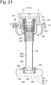
- Fig. 21 is a schematic cross-sectional view schematically showing a state in which a first attaching step is being executed.
- Fig. 22 is a schematic cross-sectional view schematically showing a state after a replaceable component 5 is attached to a beverage extraction pipe 45.
- Fig. 23 is a schematic cross-sectional view schematically showing a state in which an inserting step is being executed.
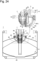
- Fig. 24 is a schematic cross-sectional view schematically showing a state in which a beverage filling step is being executed.
- Fig. 21 is a schematic cross-sectional view schematically showing a state in which a first attaching step is being executed.
- Fig. 22 is a schematic cross-sectional view schematically showing a state after a replaceable component 5 is attached to a beverage extraction pipe 45.
- Fig. 23 is a schematic cross-sectional view schematically showing a state in which an inserting step is being executed.
- Fig. 24 is a schematic cross-sectional view schematically showing
- FIG. 25 is a schematic cross-sectional view schematically showing a state in which a beverage extraction step is being executed.
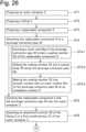
- Fig. 26 is a flowchart showing an example of a method of assembling a beverage container.
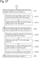
- Fig. 27 is a flowchart showing an example of a method of handling a beverage container.
- a method of assembling a beverage container according to some embodiments constitutes a part of a method of handling a beverage container according to some embodiments.
- a beverage container 1 assembled using the method of assembling a beverage container according to some embodiments may be the beverage container 1A according to the first embodiment, may be the beverage container 1B according to the second embodiment, or may be another beverage container. Since each component of the beverage container 1 has already been described in the first embodiment or the second embodiment, repeated description of each component of the beverage container 1 will be omitted.
- a first step ST1 an outer container 2 having a container main body 22 and a first mouth portion 27 is prepared.
- the first step ST1 is a first preparing step.
- the outer container 2 prepared in the first preparing step is preferably a rigid container (for example, a container made of stainless steel).
- the outer container 2 may be a new container or a reused container prepared by disassembling a beverage container collected from a user.
- a fitting 3 is prepared.
- the second step ST2 is a second preparing step.
- the fitting 3 prepared in the second preparing step may be a new fitting or a reused fitting prepared by disassembling a beverage container collected from a user.
- the fitting 3 prepared in the second preparing step includes (1) an attachment portion 32 attachable to the first mouth portion 27 of the outer container 2, (2) a second mouth portion 34 connectable to a beverage filling nozzle or a dispense head, (3) an annular portion 36 extending outward from the second mouth portion 34 and connecting the second mouth portion 34 and the attachment portion 32, and (4) a beverage extraction pipe 45.
- the fitting 3 prepared in the second preparing step may have a first valve seat portion 341 and a first valve member 37. Also, the fitting 3 prepared in the second preparing step may have a structure M3 including a first spring 38 that biases the first valve member 37 upward, a first spring receiver 39 that supports the first spring 38, and an outer cylindrical portion 40 arranged outside the beverage extraction pipe 45 and protecting the first spring 38. Further, the fitting 3 prepared in the second preparing step may include a second valve member 41 arranged inside the beverage extraction pipe 45, a second spring 42 that biases the second valve member 41 upward, and a second spring receiver 454 that supports the second spring 42. Also, the fitting 3 prepared in the second preparing step may have a removal-preventing member 46 (see Fig. 15 ).
- a replaceable component 5 is prepared.
- the third step ST3 is a third preparing step.
- the replaceable component 5 prepared in the third preparing step is a new replaceable component.
- the replaceable component 5 has (1) a sealing member 52, (2) a tubular body 55 holding the sealing member 52, and (3) a bag 58 for containing a beverage attached to the tubular body 55.
- the first step ST1 (the first preparing step), the second step ST2 (the second preparing step), and the third step ST3 (the third preparing step) may be executed in any order.
- a fourth step ST4 the replaceable component 5 is attached to the beverage extraction pipe 45.
- the fourth step ST4 is a first attaching step. As shown in Fig. 3 etc., in the first attaching step, the sealing member 52 is attached to an upper portion 452 of the beverage extraction pipe 45 by sliding the sealing member 52 relative to the beverage extraction pipe 45.
- the first attaching step also includes attaching the sealing member 52 to the upper portion 452 of the beverage extraction pipe 45 using a frictional force acting between the sealing member 52 and an outer surface 45u of the beverage extraction pipe 45. Since the replaceable component 5 and the beverage extraction pipe 45 are not glued or welded to each other, it is easy to remove the replaceable component 5 from the beverage extraction pipe 45 after the beverage container is collected.
- the first attaching step includes inserting the whole of a lower portion 455 of the beverage extraction pipe 45 and a part of the upper portion 452 of the beverage extraction pipe into the bag 58.
- a sub-step ST4-2 the sealing member 52 and the tubular body 55 are slid along a longitudinal direction of the beverage extraction pipe 45.
- “slide” means relative sliding of the sealing member 52 with respect to the beverage extraction pipe 45. Therefore, “slide” includes both linear movement of the sealing member 52 relative to the beverage extraction pipe 45 and linear movement of the beverage extraction pipe 45 relative to the sealing member 52.
- the lower portion 455 of the beverage extraction pipe 45 includes a small-diameter pipe portion 45a
- the upper portion 452 of the beverage extraction pipe 45 includes a large-diameter pipe portion 45c.
- the sealing member 52 is brought into annular contact with the outer surface 45u of the beverage extraction pipe 45 at an installation position P.
- the sealing member 52 is arranged at the installation position P defined by the upper portion 452 of the beverage extraction pipe 45.
- the sealing member 52 can be slid with respect to the outer surface 45u of the beverage extraction pipe 45 while maintaining a state in which the sealing member 52 is held by the outer surface 45u of the beverage extraction pipe 45.
- degree of freedom of the installation position P of the sealing member 52 with respect to the beverage extraction pipe 45 is large.
- the sealing member 52 can be attached to the beverage extraction pipe 45 at any position between a position P1 and a position P2. When a large degree of freedom is given to the installation position, the sealing member 52 can be quickly and easily attached to the beverage extraction pipe 45.
- the sealing member 52 is attached to the upper portion 452 of the beverage extraction pipe 45 at a position below the lower end of the structure M3.
- the sealing member 52 may be attached to the upper portion 452 of the beverage extraction pipe 45 at a position below a spacer member 63. More specifically, the beverage extraction pipe 45 of the fitting 3 may be inserted into a through hole portion 63h of the spacer member 63, and the sealing member 52 may then be attached to the upper portion 452 of the beverage extraction pipe 45 at the position below the spacer member 63.
- the fitting 3 with the spacer member 63 may be prepared, and in the first attaching step (the fourth step ST4), the sealing member 52 may be attached to the upper portion 452 of the beverage extraction pipe 45 at the position below the spacer member 63.
- the fifth step ST5 is an inserting step. More specifically, the inserting step includes inserting the whole of the beverage extraction pipe 45, the sealing member 52, the tubular body 55 supported by the beverage extraction pipe 45 via the sealing member 52, and the bag 58 attached to the tubular body 55, into the outer container 2 through the first mouth portion 27.
- the beverage extraction pipe 45 is an elongated member and its outer diameter is relatively small. Therefore, it is possible to reduce an outer diameter of the replaceable component 5 attached to the beverage extraction pipe 45. More specifically, the outer diameter of the replaceable component 5 can be reduced by folding the bag 58 constituting a part of the replaceable component 5 around the beverage extraction pipe 45. Further, in an example shown in Fig. 23 , the sealing member 52 is attached to the beverage extraction pipe 45 at the position below the structure M3 or the spacer member 63. In this case, the bag 58 can be arranged compactly around the beverage extraction pipe 45 by utilizing the vertically downward region of the structure M3 or the vertically downward region of the spacer member 63.
- the size of the first mouth portion 27 is set to be larger than the size of the second mouth portion 34 due to the presence of the annular portion 36. Therefore, because the bag 58 of the replaceable component 5 is arranged compactly around the beverage extraction pipe 45 and the size of the first mouth portion 27 is large, the whole of the replaceable component 5 can be smoothly inserted into the outer container 2 through the first mouth portion 27.
- a sixth step ST6 the attachment portion 32 of the fitting 3 is attached to the first mouth portion 27 of the outer container 2.
- the sixth step ST6 is a second attaching step. More specifically, in the second attaching step, the attachment portion 32 of the fitting 3 is threadably engaged with the first mouth portion 27 of the outer container 2.
- the process of filling the beverage container 1 with a beverage constitutes a part of the method of handling the beverage container 1.
- the method of handling the beverage container 1 includes the process of filling the beverage container 1 with a beverage.
- the beverage container 1 is filled with a beverage in a seventh step ST7.
- the seventh step ST7 is a beverage filling step.
- the beverage is filled into the bag 58 which has been arranged inside the outer container 2.
- Fig. 24 shows the beverage filling step in progress.
- the beverage filling nozzle 7 When filling the bag 58 with the beverage, firstly, the beverage filling nozzle 7 is inserted into the second mouth portion 34 of the fitting 3 in a sub-step ST7-1. In an example shown in Fig. 24 , by inserting the beverage filling nozzle 7 into the second mouth portion 34 of the fitting 3, the gas valve V1 and the beverage valve V2 are opened.
- a sub-step ST7-2 the beverage is supplied from the beverage filling nozzle 7 into the bag 58 as indicated by an arrow E1 in Fig. 24 , and gas (more specifically, air) existing in a space SP3 between the outer container 2 and the bag 58 is discharged to the outside of the outer container 2 as indicated by an arrow E2 in Fig. 24 .
- gas more specifically, air
- the bag 58 is filled with the beverage.
- the beverage is supplied into the bag 58 via the beverage valve V2, and the gas is discharged out of the beverage container 1 via the gas valve V1.
- the spacer member 63 is arranged between the annular portion 36 and the tubular body 55.
- the spacer member 63 prevents over deformation (excessive deformation) of the bag 58 toward the annular portion 36 when the bag 58 is inflated by being filled with the beverage. In this way, damage to the bag 58 is prevented.
- the spacer member 63 prevents the bag 58 from coming into contact with the outer cylindrical portion 40 (for example, the through hole portion 40h of the outer cylindrical portion 40) when the bag 58 is inflated. In the example shown in Fig. 24 , the spacer member 63 prevents the bag 58 from coming into contact with the removal-preventing member 46 when the bag 58 is inflated. In this way, damage to the bag 58 is prevented.
- the process of taking out the beverage from the beverage container 1 constitutes a part of the method of handling the beverage container 1.
- the method of handling the beverage container 1 includes the process of taking out the beverage from the beverage container 1.
- the eighth step ST8 is a beverage extraction step.
- the beverage is taken out of the bag 58 which has been arranged inside the outer container 2.
- Fig. 25 shows the beverage extraction step in progress. The extraction of the beverage from the bag 58 is performed via the dispense head 8, for example.
- the dispense head 8 is attached to the second mouth portion 34 of the fitting 3.
- the mounting is performed by, for example, engaging an engaging portion 81 formed in the main body 80 of the dispense head 8 with an engaging portion 345 of the fitting 3.
- a plunger member 85 of the dispense head 8 is moved downward with respect to the main body 80 of the dispense head 8.
- the gas valve V1 and the beverage valve V2 are opened.
- the gas valve V1 and the beverage valve V2 are opened.
- gas for example, air
- the sub-step ST8-3 is a gas supplying step.
- the gas supplied from a gas supply source (for example, an air pump) is introduced into a gas inlet hole 80h (see an arrow E3 in Fig. 25 ).
- the gas introduced into the gas inlet hole 80h is supplied to the space SP3 between the outer container 2 and the bag 58 via a gas flow channel F2 and the gas valve V1 (see an arrow E4 in Fig. 25 ).
- the gas supplied to the space SP3 presses the bag 58 so that the bag 58 contracts.
- the beverage is taken out of the bag 58.
- the beverage is taken out via the beverage valve V2 and the dispense head 8.
- the sub-step ST8-4 will be described in more detail.
- the bag 58 is being bushed downward or inward. Therefore, the beverage in the bag 58 goes to the beverage valve V2 through the inner space of the beverage extraction pipe 45. Since the beverage valve V2 is opened in the above-mentioned sub-step ST8-2 (more specifically, the beverage valve opening step), the beverage in the inner space of the beverage extraction pipe 45 is taken out to the outside of the dispense head 8 via the beverage valve V2 and a beverage flow channel F3 of the plunger member 85 (see an arrow E5 in Fig. 25 ).
- the beverage is taken out of the bag 58 by supplying the gas to the space SP3 between the outer container 2 and the bag 58. Therefore, the beverage in bag 58 does not come in contact with the supply gas (for example, air) supplied via the dispense head 8. Therefore, the taste, texture, and the like of the beverage do not deteriorate due to the contact of the beverage with the supplied gas. Moreover, when the beverage is a sparkling beverage such as beer, the feel of the foam does not deteriorate.
- the supply gas for example, air
- the method of taking out the beverage it is possible to use air as the gas to be supplied to the space SP3 between the outer container 2 and the bag 58. Therefore, it is not necessary to prepare a carbon dioxide gas cylinder, unlike the conventional method of taking out the beverage.
- air as the gas to be supplied to the space SP3 is an optional configuration. In other words, in some embodiments, as the gas to be supplied to the space SP3 between the outer container 2 and the bag 58, the use of gas other than air (for example, carbon dioxide gas) is not excluded.
- the outer container 2 When the outer container 2 is made of stainless steel, durability and corrosion resistance of the outer container 2 are extremely high, and light-shielding property is excellent. Therefore, the outer container 2 with the bag 58 arranged therein may be stored outdoors.
- the process of disassembling the beverage container 1 constitutes a part of the method of handling the beverage container 1.
- the method of handling the beverage container 1 includes the process of disassembling the beverage container 1.
- the ninth step ST9 is a disassembling step. Needless to say, the dispense head 8 is removed from the fitting 3 before the disassembling step is performed.
- the disassembling step includes taking out the beverage extraction pipe 45 and the replaceable component 5 from the outer container 2 and removing the replaceable component 5 from the fitting 3.
- Removing the replaceable component 5 from the fitting 3 includes sliding the sealing member 52 and the tubular body 55 of the replaceable component 5 along the beverage extraction pipe 45 in a direction toward the lower end 45g of the beverage extraction pipe 45.
- the replaceable component 5 can be removed from the beverage extraction pipe 45 simply by sliding the sealing member 52 and the tubular body 55 along the beverage extraction pipe 45. Therefore, it is possible to quickly and easily remove the replaceable component 5 from the beverage extraction pipe 45.
- the fitting 3 from which the replaceable component 5 has been removed and the outer container 2 are preferably reused in the next beverage filling.
- replaceable component 5 is preferably replaced with another replaceable component (more specifically, a new replaceable component). Note that, since the structure of the replaceable component 5 according to some embodiments is simple, manufacturing cost of the replaceable component 5 is low.
- the bag 58 is filled with the beverage and the beverage does not come in direct contact with the reusable outer container 2. Therefore, safety of the beverage is reliably ensured. In addition, since the beverage does not come in direct contact with the reusable outer container 2, adhesion of organic substances (dirt) or odors to the interior of the outer container 2 is suppressed. From the foregoing, it becomes easy to manage the outer container when the outer container 2 is collected and reused. Moreover, it is possible to simplify a process of cleaning the outer container 2.
- each embodiment or each modified example can be appropriately modified or can be changed within the scope of the technical idea of the present invention.
- the various techniques used in each embodiment or each modified example can be applied to other embodiments or other modified examples as long as there is no technical contradiction.
- any optional configuration in each embodiment or each modified example can be omitted as appropriate.
Landscapes
- Engineering & Computer Science (AREA)
- Mechanical Engineering (AREA)
- Packages (AREA)
- Packging For Living Organisms, Food Or Medicinal Products That Are Sensitive To Environmental Conditiond (AREA)
- Devices For Dispensing Beverages (AREA)
Abstract
Description
- The present invention relates to a beverage container and a method of assembling a beverage container.
- A beverage container having a rigid outer container and a flexible inner container is known.
- As a related art,
Patent Literature 1 discloses a container containing a storage bag. The container described inPatent Literature 1 includes an outer container (5) having an opening (22), a storage bag (1) accommodated in the outer container (5) and having a spout (4), and a lid portion (8) connected to both the storage bag and the outer container. InPatent Literature 1, it is described that the hole portion of the spout (4) and the hole portion of the lid portion (8) are fitted, and that the spout (4) and the pouring nozzle (6) are connected. -
Patent Literature 2 discloses a flexible container produced from a film material. The flexible container described inPatent Literature 2 includes a cap (5) attached to a neck of a rigid outer container (2), a fixing lip (4) forming a part of the cap (5), a bag (3) that is fixed to the fixing lip (4), a shut-off valve (10) that can be pushed downward, and a dispenser tube (8). -
Patent Literature 3 discloses a beverage supply device. The beverage supply device described inPatent Literature 3 includes a container body (20) including a neck part (22), a flexible bag body (90) arranged inside the container body (20), a cap (30), and a cylinder body (50) . -
- [Patent Literature 1]
WO 2015/156085 A1 - [Patent Literature 2]
WO 2001/000502 A1 - [Patent Literature 3]
JP 2018-30639 A - An object of the present invention is to provide a technique for facilitating the assembly of a beverage container including an outer container, a fitting, and a replaceable component having a bag.
- A beverage container according to some embodiments includes an outer container having a first mouth portion, a fitting having a beverage extraction pipe, and a replaceable component attached to the beverage extraction pipe and arranged in an inner space of the outer container. The fitting includes an attachment portion attached to the first mouth portion of the outer container, a second mouth portion connectable to a beverage filling nozzle or a dispense head, an annular portion extending outward from the second mouth portion and connecting the second mouth portion and the attachment portion, and the beverage extraction pipe extending toward a bottom of the outer container. The replaceable component includes a sealing member slidable along a longitudinal direction of the beverage extraction pipe and being in annular contact with an outer surface of the beverage extraction pipe at an installation position, a tubular body holding the sealing member and being supported by the beverage extraction pipe via the sealing member located at the installation position, and a bag for containing a beverage attached to the tubular body.
- A method of assembling a beverage container according to some embodiments includes: preparing an outer container having a first mouth portion; preparing a fitting having an attachment portion attachable to the first mouth portion, a second mouth portion connectable to a beverage filling nozzle or a dispense head, an annular portion extending outward from the second mouth portion connecting the second mouth portion and the attachment portion, and a beverage extraction pipe; preparing a replaceable component having a sealing member, a tubular body holding the sealing member, and a bag for containing a beverage attached to the tubular body; attaching the replaceable component to the beverage extraction pipe; inserting the replaceable component and the beverage extraction pipe into the outer container; and attaching the attachment portion of the fitting to the first mouth portion of the outer container. The attaching the replaceable component to the beverage extraction pipe includes: sliding the sealing member and the tubular body along a longitudinal direction of the beverage extraction pipe; and making the sealing member into annular contact with an outer surface of the beverage extraction pipe at an installation position. The inserting the replaceable component and the beverage extraction pipe into the outer container includes: inserting a whole of the beverage extraction pipe, the sealing member, the tubular body supported by the beverage extraction pipe via the sealing member, and the bag attached to the tubular body into the outer container through the first mouth portion.
- According to the present invention, it is possible to provide a technique for facilitating the assembly of a beverage container including an outer container, a fitting, and a replaceable component having a bag.
-
-
Fig. 1 is a schematic cross-sectional view schematically showing a beverage container according to a first embodiment. -
Fig. 2 is a schematic cross-sectional view schematically showing the beverage container according to the first embodiment. -
Fig. 3 is a schematic cross-sectional view schematically showing how a replaceable component is attached to a beverage extraction pipe. -
Fig. 4 is a schematic cross-sectional view schematically showing a state after the replaceable component is attached to the beverage extraction pipe. -
Fig. 5 is a schematic two-view schematically showing an example of a fitting. -
Fig. 6 is a schematic cross-sectional view schematically showing the beverage container according to a first modified example of the first embodiment. -
Fig. 7 is a schematic cross-sectional view schematically showing the beverage container according to the first embodiment. -
Fig. 8 is a schematic cross-sectional view schematically showing a part of the beverage container according to the first embodiment. -
Fig. 9 is a schematic two-view schematically showing an example of a spacer member. -
Fig. 10 is a schematic cross-sectional view schematically showing a state after the replaceable component is attached to the beverage extraction pipe. -
Fig. 11 is a schematic cross-sectional view schematically showing a part of the beverage container according to the first embodiment. -
Fig. 12 is a schematic cross-sectional view schematically showing a part of the beverage container according to a second modified example of the first embodiment. -
Fig. 13 is a diagram for explaining each element of the replaceable component. -
Fig. 14 is a schematic two-view schematically showing an example of the replaceable component. -
Fig. 15 is a schematic cross-sectional view schematically showing the beverage container according to the first embodiment. -
Fig. 16 is a schematic cross-sectional view schematically showing the beverage container according to the first embodiment. -
Fig. 17 is a schematic cross-sectional view schematically showing a first modified example of a removal-preventing member. -
Fig. 18 is a schematic cross-sectional view schematically showing a second modified example of the removal-preventing member. -
Fig. 19 is a schematic cross-sectional view schematically showing a beverage container according to a second embodiment. -
Fig. 20 is a schematic cross-sectional view schematically showing a part of the beverage container according to the second embodiment. -
Fig. 21 is a schematic cross-sectional view schematically showing a state in which a first attaching step is being executed. -
Fig. 22 is a schematic cross-sectional view schematically showing a state after a replaceable component is attached to a beverage extraction pipe. -
Fig. 23 is a schematic cross-sectional view schematically showing a state in which an inserting step is being executed. -
Fig. 24 is a schematic cross-sectional view schematically showing a state in which a beverage filling step is being executed. -
Fig. 25 is a schematic cross-sectional view schematically showing a state in which a beverage extraction step is being executed. -
Fig. 26 is a flowchart showing an example of a method of assembling a beverage container. -
Fig. 27 is a flowchart showing an example of a method of handling a beverage container. - Hereinafter, a
beverage container 1 and a method of assembling thebeverage container 1 according to some embodiments will be described with reference to the drawings. In the following description, members and portions having the same functions are denoted by the same reference numerals, and repeated descriptions of members and portions denoted by the same reference numerals are omitted. - In this specification, a direction from a
bottom portion 23 of anouter container 2 toward afirst mouth portion 27 of theouter container 2 is defined as "upward" and a direction from thefirst mouth portion 27 to thebottom portion 23 is defined as "downward". Therefore, regardless of whether theouter container 2 is in the upright posture or the inverted posture, the direction from thebottom portion 23 to thefirst mouth portion 27 is "upward". Further, regarding afitting 3 before being attached to theouter container 2, a direction from alower end 45g of abeverage extraction pipe 45 toward anupper end 45e of thebeverage extraction pipe 45 is defined as "upward", and a direction from theupper end 45e toward thelower end 45g is defined as "downward". - In this specification, a term "outward" means a direction away from a central axis C1 of a
second mouth portion 34 of the fitting 3 (or a direction away from a central axis C2 of the beverage extraction pipe 45). Further, a term "inward" means a direction toward the central axis C1 of thesecond mouth portion 34 of the fitting 3 (or a direction toward the central axis C2 of the beverage extraction pipe 45). - Referring to
Figs. 1 to 18 , abeverage container 1A according to a first embodiment will be described.Figs. 1 and2 are schematic cross-sectional views schematically showing abeverage container 1A according to a first embodiment. Note thatFig. 1 shows a state before thebeverage container 1A is assembled, andFig. 2 shows a state after thebeverage container 1A is assembled.Fig. 3 is a schematic cross-sectional view schematically showing how areplaceable component 5 is attached to abeverage extraction pipe 45.Fig. 4 is a schematic cross-sectional view schematically showing a state after thereplaceable component 5 is attached to thebeverage extraction pipe 45.Fig. 5 is a schematic two-view schematically showing an example of afitting 3. A schematic plan view is shown on the upper side ofFig. 5 , and a schematic cross-sectional view is shown on the lower side ofFig 5 .Fig. 6 is a schematic cross-sectional view schematically showing thebeverage container 1A according to a first modified example of the first embodiment.Fig. 7 is a schematic cross-sectional view schematically showing thebeverage container 1A (an example in which thebeverage container 1A includes a spacer member 63) according to the first embodiment.Fig. 8 is a schematic cross-sectional view schematically showing a part of thebeverage container 1A according to the first embodiment.Fig. 9 is a schematic two-view schematically showing an example of thespacer member 63. A schematic plan view is shown on the upper side ofFig. 9 , and a schematic cross-sectional view is shown on the lower side ofFig. 9 .Fig. 10 is a schematic cross-sectional view schematically showing a state after thereplaceable component 5 is attached to thebeverage extraction pipe 45.Fig. 11 is a schematic cross-sectional view schematically showing a part of thebeverage container 1A according to the first embodiment.Fig. 12 is a schematic cross-sectional view schematically showing a part of thebeverage container 1A according to a second modified example of the first embodiment.Fig. 13 is a diagram for explaining each element of thereplaceable component 5.Fig. 14 is a schematic two-view schematically showing an example of thereplaceable component 5. A schematic plan view is shown on the upper side ofFig. 14 , and a schematic cross-sectional view is shown on the lower side ofFig 14 .Figs. 15 and16 are schematic cross-sectional views schematically showing thebeverage container 1A (an example in which thebeverage container 1A includes a removal-preventing member 46) according to the first embodiment.Fig. 17 is a schematic cross-sectional view schematically showing a first modified example of the removal-preventingmember 46.Fig. 18 is a schematic cross-sectional view schematically showing a second modified example of the removal-preventingmember 46. - As shown in
Fig. 1 , abeverage container 1A includes anouter container 2, afitting 3, and areplaceable component 5 including abag 58. - The
outer container 2 defines an inner space SP1 in which thereplaceable component 5 including thebag 58 is arranged. Theouter container 2 has a containermain body 22 and afirst mouth portion 27. In an example shown inFig. 1 , thefirst mouth portion 27 extends upward from the containermain body 22. Theouter container 2 is made of, for example, metal (more specifically, stainless steel). Alternatively, theouter container 2 may be made of resin. - The
fitting 3 is attached to thefirst mouth portion 27. In the example shown inFig. 1 , thefirst mouth portion 27 has a first threadedportion 27s (more specifically, a male threaded portion). Thefirst mouth portion 27 defines a first opening OP1 through which thereplaceable component 5 can pass. - The
fitting 3 includes anattachment portion 32, asecond mouth portion 34, anannular portion 36, and abeverage extraction pipe 45. Note that, in this specification, a "fitting" means a member attached to the first mouth portion of the outer container and used for filling the bag with a beverage and / or taking out a beverage from the bag. - The
attachment portion 32 is attached to thefirst mouth portion 27 of theouter container 2. In the example shown inFig. 1 , theattachment portion 32 has a second threadedportion 32s (more specifically, a female threaded portion) threadably engaging with the first threadedportion 27s of thefirst mouth portion 27. Theattachment portion 32 is made of, for example, metal (more specifically, stainless steel). Alternatively, theattachment portion 32 may be made of resin. - The
second mouth portion 34 can be connected to a beverage filling nozzle or a dispense head. Thesecond mouth portion 34 defines a second opening OP2 through which a tip portion of the beverage filling nozzle (or a tip portion of a plunger member of the dispense head) can pass. - In the example shown in
Fig. 1 , thesecond mouth portion 34 has an engagingportion 345 engageable with the dispense head. Thesecond mouth portion 34 is made of, for example, metal (more specifically, stainless steel). Alternatively, thesecond mouth portion 34 may be made of resin. - The
annular portion 36 extends outward from thesecond mouth portion 34. (In other words, theannular portion 36 extends from thesecond mouth portion 34 in a direction away from a central axis C1 of the second mouth portion 34). Further, theannular portion 36 connects thesecond mouth portion 34 and theattachment portion 32. In the example shown inFig. 1 , theannular portion 36 has aninner portion 36n connected to thesecond mouth portion 34 and anouter portion 36u connected to theattachment portion 32. In the example shown inFig. 1 , an inner peripheral edge portion of theannular portion 36 is connected to thesecond mouth portion 34, and an outer peripheral edge portion of theannular portion 36 is connected to theattachment portion 32. An upper surface of theannular portion 36 may be a plane parallel to a horizontal plane or a plane inclined with respect to the horizontal plane. - Since the
fitting 3 has theannular portion 36, an inner diameter of thefirst mouth portion 27 of theouter container 2 can be remarkably larger than an inner diameter of thesecond mouth portion 34 of thefitting 3. When the inner diameter of thefirst mouth portion 27 is large, it is easy to insert thereplaceable component 5 having thebag 58 into theouter container 2 via thefirst mouth portion 27. - As shown in
Fig. 2 , thebeverage extraction pipe 45 extends toward abottom portion 23 of theouter container 2. Further, anupper end 45e of thebeverage extraction pipe 45 is arranged in a vicinity of thesecond mouth portion 34. Thebeverage extraction pipe 45 has aninner surface 45n that defines a beverage flow channel Fl. When the beverage is taken out of thebeverage container 1A, the beverage D in thebag 58 is introduced into thebeverage extraction pipe 45, and the beverage D introduced into thebeverage extraction pipe 45 flows toward theupper end 45e of thebeverage extraction pipe 45. Thebeverage extraction pipe 45 is made of, for example, metal (more specifically, stainless steel). Alternatively, thebeverage extraction pipe 45 may be made of resin. - The
replaceable component 5 is attached to thebeverage extraction pipe 45 and is arranged in the inner space SP1 of theouter container 2. In an example shown inFig. 2 , a whole of thereplaceable component 5 and a whole of thebeverage extraction pipe 45 are arranged in the inner space SP1 of theouter container 2. - As shown in
Fig. 3 , thereplaceable component 5 includes a sealingmember 52, atubular body 55, and thebag 58. The frequency of replacing thereplaceable component 5 is higher than the frequency of replacing theouter container 2 and thefitting 3. By repeatedly reusing theouter container 2 and thefitting 3, the burden on the environment is reduced. When one cycle is defined as from the filling of the beverage into thebeverage container 1A to the next filling of the beverage into thebeverage container 1A, thereplaceable component 5 may be replaced every cycle. In other words, thereplaceable component 5 may be a one-time use disposable component. - The sealing
member 52 is slidable along a longitudinal direction of thebeverage extraction pipe 45. In this case, it is easy to move the sealingmember 52 toward an installation position P (more specifically, anupper portion 452 of the beverage extraction pipe 45) on thebeverage extraction pipe 45, and it is easy to arrange the sealingmember 52 at the installation position P (more specifically, theupper portion 452 of the beverage extraction pipe 45) on thebeverage extraction pipe 45. - At a final stage when the sealing
member 52 reaches the installation position P, the sealingmember 52 slides with respect to thebeverage extraction pipe 45 in a state where anouter surface 45u of thebeverage extraction pipe 45 and the sealingmember 52 are in annular contact with each other. In other words, at the final stage when the sealingmember 52 reaches the installation position P, an appropriate frictional resistance is generated between the sealingmember 52 and thebeverage extraction pipe 45. Note that if the frictional resistance is too small, the sealingmember 52 may be determined to be a defective product. - As shown in
Fig. 4 , the sealingmember 52 is in annular contact with theouter surface 45u of thebeverage extraction pipe 45 when it is located at the installation position P. This contact prevents fluid (in other words, the beverage or a gas) from leaking from between the sealingmember 52 and thebeverage extraction pipe 45. The sealingmember 52 is made of an elastic material such as rubber. - The
tubular body 55 is arranged outside the sealingmember 52 and holds the sealingmember 52. When the sealingmember 52 is located at the installation position P on thebeverage extraction pipe 45, thetubular body 55 prevents an outer diameter of the sealingmember 52 from increasing. In this way, the sealingmember 52 arranged between thetubular body 55 and theouter surface 45u of thebeverage extraction pipe 45 is compressed, and the sealing effect of the sealingmember 52 is improved. - As shown in
Fig. 4 , thetubular body 55 is supported by thebeverage extraction pipe 45 via the sealingmember 52 located at the installation position P. Further, thebag 58 for accommodating the beverage is attached to thetubular body 55. The beverage contained in thebag 58 is, for example, an alcoholic beverage such as beer, or an effervescent beverage such as beer or non-alcoholic beer. - In an example shown in
Fig. 4 , when the sealingmember 52 is located at the installation position P, thetubular body 55 to which thebag 58 is attached is supported by thebeverage extraction pipe 45 via the sealingmember 52. In other words, only by moving the sealingmember 52 to the installation position P, thereplaceable component 5 including thebag 58 is supported by thebeverage extraction pipe 45. Therefore, the configuration for preventing thereplaceable component 5 from falling off from thebeverage extraction pipe 45 is simple. - In the first embodiment, by sliding the sealing
member 52 toward the installation position P on thebeverage extraction pipe 45, thereplaceable component 5 having the sealingmember 52 is attached to thebeverage extraction pipe 45. Therefore, it is easy to attach thereplaceable component 5 to the beverage extraction pipe 45 (seeFigs. 3 and4 ). - Further, in the first embodiment, the
replaceable component 5 having thebag 58 is attached to thebeverage extraction pipe 45. In this case, thebag 58 can be compactly arranged around thebeverage extraction pipe 45. Therefore, thereplaceable component 5 having thebag 58 and thebeverage extraction pipe 45 to which thereplaceable component 5 is attached can be easily inserted into the outer container 2 (seeFig. 1 ). - Further, in the first embodiment, the
fitting 3 has theannular portion 36. Due to the presence of theannular portion 36, the inner diameter of thefirst mouth portion 27 of theouter container 2 can be remarkably larger than the inner diameter of thesecond mouth portion 34 of thefitting 3. When the inner diameter of thefirst mouth portion 27 is large, it is easy to insert thereplaceable component 5 having thebag 58 into theouter container 2 through the first mouth portion 27 (seeFig. 1 ). - As mentioned above, in the first embodiment, the
beverage container 1A that is easy to assemble is provided. - Subsequently, with reference to
Figs. 1 to 18 , optional configurations that can be adopted in the first embodiment will be described. - In the example shown in
Fig. 1 , theouter container 2 is a rigid container (in other words, a container whose shape does not substantially change). The containermain body 22 of theouter container 2 has thebottom portion 23 and abody portion 24. The containermain body 22 may have anupper plate portion 25 that connects thebody portion 24 and thefirst mouth portion 27. In the example shown inFig. 1 , theupper plate portion 25 and thefirst mouth portion 27 are connected via a weldedportion 26. - In an example shown in
Fig. 5 , thefitting 3 is an assemble body M1 including theattachment portion 32, thesecond mouth portion 34, theannular portion 36, and thebeverage extraction pipe 45. The assemble body M1 may include afirst valve member 37 described later, afirst spring 38 described later, and afirst spring receiver 39 described later. Further, the assemble body M1 may include asecond valve member 41 described later, asecond spring 42 described later, and asecond spring receiver 454 described later. - It is preferable that the fitting 3 assembled in the assemble body M1 is attached to the
first mouth portion 27 of theouter container 2 so that the whole of thefitting 3 is attached to theouter container 2. In this case, it is not necessary to separately place each member constituting the fitting 3 to theouter container 2. - Alternatively, as shown in
Fig. 6 , thefitting 3 may be divided into a plurality of parts. In an example shown inFig. 6 , theattachment portion 32 and a assemble body M2 of the fitting 3 excluding theouter portion 36u of theannular portion 36 are placed to theouter container 2, and then theattachment portion 32 constituting a part of thefitting 3 is attached to theouter container 2. In the example shown inFig. 6 , theinner portion 36n of theannular portion 36 and theouter portion 36u of theannular portion 36 are separate bodies. Further, when theattachment portion 32 is attached to thefirst mouth portion 27 of theouter container 2, theinner portion 36n of theannular portion 36 and theouter portion 36u of theannular portion 36 are connected by pressing force. - In an example shown in
Fig. 7 , thebeverage container 1A includes aspacer member 63 arranged between theannular portion 36 and thetubular body 55. Thespacer member 63 prevents over-deformation (excessive-deformation) of thebag 58 toward theannular portion 36. In the example shown inFig. 7 , thespacer member 63 is not attached to thetubular body 55. In other words, thetubular body 55 is movable relative to thespacer member 63. In this case, thespacer member 63 and thereplaceable component 5 having thetubular body 55 can be handled separately. For example, the frequency of replacing thespacer member 63 can be made lower than the frequency of replacing thereplaceable component 5. - The
spacer member 63 is preferably a non-flexible member (in other words, a member whose substantial deformation is suppressed). Thespacer member 63 may be made of resin, or may be made of metal such as stainless steel. - In the example shown in
Fig. 2 , when an internal pressure of thebag 58 increases, a part of thebag 58 enters an annular region AR1 inside thefirst mouth portion 27, and thebag 58 is over-deformed upward. In addition, thebag 58 may be damaged due to over-deformation of thebag 58. On the other hand, thespacer member 63 prevents thebag 58 from being over-deformed toward theannular portion 36 since the spacer member occupies a part of the annular region AR1 inside thefirst mouth portion 27. - In the example shown in
Fig. 7 , thespacer member 63 prevents thebag 58 from coming into contact with an outercylindrical portion 40 described later. In this case, damage to thebag 58 due to contact between thebag 58 and the outer cylindrical portion 40 (more specifically, a throughhole portion 40h formed in the outer cylindrical portion 40) is prevented. - In the example shown in
Fig. 7 , thespacer member 63 has anupper end portion 63e located above alower end 27g of thefirst mouth portion 27. Theupper end portion 63e is arranged in the annular region AR1 between thefirst mouth portion 27 and the outercylindrical portion 40. Theupper end portion 63e of thespacer member 63 may be contactable to theannular portion 36 of thefitting 3. - In the example shown in
Fig. 7 , thespacer member 63 is arranged so as to surround the outercylindrical portion 40, and a lower end of thespacer member 63 is located below a lower end of the outercylindrical portion 40. In this case, thespacer member 63 can effectively prevent thebag 58 from coming into contact with the outer cylindrical portion 40 (more specifically, the throughhole portion 40h) . - In an example shown in
Fig. 8 , thespacer member 63 has alower end portion 63g extending inward toward thebeverage extraction pipe 45. In the example shown inFig. 8 , thelower end portion 63g of thespacer member 63 is located below thelower end 27g of thefirst mouth portion 27. It is preferable that thelower end portion 63g of thespacer member 63 is contactable to the tubular body 55 (more specifically, afirst flange 553 of the tubular body 55) of thereplaceable component 5. - In the example shown in
Fig. 8 , thespacer member 63 has alower surface 63d which is arranged to face thebag 58. Thelower surface 63d is preferably an inclined surface (more specifically, an inclined convex surface) whose height increases as a distance from the central axis C2 of thebeverage extraction pipe 45 increases. In this case, when the internal pressure of thebag 58 increases, thebag 58 is gently deformed along thelower surface 63d of thespacer member 63. As a result, over-deformation of thebag 58 is prevented, and damage to thebag 58 is prevented even more effectively. - In the example shown in
Fig. 8 , thespacer member 63 has a throughhole portion 63h into which thebeverage extraction pipe 45 is inserted. The throughhole portion 63h may be able to receive an upper end portion of thetubular body 55 of thereplaceable component 5. - In the example shown in
Fig. 8 , thetubular body 55 can move relative to thespacer member 63 in a vertical direction. When thetubular body 55 moves upward beyond the throughhole portion 63h of thespacer member 63, thebag 58 may be damaged by an inner edge of the throughhole portion 63h or an outer edge of thetubular body 55. Therefore, in the example shown inFig. 8 , an inner diameter D1 of the throughhole portion 63h of thespacer member 63 is set to a smaller value than a maximum outer diameter D2 of the tubular body 55 (more specifically, an outer diameter of the first flange 553). In the example shown inFig. 8 , thefirst flange 553 of thetubular body 55 cannot move upward beyond the throughhole portion 63h of thespacer member 63. - In the example shown in
Fig. 8 , thespacer member 63 is movable relative to thefitting 3. Alternatively, thespacer member 63 may be fixed to thefitting 3. For example, thespacer member 63 may be fixed to theannular portion 36 of thefitting 3 by engagement (for example thread engagement) or welding. - In the example shown in
Fig. 8 , arecess portion 63f that allows the passage of gas is formed in theupper end portion 63e of thespacer member 63. In this case, the gas supplied from the outside of theouter container 2 can enter a space SP3 between the containermain body 22 of theouter container 2 and thebag 58 through therecess portion 63f. In this way, the beverage inside thebag 58 can be pushed out of thebag 58 by using the pressure of the gas entering the space SP3. Alternatively, anouter shell portion 633 of thespacer member 63 may be provided with a through hole portion that allows the passage of gas, apart from the above-mentioned throughhole portion 63h. - As shown in
Fig. 9 , thespacer member 63 may have theouter shell portion 633 and reinforcingribs 635 arranged inside theouter shell portion 633. The reinforcingribs 635 reinforce theouter shell portion 633 and suppress the deformation of theouter shell portion 633. - In an example shown in
Fig. 10 , thefitting 3 has a firstvalve seat portion 341 and thefirst valve member 37. Further, a gas valve V1 is constituted by the firstvalve seat portion 341 and thefirst valve member 37. The gas valve V1 is a valve whose state can be changed between an open state that allows the passage of gas and a closed state that prohibits the passage of gas. - In the example shown in
Fig. 10 , the firstvalve seat portion 341 is formed in thesecond mouth portion 34. More specifically, a part of an inner peripheral surface of thesecond mouth portion 34 functions as the firstvalve seat portion 341. The firstvalve seat portion 341 is constituted by, for example, an inclined surface whose inner diameter increases in a downward direction. - The
first valve member 37 is contactable to the firstvalve seat portion 341 and is separable from the firstvalve seat portion 341. A state in which thefirst valve member 37 is in contact with the firstvalve seat portion 341 corresponds to the closed state of the gas valve V1, and a state in which thefirst valve member 37 is separated from the firstvalve seat portion 341 corresponds to the open state of the gas valve V1. - In the example shown in
Fig. 10 , thefitting 3 is provided with the gas valve V1. Alternatively, the containermain body 22 of theouter container 2 may be provided with the gas valve, and thefitting 3 may be provided with only a beverage valve. In this case, the firstvalve seat portion 341 formed in thesecond mouth portion 34 may function as a valve seat portion of the beverage valve, and thefirst valve member 37 may function as a valve body of the beverage valve. - In the example shown in
Fig. 10 , the sealingmember 52 is attached to thebeverage extraction pipe 45 at a position below thefirst valve member 37. In this case, an interference between thefirst valve member 37 and members arranged in the vicinity of thefirst valve member 37, and thereplaceable component 5 including the sealingmember 52 is prevented or suppressed. In the example shown inFig. 10 , the sealingmember 52 is arranged vertically below thefirst valve member 37. - In the example shown in
Fig. 10 , both thefirst valve member 37 and the sealingmember 52 are attached to thebeverage extraction pipe 45. More specifically, thefirst valve member 37 is attached to an upper end portion of thebeverage extraction pipe 45, and the sealingmember 52 is attached to theouter surface 45u (in other words, the outer peripheral surface) of thebeverage extraction pipe 45. In this case, when thefirst valve member 37 moves downward so as to be separated from the firstvalve seat portion 341, thebeverage extraction pipe 45 and the sealingmember 52 move downward together with thefirst valve member 37. - (
first spring 38,first spring receiver 39, outer cylindrical portion 40) - In the example shown in
Fig. 10 , thefitting 3 includes thefirst spring 38 and thefirst spring receiver 39 in addition to thefirst valve member 37. Thefitting 3 may include the outercylindrical portion 40. - The
first spring 38 is arranged below thefirst valve member 37 and biases thefirst valve member 37 upward. In this case, the gas valve V1 is maintained in the closed state by a biasing force of thefirst spring 38. On the other hand, the gas valve V1 is opened when thefirst valve member 37 is pushed downward against the biasing force of thefirst spring 38. In the example shown inFig. 10 , thefirst spring 38 is arranged outside thebeverage extraction pipe 45 so as to surround thebeverage extraction pipe 45. - The
first spring receiver 39 is arranged below thefirst spring 38 and supports thefirst spring 38. In the example shown inFig. 10 , thefirst spring receiver 39 is arranged outside thebeverage extraction pipe 45 so as to surround thebeverage extraction pipe 45. - The outer
cylindrical portion 40 is arranged outside thebeverage extraction pipe 45. It is preferable that the outercylindrical portion 40 is provided with a plurality of throughhole portions 40h that allow the passage of gas. In the example shown inFig. 10 , thefirst spring 38 is arranged between the outercylindrical portion 40 and thebeverage extraction pipe 45. In this case, thefirst spring 38 is protected by the outercylindrical portion 40. An upper end portion of the outercylindrical portion 40 is fixed (more specifically, welded) to thesecond mouth portion 34 or theannular portion 36. - In the example shown in
Fig. 10 , alower end portion 40g of the outercylindrical portion 40 supports thefirst spring receiver 39. Alternatively, thelower end portion 40g of the outercylindrical portion 40 may function as thefirst spring receiver 39. - In the example shown in
Fig. 10 , thetubular body 55 of thereplaceable component 5 is arranged vertically below a structure M3 including thefirst spring 38, thefirst spring receiver 39, and the outercylindrical portion 40 that protects thefirst spring 38. In this case, thetubular body 55 and thebag 58 before being filled with the beverage can be compactly arranged around thebeverage extraction pipe 45 by utilizing a region vertically below the structure M3. Therefore, thereplaceable component 5 having thetubular body 55 and thebag 58 can be easily inserted into theouter container 2 via thefirst mouth portion 27. In this way, thebeverage container 1A can be easily assembled. In the example shown inFig. 10 , atubular portion 551 of thetubular body 55 and the sealingmember 52 are arranged in a space inside a virtual cylinder (see the virtual cylinder indicated by a dashed line A) which is formed by virtually extending an outer edge of the outercylindrical portion 40 downward. - The
fitting 3 may have a secondvalve seat portion 371 and thesecond valve member 41. A beverage valve V2 is constituted by the secondvalve seat portion 371 and thesecond valve member 41. The beverage valve V2 is a valve whose state can be changed between an open state that allows the passage of the beverage and a closed state that prohibits the passage of the beverage. - In the example shown in
Fig. 10 , the secondvalve seat portion 371 is formed in thefirst valve member 37. More specifically, an inner peripheral surface of a lower end portion of thefirst valve member 37 functions as the secondvalve seat portion 371. The secondvalve seat portion 371 is constituted by, for example, an inclined surface whose inner diameter increases in a downward direction. - The
second valve member 41 is contactable to the secondvalve seat portion 371 and is separable from the secondvalve seat portion 371. A state in which thesecond valve member 41 is in contact with the secondvalve seat portion 371 corresponds to the closed state of the beverage valve V2, and a state in which thesecond valve member 41 is separated from the secondvalve seat portion 371 corresponds to the open state of the beverage valve V2. In the example shown inFig. 10 , thesecond valve member 41 is arranged inside thebeverage extraction pipe 45. Further, thesecond valve member 41 can move in the vertical direction in the internal space of thebeverage extraction pipe 45. - In the example shown in
Fig. 10 , thefitting 3 includes thesecond spring 42 and thesecond spring receiver 454 in addition to thesecond valve member 41. - The
second spring 42 is arranged below thesecond valve member 41 and biases thesecond valve member 41 upward. In this case, the beverage valve V2 is maintained in the closed state by a biasing force of thesecond spring 42. On the other hand, the beverage valve V2 is opened when thesecond valve member 41 is pushed downward against the biasing force of thesecond spring 42. In the example shown inFig. 10 , thesecond spring 42 is arranged inside thebeverage extraction pipe 45. - The
second spring receiver 454 is arranged below thesecond spring 42 and supports thesecond spring 42. In the example shown inFig. 10 , thesecond spring receiver 454 is constituted by a stepped portion (in other words, a portion where an inner diameter changes) of thebeverage extraction pipe 45. - In the example shown in
Fig. 10 , the sealingmember 52 of thereplaceable component 5 is arranged below thesecond valve member 41 and above thesecond spring receiver 454. - As shown in
Fig. 11 , thesecond mouth portion 34 of thefitting 3 is preferably arranged above thefirst mouth portion 27 of theouter container 2. In an example shown inFig. 11 , thesecond mouth portion 34 of thefitting 3 is arranged so as to extend upward from theannular portion 36, and theattachment portion 32 of thefitting 3 is arranged so as to extend downward from theannular portion 36. In this way, thesecond mouth portion 34 is arranged above thefirst mouth portion 27 to which theattachment portion 32 is attached. - When the
second mouth portion 34 is arranged at a high position, thefirst valve member 37 that contacts the firstvalve seat portion 341 of thesecond mouth portion 34 can be arranged at a higher position. In the example shown inFig. 11 , an upper end surface of thefirst valve member 37 is arranged at a position higher than thelower end 27g of thefirst mouth portion 27. In addition, the upper end surface of thefirst valve member 37 is arranged at a position higher than anupper surface 27e of thefirst mouth portion 27. - When the
first valve member 37 is arranged at a high position, the sealingmember 52 and thetubular body 55 arranged below thefirst valve member 37 can be arranged at a higher position. Further, when thetubular body 55 is arranged at a high position, a height difference H1 between thelower end 27g of thefirst mouth portion 27 and a attaching position of thebag 58 to thetubular body 55 is reduced. Due to the reduction in the height difference H1, thebag 58 is prevented from being greatly deformed upward due to the increase of the internal pressure of thebag 58. - In the example shown in
Fig. 11 , an inner diameter D3 of thefirst mouth portion 27 is remarkably larger than an inner diameter D4 of theannular portion 36. When the inner diameter D3 of thefirst mouth portion 27 is large, it is easy to insert thereplaceable component 5 having thebag 58 into theouter container 2 through thefirst mouth portion 27. The inner diameter D3 of thefirst mouth portion 27 is, for example, 6 cm or more and 12 cm or less, or 7 cm or more and 10 cm or less. The inner diameter D3 of thefirst mouth portion 27 is preferably at least 1.5 times larger, or at least 1.8 times larger than the inner diameter D4 of theannular portion 36. Further, from the viewpoint of allowing thetubular body 55 and thebag 58 attached to thetubular body 55 to be easily inserted into theouter container 2, it is preferable that the inner diameter D3 of thefirst mouth portion 27 is sufficiently larger than the maximum outer diameter D2 of the tubular body 55 (more specifically, the outer diameter of the first flange 553). The difference between the inner diameter D3 of thefirst mouth portion 27 and the maximum outer diameter D2 of the tubular body 55 (more specifically, the outer diameter of the first flange 553) is, for example, 15 mm or more, 20 mm or more, or 25 mm or more. In the example shown inFig. 11 , the maximum outer diameter D2 of thetubular body 55 is larger than the inner diameter D4 of theannular portion 36 and smaller than the inner diameter D3 of thefirst mouth portion 27. - In the example shown in
Fig. 11 , the first threadedportion 27s of thefirst mouth portion 27 of theouter container 2 is a male threaded portion. Since the first threadedportion 27s is a male threaded portion (in other words, an external threaded portion), aninner surface 27n of thefirst mouth portion 27 can be made smooth. In a case in which theinner surface 27n of thefirst mouth portion 27 is a smooth surface, thebag 58 is less likely to get caught on theinner surface 27n of thefirst mouth portion 27, when thereplaceable component 5 having thebag 58 is inserted into theouter container 2 through thefirst mouth portion 27. In this way, thebeverage container 1A is easily assembled. - Alternatively, as shown in
Fig. 12 , the first threadedportion 27s of thefirst mouth portion 27 of theouter container 2 may be a female threaded portion, and the second threadedportion 32s of theattachment portion 32 of the fitting 3 may be a male threaded portion. - As shown in
Fig. 11 , a lower end surface of thefirst mouth portion 27 may be aninclined surface 27t whose inner diameter decreases in an upward direction. Theinclined surface 27t may be a tapered surface or an R surface (in other words, a convex arcuate surface). Since the lower end surface of thefirst mouth portion 27 is aninclined surface 27t whose inner diameter decreases in an upward direction, thebag 58 is smoothly reduced in diameter by theinclined surface 27t when thereplaceable component 5 is taken out of theouter container 2. In this way, thebag 58 which is bulky can be smoothly removed from theouter container 2 through thefirst mouth portion 27. - In the example shown in
Fig. 11 , thesecond mouth portion 34 of thefitting 3 has arecess portion 347 capable of receiving a lower end of a dispense head main body 80 (seeFig. 25 if necessary). Thesecond mouth portion 34 may have ashoulder portion 348 that positions the lower end of the dispense headmain body 80. Further, thesecond mouth portion 34 may have an annular outward protrudingportion 349 at the upper end. - In the example shown in
Fig. 11 , thebeverage container 1A includes a sealingring 65 arranged between thefirst mouth portion 27 and theannular portion 36. The sealingring 65 prevents gas from leaking out from a gap between theouter container 2 and thefitting 3. - In the example shown in
Fig. 11 , theupper surface 27e of thefirst mouth portion 27 and alower surface 36g of theannular portion 36 are in surface-to-surface contact with each other in a state in which the sealingring 65 is compressed. Due to the surface-to-surface contact, an amount of compression of the sealingring 65 is maintained at an appropriate value. In other words, damage to the sealingring 65 due to excessive compression is prevented, and a stable sealing effect by the sealingring 65 is maintained. - In the example shown in
Fig. 11 , theinner portion 36n of theannular portion 36 and theouter portion 36u of theannular portion 36 are connected via a weldedportion 36w. In a case in which theinner portion 36n and theouter portion 36u are manufactured separately, it is easy to form a groove 36v (seeFig. 5 ) for receiving the sealingring 65 in thelower surface 36g of theannular portion 36. The weldedportion 36w may have any shape as long as theinner portion 36n of theannular portion 36 and theouter portion 36u of theannular portion 36 can be adequately connected. - As shown in
Fig. 7 , thebeverage extraction pipe 45 extends toward thebottom portion 23 of theouter container 2. With the fitting 3 attached to theouter container 2, thelower end 45g of thebeverage extraction pipe 45 is positioned near thebottom portion 23 of theouter container 2. The distance between thelower end 45g of thebeverage extraction pipe 45 and an inner surface of thebottom portion 23 of theouter container 2 is, for example, 4 cm or less, 3 cm or less, 2 cm or less, or 1 cm or less. By arranging thelower end 45g of thebeverage extraction pipe 45 in the vicinity of thebottom portion 23 of theouter container 2, an amount of beverage remaining without being finally extracted from thebag 58 can be reduced. The length of thebeverage extraction pipe 45 is, for example, 5 cm or longer, 10 cm or longer, 15 cm or longer, or 20 cm or longer. - In the example shown in
Fig. 7 , the whole of thebeverage extraction pipe 45 and the whole of thereplaceable component 5 are arranged in the inner space of theouter container 2. In a state in which the whole of thebeverage extraction pipe 45 and the whole of thereplaceable component 5 are arranged in the inner space of theouter container 2, the sealingmember 52 of thereplaceable component 5 may be vertically movable relative to thebeverage extraction pipe 45. For example, the sealingmember 52 may move upward with respect to thebeverage extraction pipe 45 when thebag 58 is expanded by being filled with the beverage. - In the example shown in
Fig. 11 , thebeverage extraction pipe 45 includes a small-diameter pipe portion 45a (a first pipe portion), a large-diameter pipe portion 45c (a second pipe portion) arranged above the small-diameter pipe portion 45a, and a shoulder portion 45b (in other words, an outer diameter changing portion) disposed between the small-diameter pipe portion 45a and the large-diameter pipe portion 45c. The small-diameter pipe portion 45a is a pipe portion having an outer diameter smaller than that of the large-diameter pipe portion 45c, and the large-diameter pipe portion 45c is a pipe portion having an outer diameter larger than that of the small-diameter pipe portion 45a. - In the example shown in
Fig. 11 , the sealingmember 52 of thereplaceable component 5 is attached to the large-diameter pipe portion 45c of thebeverage extraction pipe 45. In this case, the outer diameter of the large-diameter pipe portion 45c is larger than the minimum inner diameter of the sealingmember 52 before being attached to thebeverage extraction pipe 45. Due to the elasticity of the sealingmember 52, the sealingmember 52 attempts to return to its original shape after being attached to an outer peripheral surface of the large-diameter pipe portion 45c. Thus, due to the elastic properties of the sealingmember 52, the sealingmember 52 is stably held by the large-diameter pipe portion 45c. - The outer diameter of the small-
diameter pipe portion 45a is preferably smaller than the minimum inner diameter of the sealingmember 52 before being attached to thebeverage extraction pipe 45. In this case, when the sealingmember 52 is slid along the small-diameter pipe portion 45a, no strong frictional force is generated between the sealingmember 52 and the small-diameter pipe portion 45a. Therefore, thereplaceable component 5 having the sealingmember 52 can be moved toward the large-diameter pipe portion 45c of thebeverage extraction pipe 45 more quickly. - In an example shown in
Fig. 13 , the sealingmember 52 of thereplaceable component 5 has a lower lip portion 522 (see the lower drawing inFig. 13 ). Thelower lip portion 522 annularly contacts theouter surface 45u of thebeverage extraction pipe 45. Further, thelower lip portion 522 has a first outerperipheral surface 522u to which an internal pressure (hereinafter referred to as "first internal pressure") inside thebag 58 is applied. More specifically, the first outerperipheral surface 522u of thelower lip portion 522 is exposed to a space SP2 inside thebag 58. In this case, when the first internal pressure inside thebag 58 increases, a force with which thelower lip portion 522 is pushed toward thebeverage extraction pipe 45 increases. As a result, it is effectively prevented that the fluid (gas or beverage) in thebag 58 leaks from between the sealingmember 52 and thebeverage extraction pipe 45. - As shown in the upper diagram of
Fig. 13 , before the sealingmember 52 is attached to thebeverage extraction pipe 45, thelower lip portion 522 preferably has aninner surface 522n that inclines inward in a downward direction. - In the example shown in
Fig. 13 , the sealingmember 52 of thereplaceable component 5 has an upper lip portion 526 (see the lower drawing inFig. 13 ). Theupper lip portion 526 annularly contacts theouter surface 45u of thebeverage extraction pipe 45. Further, theupper lip portion 526 has a second outerperipheral surface 526u to which an internal pressure (hereinafter referred to as "second internal pressure") inside theouter container 2 is applied. More specifically, the second outerperipheral surface 526u of theupper lip portion 526 is exposed to a space inside the outer container 2 (more specifically, a space SP3 between theouter container 2 and the bag 58). In this case, when the pressure in the space SP3 between theouter container 2 and the bag 58 (in other words, the second internal pressure) increases, a force with which theupper lip portion 526 is pushed toward thebeverage extraction pipe 45 increases. As a result, it is effectively prevented that the gas in the space SP3 between theouter container 2 and thebag 58 enters thebag 58 from between the sealingmember 52 and thebeverage extraction pipe 45. - As shown in the upper diagram of
Fig. 13 , in a state before the sealingmember 52 is attached to thebeverage extraction pipe 45, theupper lip portion 526 preferably has aninner surface 526n that inclines inward in an upward direction. - In the example shown in
Fig. 13 , an annular protrudingportion 524 is formed in the inner surface of the sealingmember 52 of the replaceable component 5 (see the upper diagram inFig. 13 ). The annular protrudingportion 524 is positioned between thebeverage extraction pipe 45 and thetubular body 55 in a state in which the sealingmember 52 is attached to thebeverage extraction pipe 45. Thebeverage extraction pipe 45 stably supports thereplaceable component 5 via the annular protrudingportion 524 that is compressed between thebeverage extraction pipe 45 and the tubular body 55 (see the lower diagram inFig. 13 ). - In the example shown in
Fig. 13 , the annular protrudingportion 524 is arranged between thelower lip portion 522 and theupper lip portion 526. In this case, multiple seals are ensured between thebeverage extraction pipe 45 and the sealingmember 52. For example, even if a sealing failure occurs in at least one of thelower lip portion 522 and theupper lip portion 526, fluid will not leak from the gap between thebeverage extraction pipe 45 and the sealingmember 52. - In the example shown in
Fig. 13 , the sealingmember 52 has a tubular shape as a whole. A length L1 of the sealingmember 52 in a direction parallel to the longitudinal direction of thebeverage extraction pipe 45 is, for example, 8 mm or more. Also, the length L1 of the sealingmember 52 is, for example, 30 mm or less. When the length L1 of the sealingmember 52 is long, the sealingmember 52 is stably held by thebeverage extraction pipe 45. Further, when the length L1 of the sealingmember 52 is long, the fluid is less likely to leak from the gap between thebeverage extraction pipe 45 and the sealingmember 52. A length L2 of a contact surface between the sealingmember 52 and thetubular body 55 in the direction parallel to the longitudinal direction of thebeverage extraction pipe 45 is, for example, 6 mm or more. Also, the length L2 of the contact surface is, for example, 28 mm or less. Since the length L2 of the contact surface is long, separation of the sealingmember 52 from thetubular body 55 is effectively prevented. It is preferable that the sealingmember 52 is firmly fixed to thetubular body 55. - The
tubular body 55 is arranged outside the sealingmember 52 and holds the sealing member. The elastic modulus of thetubular body 55 is higher than that of the sealingmember 52. It is preferable that thetubular body 55 is constituted by an inflexible member (in other words, a member whose substantial deformation is suppressed). Thetubular body 55 is made of, for example, synthetic resin such as polyethylene or polypropylene. Thetubular body 55 and the sealingmember 52 are, for example, integrally formed within a mold. Alternatively, thetubular body 55 and the sealingmember 52 may be molded separately, and then the sealingmember 52 may be attached to thetubular body 55. - In the example shown in
Fig. 13 , in a state in which the sealingmember 52 is attached to thebeverage extraction pipe 45, thetubular body 55 is maintained in a non-contact state with the beverage extraction pipe 45 (see the lower diagram inFig. 13 ). In other words, of thetubular body 55 and the sealingmember 52, only the sealingmember 52 is in contact with thebeverage extraction pipe 45. In this case, the sealing effect of the sealingmember 52 is maximized. - As shown in
Fig. 13 , alower end portion 55g of thetubular body 55 may partially or entirely cover thelower lip portion 522 via a gap G1. In this case, part or all of thelower lip portion 522 is protected by thelower end portion 55g of thetubular body 55, and unintended damage to thelower lip portion 522 is prevented or suppressed. Anupper end portion 55e of thetubular body 55 may partially or entirely cover theupper lip portion 526 via a gap G2. In this case, part or all of theupper lip portion 526 is protected by theupper end portion 55e of thetubular body 55, and unintended damage to theupper lip portion 526 is prevented or suppressed. - In the example shown in
Fig. 13 , thetubular body 55 has thetubular portion 551 and thefirst flange 553. Additionally, thetubular body 55 may have asecond flange 555 and anannular groove 557. - The
tubular portion 551 is a portion that holds the sealingmember 52. Thetubular portion 551 holds the sealingmember 52 and prevents excessive deformation of the sealingmember 52. Thetubular portion 551 extends in a direction parallel to the longitudinal direction of thebeverage extraction pipe 45. The length of thetubular portion 551 in the direction parallel to the longitudinal direction of thebeverage extraction pipe 45 may be longer than the length L1 of the sealingmember 52, may be shorter than the length L1 of the sealingmember 52, or may be substantially the same as the length L1 of the sealingmember 52. - The
first flange 553 functions as an attached portion (more specifically, a weld portion) to which thebag 58 is attached. Welding between thefirst flange 553 and thebag 58 is, for example, high frequency welding. Alternatively, welding between thefirst flange 553 and thebag 58 may be heat welding or ultrasonic welding. In the example shown inFig. 13 , thebag 58 is welded to an upper surface of thefirst flange 553. Alternatively, thebag 58 may be welded to a lower surface of thefirst flange 553. Thefirst flange 553 has an inner edge connected to thetubular portion 551 and an outer edge that is a free edge. - The
second flange 555 is arranged above thefirst flange 553. In the example shown inFig. 13 , an outer diameter of thesecond flange 555 is smaller than an outer diameter of thefirst flange 553. In this case, when thebag 58 is attached to thefirst flange 553, thesecond flange 555 is unlikely to be an obstacle. Thesecond flange 555 has an inner edge connected to thetubular portion 551 and an outer edge that is a free edge. - The
annular groove 557 is arranged between thefirst flange 553 and thesecond flange 555. - The
second flange 555 and/or theannular groove 557 is a portion that is held or gripped by a machine or jig. The presence of the second flange 555 (or the annular groove 557) makes the manufacturing of thereplaceable component 5 and/or the transportation of thereplaceable component 5 easy. - The
bag 58 is attached to thetubular body 55. In an example shown inFig. 14 , amouth portion 58c (a portion indicated by hatching) of thebag 58 is attached to thefirst flange 553 of thetubular body 55. Thebag 58 is arranged in the inner space of theouter container 2 while attached to thetubular body 55. The beverage is contained in thebag 58. Thebag 58 can be filled with the beverage, and the beverage can be taken out of thebag 58. - The
bag 58 is made of, for example, synthetic resin such as polyethylene or polypropylene. Thebag 58 may be composed of any one of a high-density polyethylene layer, a low-density polyethylene layer, a polyethylene terephthalate layer, and a nylon layer, or may be composed of a laminate of these layers. Further, thebag 58 may be constituted by a laminated film in which a light-shielding layer or an oxygen barrier layer such as an aluminum foil or an aluminum vapor deposition layer is placed between a plurality of synthetic resin layers in order to ensure light-shielding property and/or oxygen barrier property. Further, thebag 58 may be constituted by a laminated film in which an oxygen barrier layer such as an ethylene vinyl alcohol copolymer is placed between a plurality of synthetic resin layers. Thebag 58 may be constituted by a laminated film including a nylon layer, a polyethylene layer, and an aluminum layer. Note that, the material of thebag 58 is not limited to the above-mentioned examples. - In an example shown in
Fig. 15 , thefitting 3 has a removal-preventingmember 46 that prevents the fitting 3 from being removed from theouter container 2. The removal-preventingmember 46 has an engagingmember 47 that can engage with the outer container 2 (more specifically, an inner surface of thefirst mouth portion 27 of the outer container 2). - The engaging
member 47 is repositionable between an engaging position Q1 in which the engaging member engages with the outer container 2 (more specifically, an engagingportion 28 of the outer container 2), and a retracted position Q2 (seeFig. 16 ) in which the engaging member is retracted from the outer container 2 (more specifically, the engagingportion 28 of the outer container 2). The fitting 3 cannot be removed from theouter container 2 when the engagingmember 47 is in the engaging position Q1. On the other hand, thefitting 3 can be removed from theouter container 2 when the engagingmember 47 is in the retracted position Q2. - In the example shown in
Figs. 15 and16 , the engagement between theouter container 2 and the engagingmember 47 is released by pushing thefirst valve member 37 downward. More specifically, when thefirst valve member 37 is pushed downward, the engagingmember 47 moves from the engaging position Q1 to the retracted position Q2. Further, when the downward force to thefirst valve member 37 is released, the engagingmember 47 moves from the retracted position Q2 to the engaging position Q1. In this case, thefitting 3 cannot be removed from theouter container 2 unless thefirst valve member 37 is pushed downward. Therefore, thefitting 3 is prevented from being removed from theouter container 2 without using a special removal tool (more specifically, an instrument capable of rotating thefitting 3 around the central axis C1 while pushing thefirst valve member 37 downward). - The removal-preventing
member 46 preferably has a conversion mechanism (for example, alink arm 49a or a cam surface such as an inclined surface) that converts downward movement of thefirst valve member 37 into movement of the engagingmember 47. Moreover, thefitting 3 preferably has a biasing member that biases the engagingmember 47 in a direction from the retracted position Q2 toward the engaging position Q1. In the example shown inFig. 15 , thefirst spring 38 that biases thefirst valve member 37 upward functions as the biasing member that biases the engagingmember 47 in the direction from the retracted position Q2 toward the engaging position Q1. - In the example shown in
Fig. 15 , the removal-preventingmember 46 includes a firstmovable member 48 that can move downward together with thefirst valve member 37 and a secondmovable member 49 that converts downward movement of the firstmovable member 48 into movement of the engagingmember 47. More specifically, the secondmovable member 49 converts downward movement of the firstmovable member 48 into movement of the engagingmember 47 in a direction away from the engagingportion 28 of the outer container 2 (or, movement of the engagingmember 47 in a direction toward the central axis C2 of the beverage extraction pipe 45). In the example shown inFig. 15 , the secondmovable member 49 is thelink arm 49a. - In the example shown in
Fig. 15 , one end of the firstmovable member 48 is connected to thebeverage extraction pipe 45 and the other end of the firstmovable member 48 is connected to the secondmovable member 49. The firstmovable member 48 is vertically movable relative to the outercylindrical portion 40. - In the example shown in
Fig. 15 , one end of the secondmovable member 49 is swingably connected to the firstmovable member 48, and the other end of the secondmovable member 49 is swingably connected to the engagingmember 47. - Further, in the example shown in
Fig. 15 , the tip of the engagingmember 47 can engage with the engaging portion 28 (for example, engaging recess) formed in thefirst mouth portion 27 of theouter container 2. - In the example shown in
Fig. 15 , thespacer member 63 is arranged to prevent thebag 58 from coming into direct contact with the removal-preventingmember 46. A portion of the removal-preventing member 46 (for example, the engaging member 47) may be arranged across thespacer member 63. A portion of the removal-preventing member 46 (for example, the first movable member 48) may be arranged across the throughhole portion 40h of the outercylindrical portion 40 of thefitting 3. - In an example shown in
Fig. 17 , the removal-preventingmember 46 includes the firstmovable member 48 that can move downward together with thefirst valve member 37 and the secondmovable member 49 that converts downward movement of the firstmovable member 48 into movement of the engagingmember 47. More specifically, the secondmovable member 49 converts downward movement of the firstmovable member 48 into movement of the engagingmember 47 in a direction away from the engagingportion 28 of theouter container 2. - In the example shown in
Fig. 17 , one end of the firstmovable member 48 is connected to thebeverage extraction pipe 45 and the other end of the firstmovable member 48 is connected to the secondmovable member 49. The firstmovable member 48 is vertically movable relative to the outercylindrical portion 40. - In the example shown in
Fig. 17 , the secondmovable member 49 is vertically movable together with the firstmovable member 48. The secondmovable member 49 has afirst cam surface 49c (more specifically, a first inclined surface). - In the example shown in
Fig. 17 , the engagingmember 47 has asecond cam surface 47c (more specifically, a second inclined surface) that contacts thefirst cam surface 49c. Further, the tip of the engagingmember 47 can engage with the engaging portion 28 (for example, engaging recess) formed in thefirst mouth portion 27 of theouter container 2. - In the example shown in
Fig. 17 , thefitting 3 has a biasing member (38) that biases the engagingmember 47 in a direction from the retracted position Q2 toward the engaging position Q1. In addition, in the example shown inFig. 17 , thefitting 3 has asecond biasing member 44 that biases the engagingmember 47 in a direction from the engaging position Q1 toward the retracted position Q2. A biasing force of the biasing member (38) is greater than a biasing force of the second biasingmember 44. - As shown in
Fig.17 , in a first modified example of the removal-preventingmember 46, the second biasingmember 44 is a leaf spring. Alternatively, as shown inFig. 18 , the second biasingmember 44 that biases the engagingmember 47 in the direction from the engaging position Q1 toward the retracted position Q2 may be a coil spring. - A
beverage container 1B according to the second embodiment will be described with reference toFigs. 19 and20 .Fig. 19 is a schematic cross-sectional view schematically showing abeverage container 1B according to the second embodiment.Fig. 20 is a schematic cross-sectional view schematically showing a part of thebeverage container 1B according to the second embodiment. - A
beverage container 1B according to the second embodiment differs from thebeverage container 1A according to the first embodiment in a shape of a top portion of thefitting 3. More specifically, thebeverage container 1A according to the first embodiment has a well-type fitting in which a top portion shape of thefitting 3 is a concave shape, whereas thebeverage container 1B according to the second embodiment has a flat-type fitting in which a top portion shape of thefitting 3 is a flat shape. - The flat-
type fitting 3 will be additionally explained. In an example shown inFig. 19 , an annular second opening OP2 is formed between a top portion of thesecond mouth portion 34 and atop wall 45w of thebeverage extraction pipe 45, and the annular second opening OP2 is opened and closed by thefirst valve member 37. When thefirst valve member 37 is in an upper position (in other words, when thefirst valve member 37 closes the annular second opening OP2), the top portion shape of thefitting 3 is substantially the flat shape. More specifically, a top surface of thesecond mouth portion 34, a top surface of thefirst valve member 37, and a top surface of thebeverage extraction pipe 45 are arranged at approximately the same height. Therefore, it can be said that the fitting 3 shown inFig. 19 is of a flat type. - In the second embodiment, differences from the first embodiment will be mainly described, and repetitive description of the matters explained in the first embodiment will be omitted. Therefore, it goes without saying that the matters explained in the first embodiment can be adopted in the second embodiment even if they are not explicitly explained in the second embodiment.
- As shown in
Fig. 20 , thebeverage container 1B according to the second embodiment includes, (1) anouter container 2 having afirst mouth portion 27, (2) afitting 3 having abeverage extraction pipe 45, and (3) areplaceable component 5 attached to thebeverage extraction pipe 45 and arranged in an inner space of theouter container 2. Thefitting 3 includes, (2a) anattachment portion 32 attached to thefirst mouth portion 27 of theouter container 2, (2b) asecond mouth portion 34 connectable to a beverage filling nozzle or a dispense head, (2c) anannular portion 36 extending outward from thesecond mouth portion 34 and connecting thesecond mouth portion 34 and theattachment portion 32, and (2d) thebeverage extraction pipe 45 extending toward a bottom of theouter container 2. Moreover, thereplaceable component 5 includes, (3a) a sealingmember 52 slidable along a longitudinal direction of thebeverage extraction pipe 45 and being in annular contact with anouter surface 45u of thebeverage extraction pipe 45 at an installation position P, (3b) atubular body 55 holding the sealingmember 52 and being supported by thebeverage extraction pipe 45 via the sealingmember 52 located at the installation position P, and (3c) abag 58 for containing a beverage attached to thetubular body 55. - Therefore, the second embodiment has the same effect as the first embodiment.
- The
outer container 2 has a containermain body 22 and thefirst mouth portion 27. Since the containermain body 22 and thefirst mouth portion 27 have already been described in the first embodiment, repeated description of these parts will be omitted. - The
fitting 3 includes theattachment portion 32, thesecond mouth portion 34, theannular portion 36 and thebeverage extraction pipe 45. Since theattachment portion 32, thesecond mouth portion 34, theannular portion 36, and thebeverage extraction pipe 45 have already been described in the first embodiment, repeated description of these portions or members will be omitted. - The
replaceable component 5 includes the sealingmember 52, thetubular body 55 and thebag 58. Since the sealingmember 52, thetubular body 55, and thebag 58 have already been described in the first embodiment, repeated description of these portions or members will be omitted. - In an example shown in
Fig. 20 , thefitting 3 includes a gas valve V1 that can change its state between an open state that allows the passage of gas and a closed state that prohibits the passage of gas, and a beverage valve V2 that can change its state between an open state that allows the passage of beverage and a closed state that prohibits the passage of beverage. - The
fitting 3 has afirst valve member 37. Thefirst valve member 37 functions as a valve body of the gas valve V1 and functions as a valve body of the beverage valve V2. Thefirst valve member 37 is movable relative to both thesecond mouth portion 34 and thebeverage extraction pipe 45. - In the example shown in
Fig. 20 , the gas valve V1 includes thefirst valve member 37 and a firstvalve seat portion 341 formed in thesecond mouth portion 34. A state in which thefirst valve member 37 is in contact with the firstvalve seat portion 341 corresponds to the closed state of the gas valve V1, and a state in which thefirst valve member 37 is separated from the firstvalve seat portion 341 corresponds to the open state of the gas valve V1. Further, the beverage valve V2 includes thefirst valve member 37 and a secondvalve seat portion 451 formed in thebeverage extraction pipe 45. A state in which thefirst valve member 37 is in contact with the secondvalve seat portion 451 corresponds to the closed state of the beverage valve V2, and a state in which thefirst valve member 37 is separated from the secondvalve seat portion 451 corresponds to the open state of the beverage valve V2. - In the example shown in
Fig. 20 , since thefirst valve member 37 functions as the valve body of the gas valve V1 and the valve body of the beverage valve V2, the second valve member 41 (seeFig. 10 if necessary) is omitted. - Next, with reference to
Figs. 19 and20 , optional configurations that can be adopted in the second embodiment will be described. - In the example shown in
Fig. 19 , thebeverage container 1B includes aspacer member 63 arranged between theannular portion 36 and thetubular body 55. Since thespacer member 63 has already been described in the first embodiment, repeated description of thespacer member 63 will be omitted. - In the example shown in
Fig. 20 , thefitting 3 includes afirst spring 38 and afirst spring receiver 39 in addition to thefirst valve member 37. Thefitting 3 may have an outercylindrical portion 40. - The
first spring 38 is arranged below thefirst valve member 37 and biases thefirst valve member 37 upward. In this case, the gas valve V1 and the beverage valve V2 are maintained in the closed state by a biasing force of thefirst spring 38. On the other hand, the gas valve V1 and the beverage valve V2 are opened when thefirst valve member 37 is pushed downward against the biasing force of thefirst spring 38. In the example shown inFig. 20 , thefirst spring 38 is arranged outside thebeverage extraction pipe 45 so as to surround thebeverage extraction pipe 45. - The
first spring receiver 39 is arranged below thefirst spring 38 and supports thefirst spring 38. In the example shown inFig. 20 , thefirst spring receiver 39 is attached to the outer surface of thebeverage extraction pipe 45 so as to surround thebeverage extraction pipe 45. - The outer
cylindrical portion 40 is arranged outside thebeverage extraction pipe 45. It is preferable that the outercylindrical portion 40 is provided with a plurality of throughhole portions 40h that allow the passage of gas. In the example shown inFig. 20 , thefirst spring 38 is arranged between the outercylindrical portion 40 and thebeverage extraction pipe 45. In this case, thefirst spring 38 is protected by the outercylindrical portion 40. In the example shown inFig. 20 , an upper end portion of the outercylindrical portion 40 is fixed (more specifically, welded) to thesecond mouth portion 34 or theannular portion 36. - In the example shown in
Fig. 20 , thetubular body 55 of thereplaceable component 5 is arranged vertically below a structure M3 including thefirst spring 38, thefirst spring receiver 39, and the outercylindrical portion 40 that protects thefirst spring 38. In this case, thetubular body 55 and thebag 58 before being filled with the beverage can be compactly arranged around thebeverage extraction pipe 45 by utilizing a region vertically below the structure M3. - In the example shown in
Fig. 20 , thebeverage container 1B includes a removal-preventingmember 46 that prevents the fitting 3 from being removed from theouter container 2. Since the removal-preventingmember 46 has already been described in the first embodiment, repeated description of the removal-preventingmember 46 will be omitted. - With reference to
Figs. 1 to 27 a method of assembling abeverage container 1 and a method of handling abeverage container 1 according to some embodiments will be described.Fig. 21 is a schematic cross-sectional view schematically showing a state in which a first attaching step is being executed.Fig. 22 is a schematic cross-sectional view schematically showing a state after areplaceable component 5 is attached to abeverage extraction pipe 45.Fig. 23 is a schematic cross-sectional view schematically showing a state in which an inserting step is being executed.Fig. 24 is a schematic cross-sectional view schematically showing a state in which a beverage filling step is being executed.Fig. 25 is a schematic cross-sectional view schematically showing a state in which a beverage extraction step is being executed.Fig. 26 is a flowchart showing an example of a method of assembling a beverage container.Fig. 27 is a flowchart showing an example of a method of handling a beverage container. - A method of assembling a beverage container according to some embodiments constitutes a part of a method of handling a beverage container according to some embodiments. A
beverage container 1 assembled using the method of assembling a beverage container according to some embodiments may be thebeverage container 1A according to the first embodiment, may be thebeverage container 1B according to the second embodiment, or may be another beverage container. Since each component of thebeverage container 1 has already been described in the first embodiment or the second embodiment, repeated description of each component of thebeverage container 1 will be omitted. - In a first step ST1, an
outer container 2 having a containermain body 22 and afirst mouth portion 27 is prepared. The first step ST1 is a first preparing step. Theouter container 2 prepared in the first preparing step is preferably a rigid container (for example, a container made of stainless steel). Theouter container 2 may be a new container or a reused container prepared by disassembling a beverage container collected from a user. - In a second step ST2, a
fitting 3 is prepared. The second step ST2 is a second preparing step. The fitting 3 prepared in the second preparing step may be a new fitting or a reused fitting prepared by disassembling a beverage container collected from a user. - As shown in
Fig. 5 , thefitting 3 prepared in the second preparing step includes (1) anattachment portion 32 attachable to thefirst mouth portion 27 of theouter container 2, (2) asecond mouth portion 34 connectable to a beverage filling nozzle or a dispense head, (3) anannular portion 36 extending outward from thesecond mouth portion 34 and connecting thesecond mouth portion 34 and theattachment portion 32, and (4) abeverage extraction pipe 45. - The fitting 3 prepared in the second preparing step may have a first
valve seat portion 341 and afirst valve member 37. Also, thefitting 3 prepared in the second preparing step may have a structure M3 including afirst spring 38 that biases thefirst valve member 37 upward, afirst spring receiver 39 that supports thefirst spring 38, and an outercylindrical portion 40 arranged outside thebeverage extraction pipe 45 and protecting thefirst spring 38. Further, thefitting 3 prepared in the second preparing step may include asecond valve member 41 arranged inside thebeverage extraction pipe 45, asecond spring 42 that biases thesecond valve member 41 upward, and asecond spring receiver 454 that supports thesecond spring 42. Also, thefitting 3 prepared in the second preparing step may have a removal-preventing member 46 (seeFig. 15 ). - In a third step ST3, a
replaceable component 5 is prepared. The third step ST3 is a third preparing step. Thereplaceable component 5 prepared in the third preparing step is a new replaceable component. - As shown in
Fig. 14 , thereplaceable component 5 has (1) a sealingmember 52, (2) atubular body 55 holding the sealingmember 52, and (3) abag 58 for containing a beverage attached to thetubular body 55. - The first step ST1 (the first preparing step), the second step ST2 (the second preparing step), and the third step ST3 (the third preparing step) may be executed in any order.
- In a fourth step ST4, the
replaceable component 5 is attached to thebeverage extraction pipe 45. The fourth step ST4 is a first attaching step. As shown inFig. 3 etc., in the first attaching step, the sealingmember 52 is attached to anupper portion 452 of thebeverage extraction pipe 45 by sliding the sealingmember 52 relative to thebeverage extraction pipe 45. The first attaching step also includes attaching the sealingmember 52 to theupper portion 452 of thebeverage extraction pipe 45 using a frictional force acting between the sealingmember 52 and anouter surface 45u of thebeverage extraction pipe 45. Since thereplaceable component 5 and thebeverage extraction pipe 45 are not glued or welded to each other, it is easy to remove thereplaceable component 5 from thebeverage extraction pipe 45 after the beverage container is collected. - It is preferable that the first attaching step (the fourth step ST4) includes inserting the whole of a
lower portion 455 of thebeverage extraction pipe 45 and a part of theupper portion 452 of the beverage extraction pipe into thebag 58. - Each sub-step of the first attaching step will be described. As shown in
Fig. 21 , in a sub-step ST4-1, thelower end 45g of thebeverage extraction pipe 45 is inserted inside the sealingmember 52 of thereplaceable component 5. - In a sub-step ST4-2, the sealing
member 52 and thetubular body 55 are slid along a longitudinal direction of thebeverage extraction pipe 45. In this specification, "slide" means relative sliding of the sealingmember 52 with respect to thebeverage extraction pipe 45.
Therefore, "slide" includes both linear movement of the sealingmember 52 relative to thebeverage extraction pipe 45 and linear movement of thebeverage extraction pipe 45 relative to the sealingmember 52. - In an example shown in
Fig. 21 , thelower portion 455 of thebeverage extraction pipe 45 includes a small-diameter pipe portion 45a, and theupper portion 452 of thebeverage extraction pipe 45 includes a large-diameter pipe portion 45c. In this case, when the sealingmember 52 is slid along the small-diameter pipe portion 45a, there is no frictional resistance or the frictional resistance is reduced. Also, when the sealingmember 52 is slid along the large-diameter pipe portion 45c, a moderate frictional resistance is applied to the slide of the sealingmember 52. - As shown in
Fig. 22 , in a sub-step ST4-3, the sealingmember 52 is brought into annular contact with theouter surface 45u of thebeverage extraction pipe 45 at an installation position P. In this way, the sealingmember 52 is arranged at the installation position P defined by theupper portion 452 of thebeverage extraction pipe 45. In an example shown inFig. 22 , the sealingmember 52 can be slid with respect to theouter surface 45u of thebeverage extraction pipe 45 while maintaining a state in which the sealingmember 52 is held by theouter surface 45u of thebeverage extraction pipe 45. In this case, degree of freedom of the installation position P of the sealingmember 52 with respect to thebeverage extraction pipe 45 is large. For example, inFig. 22 , the sealingmember 52 can be attached to thebeverage extraction pipe 45 at any position between a position P1 and a position P2. When a large degree of freedom is given to the installation position, the sealingmember 52 can be quickly and easily attached to thebeverage extraction pipe 45. - When the
fitting 3 has the structure M3 including thefirst spring 38, thefirst spring receiver 39, and the outercylindrical portion 40, in the first attaching step, the sealingmember 52 is attached to theupper portion 452 of thebeverage extraction pipe 45 at a position below the lower end of the structure M3. - In the first attaching step, the sealing
member 52 may be attached to theupper portion 452 of thebeverage extraction pipe 45 at a position below aspacer member 63. More specifically, thebeverage extraction pipe 45 of the fitting 3 may be inserted into a throughhole portion 63h of thespacer member 63, and the sealingmember 52 may then be attached to theupper portion 452 of thebeverage extraction pipe 45 at the position below thespacer member 63. Alternatively, in the second preparing step (the second step ST2), thefitting 3 with thespacer member 63 may be prepared, and in the first attaching step (the fourth step ST4), the sealingmember 52 may be attached to theupper portion 452 of thebeverage extraction pipe 45 at the position below thespacer member 63. - As shown in
Fig. 23 , thereplaceable component 5 and thebeverage extraction pipe 45 are inserted into theouter container 2 in a fifth step ST5. The fifth step ST5 is an inserting step. More specifically, the inserting step includes inserting the whole of thebeverage extraction pipe 45, the sealingmember 52, thetubular body 55 supported by thebeverage extraction pipe 45 via the sealingmember 52, and thebag 58 attached to thetubular body 55, into theouter container 2 through thefirst mouth portion 27. - The
beverage extraction pipe 45 is an elongated member and its outer diameter is relatively small. Therefore, it is possible to reduce an outer diameter of thereplaceable component 5 attached to thebeverage extraction pipe 45. More specifically, the outer diameter of thereplaceable component 5 can be reduced by folding thebag 58 constituting a part of thereplaceable component 5 around thebeverage extraction pipe 45. Further, in an example shown inFig. 23 , the sealingmember 52 is attached to thebeverage extraction pipe 45 at the position below the structure M3 or thespacer member 63. In this case, thebag 58 can be arranged compactly around thebeverage extraction pipe 45 by utilizing the vertically downward region of the structure M3 or the vertically downward region of thespacer member 63. - In addition, in the example shown in
Fig. 23 , the size of thefirst mouth portion 27 is set to be larger than the size of thesecond mouth portion 34 due to the presence of theannular portion 36. Therefore, because thebag 58 of thereplaceable component 5 is arranged compactly around thebeverage extraction pipe 45 and the size of thefirst mouth portion 27 is large, the whole of thereplaceable component 5 can be smoothly inserted into theouter container 2 through thefirst mouth portion 27. - In a sixth step ST6, the
attachment portion 32 of thefitting 3 is attached to thefirst mouth portion 27 of theouter container 2. The sixth step ST6 is a second attaching step. More specifically, in the second attaching step, theattachment portion 32 of thefitting 3 is threadably engaged with thefirst mouth portion 27 of theouter container 2. - Next, a process of filling the
beverage container 1 with a beverage (in other words, the beverage filling method of filling thebeverage container 1 with a beverage) will be described. The process of filling thebeverage container 1 with a beverage constitutes a part of the method of handling thebeverage container 1. In other words, the method of handling thebeverage container 1 includes the process of filling thebeverage container 1 with a beverage. - After executing the sixth step ST6, the
beverage container 1 is filled with a beverage in a seventh step ST7. The seventh step ST7 is a beverage filling step. In the beverage filling step, the beverage is filled into thebag 58 which has been arranged inside theouter container 2.Fig. 24 shows the beverage filling step in progress. - When filling the
bag 58 with the beverage, firstly, thebeverage filling nozzle 7 is inserted into thesecond mouth portion 34 of the fitting 3 in a sub-step ST7-1. In an example shown inFig. 24 , by inserting thebeverage filling nozzle 7 into thesecond mouth portion 34 of thefitting 3, the gas valve V1 and the beverage valve V2 are opened. - Secondly, in a sub-step ST7-2, the beverage is supplied from the
beverage filling nozzle 7 into thebag 58 as indicated by an arrow E1 inFig. 24 , and gas (more specifically, air) existing in a space SP3 between theouter container 2 and thebag 58 is discharged to the outside of theouter container 2 as indicated by an arrow E2 inFig. 24 . Thus, thebag 58 is filled with the beverage. In the example shown inFig. 24 , the beverage is supplied into thebag 58 via the beverage valve V2, and the gas is discharged out of thebeverage container 1 via the gas valve V1. - In the example shown in
Fig. 24 , thespacer member 63 is arranged between theannular portion 36 and thetubular body 55. Thespacer member 63 prevents over deformation (excessive deformation) of thebag 58 toward theannular portion 36 when thebag 58 is inflated by being filled with the beverage. In this way, damage to thebag 58 is prevented. - In the example shown in
Fig. 24 , thespacer member 63 prevents thebag 58 from coming into contact with the outer cylindrical portion 40 (for example, the throughhole portion 40h of the outer cylindrical portion 40) when thebag 58 is inflated. In the example shown inFig. 24 , thespacer member 63 prevents thebag 58 from coming into contact with the removal-preventingmember 46 when thebag 58 is inflated. In this way, damage to thebag 58 is prevented. - Next, a process of taking out a beverage from the beverage container 1 (in other words, a method of taking out a beverage from the beverage container 1) will be described. The process of taking out the beverage from the
beverage container 1 constitutes a part of the method of handling thebeverage container 1. In other words, the method of handling thebeverage container 1 includes the process of taking out the beverage from thebeverage container 1. - After executing the seventh step ST7, the beverage is taken out of the
beverage container 1 in an eighth step ST8. The eighth step ST8 is a beverage extraction step. In the beverage extraction step, the beverage is taken out of thebag 58 which has been arranged inside theouter container 2.Fig. 25 shows the beverage extraction step in progress. The extraction of the beverage from thebag 58 is performed via the dispensehead 8, for example. - In the beverage extraction step, firstly, in a sub-step ST8-1, the dispense
head 8 is attached to thesecond mouth portion 34 of thefitting 3. The mounting is performed by, for example, engaging an engagingportion 81 formed in themain body 80 of the dispensehead 8 with an engagingportion 345 of thefitting 3. - In the beverage extraction step, secondly, in a sub-step ST8-2, a
plunger member 85 of the dispensehead 8 is moved downward with respect to themain body 80 of the dispensehead 8. By moving theplunger member 85 downward, the gas valve V1 and the beverage valve V2 are opened. In an example shown inFig. 25 , since thefirst valve member 37 and thesecond valve member 41 are pushed by theplunger member 85, the gas valve V1 and the beverage valve V2 are opened. - In the beverage extraction step, thirdly, in a sub-step ST8-3, gas (for example, air) is supplied to the space SP3 between the
outer container 2 and thebag 58. The gas is supplied via the dispensehead 8. The sub-step ST8-3 is a gas supplying step. - More specifically, in the sub-step ST8-3, the gas supplied from a gas supply source (for example, an air pump) is introduced into a
gas inlet hole 80h (see an arrow E3 inFig. 25 ). The gas introduced into thegas inlet hole 80h is supplied to the space SP3 between theouter container 2 and thebag 58 via a gas flow channel F2 and the gas valve V1 (see an arrow E4 inFig. 25 ). The gas supplied to the space SP3 presses thebag 58 so that thebag 58 contracts. - In the beverage extraction step, fourthly, in a sub-step ST8-4, the beverage is taken out of the
bag 58. The beverage is taken out via the beverage valve V2 and the dispensehead 8. - The sub-step ST8-4 will be described in more detail. By executing the above-mentioned sub-step ST8-3 (the gas supplying step), the
bag 58 is being bushed downward or inward. Therefore, the beverage in thebag 58 goes to the beverage valve V2 through the inner space of thebeverage extraction pipe 45. Since the beverage valve V2 is opened in the above-mentioned sub-step ST8-2 (more specifically, the beverage valve opening step), the beverage in the inner space of thebeverage extraction pipe 45 is taken out to the outside of the dispensehead 8 via the beverage valve V2 and a beverage flow channel F3 of the plunger member 85 (see an arrow E5 inFig. 25 ). - In the method of taking out the beverage according to some embodiments, the beverage is taken out of the
bag 58 by supplying the gas to the space SP3 between theouter container 2 and thebag 58. Therefore, the beverage inbag 58 does not come in contact with the supply gas (for example, air) supplied via the dispensehead 8. Therefore, the taste, texture, and the like of the beverage do not deteriorate due to the contact of the beverage with the supplied gas. Moreover, when the beverage is a sparkling beverage such as beer, the feel of the foam does not deteriorate. - Further, in the method of taking out the beverage according to some embodiments, it is possible to use air as the gas to be supplied to the space SP3 between the
outer container 2 and thebag 58. Therefore, it is not necessary to prepare a carbon dioxide gas cylinder, unlike the conventional method of taking out the beverage. Note that using air as the gas to be supplied to the space SP3 is an optional configuration. In other words, in some embodiments, as the gas to be supplied to the space SP3 between theouter container 2 and thebag 58, the use of gas other than air (for example, carbon dioxide gas) is not excluded. - When the
outer container 2 is made of stainless steel, durability and corrosion resistance of theouter container 2 are extremely high, and light-shielding property is excellent. Therefore, theouter container 2 with thebag 58 arranged therein may be stored outdoors. - Next, a process of disassembling the beverage container 1 (in other words, a method of disassembling the beverage container 1) will be described. The process of disassembling the
beverage container 1 constitutes a part of the method of handling thebeverage container 1. In other words, the method of handling thebeverage container 1 includes the process of disassembling thebeverage container 1. - After executing the eighth step ST8, the
beverage container 1 is disassembled in a ninth step ST9. The ninth step ST9 is a disassembling step. Needless to say, the dispensehead 8 is removed from thefitting 3 before the disassembling step is performed. - The disassembling step (the ninth step ST9) includes taking out the
beverage extraction pipe 45 and thereplaceable component 5 from theouter container 2 and removing thereplaceable component 5 from thefitting 3. - When the
beverage container 1 is provided with the removal-preventingmember 46, taking out thebeverage extraction pipe 45 and thereplaceable component 5 from theouter container 2 is performed with the engagingmember 47 of the removal-preventingmember 46 retracted from the engagingportion 28 of the outer container 2 (seeFig. 16 ). - Removing the
replaceable component 5 from thefitting 3 includes sliding the sealingmember 52 and thetubular body 55 of thereplaceable component 5 along thebeverage extraction pipe 45 in a direction toward thelower end 45g of thebeverage extraction pipe 45. In the disassembling step, thereplaceable component 5 can be removed from thebeverage extraction pipe 45 simply by sliding the sealingmember 52 and thetubular body 55 along thebeverage extraction pipe 45. Therefore, it is possible to quickly and easily remove thereplaceable component 5 from thebeverage extraction pipe 45. - The fitting 3 from which the
replaceable component 5 has been removed and theouter container 2 are preferably reused in the next beverage filling. On the other hand, once usedreplaceable component 5 is preferably replaced with another replaceable component (more specifically, a new replaceable component). Note that, since the structure of thereplaceable component 5 according to some embodiments is simple, manufacturing cost of thereplaceable component 5 is low. - In some embodiments, the
bag 58 is filled with the beverage and the beverage does not come in direct contact with the reusableouter container 2. Therefore, safety of the beverage is reliably ensured. In addition, since the beverage does not come in direct contact with the reusableouter container 2, adhesion of organic substances (dirt) or odors to the interior of theouter container 2 is suppressed. From the foregoing, it becomes easy to manage the outer container when theouter container 2 is collected and reused. Moreover, it is possible to simplify a process of cleaning theouter container 2. - The present invention is not limited to each of the above embodiments or each of the above-mentioned modified examples, and it is clear that each embodiment or each modified example can be appropriately modified or can be changed within the scope of the technical idea of the present invention. In addition, the various techniques used in each embodiment or each modified example can be applied to other embodiments or other modified examples as long as there is no technical contradiction. Further, any optional configuration in each embodiment or each modified example can be omitted as appropriate.
- 1,1A,1B beverage container, 2 outer container, 3 fitting, 5 replaceable component, 7 beverage filling nozzle, 8 dispense head, 22 container main body, 23 bottom portion, 24 body portion, 25 upper plate portion, 26 welded portion, 27 first mouth portion, 27e upper surface, 27g lower end, 27n inner surface, 27s first threaded portion, 27t inclined surface, 28 engaging portion, 32 attachment portion, 32s second threaded portion, 34 second mouth portion, 36 annular portion, 36g lower surface, 36n inner portion, 36u outer portion, 36v groove, 36w welded portion, 37 first valve member, 38 first spring, 39 first spring receiver, 40 outer cylindrical portion, 40g lower end portion, 40h through hole portion, 41 second valve member, 42 second spring, 44 second biasing member, 45 beverage extraction pipe, 45a small-diameter pipe portion, 45b shoulder portion, 45c large-diameter pipe portion, 45e upper end, 45g lower end, 45n inner surface, 45u outer surface, 45w top wall, 46 removal-preventing member, 47 engaging member, 47c second cam surface, 48 first movable member, 49 second movable member, 49a link arm, 49c first cam surface, 52 sealing member, 55 tubular body, 55e upper end portion, 55g lower end portion, 58 bag, 58c mouth portion, 63 spacer member, 63d lower surface, 63e upper end portion, 63f recess portion, 63g lower end portion, 63h through hole portion, 65 sealing ring, 80 dispense head main body, 80h gas inlet hole, 81 engaging portion, 85 plunger member, 341 first valve seat portion, 345 engaging portion, 347 recess portion, 348 shoulder portion, 349 annular outward protruding portion, 371 second valve seat portion, 451 second valve seat portion, 452 upper portion, 454 second spring receiver, 455 lower portion, 522 lower lip portion, 522n inner surface, 522u first outer peripheral surface, 524 annular protruding portion, 526 upper lip portion, 526n inner surface, 526u second outer peripheral surface, 551 tubular portion, 553 first flange, 555 second flange, 557 annular groove, 633 outer shell portion, 635 reinforcing rib, AR1 annular region, C1 central axis, C2 central axis, D beverage, F1 beverage flow channel, F2 gas flow channel, F3 beverage flow channel, G1 gap, G2 gap, M1 assemble body, M2 assemble body, M3 structure, OP1 first opening, OP2 second opening, P installation position, Q1 engaging position, Q2 retracted position, SP1 inner space of outer container, SP2 space in bag, SP3 space between outer container and bag, V1 gas valve, V2 beverage valve
Claims (12)
- A beverage container comprising:an outer container having a first mouth portion;a fitting having a beverage extraction pipe; anda replaceable component attached to the beverage extraction pipe and arranged in an inner space of the outer container,wherein the fitting comprises:an attachment portion attached to the first mouth portion of the outer container;a second mouth portion connectable to a beverage filling nozzle or a dispense head;an annular portion extending outward from the second mouth portion and connecting the second mouth portion and the attachment portion; andthe beverage extraction pipe extending toward a bottom of the outer container,wherein the replaceable component comprises:a sealing member slidable along a longitudinal direction of the beverage extraction pipe and being in annular contact with an outer surface of the beverage extraction pipe at an installation position;a tubular body holding the sealing member and being supported by the beverage extraction pipe via the sealing member located at the installation position; anda bag for containing a beverage attached to the tubular body.
- The beverage container according to claim 1, further comprising:a spacer member arranged between the annular portion and the tubular body and preventing the bag from being over-deformed toward the annular portion,wherein the tubular body is movable relative to the spacer member.
- The beverage container according to claim 2,wherein the spacer member has a lower surface arranged to face the bag, andwherein the lower surface of the spacer member is an inclined surface whose height increases as a distance from the beverage extraction pipe increases.
- The beverage container according to any one of claims 1 to 3,wherein the fitting includes:a first valve seat portion formed in the second mouth portion; anda first valve member contactable to the first valve seat portion, andwherein the sealing member is arranged vertically below the first valve member.
- The beverage container according to any one of claims 1 to 3,wherein the fitting includes:a first valve seat portion formed in the second mouth portion; anda first valve member contactable to the first valve seat portion;an outer cylindrical portion arranged outside the beverage extraction pipe;a first spring arranged between the beverage extraction pipe and the outer cylindrical portion and biasing the first valve member upward; anda first spring receiver supporting the first spring, andwherein the tubular body of the replaceable component is arranged vertically below a structure including the outer cylindrical portion, the first spring, and the first spring receiver.
- The beverage container according to claim 4 or 5,wherein the fitting includes a removal-preventing member preventing the fitting from being removed from the outer container,wherein the removal-preventing member has an engaging member engaging with the outer container, andwherein an engagement between the outer container and the engaging member is released by pushing the first valve member downward.
- The beverage container according to any one of claims 1 to 6,
wherein the second mouth portion of the fitting is arranged above the first mouth portion of the outer container. - The beverage container according to any one of claims 1 to 7,wherein the sealing member has a lower lip portion,wherein the lower lip portion has a first outer peripheral surface to which a first internal pressure inside the bag is applied, andwherein the first outer peripheral surface is exposed to a space inside the bag.
- The beverage container according to any one of claims 1 to 8,wherein the sealing member has an upper lip portion,wherein the upper lip portion has a second outer peripheral surface to which a second internal pressure inside the outer container is applied, andwherein the second outer peripheral surface is exposed to a space inside the outer container.
- The beverage container according to any one of claims 1 to 9,wherein the tubular body includes:a tubular portion holding the sealing member;a first flange to which the bag is attached; anda second flange arranged above the first flange, andwherein an outer diameter of the second flange is smaller than an outer diameter of the first flange.
- The beverage container according to any one of claims 1 to 10, further comprising:a sealing ring arranged between the first mouth portion and the annular portion,wherein an upper surface of the first mouth portion and a lower surface of the annular portion are in surface-to-surface contact with each other in a state in which the sealing ring is compressed.
- A method of assembling a beverage container comprising:preparing an outer container having a first mouth portion;preparing a fitting that comprises an attachment portion attachable to the first mouth portion, a second mouth portion connectable to a beverage filling nozzle or a dispense head, an annular portion extending outward from the second mouth portion and connecting the second mouth portion and the attachment portion, and a beverage extraction pipe;preparing a replaceable component that comprises a sealing member, a tubular body holding the sealing member, and a bag for containing a beverage attached to the tubular body;attaching the replaceable component to the beverage extraction pipe;inserting the replaceable component and the beverage extraction pipe into the outer container; andattaching the attachment portion of the fitting to the first mouth portion of the outer container,wherein the attaching the replaceable component to the beverage extraction pipe includes:sliding the sealing member and the tubular body along a longitudinal direction of the beverage extraction pipe; andmaking the sealing member into annular contact with an outer surface of the beverage extraction pipe at an installation position, andwherein the inserting the replaceable component and the beverage extraction pipe into the outer container includes:
inserting a whole of the beverage extraction pipe, the sealing member, the tubular body supported by the beverage extraction pipe via the sealing member, and the bag attached to the tubular body into the outer container through the first mouth portion.
Applications Claiming Priority (2)
| Application Number | Priority Date | Filing Date | Title |
|---|---|---|---|
| JP2021191542A JP7817692B2 (en) | 2021-11-25 | 2021-11-25 | Beverage container and method for assembling the same |
| PCT/JP2022/027407 WO2023095380A1 (en) | 2021-11-25 | 2022-07-12 | Beverage container, and method for assembling beverage container |
Publications (3)
| Publication Number | Publication Date |
|---|---|
| EP4438520A1 true EP4438520A1 (en) | 2024-10-02 |
| EP4438520A8 EP4438520A8 (en) | 2024-11-27 |
| EP4438520A4 EP4438520A4 (en) | 2025-11-19 |
Family
ID=86539057
Family Applications (1)
| Application Number | Title | Priority Date | Filing Date |
|---|---|---|---|
| EP22898165.0A Pending EP4438520A4 (en) | 2021-11-25 | 2022-07-12 | DRINK CONTAINER AND METHOD FOR ASSEMBLING THE DRINK CONTAINER |
Country Status (5)
| Country | Link |
|---|---|
| US (1) | US12595105B2 (en) |
| EP (1) | EP4438520A4 (en) |
| JP (1) | JP7817692B2 (en) |
| AU (1) | AU2022398404A1 (en) |
| WO (1) | WO2023095380A1 (en) |
Families Citing this family (2)
| Publication number | Priority date | Publication date | Assignee | Title |
|---|---|---|---|---|
| JP7817692B2 (en) * | 2021-11-25 | 2026-02-19 | アサヒビール株式会社 | Beverage container and method for assembling the same |
| EP4669468A1 (en) * | 2023-05-23 | 2025-12-31 | The Procter & Gamble Company | PACKAGING SYSTEM FOR STORING A LIQUID SUBSTANCE AND PUMP DISPENSER FOR IT |
Family Cites Families (31)
| Publication number | Priority date | Publication date | Assignee | Title |
|---|---|---|---|---|
| US3083875A (en) * | 1959-01-12 | 1963-04-02 | Welty Frank | Apparatus for packaging and dispensing beverages or the like |
| GB1032825A (en) * | 1962-03-20 | 1966-06-15 | John Sidney Gooch | Beverage storage and dispensing apparatus |
| EP0318623A1 (en) | 1987-11-30 | 1989-06-07 | Gérard Stremez | Method of lifting an articulated grab bucket |
| US5335821A (en) * | 1992-09-11 | 1994-08-09 | Now Technologies, Inc. | Liquid chemical container and dispensing system |
| US6015068A (en) * | 1998-02-04 | 2000-01-18 | Now Technologies, Inc. | Liquid chemical dispensing system with a key code ring for connecting the proper chemical to the proper attachment |
| NL1009654C2 (en) * | 1998-07-15 | 2000-01-19 | Heineken Tech Services | Valve assembly for a beverage container, container for beverage and method for filling and emptying a beverage container. |
| NL1012474C2 (en) * | 1999-06-29 | 2001-01-02 | Heineken Tech Services | Flexible container made of foil material and filling method for filling such a container with a liquid substance. |
| NL1019562C2 (en) * | 2001-12-13 | 2003-06-17 | Heineken Tech Services | Valve assembly for use with beverage delivery. |
| JP3914559B1 (en) * | 2006-01-31 | 2007-05-16 | 東京応化工業株式会社 | Fluid container |
| JP3914560B1 (en) * | 2006-01-31 | 2007-05-16 | 東京応化工業株式会社 | Fittings for fluid containers |
| JP4926563B2 (en) * | 2006-06-28 | 2012-05-09 | 東京応化工業株式会社 | Container for fluid and container containing fluid using the same |
| DE102007036469A1 (en) * | 2007-01-25 | 2008-07-31 | SCHäFER WERKE GMBH | Beverage dispensing device as a disposable container |
| US8646660B2 (en) * | 2009-04-01 | 2014-02-11 | Thomas W. Bates | Reusable beer keg |
| US8777056B2 (en) * | 2009-04-01 | 2014-07-15 | Thomas W. Bates | Reusable beer keg |
| JP4713676B1 (en) * | 2010-08-11 | 2011-06-29 | サーパス工業株式会社 | Connecting device |
| US9045325B2 (en) * | 2010-11-09 | 2015-06-02 | Rehrig Pacific Company | Plastic beer keg |
| BE1020003A3 (en) * | 2011-06-09 | 2013-03-05 | Cardiff Group Naamoloze Vennootschap | A HOLDER FOR STORING A LIQUID FOODSTUFF AND PRESSURE UNDER PRESSURE. |
| WO2015156085A1 (en) | 2014-04-10 | 2015-10-15 | 大日本印刷株式会社 | Accommodating bag, container accommodating same accommodating bag, and composite film for forming same accommodating bag |
| JP6749689B2 (en) | 2016-08-27 | 2020-09-02 | メイクラフト株式会社 | Beverage supply equipment |
| CN106185033B (en) * | 2016-08-31 | 2018-09-07 | 邱迪林 | A kind of plastics fat |
| IT201600112052A1 (en) * | 2016-11-08 | 2018-05-08 | Gruppo Bisaro Sifa Srl | ASSEMBLY VALVE FOR FLUID CONTAINERS, AND CONTAINER PROVIDED WITH SUCH VALVE. |
| DE102016122889A1 (en) * | 2016-11-28 | 2018-05-30 | Endress+Hauser Conducta Gmbh+Co. Kg | Molded seal and fitting with such |
| JP7086377B2 (en) * | 2018-02-23 | 2022-06-20 | テクノアート有限会社 | A fixing method for fixing the inner bag assembly to a stainless steel beverage storage container via a fixing member, and a combination of the inner bag assembly and the fixing member. |
| GB2578882A (en) * | 2018-11-09 | 2020-06-03 | Polykeg S R L | Bag-in-keg container with low pressure PRV |
| GB2578883B (en) * | 2018-11-09 | 2022-07-13 | Polykeg S R L | Bag-in-keg container with fixed pressure PRV |
| GB2578881B (en) * | 2018-11-09 | 2022-10-12 | Polykeg S R L | Self venting valve closure |
| US11161682B2 (en) * | 2019-03-27 | 2021-11-02 | Newco 4 LLC | Device for providing a disposable bag in keg or other container |
| AU2020407849A1 (en) * | 2019-12-17 | 2022-07-14 | Smartseal As | Sealing unit for a container |
| JP7612153B2 (en) * | 2020-05-29 | 2025-01-14 | アサヒビール株式会社 | REPLACEMENT PART FOR BEVERAGE CONTAINER, COMBINATION OF REPLACEMENT PART FOR BEVERAGE CONTAINER AND BEVERAGE CONTAINER, AND METHOD OF USING REPLACEMENT PART FOR BEVERAGE CONTAINER |
| JP7817692B2 (en) * | 2021-11-25 | 2026-02-19 | アサヒビール株式会社 | Beverage container and method for assembling the same |
| JP7780755B2 (en) * | 2021-11-25 | 2025-12-05 | アサヒビール株式会社 | Beverage container and method for assembling the same |
-
2021
- 2021-11-25 JP JP2021191542A patent/JP7817692B2/en active Active
-
2022
- 2022-07-12 AU AU2022398404A patent/AU2022398404A1/en active Pending
- 2022-07-12 US US18/689,607 patent/US12595105B2/en active Active
- 2022-07-12 EP EP22898165.0A patent/EP4438520A4/en active Pending
- 2022-07-12 WO PCT/JP2022/027407 patent/WO2023095380A1/en not_active Ceased
Also Published As
| Publication number | Publication date |
|---|---|
| AU2022398404A1 (en) | 2024-03-28 |
| JP2023077998A (en) | 2023-06-06 |
| JP7817692B2 (en) | 2026-02-19 |
| US20240375843A1 (en) | 2024-11-14 |
| US12595105B2 (en) | 2026-04-07 |
| EP4438520A4 (en) | 2025-11-19 |
| EP4438520A8 (en) | 2024-11-27 |
| WO2023095380A1 (en) | 2023-06-01 |
Similar Documents
| Publication | Publication Date | Title |
|---|---|---|
| AU2021281745B2 (en) | Exchange component for beverage container, combination of beverage container and exchange component for beverage container, and method for using exchange component for beverage container | |
| US9132955B2 (en) | Compressible valve for a pressurized container | |
| US9156569B2 (en) | Pediatric dosing dispenser | |
| US12595105B2 (en) | Beverage container, and a method of assembling a beverage container | |
| US10639236B2 (en) | Pediatric dosing dispenser | |
| US20120255647A1 (en) | Bottle for dispensing a fluid product equipped with a filling valve | |
| JP7257935B2 (en) | trigger type liquid ejector | |
| US10315209B2 (en) | Dispenser in particular for liquid to pasty substances | |
| US20210060544A1 (en) | Dispenser for viscous products | |
| US11939201B2 (en) | Replaceable component for a dispense head, a dispence head, and a method of using a dispense head | |
| EP4438521A1 (en) | Beverage container and method for assembling beverage container | |
| US20110309279A1 (en) | Flow valve with integral spring and seal | |
| JP2018030639A (en) | Beverage supply device | |
| JP5307600B2 (en) | Liquid discharge container | |
| JP7490194B2 (en) | Replacement parts for beverage containers | |
| JP6754670B2 (en) | Discharge container | |
| JP7734601B2 (en) | Discharge pump and pump-equipped container | |
| JP2026000395A (en) | Double container, double container manufacturing method, double container use method | |
| JP2017154767A (en) | container | |
| JP2024172544A (en) | Ejector and ejection container | |
| JP2024015326A (en) | Pour cap for double container and double container | |
| JP2007302253A (en) | Discharge container | |
| JP2006306437A (en) | Small quantity delivering container |
Legal Events
| Date | Code | Title | Description |
|---|---|---|---|
| STAA | Information on the status of an ep patent application or granted ep patent |
Free format text: STATUS: THE INTERNATIONAL PUBLICATION HAS BEEN MADE |
|
| PUAI | Public reference made under article 153(3) epc to a published international application that has entered the european phase |
Free format text: ORIGINAL CODE: 0009012 |
|
| STAA | Information on the status of an ep patent application or granted ep patent |
Free format text: STATUS: REQUEST FOR EXAMINATION WAS MADE |
|
| 17P | Request for examination filed |
Effective date: 20240508 |
|
| AK | Designated contracting states |
Kind code of ref document: A1 Designated state(s): AL AT BE BG CH CY CZ DE DK EE ES FI FR GB GR HR HU IE IS IT LI LT LU LV MC MK MT NL NO PL PT RO RS SE SI SK SM TR |
|
| RAP3 | Party data changed (applicant data changed or rights of an application transferred) |
Owner name: ASAHI BREWERIES, LTD. Owner name: ASAHI GROUP HOLDINGS, LTD. |
|
| DAV | Request for validation of the european patent (deleted) | ||
| DAX | Request for extension of the european patent (deleted) | ||
| A4 | Supplementary search report drawn up and despatched |
Effective date: 20251022 |
|
| RIC1 | Information provided on ipc code assigned before grant |
Ipc: B65D 77/06 20060101AFI20251016BHEP Ipc: B67D 1/04 20060101ALI20251016BHEP Ipc: B65D 85/72 20060101ALI20251016BHEP Ipc: B67D 1/08 20060101ALI20251016BHEP |