US11939201B2 - Replaceable component for a dispense head, a dispence head, and a method of using a dispense head - Google Patents
Replaceable component for a dispense head, a dispence head, and a method of using a dispense head Download PDFInfo
- Publication number
- US11939201B2 US11939201B2 US17/762,445 US202017762445A US11939201B2 US 11939201 B2 US11939201 B2 US 11939201B2 US 202017762445 A US202017762445 A US 202017762445A US 11939201 B2 US11939201 B2 US 11939201B2
- Authority
- US
- United States
- Prior art keywords
- dispense head
- main body
- plunger member
- replaceable component
- sealing
- Prior art date
- Legal status (The legal status is an assumption and is not a legal conclusion. Google has not performed a legal analysis and makes no representation as to the accuracy of the status listed.)
- Active, expires
Links
- 238000000034 method Methods 0.000 title claims description 17
- 238000007789 sealing Methods 0.000 claims abstract description 186
- 235000013361 beverage Nutrition 0.000 claims abstract description 145
- 239000012528 membrane Substances 0.000 claims abstract description 65
- 230000002401 inhibitory effect Effects 0.000 claims abstract description 6
- 230000001681 protective effect Effects 0.000 claims description 15
- 230000003014 reinforcing effect Effects 0.000 claims description 5
- 230000002093 peripheral effect Effects 0.000 description 22
- 239000011347 resin Substances 0.000 description 13
- 229920005989 resin Polymers 0.000 description 13
- 238000000605 extraction Methods 0.000 description 6
- 239000012530 fluid Substances 0.000 description 5
- CURLTUGMZLYLDI-UHFFFAOYSA-N Carbon dioxide Chemical compound O=C=O CURLTUGMZLYLDI-UHFFFAOYSA-N 0.000 description 4
- 239000002184 metal Substances 0.000 description 4
- 229910001220 stainless steel Inorganic materials 0.000 description 4
- 239000010935 stainless steel Substances 0.000 description 4
- 230000003252 repetitive effect Effects 0.000 description 3
- 229910002092 carbon dioxide Inorganic materials 0.000 description 2
- 239000001569 carbon dioxide Substances 0.000 description 2
- 238000001746 injection moulding Methods 0.000 description 2
- 239000007769 metal material Substances 0.000 description 2
- 229910052755 nonmetal Inorganic materials 0.000 description 2
- 244000052616 bacterial pathogen Species 0.000 description 1
- 238000004140 cleaning Methods 0.000 description 1
- 230000007423 decrease Effects 0.000 description 1
- 238000000465 moulding Methods 0.000 description 1
Images


Classifications
-
- B—PERFORMING OPERATIONS; TRANSPORTING
- B67—OPENING, CLOSING OR CLEANING BOTTLES, JARS OR SIMILAR CONTAINERS; LIQUID HANDLING
- B67D—DISPENSING, DELIVERING OR TRANSFERRING LIQUIDS, NOT OTHERWISE PROVIDED FOR
- B67D1/00—Apparatus or devices for dispensing beverages on draught
- B67D1/08—Details
- B67D1/0829—Keg connection means
- B67D1/0841—Details
- B67D1/0852—Details composed of a membrane and ram assembly
-
- B—PERFORMING OPERATIONS; TRANSPORTING
- B67—OPENING, CLOSING OR CLEANING BOTTLES, JARS OR SIMILAR CONTAINERS; LIQUID HANDLING
- B67D—DISPENSING, DELIVERING OR TRANSFERRING LIQUIDS, NOT OTHERWISE PROVIDED FOR
- B67D1/00—Apparatus or devices for dispensing beverages on draught
- B67D1/08—Details
- B67D1/0829—Keg connection means
- B67D1/0831—Keg connection means combined with valves
- B67D1/0832—Keg connection means combined with valves with two valves disposed concentrically
-
- B—PERFORMING OPERATIONS; TRANSPORTING
- B67—OPENING, CLOSING OR CLEANING BOTTLES, JARS OR SIMILAR CONTAINERS; LIQUID HANDLING
- B67D—DISPENSING, DELIVERING OR TRANSFERRING LIQUIDS, NOT OTHERWISE PROVIDED FOR
- B67D1/00—Apparatus or devices for dispensing beverages on draught
- B67D1/08—Details
- B67D1/0829—Keg connection means
- B67D1/0839—Automatically operating handles for locking or unlocking a connector to or from a keg
-
- B—PERFORMING OPERATIONS; TRANSPORTING
- B67—OPENING, CLOSING OR CLEANING BOTTLES, JARS OR SIMILAR CONTAINERS; LIQUID HANDLING
- B67D—DISPENSING, DELIVERING OR TRANSFERRING LIQUIDS, NOT OTHERWISE PROVIDED FOR
- B67D2210/00—Indexing scheme relating to aspects and details of apparatus or devices for dispensing beverages on draught or for controlling flow of liquids under gravity from storage containers for dispensing purposes
- B67D2210/00028—Constructional details
- B67D2210/00047—Piping
- B67D2210/00062—Pipe joints
Definitions
- the present invention relates to a replaceable component for a dispense head, a dispense head, and a method of using a dispense head.
- a technique of attaching a replaceable component to a dispense head is known.
- a used replaceable component is disposed and a new replaceable component is attached to the dispense head.
- Patent Literature 1 discloses a beverage dispensing system.
- the beverage dispensing system described in Patent Literature 1 has a dispense head and a replaceable connection unit.
- the connection unit has a hollow piston member and a dispensing line connected to the hollow piston member.
- the hollow piston member has a use indicator indicating if the replaceable connection unit was connected to a beverage container.
- An object of the present invention is to provide a replaceable component for a dispense head, a dispense head, and a method of using a dispense head, which are capable of inhibiting a beverage from adhering to the dispense head.
- a replaceable component for a dispense head includes: a first pipe disposed to pass through an inside of a dispense head; a pressing portion capable of pressing a valve body of a beverage supply valve in a beverage container; and a sealing member.
- the sealing member includes: a first sealing portion capable of coming in contact with a beverage outlet of the beverage container; and a membrane connected to the first sealing portion and inhibiting a beverage from adhering to the dispense head.
- a dispense head is a dispense head to which the above-mentioned replaceable component for a dispense head can be attached.
- the dispense head includes: a dispense head main body; a plunger member into which the first pipe is inserted and moving the first sealing portion and the pressing portion downward by pressing the first pipe downward; and an operating member operating the plunger member such that the plunger member moves relative to the dispense head main body.
- a method of using a dispense head includes: attaching a replaceable component for a dispense head to a dispense head; attaching the dispense head to a beverage container; moving a plunger member of the dispense head downward; and moving the plunger member of the dispense head upward.
- the replaceable component for a dispense head includes: a first pipe; a pressing portion capable of pressing a valve body of a beverage supply valve in the beverage container; and a sealing member including a first sealing portion and a membrane inhibiting a beverage from adhering to the dispense head.
- the moving the plunger member of the dispense head downward includes deforming the membrane from a first state to a second state. Further, the moving the plunger member of the dispense head upward includes restoring the membrane from the second state to the first state.
- a replaceable component for a dispense head a dispense head, and a method of using a dispense head, which can inhibit a beverage from adhering to the dispense head.
- FIG. 1 is a schematic cross-sectional view schematically showing an example of a beverage container to which a dispense head according to some embodiments is to be attached.
- FIG. 2 is a schematic cross-sectional view schematically showing a replaceable component for a dispense head according to a first embodiment.
- FIG. 3 is a schematic cross-sectional view schematically showing a state in which a dispense head is attached to a mouth portion of the beverage container.
- FIG. 4 is a schematic cross-sectional view schematically showing a state in which the dispense head is attached to the mouth portion of the beverage container.
- FIG. 5 is an enlarged cross-sectional view of a portion represented by a circle A in FIG. 4 .
- FIG. 6 is a schematic three-view schematically showing an example of a sealing member.
- FIG. 7 is a schematic cross-sectional view schematically showing another example of the sealing member.
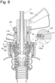
- FIG. 8 is a schematic cross-sectional view schematically showing a state in which the dispense head is attached to the mouth portion of the beverage container.
- FIG. 9 is a schematic cross-sectional view schematically showing how a first pipe can be connected to a second pipe.
- FIG. 10 is a schematic cross-sectional view schematically showing how the first pipe can be connected to the second pipe.
- FIG. 11 is a schematic cross-sectional view schematically showing a state in which a protective cover covers the sealing member.
- FIG. 12 is a schematic cross-sectional view schematically showing a dispense head according to a second embodiment.
- FIG. 13 is a flowchart indicating an example of a method of using a dispense head according to a third embodiment.
- a replaceable component 1 for a dispense head, a dispense head 100 , and a method of using a dispense head 100 will be described with reference to the attached drawings.
- members and portions having the same functions are denoted by the same reference numerals, and repeated descriptions of members and portions denoted by the same reference numerals are omitted.
- FIG. 1 an example of a beverage container 200 to which a dispense head 100 according to some embodiments is to be attached will be explained.
- the beverage container 200 includes a container main body 210 for containing a beverage, a mouth member 220 a , a fitting member F, and a sealing member S arranged between the mouth member 220 a and the fitting member F.
- the container main body 210 is preferably made of metal (for example, made of stainless steel). However, the container main body 210 may be made of non-metal material.
- the mouth member 220 a is preferably made of metal (for example, made of stainless steel). However, the mouth member 220 a may be made of non-metal material.
- the fitting member F is attached to the mouth member 220 a .
- the fitting member F includes an inner member 220 b attached to an inside of the mouth member 220 a , a beverage supply valve V 1 , a gas valve V 2 , a beverage extraction pipe 230 , and a biasing member ( 250 , 260 ).
- a portion of the inner member 220 b that is arranged so as to face the mouth member 220 a is integrated with the mouth member 220 a by a threaded engagement, thus the portion functions as a part of a mouth portion. Therefore, in this specification, the mouth member 220 a and the portion of the inner member 220 b (more specifically, the portion of the inner member 220 b that is arranged so as to face the mouth member 220 a ) are referred to as the mouth portion 220 .
- the inner member 220 b has a recess portion 220 d that receives a second sealing portion 52 described later.
- the inner member 220 b has a second valve seat portion VB 2 .
- the second valve seat portion VB 2 functions as a valve seat portion of the gas valve V 2 .
- the second valve seat portion VB 2 is arranged below the recess portion 220 d.
- a second valve body VA 2 is arranged inside the inner member 220 b (more specifically, arranged inside the second valve seat portion VB 2 ).
- the second valve body VA 2 functions as a valve body of the gas valve V 2 .
- the second valve body VA 2 is an annular member having an opening portion OP in its central portion.
- the opening portion OP of the second valve body VA 2 functions as a beverage outlet 203 for taking out a beverage.
- a recess portion 203 d for receiving a first sealing portion 51 described later is formed.
- a valve seat portion VB 1 of the beverage supply valve V 1 is arranged.
- the beverage extraction pipe 230 is attached to an outer peripheral surface of the second valve body VA 2 .
- the second valve body VA 2 and the beverage extraction pipe 230 are biased upward by a second biasing member 260 .
- a valve body VA 1 is arranged inside the beverage extraction pipe 230 .
- the valve body VA 1 functions as a valve body of the beverage supply valve V 1 .
- the valve body VA 1 is biased upward by a first biasing member 250 .
- beverage container 200 is only an example of the beverage container to which the dispense head 100 according to some embodiments is to be attached.
- the dispense head 100 according to some embodiments may be attached to a beverage container having a structure different from that of the beverage container 200 described above.
- FIG. 2 is a schematic cross-sectional view schematically showing a replaceable component 1 A for a dispense head according to a first embodiment.
- FIGS. 3 and 4 are schematic cross-sectional views schematically showing a state in which a dispense head 100 A is attached to a mouth portion 220 of a beverage container 200 .
- FIG. 3 shows a state in which a beverage supply valve V 1 is in a closed state
- FIG. 4 shows a state in which the beverage supply valve V 1 is in an open state.
- FIG. 5 is an enlarged cross-sectional view of a portion represented by a circle A in FIG. 4 .
- FIG. 6 is a schematic three-view schematically showing an example of a sealing member 5 .
- a schematic plan view is shown on the upper side of FIG. 6
- a schematic side view is shown in the center of FIG. 6
- a schematic bottom view is shown on the lower side of FIG. 6 .
- FIG. 7 is a schematic cross-sectional view schematically showing another example of the sealing member 5 .
- FIG. 8 is a schematic cross-sectional view schematically showing a state in which the dispense head 100 A is attached to the mouth portion 220 of the beverage container 200 .
- FIGS. 9 and 10 are schematic cross-sectional views schematically showing how a first pipe 3 can be connected to a second pipe 8 . Note that FIG.
- FIG. 9 shows a state before the first pipe 3 and the second pipe 8 are connected
- FIG. 10 shows a state after the first pipe 3 and the second pipe 8 are connected
- FIG. 11 is a schematic cross-sectional view schematically showing a state in which a protective cover 7 covers the sealing member 5 .
- a replaceable component 1 A for a dispense head includes a first pipe 3 , a pressing portion 4 , and a sealing member 5 .
- the first pipe 3 is a member arranged so as to pass through an inside of the dispense head 100 A (more specifically, an inside of a plunger member 120 of the dispense head 100 A).
- the first pipe 3 is arranged inside the dispense head 100 A (more specifically, inside the plunger member 120 ) and a beverage flows through the inside of the first pipe 3 , the beverage does not adhere to an inner surface of the dispense head 100 A (more specifically, an inner surface of the plunger member 120 ).
- the first pipe 3 may be composed of one part or may be composed of an assembly of a plurality of parts.
- the first pipe 3 is made of, for example, a resin.
- the first pipe 3 is preferably a rigid pipe, but the first pipe 3 may be a flexible pipe.
- the first pipe 3 is formed by, for example, injection molding.
- the pressing portion 4 can press a valve body VA 1 of a beverage supply valve V 1 in a beverage container 200 .
- the valve body VA 1 is separated from a valve seat portion VB 1 of the beverage supply valve V 1 (see FIG. 4 ). In this way, the beverage in a container main body 210 of the beverage container 200 can be taken out to the first pipe 3 via the beverage supply valve V 1 .
- the pressing portion and the first pipe 3 are integrally formed. More specifically, the pressing portion 4 is constituted by a first end portion 31 of the first pipe 3 . Alternatively, the pressing portion 4 and the first pipe 3 may be separate bodies. In this case, a part constituting the pressing portion 4 is attached to the first pipe 3 .
- the pressing portion 4 is made of, for example, a resin.
- the pressing portion 4 is preferably made of a hard resin (in other words, the pressing portion 4 is preferably made of a resin that is not substantially deflectable).
- the sealing member 5 includes a first sealing portion 51 and a membrane 53 connected to the first sealing portion 51 .
- the sealing member 5 is separately provided from the first pipe 3 and the pressing portion 4 , and the sealing member 5 is attached to the first pipe 3 .
- the first sealing portion 51 is contactable with a beverage outlet 203 of the beverage container 200 .
- the beverage outlet 203 is constituted by an opening portion OP of the second valve body VA 2 that constitutes a part of the gas valve V 2 .
- the first sealing portion 51 may be made of a flexible resin (in other words, a soft resin), or may be made of rubber.
- the membrane 53 inhibits the beverage from adhering to the dispense head 100 A.
- the membrane 53 is arranged on an outer side of the first sealing portion 51 .
- the membrane 53 may be made of a flexible resin (in other words, a soft resin), or may be made of rubber.
- the membrane 53 and the first sealing portion 51 are preferably formed by integral molding.
- the beverage on the pressing portion 4 may be scattered toward the dispense head 100 A.
- the replaceable component 1 A according to the first embodiment even when the beverage is scattered toward the dispense head 100 A (particularly, toward a lower surface of the dispense head 100 A), the membrane 53 inhibits the beverage from adhering to the dispense head 100 A.
- the replaceable component 1 A for a dispense head that comes in contact with the beverage, and the beverage is substantially prevented from coming in contact with the dispense head 100 A. Therefore, frequency of cleaning the dispense head 100 A can be reduced. Further, even when the beverage adheres to the dispense head 100 A, the replaceable component 1 A for a dispense head (more specifically, the first pipe 3 and the sealing member 5 ) prevents the adhered beverage from being mixed into the beverage in the beverage container 200 .
- a beverage supply flow path in a clean state can be reformed by just removing the replaceable component 1 A for a dispense head which has been attached to the dispense head 100 A and just attaching a new replaceable component for a dispense head to the dispense head 100 A.
- the first sealing portion 51 fits into a recess portion 203 d of the beverage outlet 203 . Due to this fitting, a bottom surface 51 b of the first sealing portion 51 comes in contact with a bottom surface 203 t of the recess portion 203 d and an outer peripheral surface 51 u of the first sealing portion 51 comes in contact with an inner peripheral surface 203 n of the recess portion 203 d.
- the sealing member 5 includes a second sealing portion 52 contactable with a mouth portion 220 of the beverage container 200 .
- a recess portion 220 d for receiving the second sealing portion 52 is formed in the mouth portion 220 (more specifically, formed in an inner member 220 b ).
- a bottom surface of the second sealing portion 52 comes in contact with a bottom surface of the recess portion 220 d and an outer peripheral surface of the second sealing portion 52 comes in contact with an inner peripheral surface of the recess portion 220 d.
- the mouth portion 220 is sealed by the second sealing portion 52 . In this way, it is possible to prevent a fluid such as a gas from leaking from a gap between the dispense head 100 A and the mouth portion 220 .
- the membrane 53 deforms from a first state (see FIG. 3 ) to a second state (see FIG. 4 ). Since the membrane 53 is deformable between the first state and the second state, the membrane 53 can follow a movement of the pressing portion 4 .
- the first state is, for example, a state in which the membrane 53 is loosened
- the second state is, for example, a state in which the membrane 53 is stretched (in other words, a state in which tension is acting on the membrane 53 ).
- the membrane 53 is formed of, for example, a flexible resin or rubber.
- the membrane 53 is preferably integrally molded with the first sealing portion 51 and/or the second sealing portion 52 .
- the membrane 53 is arranged between the first sealing portion 51 and the second sealing portion 52 .
- the membrane 53 arranged between the first sealing portion 51 and the second sealing portion 52 inhibits the beverage from adhering to the dispense head 100 A (particularly, the lower surface of the dispense head 100 A).
- a state of the membrane 53 (in other words, a shape of the membrane 53 ) is defined by a relative position of the first sealing portion 51 with respect to the second sealing portion 52 . More specifically, when the first sealing portion 51 moves away from the second sealing portion 52 (moves downward in the example shown in FIG. 3 ), the state of the membrane 53 is changed from the above-mentioned first state (for example, the loosened state) to the above-mentioned second state (for example, the stretched state).
- the thickness of the first sealing portion 51 is larger than the thickness of the membrane 53 .
- the thickness of the first sealing portion 51 may be about the same as the thickness of the membrane 53 .
- the first sealing portion 51 may be constituted by an inner side portion of the membrane 53 .
- the thickness of the second sealing portion 52 is larger than the thickness of the membrane 53 .
- the thickness of the second sealing portion 52 may be about the same as the thickness of the membrane 53 .
- the second sealing portion 52 may be constituted by an outer side portion of the membrane 53 .
- a gas passage hole 53 h is formed in the sealing member 5 (more specifically, formed in the membrane 53 ).
- the gas passage hole 53 h is used to introduce a gas (for example, carbon dioxide gas) supplied from the outside of the dispense head 100 A into the beverage container 200 (more specifically, into the container main body 210 of the beverage container 200 ).
- a gas for example, carbon dioxide gas
- the gas supplied into the dispense head 100 A via a dispense head main body 110 of the dispense head 100 A is introduced into the container main body 210 of the beverage container 200 via the gas passage hole 53 h and the gas valve V 2 in an open state.
- the sealing member 5 (more specifically, the membrane 53 ) has six gas passage holes 53 h .
- the sealing member 5 (more specifically, the membrane 53 ) may have only one gas passage hole or two, three, four, five, or seven or more gas passage holes 53 h.
- the first sealing portion 51 has a ring shape in a plan view (or a bottom view).
- the second sealing portion 52 has a ring shape in a plan view (or a bottom view).
- the membrane 53 has a ring shape in a plan view (or a bottom view).
- an outer peripheral edge of the first sealing portion 51 is connected to an inner peripheral edge of the membrane 53 .
- an outer peripheral edge of the membrane 53 is connected to an inner peripheral edge of the second sealing portion 52 .
- the first sealing portion 51 has a second engaging portion 512 that engages with a first engaging portion 34 of the first pipe 3 .
- the second engaging portion 512 includes an inner peripheral surface side engaging portion 512 a formed on an inner peripheral surface of the first sealing portion 51 .
- the second engaging portion 512 may include an upper surface side engaging portion 512 b formed on an upper surface of the first sealing portion 51 .
- the first engaging portion 34 is an engaging recess 34 a
- the second engaging portion 512 is an engaging protrusion.
- the first engaging portion 34 may be an engaging protrusion and the second engaging portion 512 may be an engaging recess.
- the second sealing portion 52 has a fourth engaging portion 522 that engages with a third engaging portion 64 of a held portion 6 held by the dispense head main body 110 .
- the fourth engaging portion 522 includes an inner peripheral surface side engaging portion 522 a formed on an inner peripheral surface of the second sealing portion 52 .
- the fourth engaging portion 522 may include an upper surface side engaging portion formed on an upper surface of the second sealing portion 52 , or may include an outer peripheral surface side engaging portion formed on an outer peripheral surface of the second sealing portion 52 .
- the third engaging portion 64 is an engaging recess
- the fourth engaging portion 522 is an engaging protrusion.
- the third engaging portion 64 may be an engaging protrusion and the fourth engaging portion 522 may be an engaging recess.
- the gas passage hole 53 h is an always open hole that is always open.
- the gas passage hole 53 h may be configured to close in an initial state (in other words, in a state in which the pressing portion 4 is separated from the valve body VA 1 of the beverage supply valve V 1 ), or may be configured to close in a state in which the membrane 53 is loosened.
- the gas passage hole 53 h is constituted by a slit SL formed in the membrane 53 .
- the gas passage hole 53 h can change states from a closed state to an open state. More specifically, when the first sealing portion 51 moves toward the beverage supply valve V 1 together with the pressing portion 4 , the membrane 53 deforms from the first state (more specifically, the loosened state) to the second state (more specifically, the stretched state). By deforming the membrane 53 into the second state, in other words, by stretching the membrane 53 , the gas passage hole 53 h is opened (see FIG. 7 ( b ) ).
- the gas passage hole 53 h is closed when the pressing portion 4 moves away from the valve body VA 1 of the beverage supply valve V 1 (more specifically, when the membrane 53 is returning to the first state from the second state). In this case, the beverage on the pressing portion 4 etc. is certainly prevented from moving to the dispense head 100 A side through the gas passage hole 53 h . More specifically, in the membrane 53 in the first state (see FIG. 7 ( a ) ), the gas passage hole 53 h is closed. Therefore, the membrane 53 in the first state can prevent the beverage more certainly from adhering to the dispense head 100 A (particularly, the lower surface of the dispense head 100 A).
- the gas passage hole 53 h is opened by moving the pressing portion 4 toward the valve body VA 1 .
- the gas passage hole 53 h may be opened by supplying the gas to the dispense head 100 A (more specifically, to a gas inlet hole 110 h of the dispense head 100 A). More specifically, in a state in which the gas is not supplied to the dispense head 100 A (more specifically, to the gas inlet hole 110 h ), the gas passage hole 53 h may be closed even when the pressing portion 4 moves toward the valve body VA 1 , and the gas passage hole 53 h may be opened when the gas is supplied to the dispense head 100 A.
- Such a configuration can be feasible, for example, by arranging a check valve on the sealing member 5 (for example, the membrane 53 ).
- the check valve is opened, for example, when the gas is supplied to the dispense head 100 A and the pressure in a space above the sealing member 5 increases.
- the membrane 53 can prevent the beverage from adhering to the dispense head 100 A (particularly, the lower surface of the dispense head 100 A).
- the replaceable component 1 A for a dispense head includes the held portion 6 held by the dispense head main body 110 .
- the held portion 6 is, for example, made of a resin.
- the held portion 6 is, for example, formed by injection molding.
- the held portion 6 and the first pipe 3 are separate bodies.
- the held portion 6 may be integrally molded with the first pipe 3 (for example, with a flange 35 of the first pipe 3 ).
- the held portion 6 is held by, for example, a recess 110 d formed on a lower surface of the dispense head main body 110 .
- the held portion 6 may be held by an engaging portion 117 formed on the dispense head main body 110 (more specifically, a lower end portion of the dispense head main body 110 ).
- the held portion 6 is held by the dispense head main body 110 .
- a sealing ring (more specifically, a first sealing ring S 1 ) is arranged on an upper surface of the held portion 6 .
- the sealing ring prevents a fluid such as a gas from leaking from between the upper surface of the held portion 6 and a lower surface of the dispense head main body 110 . If there is no possibility of fluid leakage etc., the sealing ring may be omitted.
- the held portion 6 includes the engaging portion (the third engaging portion 64 ) that engages with the engaging portion (the fourth engaging portion 522 ) of the second sealing portion 52 . Therefore, the second sealing portion 52 is supported by the dispense head main body 110 via the held portion 6 .
- first pipe 3 An example of the first pipe 3 will be described in more detail with reference to FIGS. 2 and 3 , etc.
- a first end portion 31 an end portion on the side where the pressing portion 4 is arranged
- a second end portion 32 an end portion on an opposite side opposed to the side where the pressing portion 4 is arranged
- the beverage supplied from the beverage container 200 to the first pipe 3 flows from the first end portion 31 to the second end portion 32 .
- a direction from the first end portion 31 to the second end portion 32 may be referred to as an upward direction
- a direction from the second end portion 32 to the first end portion 31 may be referred to as a downward direction.
- the length of the first pipe 3 is preferably longer than the length of a plunger member 120 of the dispense head 100 A.
- the length of the first pipe 3 is, for example, 5 cm or more, or 10 cm or more.
- an inner diameter of the first pipe 3 decreases from the first end portion 31 toward the second end portion 32 .
- the inner diameter of the first pipe 3 may be constant.
- an opening OP 1 to introduce the beverage from the outside of the first pipe 3 to the inside of the first pipe 3 is formed.
- the maximum outer diameter of a portion of the first pipe 3 arranged in the plunger member 120 is set to a size that fits with the plunger member 120 .
- an outer surface of the first pipe 3 and an inner surface of the plunger member 120 can be fitted together.
- the first pipe 3 includes the flange 35 extending in a direction away from a longitudinal central axis C 1 of the first pipe 3 .
- the flange 35 is integrally molded with the first pipe 3 and is arranged on the outer peripheral surface of the first pipe 3 .
- the flange 35 and a first pipe main body 30 may be formed separately, and the flange 35 may be attached to the first pipe main body 30 .
- the flange 35 is made of, for example, a resin.
- the flange 35 is preferably made of a hard resin (in other words, the flange 35 is preferably made of a resin that is not substantially deflectable).
- a lower surface of the flange 35 is in contact with the upper surface of the first sealing portion 51 .
- the flange 35 prevents the first sealing portion 51 from moving upward beyond the flange 35 .
- an upward force acts on the first sealing portion 51 due to the contact.
- the flange 35 presses the first sealing portion 51 downward. In this way, the first sealing portion 51 is sandwiched between the beverage outlet 203 and the flange 35 , and the movement of the first sealing portion 51 is prevented.
- the first engaging portion 34 that engages with the second engaging portion 512 of the sealing member 5 is formed on the lower surface of the flange 35 .
- the first engaging portion 34 is the engaging recess 34 a .
- the first engaging portion 34 may be an engaging protrusion.
- an upper surface of the flange 35 is in contact with a lower surface of the plunger member 120 .
- the upper surface of the flange 35 functions as a pressed surface to be pressed by the plunger member 120 . More specifically, when the plunger member 120 moves downward relative to the dispense head main body 110 , the plunger member 120 presses the flange 35 . In this way, the flange 35 moves downward together with the plunger member 120 . When the flange 35 moves downward, the flange 35 presses the upper surface of the first sealing portion 51 downward. In this way, the first sealing portion 51 moves downward together with the flange 35 and the plunger member 120 .
- a sealing ring (more specifically, a second sealing ring S 2 ) is arranged on the upper surface of the flange 35 .
- the sealing ring prevents a fluid such as a gas from leaking from between the upper surface of the flange 35 and the lower surface of the plunger member 120 . If there is no possibility of fluid leakage etc., the sealing ring may be omitted.
- a reinforcing rib 37 extending in a direction parallel to the longitudinal central axis C 1 of the first pipe 3 is arranged on the outer surface of the first pipe 3 .
- the presence of the reinforcing rib 37 improves the rigidity of the first pipe 3 .
- the first pipe 3 preferably includes an end portion connectable to a second pipe 8 and a cover portion 33 arranged to cover the end portion.
- the end portion connectable to the second pipe 8 is the second end portion 32 of the first pipe 3 .
- a sealing ring (more specifically, a third sealing ring S 3 ) is arranged on an outer peripheral surface of the second end portion 32 . The sealing ring prevents the beverage from leaking from between the first pipe 3 and the second pipe 8 .
- the cover portion 33 prevents an operator's hand from touching the end portion (in other words, the second end portion 32 ) connectable to the second pipe 8 .
- an upper end 33 u of the cover portion 33 is located above an upper end 32 u of the second end portion 32 .
- the upper end 32 u of the second end portion 32 is hidden by the cover portion 33 . In this case, the operator's hand is effectively prevented from touching the second end portion 32 .
- the cover portion 33 and the first pipe main body 30 are separate bodies, and the cover portion 33 is attached to the first pipe main body 30 .
- the cover portion 33 may be integrally molded with the first pipe main body 30 .
- the cover portion 33 is a tubular body having a tubular shape. Further, in the example shown in FIG. 9 , the cover portion 33 constitutes an outer cylinder arranged outside the second end portion 32 , and the second end portion 32 constitutes an inner cylinder arranged inside the cover portion 33 .
- the cover portion 33 is formed with an engaging portion 332 that can engage with an engaging portion 82 of the second pipe 8 .
- the engaging portion 332 that can engage with the engaging portion 82 of the second pipe 8 may be formed at the second end portion 32 of the first pipe 3 .
- the replaceable component 1 A for a dispense head includes a protective cover 7 capable of covering the sealing member 5 (more specifically, a lower surface of the sealing member 5 ).
- the protective cover 7 collectively covers a lower surface of the first sealing portion 51 , a lower surface of the membrane 53 , and a lower surface of the second sealing portion 52 .
- the protective cover 7 is preferably attached to the sealing member 5 at an arbitrary timing after the sealing member 5 is manufactured. Further, the protective cover 7 is preferably removed from the sealing member 5 after the first pipe 3 is arranged to pass through the inside of the dispense head 100 A (more specifically, the inside of the plunger member 120 of the dispense head 100 A).
- the protective cover 7 collectively covers the lower surface of the sealing member 5 and the pressing portion 4 . Therefore, the protective cover 7 prevents the operator's hand from touching the lower surface of the sealing member 5 , and also prevents the operator's hand from touching the pressing portion 4 . In this way, germs and the like are prevented from adhering to the sealing member 5 or the pressing portion 4 .
- the protective cover 7 may be a flexible cover or a rigid cover.
- FIG. 12 is a schematic cross-sectional view schematically showing a dispense head 100 A according to a second embodiment.
- a dispense head 100 A according to the second embodiment is a dispense head to which the replaceable component 1 A for a dispense head according to the first embodiment can be attached.
- the dispense head 100 A includes a dispense head main body 110 , a plunger member 120 , and an operating member 130 .
- the dispense head main body 110 includes an attachment portion 111 for attaching the dispense head main body 110 to the beverage container 200 , a gas inlet hole 110 h for introducing a gas (for example, carbon dioxide) from the outside of the dispense head main body 110 into the inside of the dispense head main body 110 , a hole portion 110 p that receives the plunger member 120 in such a way that the plunger member 120 can slidably move relative to the hole portion 110 p , and a connecting portion 113 for connecting the operating member 130 to the dispense head main body 110 .
- a gas inlet hole 110 h for introducing a gas (for example, carbon dioxide) from the outside of the dispense head main body 110 into the inside of the dispense head main body 110
- a hole portion 110 p that receives the plunger member 120 in such a way that the plunger member 120 can slidably move relative to the hole portion 110 p
- a connecting portion 113 for connecting the operating member 130 to the disp
- a recess 110 d that can receive a part of the replaceable component 1 A for a dispense head (for example, a part of the held portion 6 described above) may be formed.
- the dispense head main body 110 may include a engaging portion 117 that can engage with a part of the replaceable component 1 A for a dispense head (for example, the held portion 6 described above).
- the dispense head main body 110 is made of, for example, metal (more specifically, made of stainless steel).
- the plunger member 120 is formed with a through hole 120 h into which the first pipe 3 constituting a part of the replaceable component 1 A for a dispense head can be inserted. Further, by pressing the first pipe 3 (more specifically, the flange 35 of the first pipe 3 ) downward, the plunger member 120 can move the first sealing portion 51 and the pressing portion 4 , which constitute parts of the replaceable component 1 A for a dispense head, downward.
- the plunger member 120 is made of, for example, metal (more specifically, made of stainless steel).
- the operating member 130 is a member that operates the plunger member 120 such that the plunger member 120 moves relative to the dispense head main body 110 .
- the operating member 130 is an operation lever that can swing around a rotational axis AX arranged in the dispense head main body 110 .
- the plunger member 120 moves downward.
- the dispense head main body 110 may be provided with an engaging portion 119 that engages with the operating member 130 (more specifically, the operation lever).
- the engaging portion 119 engages with the operating member 130 . This engagement prevents the operating member 130 from being unintentionally operated in the second operating direction (more specifically, upward), and prevents the plunger member 120 from being unintentionally moved upward.
- FIG. 13 is a flowchart indicating an example of a method of using a dispense head 100 according to a third embodiment.
- a replaceable component 1 for a dispense head used in a method of using a dispense head according to a third embodiment may be the replaceable component 1 A for a dispense head according to the first embodiment, or may be another replaceable component for a dispense head.
- a dispense head 100 used in the method of using a dispense head according to the third embodiment may be the dispense head 100 A according to the second embodiment, or may be another dispense head.
- a first step ST 1 the replaceable component 1 for a dispense head is attached to the dispense head 100 .
- the first step ST 1 is a first attaching step.
- the first step ST 1 (the first attaching step) is executed, for example, by inserting a first pipe 3 of the replaceable component 1 for a dispense head into a plunger member 120 of the dispense head 100 .
- the first step ST 1 (the first attaching step) is preferably executed by inserting the first pipe 3 into the plunger member 120 in a direction from a lower end of the plunger member 120 toward an upper end of the plunger member 120 .
- the first step ST 1 may include a holding step of holding a part of the replaceable component 1 for a dispense head (for example, a held portion 6 ) by a dispense head main body 110 .
- the holding step may include fitting (for example, see FIG. 8 ) a lower end portion of the dispense head main body 110 (for example, a recess 110 d formed on a lower surface of the dispense head main body 110 ) and a part of the replaceable component 1 for a dispense head (for example, the held portion 6 ).
- the holding step may include engaging (for example, see FIG. 8 ) an engaging portion 117 formed at a lower end portion of the dispense head main body 110 and a part of the replaceable component 1 for a dispense head (for example, the held portion 6 ).
- a second end portion 32 of the first pipe 3 may be connected to a second pipe 8 (for example, see FIG. 10 ).
- the second pipe 8 may be a part of a replaceable component for a beverage pouring portion, or may be another part.
- a protective cover 7 may be removed from a sealing member 5 (for example, see the arrow B in FIG. 11 ).
- the dispense head 100 is attached to a beverage container 200 .
- the second step ST 2 is a second attaching step.
- the second step ST 2 (the second attaching step) is executed, for example, by moving the dispense head 100 , to which the replaceable component 1 for a dispense head is attached, downward toward the beverage container 200 and then rotating the dispense head 100 relative to a mouth portion 220 of the beverage container 200 .
- an attachment portion 111 of the dispense head 100 is attached to the mouth portion 220 (more specifically, an inner member 220 b ) of the beverage container 200 .
- a second sealing portion 52 of the sealing member 5 comes in contact with the mouth portion 220 (more specifically, the inner member 220 b ). In this way, the mouth portion 220 (more specifically, the inner member 220 b ) is sealed by the second sealing portion 52 .
- the third step ST 3 is a first moving step.
- the third step ST 3 (the first moving step) is executed, for example, by operating an operating member 130 in a first operating direction (for example, downward).
- the plunger member 120 By executing the third step ST 3 (the first moving step), the plunger member 120 (more specifically, a lower end portion of the plunger member 120 ) presses the first pipe 3 (more specifically, a flange 35 ).
- a first sealing portion 51 of the sealing member 5 is arranged on an outer peripheral surface of the first pipe 3 . Therefore, by executing the third step ST 3 (the first moving step), the first sealing portion 51 moves downward. The first sealing portion 51 moving downward comes in contact with a beverage outlet 203 . In this way, the beverage outlet 203 is sealed by the first sealing portion 51 . After the first sealing portion 51 comes in contact with the beverage outlet 203 , by moving the plunger member 120 and the first pipe 3 downward further, the first sealing portion 51 presses a second valve body VA 2 (that is, a valve body of a gas valve V 2 ), which constitutes the beverage outlet 203 , downward. In this way, the gas valve V 2 is opened.
- a second valve body VA 2 that is, a valve body of a gas valve V 2
- a gas introduced into the dispense head main body 110 through a gas inlet hole 110 h is supplied into a container main body 210 of the beverage container 200 . It is preferable that the gas is supplied from the inside of the dispense head main body 110 to the inside of the container main body 210 through a gas passage hole 53 h of the sealing member 5 .
- a pressing portion 4 is arranged at a lower end portion of the first pipe 3 . Therefore, by executing the third step ST 3 (the first moving step), the pressing portion 4 moves downward.
- the beverage supply valve V 1 is opened.
- the beverage in the container main body 210 is taken out to the first pipe 3 via a beverage extraction pipe 230 in the beverage container 200 , the beverage supply valve V 1 , and an opening OP 1 of the first pipe 3 .
- a membrane 53 of the sealing member 5 deforms from a first state (see FIG. 3 ) to a second state (see FIG. 4 ).
- a part of the sealing member 5 held by the dispense head main body 110 more specifically, with a part of the sealing member 5 held between the dispense head main body 110 and the mouth portion 220
- another part of the sealing member 5 (more specifically, the first sealing portion 51 ) can be moved downward.
- a fourth step ST 4 the plunger member 120 of the dispense head 100 is moved upward.
- the fourth step ST 4 is a second moving step.
- the fourth step ST 4 (the second moving step) is executed, for example, by operating the operating member 130 in a second operating direction (for example, upward).
- the first pipe 3 and the first sealing portion 51 moves upward.
- the first pipe 3 and the first sealing portion 51 moves upward as the plunger member 120 of the dispense head 100 moves upward.
- the first pipe 3 and the first sealing portion 51 moves upward when the valve body VA 1 of the beverage supply valve V 1 moves upward by a biasing force of a first biasing member 250 (see FIG. 4 ), or when the second valve body VA 2 of the gas valve V 2 moves upward by a biasing force of a second biasing member 260 (see FIG. 4 ).
- valve body VA 1 moves upward due to the biasing force of the first biasing member 250 , the valve body VA 1 presses the pressing portion 4 arranged at the lower end portion of the first pipe 3 , upward. In this way, the first pipe 3 and the pressing portion 4 moves upward. As the valve body VA 1 moves upward, the valve body VA 1 comes in contact with a valve seat portion VB 1 . In this way, the beverage supply valve V 1 is closed.
- the second valve body VA 2 moves upward due to the biasing force of the second biasing member 260 , the second valve body VA 2 presses the first sealing portion 51 upward. In this way, the first sealing portion 51 moves upward together with the first pipe 3 and the pressing portion 4 . As the second valve body VA 2 moves upward, the second valve body VA 2 comes in contact with a second valve seat portion VB 2 . In this way, the gas valve V 2 is closed.
- the membrane 53 of the sealing member 5 returns from the second state (see FIG. 4 ) to the first state (see FIG. 3 ). In this way, with the part of the sealing member 5 held by the dispense head main body 110 (more specifically, with the part of the sealing member 5 held between the dispense head main body 110 and the mouth portion 220 ), it is possible to move another part of the sealing member 5 (more specifically, the first sealing portion 51 ) upward.
- a fifth step ST 5 the dispense head 100 is removed from the beverage container 200 .
- the fifth step ST 5 is a first removal step.
- the fifth step ST 5 (the first removal step) is executed, for example, by rotating the dispense head 100 , to which the replaceable component 1 for a dispense head is attached, relative to the mouth portion 220 of the beverage container 200 and then moving the dispense head 100 upward relative to the beverage container 200 .
- the attachment portion 111 of the dispense head 100 is detached from the mouth portion 220 (more specifically, the inner member 220 b ) of the beverage container 200 .
- the second end portion 32 of the first pipe 3 may be detached from the second pipe 8 .
- the replaceable component 1 for a dispense head is removed from the dispense head 100 .
- the sixth step ST 6 is a second removal step.
- the sixth step ST 6 (the second removal step) is executed, for example, by taking out the first pipe 3 of the replaceable component 1 for a dispense head from the plunger member 120 of the dispense head 100 .
- the sixth step ST 6 (the second removal step) is preferably executed by pulling out the first pipe 3 from the plunger member 120 in a direction from the upper end of the plunger member 120 toward the lower end of the plunger member 120 .
- a second replaceable component for a dispense head which is different from the replaceable component 1 for a dispense head, is attached to the dispense head 100 .
- the second replaceable component for a dispense head is preferably a component of the same type as the above-mentioned replaceable component 1 for a dispense head (more specifically, the second replaceable component preferably has the same shape as the replaceable component 1 for a dispense head).
- the seventh step ST 7 is the same as the first step ST 1 described above, except that the “replaceable component 1 for a dispense head” is replaced with the “second replaceable component for a dispense head”. Therefore, a repetitive description of the seventh step ST 7 will be omitted.
- an eighth step ST 8 the dispense head 100 , to which the second replaceable component for a dispense head is attached, is attached to a second beverage container different from the beverage container 200 described above.
- the eighth step ST 8 is the same as the second step ST 2 described above, except that the “replaceable component 1 for a dispense head” and the “beverage container 200 ” are replaced with the “second replaceable component for a dispense head” and the “second beverage container”, respectively. Therefore, a repetitive description of the eighth step ST 8 will be omitted.
- the membrane 53 inhibits the beverage from adhering to the dispense head 100 .
- a lower surface of the dispense head 100 is covered with the membrane 53 during the execution of the third step ST 3 (the first moving step) and the fourth step (the second moving step). In this case, it is possible to inhibit the beverage from adhering to the lower surface of the dispense head 100 during the execution of the third step ST 3 (the first moving step) and the fourth step (the second moving step).
- the lower surface of the dispense head 100 is covered with the membrane 53 during the execution of the fifth step ST 5 (the first removal step). In this case, it is possible to inhibit the beverage from adhering to the lower surface of the dispense head 100 during the execution of the fifth step ST 5 (the first removal step).
- a clean beverage supply flow path can be reformed simply by removing the replaceable component 1 for a dispense head, which has been attached to the dispense head 100 , and attaching the second replaceable component for a dispense head to the dispense head 100 .
- 1 , 1 A replaceable component for a dispense head 3 first pipe, 4 pressing portion, 5 sealing member, 6 held portion, 7 protective cover, 8 second pipe, 30 first pipe main body, 31 first end portion, 32 second end portion, 32 u upper end, 33 cover portion, 33 u upper end, 34 first engaging portion, 34 a engaging recess, 35 flange, 37 reinforcing rib, 51 first sealing portion, 51 b bottom surface, 51 u outer peripheral surface, 52 second sealing portion, 53 membrane, 53 h gas passage hole, 61 engaging portion, 64 third engaging portion, 82 engaging portion, 100 , 100 A dispense head, 110 dispense head main body, 110 d recess, 110 h gas inlet hole, 110 p hole portion, 111 attachment portion, 113 connecting portion, 117 engaging portion, 119 engaging portion, 120 plunger member, 120 h through hole, 130 operating member, 200 beverage container, 203 beverage outlet, 203 d recess portion, 203 n inner peripheral surface, 203 t bottom surface, 210
Landscapes
- Devices For Dispensing Beverages (AREA)
Abstract
Description
Claims (17)
Applications Claiming Priority (3)
| Application Number | Priority Date | Filing Date | Title |
|---|---|---|---|
| JP2020007126A JP2021113078A (en) | 2020-01-20 | 2020-01-20 | Replacement part for dispense head, dispense head and application method of dispense head |
| JP2020-007126 | 2020-01-20 | ||
| PCT/JP2020/046042 WO2021149391A1 (en) | 2020-01-20 | 2020-12-10 | Replacement component for dispensing head, dispensing head, and method for using dispensing head |
Publications (2)
| Publication Number | Publication Date |
|---|---|
| US20220332561A1 US20220332561A1 (en) | 2022-10-20 |
| US11939201B2 true US11939201B2 (en) | 2024-03-26 |
Family
ID=76992228
Family Applications (1)
| Application Number | Title | Priority Date | Filing Date |
|---|---|---|---|
| US17/762,445 Active 2040-12-26 US11939201B2 (en) | 2020-01-20 | 2020-12-10 | Replaceable component for a dispense head, a dispence head, and a method of using a dispense head |
Country Status (6)
| Country | Link |
|---|---|
| US (1) | US11939201B2 (en) |
| EP (1) | EP4095088A4 (en) |
| JP (1) | JP2021113078A (en) |
| CN (1) | CN114650963B (en) |
| AU (1) | AU2020425255A1 (en) |
| WO (1) | WO2021149391A1 (en) |
Families Citing this family (1)
| Publication number | Priority date | Publication date | Assignee | Title |
|---|---|---|---|---|
| WO2023282006A1 (en) | 2021-07-07 | 2023-01-12 | キヤノン株式会社 | Conductive composition, method for producing same, method for recording conductive image, and conductive image |
Citations (6)
| Publication number | Priority date | Publication date | Assignee | Title |
|---|---|---|---|---|
| US5090599A (en) | 1991-02-28 | 1992-02-25 | Johnson Enterprises, Inc. | Seal for a beverage tap |
| US5145096A (en) * | 1991-08-08 | 1992-09-08 | Johnson Enterprises, Inc. | Slide-on tap for a beverage container |
| US20100308084A1 (en) * | 2007-09-20 | 2010-12-09 | Micro Matic A/S | Dispenser Head for Connection with an Extractor Device Mounted in a Beverage Container |
| WO2013000932A1 (en) | 2011-06-28 | 2013-01-03 | Micro Matic A/S | Beverage dispensing system |
| JP2019018860A (en) | 2017-07-11 | 2019-02-07 | アサヒビール株式会社 | Beverage discharging device |
| JP2019142581A (en) | 2018-02-23 | 2019-08-29 | テクノアート有限会社 | Method for fixing inner bag assembly to stainless steel beverage storage container through fixing member, method for taking out beverage, and inner bag assembly |
Family Cites Families (7)
| Publication number | Priority date | Publication date | Assignee | Title |
|---|---|---|---|---|
| US4291821A (en) * | 1979-10-04 | 1981-09-29 | The Perlick Company, Inc. | Keg tapping system unit and valve interlock |
| CN1068545A (en) * | 1988-05-17 | 1993-02-03 | 伊索沃思有限公司 | Carbonation apparatus |
| CN2827948Y (en) * | 2005-03-08 | 2006-10-18 | 深圳市深安电器有限公司 | Beverage cylinder for preventing secondary pollution |
| JP3914560B1 (en) * | 2006-01-31 | 2007-05-16 | 東京応化工業株式会社 | Fittings for fluid containers |
| US8646660B2 (en) * | 2009-04-01 | 2014-02-11 | Thomas W. Bates | Reusable beer keg |
| GB2559394B (en) * | 2017-02-03 | 2020-04-15 | Petainer Large Container Ip Ltd | Closure with venting system |
| JP6808030B2 (en) * | 2017-05-19 | 2021-01-06 | サントリーホールディングス株式会社 | How to clean the dispense head and the beverage discharge path using it |
-
2020
- 2020-01-20 JP JP2020007126A patent/JP2021113078A/en active Pending
- 2020-12-10 EP EP20915050.7A patent/EP4095088A4/en active Pending
- 2020-12-10 AU AU2020425255A patent/AU2020425255A1/en active Pending
- 2020-12-10 US US17/762,445 patent/US11939201B2/en active Active
- 2020-12-10 WO PCT/JP2020/046042 patent/WO2021149391A1/en unknown
- 2020-12-10 CN CN202080076840.XA patent/CN114650963B/en active Active
Patent Citations (7)
| Publication number | Priority date | Publication date | Assignee | Title |
|---|---|---|---|---|
| US5090599A (en) | 1991-02-28 | 1992-02-25 | Johnson Enterprises, Inc. | Seal for a beverage tap |
| US5145096A (en) * | 1991-08-08 | 1992-09-08 | Johnson Enterprises, Inc. | Slide-on tap for a beverage container |
| US20100308084A1 (en) * | 2007-09-20 | 2010-12-09 | Micro Matic A/S | Dispenser Head for Connection with an Extractor Device Mounted in a Beverage Container |
| WO2013000932A1 (en) | 2011-06-28 | 2013-01-03 | Micro Matic A/S | Beverage dispensing system |
| JP2014518184A (en) | 2011-06-28 | 2014-07-28 | マイクロ・マティック・エー/エス | Beverage dispensing system |
| JP2019018860A (en) | 2017-07-11 | 2019-02-07 | アサヒビール株式会社 | Beverage discharging device |
| JP2019142581A (en) | 2018-02-23 | 2019-08-29 | テクノアート有限会社 | Method for fixing inner bag assembly to stainless steel beverage storage container through fixing member, method for taking out beverage, and inner bag assembly |
Non-Patent Citations (2)
| Title |
|---|
| English translation of Office Action dated Dec. 12, 2023 in Japanese Application No. 2020-007126. |
| International Search Report dated Jan. 19, 2021 in International (PCT) Application No. PCT/JP2020/046042. |
Also Published As
| Publication number | Publication date |
|---|---|
| CN114650963A (en) | 2022-06-21 |
| WO2021149391A1 (en) | 2021-07-29 |
| EP4095088A1 (en) | 2022-11-30 |
| AU2020425255A1 (en) | 2022-07-21 |
| EP4095088A4 (en) | 2024-02-28 |
| CN114650963B (en) | 2024-05-17 |
| US20220332561A1 (en) | 2022-10-20 |
| JP2021113078A (en) | 2021-08-05 |
Similar Documents
| Publication | Publication Date | Title |
|---|---|---|
| US6644510B2 (en) | Bag-in-box container and faucet | |
| US9156569B2 (en) | Pediatric dosing dispenser | |
| CN105480928B (en) | Fuel dispensing nozzle | |
| US8783521B2 (en) | Container for eye drops | |
| US8602270B2 (en) | Connector for a fluid tank | |
| US11939201B2 (en) | Replaceable component for a dispense head, a dispence head, and a method of using a dispense head | |
| JP5476351B2 (en) | Cap unit for puncture repair | |
| JP2003321038A (en) | Pouring container | |
| WO2016158766A1 (en) | Cap | |
| JP2007509827A (en) | Fluid dispensing member | |
| JP5450264B2 (en) | Dispensing container | |
| US20150202644A1 (en) | Applicator head for a dispenser, as well as a dispenser comprising such an applicator head | |
| WO2019004093A1 (en) | Non-return valve | |
| JP5695544B2 (en) | Extraction container with filter | |
| US20230166887A1 (en) | A replaceable component for a beverage container, a combination of a replaceable component for a beverage container and a beverage container, and a method of using a replaceable component for a beverage container | |
| JP2010513156A (en) | Fluid dispenser head | |
| JP2017193352A (en) | cap | |
| JP2009056376A (en) | Shut-off nozzle | |
| JP2017013811A (en) | Discharge container | |
| KR101714346B1 (en) | Pump Structure of Dispenser Vessel | |
| WO2021002413A1 (en) | Beverage server cap and beverage supply mechanism | |
| JP5424243B2 (en) | pump | |
| JPH0451766Y2 (en) | ||
| JP5832854B2 (en) | Discharge container | |
| JP3276228B2 (en) | Endoscope air / water switching device |
Legal Events
| Date | Code | Title | Description |
|---|---|---|---|
| AS | Assignment |
Owner name: ASAHI BREWERIES, LTD., JAPAN Free format text: ASSIGNMENT OF ASSIGNORS INTEREST;ASSIGNORS:MIYATANI, TOMOHISA;MAEDA, TSUTOMU;YAMAGISHI, MASANORI;AND OTHERS;SIGNING DATES FROM 20220310 TO 20220314;REEL/FRAME:059339/0636 Owner name: ASAHI GROUPD HOLDINGS, LTD., JAPAN Free format text: ASSIGNMENT OF ASSIGNORS INTEREST;ASSIGNORS:MIYATANI, TOMOHISA;MAEDA, TSUTOMU;YAMAGISHI, MASANORI;AND OTHERS;SIGNING DATES FROM 20220310 TO 20220314;REEL/FRAME:059339/0636 |
|
| FEPP | Fee payment procedure |
Free format text: ENTITY STATUS SET TO UNDISCOUNTED (ORIGINAL EVENT CODE: BIG.); ENTITY STATUS OF PATENT OWNER: LARGE ENTITY |
|
| STPP | Information on status: patent application and granting procedure in general |
Free format text: DOCKETED NEW CASE - READY FOR EXAMINATION |
|
| STPP | Information on status: patent application and granting procedure in general |
Free format text: NON FINAL ACTION MAILED |
|
| STPP | Information on status: patent application and granting procedure in general |
Free format text: RESPONSE TO NON-FINAL OFFICE ACTION ENTERED AND FORWARDED TO EXAMINER |
|
| STPP | Information on status: patent application and granting procedure in general |
Free format text: NOTICE OF ALLOWANCE MAILED -- APPLICATION RECEIVED IN OFFICE OF PUBLICATIONS |
|
| STPP | Information on status: patent application and granting procedure in general |
Free format text: AWAITING TC RESP., ISSUE FEE NOT PAID |
|
| STPP | Information on status: patent application and granting procedure in general |
Free format text: NOTICE OF ALLOWANCE MAILED -- APPLICATION RECEIVED IN OFFICE OF PUBLICATIONS |
|
| AS | Assignment |
Owner name: ASAHI BREWERIES, LTD., JAPAN Free format text: CORRECTIVE ASSIGNMENT TO CORRECT THE ASSIGNEE NAME PREVIOUSLY RECORDED AT REEL: 59339 FRAME: 636. ASSIGNOR(S) HEREBY CONFIRMS THE ASSIGNMENT;ASSIGNORS:MIYATANI, TOMOHISA;MAEDA, TSUTOMU;YAMAGISHI, MASANORI;AND OTHERS;SIGNING DATES FROM 20220310 TO 20220314;REEL/FRAME:066589/0853 Owner name: ASAHI GROUP HOLDINGS, LTD., JAPAN Free format text: CORRECTIVE ASSIGNMENT TO CORRECT THE ASSIGNEE NAME PREVIOUSLY RECORDED AT REEL: 59339 FRAME: 636. ASSIGNOR(S) HEREBY CONFIRMS THE ASSIGNMENT;ASSIGNORS:MIYATANI, TOMOHISA;MAEDA, TSUTOMU;YAMAGISHI, MASANORI;AND OTHERS;SIGNING DATES FROM 20220310 TO 20220314;REEL/FRAME:066589/0853 |
|
| STCF | Information on status: patent grant |
Free format text: PATENTED CASE |