EP4438487B1 - Flugzeug mit einer diwasserstofftransportleitung, einem eingrabenkanal dieser transportleitung und einem system zur luft- und wasserabführung in diesem eingrabenkanal - Google Patents
Flugzeug mit einer diwasserstofftransportleitung, einem eingrabenkanal dieser transportleitung und einem system zur luft- und wasserabführung in diesem eingrabenkanal Download PDFInfo
- Publication number
- EP4438487B1 EP4438487B1 EP24159662.6A EP24159662A EP4438487B1 EP 4438487 B1 EP4438487 B1 EP 4438487B1 EP 24159662 A EP24159662 A EP 24159662A EP 4438487 B1 EP4438487 B1 EP 4438487B1
- Authority
- EP
- European Patent Office
- Prior art keywords
- aircraft
- transport
- gutter
- line
- distal end
- Prior art date
- Legal status (The legal status is an assumption and is not a legal conclusion. Google has not performed a legal analysis and makes no representation as to the accuracy of the status listed.)
- Active
Links
Images


Classifications
-
- B—PERFORMING OPERATIONS; TRANSPORTING
- B64—AIRCRAFT; AVIATION; COSMONAUTICS
- B64D—EQUIPMENT FOR FITTING IN OR TO AIRCRAFT; FLIGHT SUITS; PARACHUTES; ARRANGEMENT OR MOUNTING OF POWER PLANTS OR PROPULSION TRANSMISSIONS IN AIRCRAFT
- B64D37/00—Arrangements in connection with fuel supply for power plant
- B64D37/005—Accessories not provided for in the groups B64D37/02 - B64D37/28
-
- B—PERFORMING OPERATIONS; TRANSPORTING
- B64—AIRCRAFT; AVIATION; COSMONAUTICS
- B64D—EQUIPMENT FOR FITTING IN OR TO AIRCRAFT; FLIGHT SUITS; PARACHUTES; ARRANGEMENT OR MOUNTING OF POWER PLANTS OR PROPULSION TRANSMISSIONS IN AIRCRAFT
- B64D29/00—Power-plant nacelles, fairings or cowlings
- B64D29/02—Power-plant nacelles, fairings or cowlings associated with wings
-
- B—PERFORMING OPERATIONS; TRANSPORTING
- B64—AIRCRAFT; AVIATION; COSMONAUTICS
- B64D—EQUIPMENT FOR FITTING IN OR TO AIRCRAFT; FLIGHT SUITS; PARACHUTES; ARRANGEMENT OR MOUNTING OF POWER PLANTS OR PROPULSION TRANSMISSIONS IN AIRCRAFT
- B64D27/00—Arrangement or mounting of power plants in aircraft; Aircraft characterised by the type or position of power plants
- B64D27/02—Aircraft characterised by the type or position of power plants
- B64D27/30—Aircraft characterised by electric power plants
- B64D27/35—Arrangements for on-board electric energy production, distribution, recovery or storage
- B64D27/355—Arrangements for on-board electric energy production, distribution, recovery or storage using fuel cells
-
- B—PERFORMING OPERATIONS; TRANSPORTING
- B64—AIRCRAFT; AVIATION; COSMONAUTICS
- B64D—EQUIPMENT FOR FITTING IN OR TO AIRCRAFT; FLIGHT SUITS; PARACHUTES; ARRANGEMENT OR MOUNTING OF POWER PLANTS OR PROPULSION TRANSMISSIONS IN AIRCRAFT
- B64D37/00—Arrangements in connection with fuel supply for power plant
- B64D37/02—Tanks
- B64D37/14—Filling or emptying
- B64D37/20—Emptying systems
-
- B—PERFORMING OPERATIONS; TRANSPORTING
- B64—AIRCRAFT; AVIATION; COSMONAUTICS
- B64D—EQUIPMENT FOR FITTING IN OR TO AIRCRAFT; FLIGHT SUITS; PARACHUTES; ARRANGEMENT OR MOUNTING OF POWER PLANTS OR PROPULSION TRANSMISSIONS IN AIRCRAFT
- B64D37/00—Arrangements in connection with fuel supply for power plant
- B64D37/30—Fuel systems for specific fuels
-
- B—PERFORMING OPERATIONS; TRANSPORTING
- B64—AIRCRAFT; AVIATION; COSMONAUTICS
- B64D—EQUIPMENT FOR FITTING IN OR TO AIRCRAFT; FLIGHT SUITS; PARACHUTES; ARRANGEMENT OR MOUNTING OF POWER PLANTS OR PROPULSION TRANSMISSIONS IN AIRCRAFT
- B64D37/00—Arrangements in connection with fuel supply for power plant
- B64D37/32—Safety measures not otherwise provided for, e.g. preventing explosive conditions
-
- B—PERFORMING OPERATIONS; TRANSPORTING
- B64—AIRCRAFT; AVIATION; COSMONAUTICS
- B64D—EQUIPMENT FOR FITTING IN OR TO AIRCRAFT; FLIGHT SUITS; PARACHUTES; ARRANGEMENT OR MOUNTING OF POWER PLANTS OR PROPULSION TRANSMISSIONS IN AIRCRAFT
- B64D27/00—Arrangement or mounting of power plants in aircraft; Aircraft characterised by the type or position of power plants
- B64D27/02—Aircraft characterised by the type or position of power plants
- B64D27/10—Aircraft characterised by the type or position of power plants of gas-turbine type
- B64D27/12—Aircraft characterised by the type or position of power plants of gas-turbine type within, or attached to, wings
Definitions
- the present invention relates to the field of aircraft and, in particular, to aircraft whose energy source is liquid or gaseous dihydrogen, whether to power a fuel cell or directly the combustion chamber of an engine.
- the present invention thus relates to an aircraft comprising a dihydrogen transport pipe, a burial channel which allows the passage of the transport pipe and a system for evacuating the water and air present in the burial channel.
- the hydrogen is stored in a tank and a transport pipeline transports the hydrogen from the tank to the consuming device, such as a fuel cell or the combustion chamber of an engine.
- a burial channel can be used for each transport pipeline, in which the transport pipeline is housed and fixed.
- An object of the present invention is to provide an aircraft comprising a dihydrogen transport pipe, a burial channel which allows the passage of the transport pipe and a system for evacuating air and water and dihydrogen in the event of a leak.
- the evacuation system comprises a first pipe with a proximal end, a distal end and an elbow between said proximal end and said distal end, the elbow constitutes a low point for the first pipe, and the first pipe is fluidically connected to the second end of the gutter by said proximal end and opens to the outside at an exterior wall of the aircraft by said distal end.
- the evacuation system comprises a second pipe with a proximal end and a distal end, the second pipe is fluidically connected to the elbow by said proximal end and opens outside the aircraft at an exterior wall of the aircraft by said distal end, and between the proximal end of the second pipe and the distal end of the second pipe, the second pipe has a downward slope.
- the aircraft comprises a wing and the distal end of the first pipe opens onto the upper surface of the wing.
- the exhaust system comprises a hood which extends outside the aircraft around the distal end having a closed face facing the front of the aircraft and an open face facing the rear of the aircraft.
- the evacuation system comprises a heating element arranged near said second pipe.
- the distal end of the second pipe is oriented towards the rear of the aircraft.
- FIG. 1 shows an aircraft 100 which has a fuselage 102 on either side of which a wing 104 is fixed. Under each wing 104 is fixed at least one propulsion system 106.
- X is called the longitudinal direction of the aircraft 100
- Y the transverse direction of the aircraft 100 which is horizontal when the aircraft is on the ground
- Z the vertical direction or vertical height when the aircraft is on the ground
- front and rear are to be considered in relation to a direction of advancement of the aircraft 100 during operation of the propulsion systems 106, this direction being represented schematically by the arrow 107.
- each propulsion system 106 comprises an electric motor, a propeller 108 mounted on the motor shaft of said electric motor and a fuel cell which supplies the motor with electricity.
- the fuel cell is supplied with oxygen and dihydrogen to produce electricity.
- the propulsion system 106 may take the form of a turbojet engine whose fuel that is burned in the combustion chamber is dihydrogen.
- the aircraft 100 also comprises a dihydrogen tank 110 which is disposed here in a rear portion of the fuselage, but which could be disposed in another portion of the aircraft 100.
- the dihydrogen may be liquid or gaseous.
- the aircraft 100 comprises at least one transport pipe 112a-b in which the dihydrogen flows, between, upstream, the tank 110 and downstream, the consumer device 106 which consumes the dihydrogen and which may here be the fuel cell or the turbojet.
- the transport pipes 112a-b are preferably arranged in the upper part of the aircraft 100 and thus extend along the fuselage 102 and the wings 104 in the upper part thereof.
- a transport pipe 112a which extends and ensures the transport of dihydrogen between the tank 110 and a consumer device 106 on the port side and there is a transport pipe 112b which extends and ensures the transport of dihydrogen between the tank 110 and a consumer device 106 on the starboard side.
- FIG. 2 shows a section of the wing 104 on the port side with the transport pipe 112a, but the invention applies in the same way to the starboard side.
- the aircraft 100 comprises for each transport pipe 112a, a burial channel 200 comprising a gutter 202 in which the transport pipe 112a is housed and fixed.
- FIG. 3 shows the burial channel 200 with the gutter 202 which, in the embodiment of the invention presented in the Figs. 2 and 3 , comprises a bottom 203, an opening opposite the bottom 203, and a cover 204 which covers the opening of the gutter 202 by closing it at least in part.
- the transport pipe 112a-b is thus housed between the bottom 203 and the opening and here the cover 204.
- the transport pipe 112a-b is fixed to the gutter 202 by any suitable means such as for example collars.
- the channel 202 has a trapezoidal section, but sections of different shapes are possible.
- the cover 204 here constitutes an external wall of the aircraft 100, that is to say that it is in direct contact with the external air surrounding the aircraft 100.
- the cover 204 is fixed to the external wall of the aircraft 100 by any appropriate fixing means, such as for example here bolts 210.
- the cover 204 is pierced with ventilation windows 206 which allow the passage of dihydrogen, in particular in the event of a leak from the transport pipe 112a-b, towards the outside, thereby limiting the concentration of dihydrogen in the burial channel 200 and the risks linked to the presence of dihydrogen.
- the cover 204 is in an upper position relative to the bottom 203, i.e. above.
- each ventilation window 206 is closed by a plug 208 made of a breathable material for dihydrogen, that is to say that the plug 208 is impermeable to external water which cannot penetrate into the burial channel 200a-b, and permeable, among other things for dihydrogen which is present in the burial channel 200a-b and can escape to the outside.
- the plug 208 is made for example of polypropylene or polyethylene.
- each plug 208 is made of a material capable of breaking under the effect of heat, such as for example polypropylene or polyethylene.
- the plug 208 constitutes a fuse which makes it possible to open the ventilation window 206 if necessary to blow out the flames.
- the material for the plug 208 is chosen so as to break when the temperature inside the gutter 202 reaches a value lower than the maximum temperature acceptable by the gutter 202 and the transport pipe 112a-b installed in the gutter 202, i.e. the temperature from which the integrity of the gutter 202 and the transport pipe 112a-b is no longer guaranteed.
- the cover 204 breaks under the effect of the overpressure, thus limiting the risks of breakage of the channel 202.
- the tear resistance of the cover 204 is lower than the tear resistance of the channel 202, for example by making thinner zones. It is also possible to provide that the breakage occurs at the level of the means for fixing the cover 204, for example by using fusible bolts which break beyond a certain pressure.
- the aircraft 100 comprises a ventilation system 600 which is arranged here at the level of the upper part of the aircraft 100 at the level of the junction of the wings 104 and which allows the introduction of outside air and the sending of this air into each burial channel 200.
- a ventilation system 600 which is arranged here at the level of the upper part of the aircraft 100 at the level of the junction of the wings 104 and which allows the introduction of outside air and the sending of this air into each burial channel 200.
- the gutter 202 here comprises an intermediate floor 520 between the bottom 203 and the opening.
- the intermediate floor 520 is at a distance from the bottom 203 and separates the gutter 202 into an upper gutter 521 in which the transport pipe 112a-b is secured and a lower gutter 523 in which the air from the ventilation system 600 circulates.
- the upper gutter 521 extends between the intermediate floor 520 and the cover 204
- the lower gutter 523 extends between the bottom 203 and the intermediate floor 520.
- the intermediate floor 520 is perforated and here it is pierced with holes 522 which allow ventilation of the upper gutter 521.
- FIG. 4 shows an example of the ventilation system 600 with the gutters 202 but without the transport pipes 112a-b which are housed in said gutters 202.
- the ventilation system 600 comprises a ventilation outlet 610 arranged to capture air outside the aircraft 100 and at least one supply pipe 614 fluidically connected to the ventilation outlet 610.
- each supply pipe 614 channels the air taken from outside at the level of the air vent 610 towards one or more lower gutters 523 of the gutters 202.
- the air vent 610 can alternately take a closed position and an open position thanks to a hatch 620 which is mounted to move between a closed position in which it isolates each window 604 from the outside air and an open position in which it retracts to allow free passage of outside air to each window 604.
- the movement of the hatch 620 is ensured by any movement system known to those skilled in the art such as for example a motor or a hydraulic cylinder.
- the air vent 610 comprises an air inlet 602 at the level of which each supply pipe 614 opens through a window 604 open towards the front of the aircraft 100 in order to capture outside air when the aircraft 100 is moving forward or is stationary.
- the aircraft 100 At an intersection between a supply pipe 614 and one or more lower gutters 523, to ensure the distribution of air to the or each lower gutter 523, the aircraft 100 here comprises a junction box 601 which ensures the fluid connection between the supply pipe 614 and the or each lower gutter 523.
- fans 650 are located in one or more of the supply lines 614.
- Each burial channel 200 thus comprises a first end 630 through which the transport pipe 112a-b coming from upstream enters the gutter 202 and a second end 632 through which the transport pipe 112a-b going downstream exits the gutter 202.
- the first end 630 is therefore closest to the reservoir 110 and the second end 632 is closest to the consumer device 106.
- the aircraft 100 For each second end 632, the aircraft 100 comprises an evacuation system 150 fluidically connected between the second end of the gutter 202, and more particularly here the lower gutter 523 of said gutter 202, and the exterior of the aircraft 100.
- the evacuation system 150 which is shown schematically on the Fig. 1 is intended to ensure the evacuation of the air and water which are present in the gutter 202, and more particularly here in the lower gutter 523 of said gutter 202 and more generally the gases and liquids present in the gutter 202.
- the evacuation system 150 is intended to evacuate only a portion of the air present in the gutter 202. This evacuation system 150 is intended to maximize the flow of air between the first and second ends 630, 632 of the burial channel 200, in order to dilute as much as possible any leaks of dihydrogen.
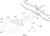
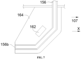
- FIG. 5 shows an example of the embodiment of the evacuation system 150 and the Figs. 6 And 7 show sections of said evacuation system 150.
- the evacuation system 150 is arranged here at the level of the wing 104 in the vicinity of the consumer device 106, here the propulsion system 106 which is supplied by the transport pipe 112a.
- the evacuation system 150 comprises a first pipe 152 which has a proximal end 152a, a distal end 152b and an elbow 154 between the proximal end 152a and the distal end 152b, where the elbow 154 constitutes a low point for the first pipe 152, that is to say that between the proximal end 152a and the elbow 154, on the one hand, and between the distal end 152b and the elbow 154, on the other hand, the first pipe 152 has downward slopes.
- the first pipe 152 is fluidically connected to the second end 632 of the gutter 202, here of the lower gutter 523 of said gutter 202, by its proximal end 152a and opens to the outside of the aircraft 100 at an outer wall of the aircraft 100, here of the wing 104, by its distal end 152b.
- An outer wall of the aircraft 100 is in direct contact with the outside air surrounding the aircraft 100.
- the distal end 152b of the first pipe 152 opens onto the upper surface of the wing 104 of the aircraft 100.
- a depression is created at the upper surface of the wing 104, and as the first pipe 152 is fluidically connected by its distal end 152b, to the upper surface of the wing 104, there is a suction of the outside air surrounding the aircraft 100 into the first duct 152, which maximizes the air flow in said first duct 152.
- the first pipe 152 ensures the evacuation of air and dihydrogen in the event of a leak from the transport pipe 112a into the gutter 202 by ensuring evacuation over the entire length of said gutter 202.
- the first part of the first pipe 152, between its proximal end 152a and the elbow 154, also ensures the evacuation of water from the gutter 202.
- the elbow 154 corresponds to a low point of the first pipe 152, it is at the level of the elbow 154 that the water separates, by gravity, from the air and dihydrogen.
- the evacuation system 150 comprises a second pipe 156 which has a proximal end 156a and a distal end 156b, where the second pipe 156 is fluidically connected to the elbow 154 by its proximal end 156a and opens outside the aircraft 100 at an exterior wall of the aircraft 100, here of the consumer device 106, by its distal end 156b.
- the second pipe 156 has a downward slope to ensure the flow of water or any other liquid towards the outside and thus ensuring drainage over the entire length of said gutter 202.
- the evacuation system 150 comprises a cover 160 which extends outside the aircraft 100 around the distal end 152b, having a closed face facing the front of the aircraft 100 and an open face facing the rear of the aircraft 100.
- the gases present in the first pipe 152 are then sucked in by the outside air due to the speed of movement of the aircraft 100.
- the cover 160 is fixed to the outer wall of the aircraft 100.
- the evacuation system 150 comprises a heating element 162, for example an electrically powered electrical resistor, which is arranged near said second pipe 156.
- heating element 162 is arranged in a fin 164 in which the second pipe 156 is enclosed.
- the distal end 156b of the second pipe 156 is oriented towards the rear of the aircraft 100.
Landscapes
- Engineering & Computer Science (AREA)
- Aviation & Aerospace Engineering (AREA)
- Traffic Control Systems (AREA)
- Filling Or Discharging Of Gas Storage Vessels (AREA)
- Jet Pumps And Other Pumps (AREA)
- Rigid Pipes And Flexible Pipes (AREA)
Claims (5)
- Luftfahrzeug (100) umfassend:- mindestens eine Transportleitung (112a-b), in der Dihydrogen fließt, zwischen einem stromaufwärtigen Behälter (110) und einer stromabwärtigen Verbrauchervorrichtung (106),- für jede Transportleitung (112a-b) einen Einbettungskanal (200) mit einer Rinne (202), in der die Transportleitung (112a-b) befestigt ist und die ein erstes Ende (630), durch das die von stromaufwärts kommende Transportleitung (112a-b) in die Rinne (202) eintritt, und ein zweites Ende (632), durch das die nach stromabwärts verlaufende Transportleitung (112a-b) aus der Rinne (202) austritt, aufweist, und- für jedes zweite Ende (632) ein Ableitungssystem (150), das fluidisch zwischen das zweite Ende (632) der Rinne (202) und das Äußere des Luftfahrzeugs (100) geschaltet ist,wobei das Ableitungssystem (150) Folgendes umfasst:- eine erste Rohrleitung (152) mit einem proximalen Ende (152a), einem distalen Ende (152b) und einer Krümmung (154) zwischen dem proximalen Ende (152a) und dem distalen Ende (152b), wobei die Krümmung (154) einen Tiefpunkt für die erste Rohrleitung (152) bildet und die erste Rohrleitung (152) über das proximale Ende (152a) fluidisch mit dem zweiten Ende (632) der Rinne (202) verbunden ist und über das distale Ende (152b) an einer Außenwand des Luftfahrzeugs (100) nach außen mündet, und- eine zweite Rohrleitung (156) mit einem proximalen Ende (156a) und einem distalen Ende (156b), wobei die zweite Rohrleitung (156) über das proximale Ende (156a) fluidisch mit der Krümmung (154) verbunden ist und über das distale Ende (156b) an einer Außenwand des Luftfahrzeugs (100) nach außerhalb des Luftfahrzeugs (100) mündet, und wobei die zweite Rohrleitung (156) zwischen dem proximalen Ende (156a) der zweiten Rohrleitung (156) und dem distalen Ende (156b) der zweiten Rohrleitung (156) ein absteigendes Gefälle aufweist.
- Luftfahrzeug (100) nach Anspruch 1, dadurch gekennzeichnet, dass es einen Flügel (104) aufweist und dass das distale Ende (152b) der ersten Rohrleitung (152) auf der Oberseite des Flügels (104) mündet.
- Luftfahrzeug (100) nach einem der Ansprüche 1 oder 2, dadurch gekennzeichnet, dass das Ableitungssystem (150) eine Haube (160) umfasst, die sich außerhalb des Luftfahrzeugs (100) um das distale Ende (152b) herum erstreckt und dabei eine zur Vorderseite des Luftfahrzeugs (100) ausgerichtete geschlossene Seite und eine zur Rückseite des Luftfahrzeugs (100) ausgerichtete offene Seite aufweist.
- Luftfahrzeug (100) nach einem der Ansprüche 1 bis 3, dadurch gekennzeichnet, dass das Ableitungssystem (150) ein Heizelement (162) aufweist, das in der Nähe der zweiten Rohrleitung (156) angeordnet ist.
- Luftfahrzeug (100) nach einem der Ansprüche 1 oder 4, dadurch gekennzeichnet, dass das distale Ende (156b) der zweiten Rohrleitung (156) zur Rückseite des Luftfahrzeugs (100) hin ausgerichtet ist.
Applications Claiming Priority (1)
| Application Number | Priority Date | Filing Date | Title |
|---|---|---|---|
| FR2303001 | 2023-03-29 |
Publications (2)
| Publication Number | Publication Date |
|---|---|
| EP4438487A1 EP4438487A1 (de) | 2024-10-02 |
| EP4438487B1 true EP4438487B1 (de) | 2025-05-14 |
Family
ID=86852120
Family Applications (1)
| Application Number | Title | Priority Date | Filing Date |
|---|---|---|---|
| EP24159662.6A Active EP4438487B1 (de) | 2023-03-29 | 2024-02-26 | Flugzeug mit einer diwasserstofftransportleitung, einem eingrabenkanal dieser transportleitung und einem system zur luft- und wasserabführung in diesem eingrabenkanal |
Country Status (3)
| Country | Link |
|---|---|
| US (1) | US12404035B2 (de) |
| EP (1) | EP4438487B1 (de) |
| CN (1) | CN118723097A (de) |
Family Cites Families (7)
| Publication number | Priority date | Publication date | Assignee | Title |
|---|---|---|---|---|
| JP6419437B2 (ja) * | 2014-02-28 | 2018-11-07 | 三菱航空機株式会社 | 航空機のエンジンパイロンおよび航空機 |
| JP2017165242A (ja) * | 2016-03-16 | 2017-09-21 | 三菱航空機株式会社 | 航空機の燃料配管および航空機 |
| FR3100799B1 (fr) * | 2019-09-16 | 2021-09-24 | Airbus Operations Sas | Aeronef comportant des etais de soutien pour des ailes dans lesquelles sont agences des conduites d’hydrogene ou des conducteurs electriques |
| FR3120603A1 (fr) | 2021-03-11 | 2022-09-16 | Airbus Operations (S.A.S.) | Mât d’aéronef comprenant une structure primaire tubulaire intégrant au moins une canalisation à double peau et aéronef comportant au moins un tel mât |
| FR3127203A1 (fr) | 2021-09-22 | 2023-03-24 | Airbus | Aéronef comportant une canalisation de transport de dihydrogène et un canal d’enfouissement de ladite canalisation de transport |
| EP4249380B1 (de) * | 2022-03-21 | 2025-07-30 | Zero Emissions Aerospace Limited | Kraftstoffleitungs-sicherheitsschutzsystem |
| EP4265897B1 (de) * | 2022-04-22 | 2025-09-24 | Eaton Intelligent Power Limited | Wasserstoffbrennstoffsystem für flugzeuge |
-
2024
- 2024-02-26 EP EP24159662.6A patent/EP4438487B1/de active Active
- 2024-03-25 CN CN202410343756.XA patent/CN118723097A/zh active Pending
- 2024-03-27 US US18/618,261 patent/US12404035B2/en active Active
Also Published As
| Publication number | Publication date |
|---|---|
| EP4438487A1 (de) | 2024-10-02 |
| US12404035B2 (en) | 2025-09-02 |
| US20240327024A1 (en) | 2024-10-03 |
| CN118723097A (zh) | 2024-10-01 |
Similar Documents
| Publication | Publication Date | Title |
|---|---|---|
| EP4155213B1 (de) | Flugzeug mit einer diwasserstofftransportleitung und einem eingrabenkanal der besagten transportleitung | |
| CA2581540C (fr) | Systeme de degivrage d'un cone d'entree de turbomoteur pour aeronef | |
| EP4166771B1 (de) | Antriebseinheit für ein flugzeug | |
| EP4124738B1 (de) | Antriebsanordnung für luftfahrzeug | |
| EP2250357A1 (de) | Luftansaugstruktur für eine flugzeugtriebwerksgondel | |
| CA2652363A1 (fr) | Nacelle de turboreacteur equipee de moyens de reduction du bruit engendre par ce turboreacteur | |
| WO2014202881A1 (fr) | Ventilation d'une nacelle de turbomachine | |
| EP3701171A1 (de) | Antriebseinheit für ein flugzeug | |
| EP3945033A1 (de) | Flugzeugantriebseinheit | |
| EP4438487B1 (de) | Flugzeug mit einer diwasserstofftransportleitung, einem eingrabenkanal dieser transportleitung und einem system zur luft- und wasserabführung in diesem eingrabenkanal | |
| WO2017013362A1 (fr) | Ensemble propulsif pour aeronef comportant un inverseur de poussee | |
| EP4286019B1 (de) | Flugzeug mit einer diwasserstofftransportleitung, einem eingrabenkanal dieser transportleitung und einem belüftungssystem des eingrabenkanals | |
| FR2951436A1 (fr) | Mat d'accrochage de turbomoteur d'aeronef a canalisations d'air chaud concentriques | |
| EP4455022B1 (de) | Flugzeug mit einer rohrleitung zum transport von diwasserstoff und einem system zur extraktion von diesem wasserstoff nach aussen | |
| EP4438488B1 (de) | Flugzeugantriebsanordnung mit gondel mit t-förmigem rahmen | |
| FR2741321A1 (fr) | Agencement de dispositifs d'echappement pour le degagement de vapeurs cryogenes inflammables | |
| EP4293212B1 (de) | Gehäusesystem mit wärmetauscher zur erwärmung von dihydrogen | |
| FR3156430A1 (fr) | Ensemble pour la mise à l’air libre d’un volume de dihydrogène gazeux issu d’un dispositif contenant du dihydrogène | |
| EP4435316B1 (de) | Modul für ein diwasserstoff-versorgungssystem für einen flugzeugmotor | |
| EP4538514A1 (de) | Antriebseinheit für ein flugzeug | |
| FR3153077A1 (fr) | Ensemble propulsif pour aéronef | |
| EP4538513A1 (de) | Antriebseinheit für ein flugzeug | |
| EP4452757A1 (de) | Integration eines feuerlöschers in eine feuer-zone einer turbomaschine | |
| EP4538515A1 (de) | Antriebseinheit für ein flugzeug mit einem wärmeaustauschsystem in der abgasdüse | |
| EP4495010A1 (de) | Modul für ein flugzeug mit einem system zur verarbeitung von diwasserstoff |
Legal Events
| Date | Code | Title | Description |
|---|---|---|---|
| PUAI | Public reference made under article 153(3) epc to a published international application that has entered the european phase |
Free format text: ORIGINAL CODE: 0009012 |
|
| STAA | Information on the status of an ep patent application or granted ep patent |
Free format text: STATUS: REQUEST FOR EXAMINATION WAS MADE |
|
| 17P | Request for examination filed |
Effective date: 20240226 |
|
| AK | Designated contracting states |
Kind code of ref document: A1 Designated state(s): AL AT BE BG CH CY CZ DE DK EE ES FI FR GB GR HR HU IE IS IT LI LT LU LV MC ME MK MT NL NO PL PT RO RS SE SI SK SM TR |
|
| GRAP | Despatch of communication of intention to grant a patent |
Free format text: ORIGINAL CODE: EPIDOSNIGR1 |
|
| STAA | Information on the status of an ep patent application or granted ep patent |
Free format text: STATUS: GRANT OF PATENT IS INTENDED |
|
| RIC1 | Information provided on ipc code assigned before grant |
Ipc: B64D 27/12 20060101ALN20241030BHEP Ipc: B64D 37/20 20060101ALI20241030BHEP Ipc: B64D 37/32 20060101ALI20241030BHEP Ipc: B64D 37/30 20060101ALI20241030BHEP Ipc: B64D 29/02 20060101AFI20241030BHEP |
|
| INTG | Intention to grant announced |
Effective date: 20241114 |
|
| GRAS | Grant fee paid |
Free format text: ORIGINAL CODE: EPIDOSNIGR3 |
|
| GRAA | (expected) grant |
Free format text: ORIGINAL CODE: 0009210 |
|
| STAA | Information on the status of an ep patent application or granted ep patent |
Free format text: STATUS: THE PATENT HAS BEEN GRANTED |
|
| AK | Designated contracting states |
Kind code of ref document: B1 Designated state(s): AL AT BE BG CH CY CZ DE DK EE ES FI FR GB GR HR HU IE IS IT LI LT LU LV MC ME MK MT NL NO PL PT RO RS SE SI SK SM TR |
|
| REG | Reference to a national code |
Ref country code: GB Ref legal event code: FG4D Free format text: NOT ENGLISH |
|
| REG | Reference to a national code |
Ref country code: CH Ref legal event code: EP |
|
| REG | Reference to a national code |
Ref country code: IE Ref legal event code: FG4D Free format text: LANGUAGE OF EP DOCUMENT: FRENCH |
|
| REG | Reference to a national code |
Ref country code: DE Ref legal event code: R096 Ref document number: 602024000122 Country of ref document: DE |
|
| REG | Reference to a national code |
Ref country code: NL Ref legal event code: MP Effective date: 20250514 |
|
| PG25 | Lapsed in a contracting state [announced via postgrant information from national office to epo] |
Ref country code: PT Free format text: LAPSE BECAUSE OF FAILURE TO SUBMIT A TRANSLATION OF THE DESCRIPTION OR TO PAY THE FEE WITHIN THE PRESCRIBED TIME-LIMIT Effective date: 20250915 Ref country code: ES Free format text: LAPSE BECAUSE OF FAILURE TO SUBMIT A TRANSLATION OF THE DESCRIPTION OR TO PAY THE FEE WITHIN THE PRESCRIBED TIME-LIMIT Effective date: 20250514 Ref country code: FI Free format text: LAPSE BECAUSE OF FAILURE TO SUBMIT A TRANSLATION OF THE DESCRIPTION OR TO PAY THE FEE WITHIN THE PRESCRIBED TIME-LIMIT Effective date: 20250514 |
|
| REG | Reference to a national code |
Ref country code: LT Ref legal event code: MG9D |
|
| PG25 | Lapsed in a contracting state [announced via postgrant information from national office to epo] |
Ref country code: NO Free format text: LAPSE BECAUSE OF FAILURE TO SUBMIT A TRANSLATION OF THE DESCRIPTION OR TO PAY THE FEE WITHIN THE PRESCRIBED TIME-LIMIT Effective date: 20250814 Ref country code: GR Free format text: LAPSE BECAUSE OF FAILURE TO SUBMIT A TRANSLATION OF THE DESCRIPTION OR TO PAY THE FEE WITHIN THE PRESCRIBED TIME-LIMIT Effective date: 20250815 |
|
| PG25 | Lapsed in a contracting state [announced via postgrant information from national office to epo] |
Ref country code: PL Free format text: LAPSE BECAUSE OF FAILURE TO SUBMIT A TRANSLATION OF THE DESCRIPTION OR TO PAY THE FEE WITHIN THE PRESCRIBED TIME-LIMIT Effective date: 20250514 Ref country code: NL Free format text: LAPSE BECAUSE OF FAILURE TO SUBMIT A TRANSLATION OF THE DESCRIPTION OR TO PAY THE FEE WITHIN THE PRESCRIBED TIME-LIMIT Effective date: 20250514 |
|
| REG | Reference to a national code |
Ref country code: AT Ref legal event code: MK05 Ref document number: 1794618 Country of ref document: AT Kind code of ref document: T Effective date: 20250514 |
|
| PG25 | Lapsed in a contracting state [announced via postgrant information from national office to epo] |
Ref country code: BG Free format text: LAPSE BECAUSE OF FAILURE TO SUBMIT A TRANSLATION OF THE DESCRIPTION OR TO PAY THE FEE WITHIN THE PRESCRIBED TIME-LIMIT Effective date: 20250514 |
|
| PG25 | Lapsed in a contracting state [announced via postgrant information from national office to epo] |
Ref country code: HR Free format text: LAPSE BECAUSE OF FAILURE TO SUBMIT A TRANSLATION OF THE DESCRIPTION OR TO PAY THE FEE WITHIN THE PRESCRIBED TIME-LIMIT Effective date: 20250514 |
|
| PG25 | Lapsed in a contracting state [announced via postgrant information from national office to epo] |
Ref country code: AT Free format text: LAPSE BECAUSE OF FAILURE TO SUBMIT A TRANSLATION OF THE DESCRIPTION OR TO PAY THE FEE WITHIN THE PRESCRIBED TIME-LIMIT Effective date: 20250514 |
|
| PG25 | Lapsed in a contracting state [announced via postgrant information from national office to epo] |
Ref country code: RS Free format text: LAPSE BECAUSE OF FAILURE TO SUBMIT A TRANSLATION OF THE DESCRIPTION OR TO PAY THE FEE WITHIN THE PRESCRIBED TIME-LIMIT Effective date: 20250814 |
|
| PG25 | Lapsed in a contracting state [announced via postgrant information from national office to epo] |
Ref country code: IS Free format text: LAPSE BECAUSE OF FAILURE TO SUBMIT A TRANSLATION OF THE DESCRIPTION OR TO PAY THE FEE WITHIN THE PRESCRIBED TIME-LIMIT Effective date: 20250914 |
|
| PG25 | Lapsed in a contracting state [announced via postgrant information from national office to epo] |
Ref country code: LV Free format text: LAPSE BECAUSE OF FAILURE TO SUBMIT A TRANSLATION OF THE DESCRIPTION OR TO PAY THE FEE WITHIN THE PRESCRIBED TIME-LIMIT Effective date: 20250514 |
|
| PG25 | Lapsed in a contracting state [announced via postgrant information from national office to epo] |
Ref country code: SM Free format text: LAPSE BECAUSE OF FAILURE TO SUBMIT A TRANSLATION OF THE DESCRIPTION OR TO PAY THE FEE WITHIN THE PRESCRIBED TIME-LIMIT Effective date: 20250514 Ref country code: DK Free format text: LAPSE BECAUSE OF FAILURE TO SUBMIT A TRANSLATION OF THE DESCRIPTION OR TO PAY THE FEE WITHIN THE PRESCRIBED TIME-LIMIT Effective date: 20250514 |
|
| PG25 | Lapsed in a contracting state [announced via postgrant information from national office to epo] |
Ref country code: CZ Free format text: LAPSE BECAUSE OF FAILURE TO SUBMIT A TRANSLATION OF THE DESCRIPTION OR TO PAY THE FEE WITHIN THE PRESCRIBED TIME-LIMIT Effective date: 20250514 |
|
| PG25 | Lapsed in a contracting state [announced via postgrant information from national office to epo] |
Ref country code: EE Free format text: LAPSE BECAUSE OF FAILURE TO SUBMIT A TRANSLATION OF THE DESCRIPTION OR TO PAY THE FEE WITHIN THE PRESCRIBED TIME-LIMIT Effective date: 20250514 |
|
| PG25 | Lapsed in a contracting state [announced via postgrant information from national office to epo] |
Ref country code: SK Free format text: LAPSE BECAUSE OF FAILURE TO SUBMIT A TRANSLATION OF THE DESCRIPTION OR TO PAY THE FEE WITHIN THE PRESCRIBED TIME-LIMIT Effective date: 20250514 |
|
| PG25 | Lapsed in a contracting state [announced via postgrant information from national office to epo] |
Ref country code: IT Free format text: LAPSE BECAUSE OF FAILURE TO SUBMIT A TRANSLATION OF THE DESCRIPTION OR TO PAY THE FEE WITHIN THE PRESCRIBED TIME-LIMIT Effective date: 20250514 |
|
| PLBE | No opposition filed within time limit |
Free format text: ORIGINAL CODE: 0009261 |
|
| STAA | Information on the status of an ep patent application or granted ep patent |
Free format text: STATUS: NO OPPOSITION FILED WITHIN TIME LIMIT |
|
| REG | Reference to a national code |
Ref country code: CH Ref legal event code: L10 Free format text: ST27 STATUS EVENT CODE: U-0-0-L10-L00 (AS PROVIDED BY THE NATIONAL OFFICE) Effective date: 20260325 |